
Image not available
Illustrative purposes only

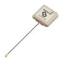
ADFGP.25A.07.0060A
Antenna, Patch, 1.559 GHz to 1.61 GHz, -4 dBi, Right Hand Circular, UFL Connector
⚠️ Reference pricing provided. In case of supply shortages, we will connect you with our trusted procurement partners to ensure your project's continuity.
- Manufacturer: TAOGLAS
- Product type:
- Gain: -4dBi
- SVHC: To Be Advised
- VSWR: 2
- Input Power: -
- Antenna Type: Patch
- Frequency Max: 1.61GHz
- Frequency Min: 1.559GHz
- Product Range: ADFGP.25A Series
- Input Impedance: 50ohm
- Antenna Mounting: UFL Connector
- Antenna Polarisation: Right Hand Circular
| Delivery and price | |
|---|---|
| Units per pack | 100 |
| Price | 17.0 € |
| Current stock | 10+ |
| Lead time | 30 days |
Datasheet

aD

Y) © + ©

|1.|Introduction|3|
|---|---|---|
|2.|Specifications|5|
|3.|Antenna Characteristics|9|
|4.|Radiation Patterns|12|
|5.|LNA Characteristics|16|
|6.|Mechanical Drawing|18|
|7.|Packaging|19|
||Changelog|20|


Taoglas makes no warranties based on the accuracy or completeness of the contents of this document and reserves the right to make changes to specifications and product descriptions at any time without notice. Taoglas reserves all rights to this document and the information contained herein. Reproduction, use or disclosure to third parties without express permission is strictly prohibited.

www.taoglas.com

SPE-19-8-111-B

2

## 1. Introduction

The ADFGP.25A is an embedded patch antenna covering 1559MHz to 1610MHz. It has a dual feed, active patch design which makes it ideal for next-generation GNSS devices that require excellent positional accuracy in a small factor. The active patch antenna, by means of a double resonance design, has a wide-band operation over GNSS systems including GPS (L1), GLONASS (G1), Galileo (E1) and BeiDou(B1). The 25 mm patch uses a dual-feed configuration that combines both feeds with a 90° hybrid coupler to obtain an optimal axial ratio.

The ADFGP.25A includes an LNA and front-end SAW filter to reduce out of band noise, such as from nearby cellular transceivers. It offers better protection from nearby radiated power surges and greatly reduces the probability of damaging your GNSS receiver from nearby transmissions. The ADFGP.25A is manufactured and tested in a TS16949 first tier automotive approved facility.

The antenna is supplied with Ø1.13 cable and an IPEX MHFI (U.FL compatible) connector. The patch, the PCB (ground plane), the LNA, and front-end SAW components are all integrated into a form factor of just 25.1 x 25.1 x 7.5 mm. It connects via a 60mm Ø1.13 coaxial cable and IPEX MHFI connector.

## Features:

- Compact Dual Feed Patch Antenna

- Excellent signal to noise ratio (C/N0)

- Good 2DRMS and fast TTFF

- Axial ratio < 5dB typ. across all bands

www.taoglas.com

SPE-19-8-111-B

3

## Benefits:

- Excellent positional accuracy

- Great for use in difficult environments

- Excellent out-of-band signal rejection

- Ideal antenna solution for RTK systems.

## Typical applications include:

- High accuracy positioning and navigation systems

- UAVs, Robotics & Autonomous Vehicles

- Micro-Mobility Solutions

- Mapping & GIS

- Transportation & Telematics

- Precision Agriculture

- Public Safety, Search & Rescue

- RTK Systems

Custom antenna modifications are subject to possible NRE and minimum order quantity. For further information or support to test and integrate Taoglas Sure technology please contact your regional Taoglas customer support team.

www.taoglas.com

SPE-19-8-111-B

4

## **2.** Specifications

**==> picture [39 x 42] intentionally omitted <==**

|**GNSS Frequency Bands Covered**|**GNSS Frequency Bands Covered**|**GNSS Frequency Bands Covered**|**GNSS Frequency Bands Covered**|**GNSS Frequency Bands Covered**|**GNSS Frequency Bands Covered**|||
|---|---|---|---|---|---|---|---|
|**GPS/QZSS**|L1<br>1575.42MHz|L2<br>1227.6MHz|L5<br>1176.45MHz|L6<br>1278.75MHz||||
||`▓`|□|□|□||||
|**GLONASS**|L5R<br>1176.45MHz|L3PT<br>1201.5MHz|L2PT<br>1246MHz|L1CR<br>1575.42MHz|L1PT<br>1602MHz|||
||□|□|□|`▓`|`▓`|||
|**Galileo**|E5a<br>1176.45MHz|E5b<br>1201.5MHz|E4<br>1215MHz|E3<br>1256MHz|E6<br>1278.75MHz|E2<br>1561MHz|L1<br>1575.42MHz|
||□|□|□|□|□|`▓`|`▓`|
|**BeiDou**|B1<br>1561MHz|B2<br>1207.14MHz|B3<br>1268.52MHz|||||
||`▓`|□|□|||||
|**Compass**|E5B(B2)/ E6(B3)<br>1268.56MHz|E2(B1)<br>1561MHz||||||
||□|`▓`||||||
|**SBAS**|Omnistar<br>1542.5MHz|WAAS/EGN OS<br>1575.42MHz||||||
||□|`▓`||||||


|**GNSS Electrical**|**GNSS Electrical**|**GNSS Electrical**|**GNSS Electrical**|
|---|---|---|---|
|**Frequency (MHz)**|**1561**|**1575.42**|**1602**|
|VSWR (max.)|2.0:1|2.0:1|2.0:1|
|Efficiency (%)|40.5|55.1|38.9|
|Peak Gain at Zenith (dBi)|1.6|3.0|1.7|
|Average Gain|-3|-2.5|-4|
|Polarization|R.H.C.P.|||
|Impedance|50Ω|||


Note. The patch antenna test with hybrid coupler XC1400P-03S

www.taoglas.com

SPE-19-8-111-B

5

|**LNA and Filter Electrical Properties**|**LNA and Filter Electrical Properties**|**LNA and Filter Electrical Properties**|**LNA and Filter Electrical Properties**|
|---|---|---|---|
|**Frequency (MHz)**|**1561**|**1575.42**|**1602**|
|VSWR (max.)|2.0:1|2.0:1|2.0:1|
|Gain@1.8V (Typ.)|31.3 dB|30.2 dB|29.8 dB|
|Gain@3.0V (Typ.)|31.1 dB|32.5 dB|32.0 dB|
|Gain@5.5V (Typ.)|33.5 dB|33.0 dB|33.1 dB|
|Noise@1.8V (Typ.)|3.1 dB|2.7 dB|3.1 dB|
|Noise@3.0V (Typ.)|3.3 dB|2.9 dB|3.3 dB|
|Noise@5.5V (Typ.)|3.3 dB|2.9 dB|3.2 dB|
|Power consumption@1.8V (Typ.)|5.0mA|||
|Power consumption@3.0V (Typ.)|5.1mA|||
|Power consumption@5.5V (Typ.)|5.2mA|||
|**Total Specification (Through Antenna, SAW Filter and LNA)**||||
|**Frequency (MHz)**|**1561**|**1575.42**|**1602**|
|Gain@3V (dB)|32.8dB|35.5dB|33.7dB|
|Output Impedance|50 Ω|||
|Phase Centre Offset|0.8 mm|||
||**Field Test Result**|||
|RTK Result|1.4 cm|||
|CN Value (Typ)|40 dB-Hz|||
|Accuracy|76 cm|||


|**Total Specification (Through Antenna, SAW Filter and LNA)**|**Total Specification (Through Antenna, SAW Filter and LNA)**|**Total Specification (Through Antenna, SAW Filter and LNA)**|**Total Specification (Through Antenna, SAW Filter and LNA)**||
|---|---|---|---|---|
|**Frequency (MHz)**|**1561**|**1575.42**||**1602**|
|Gain@3V (dB)|32.8dB|35.5dB||33.7dB|
|Output Impedance||50 Ω|||
|Phase Centre Offset||0.8 mm|||
||**Field Test Result**||||
|RTK Result||1.4 cm|||
|CN Value (Typ)||40 dB-Hz|||
|Accuracy||76 cm|||


www.taoglas.com 6

SPE-19-8-111-B

|**Field Test Result with 70*70mm ground plane**|**Field Test Result with 70*70mm ground plane**|**Field Test Result with 70*70mm ground plane**|**Field Test Result with 70*70mm ground plane**|**Field Test Result with 70*70mm ground plane**|
|---|---|---|---|---|
|**Frequency**|**GPS L1**|**Galileo E1**|**GLONASS G1**|**BeiDou B1I**|
||**1563-1587**|**1559-1591**|**1598-1605**|**1559-1563**|
|Carrier-to-Noise<br>Values(dB-Hz)|44.33|43|39|43.25|
|2*DRMS Positioning<br>Accuracy (cm)<br>**without** **RTK**|76|76|76|76|
|2*DRMS Positioning<br>Accuracy (cm)**with**<br>**RTK**|1.4|1.4|1.4|1.4|
|TTFF(s)|57|57|57|57|
|Group Delay @ Zenith<br>Variation Across<br>Single<br>Constellation(ns)|10|10|10|10|
|Phase Centre Offset<br>PCO (cm)|0.2|0.2|0.2|0.2|
|Phase Centre<br>Variation<br>PCV (mm)|0.8|0.8|0.8|0.8|
|Axial Ratio (dB)|3.4|3.4|3.4|3.4|


*All outdoor measurements performed on the roof top of the Taoglas R&D Labs facility in Dublin Ireland.

** Recommended Minimum C/No for Standard Precision Acquisition/ Tracking (dB-Hz): 26-30/ 12-15.

***Data Measured Free Space.

****Group Delay, PCO, PCV and Axial Ratio values includes Active Circuitry. *****Ublox C099-F9P application board is used for Field test Measurements.

www.taoglas.com 7

SPE-19-8-111-B

||**Mechanical**|
|---|---|
|Ceramic Dimension|25 x 25 x 4.0mm|
|Total Dimension<br>(Including Shielding Case)|28x28 mm|
|Connector|IPEX MHFI (U.FL)|
|Cable|Coaxial Cable ø1.13, length 60mm|
|Weight|13.5g|
||**Environmental**<br><br><br>|
|Operation Temperature|~~E~~<br>~~i~~<br>~~l~~<br>-40°C to 85°C|
|Storage Temperature|-40°C to 85°C|
|Humidity|Non-condensing 65°C 95% RH|
|RoHS Compliant|Yes|
|REACH Compliant|Yes|


www.taoglas.com 8

SPE-19-8-111-B

## **3.** Antenna Characteristics

## **3.1** Return Loss |[4]

**==> picture [420 x 237] intentionally omitted <==**

**----- Start of picture text -----**<br>
0<br>-5<br>-10<br>-15<br>-20<br>1400 1450 1500 1550 1600 1650 1700<br>Frequnecy (MHz)<br>Return Loss (dB)<br>**----- End of picture text -----**<br>


## **3.2** Efficiency |[4]

**==> picture [431 x 246] intentionally omitted <==**

**----- Start of picture text -----**<br>
100<br>90<br>80<br>70<br>60<br>50<br>40<br>30<br>20<br>10<br>0<br>1400 1450 1500 1550 1600 1650 1700<br>Frequency (MHz)<br>Efficiency (%)<br>**----- End of picture text -----**<br>


www.taoglas.com

SPE-19-8-111-B

9

## **3.3** Average Gain |[4]

**==> picture [430 x 241] intentionally omitted <==**

**----- Start of picture text -----**<br>
5<br>0<br>-5<br>-10<br>1400 1450 1500 1550 1600 1650 1700<br>Frequency (MHz)<br>Average Gain (dB)<br>**----- End of picture text -----**<br>


## **3.4** Peak Gain |[4]

**==> picture [426 x 253] intentionally omitted <==**

**----- Start of picture text -----**<br>
10<br>5<br>0<br>-5<br>1400 1450 1500 1550 1600 1650 1700<br>Frequency (MHz)<br>Peak Gain (dBi)<br>**----- End of picture text -----**<br>


www.taoglas.com

SPE-19-8-111-B

10

## **3.5** Axial Ratio

**==> picture [479 x 534] intentionally omitted <==**

**----- Start of picture text -----**<br>
X-Z<br>10<br>9<br>8<br>7<br>6<br>5<br>4<br>3<br>2<br>1561MHz<br>1 1602MHz<br>1575.42MHz<br>0<br>-180 -150 -120 -90 -60 -30 0 30 60 90 120 150 180 (degree)<br>Y-Z<br>10<br>9<br>8<br>7<br>6<br>5<br>4<br>3<br>2<br>1561MHz<br>1 1602MHz<br>1575.42MHz<br>A I<br>0<br>-180 -150 -120 -90 -60 -30 0 30 60 90 120 150 180 (degree)<br>(dB)<br>(dB)<br>**----- End of picture text -----**<br>


www.taoglas.com

SPE-19-8-111-B

11

## **4.** Radiation Patterns

**4.**

**==> picture [105 x 12] intentionally omitted <==**

**----- Start of picture text -----**<br>
4.1 Test Setup<br>**----- End of picture text -----**<br>


**==> picture [65 x 101] intentionally omitted <==**

**----- Start of picture text -----**<br>
Y<br>X<br>Z<br>**----- End of picture text -----**<br>


On 70*70mm Ground Plane

www.taoglas.com

SPE-19-8-111-B

12

## **4.2** 1561MHz 3D and 2D Radiation Patterns ff

XY Plane XZ Plane YZ Plane ~~ee~~ eee

**==> picture [482 x 141] intentionally omitted <==**

**----- Start of picture text -----**<br>
X  Z  Z<br>0 1561MHz 0 1561MHz 0 1561MHz<br>10<br>10 330 30 10<br>330 30 0 330 30<br>0 0<br>-10<br>-10 300 60 -10<br>300 60 -20 300 60<br>-20 -20<br>-30<br>-30 -30<br>270 -40 90 Y  270 -40 90 X  270 -40 90 Y<br>240 120<br>240 120 240 120<br>210 150<br>210 150 210 150<br>180 (dBi) 180 (dBi) 180 (dBi)<br>**----- End of picture text -----**<br>


www.taoglas.com 13

SPE-19-8-111-B

## **4.3** 1575.42MHz 3D and 2D Radiation Patterns | 4

XY Plane XZ Plane YZ Plane ~~ee~~ eee

**==> picture [488 x 142] intentionally omitted <==**

**----- Start of picture text -----**<br>
X  Z  Z<br>0 1575.42MHz 0 1575.42MHz 0 1575.42MHz<br>10<br>10 330 30 10<br>330 30 0 330 30<br>0 0<br>-10<br>-10 300 60 -10<br>300 60 -20 300 60<br>-20 -20<br>-30<br>-30 -30<br>270 -40 90 Y  270 -40 90 X  270 -40 90 Y<br>240 120<br>240 120 240 120<br>210 150<br>210 150 210 150<br>180 (dBi) 180 (dBi) 180 (dBi)<br>**----- End of picture text -----**<br>


www.taoglas.com 14

SPE-19-8-111-B

## **4.4** 1602MHz 3D and 2D Radiation Patterns ff

**==> picture [495 x 173] intentionally omitted <==**

**----- Start of picture text -----**<br>
XY Plane   XZ Plane   YZ Plane<br>rr ee eee<br>X  Z  Z<br>0 1602MHz 0 1602MHz 0 1602MHz<br>10<br>10 330 30 10<br>330 30 0 330 30<br>0 0<br>-10<br>-10 300 60 -10<br>300 60 -20 300 60<br>-20 -20<br>-30<br>-30 -30<br>270 -40 90 Y  270 -40 90 X  270 -40 90 Y<br>240 120<br>240 120 240 120<br>210 150<br>210 150 210 150<br>180 (dBi) 180 (dBi) 180 (dBi)<br>**----- End of picture text -----**<br>


www.taoglas.com 15

SPE-19-8-111-B

## **5.** LNA Characteristics

**==> picture [223 x 13] intentionally omitted <==**

**----- Start of picture text -----**<br>
5.1 Block Diagram (Active Antenna)<br>**----- End of picture text -----**<br>


## **5.2** LNA Gain & Noise Figure

www.taoglas.com

SPE-19-8-111-B

16

## **5.3** S12 Wide Band Plot

www.taoglas.com

SPE-19-8-111-B

17

## **6.** Mechanical Drawing (Units: mm)

www.taoglas.com 18

SPE-19-8-111-B

## **7.** Packaging

30pcs ADFGP.25A.07.0060A per Tray Weight: 615g

150pcs ADFGP.25A.07.0060A per PE Bag Dimensions: 420*560 mm Weight: 3.075Kg

450pcs ADFGP.25A per carton Dimensions - 390*320*290mm Weight: 9.4Kg

**==> picture [189 x 66] intentionally omitted <==**

**----- Start of picture text -----**<br>
290mm<br>320mm<br>390mm<br>**----- End of picture text -----**<br>


www.taoglas.com

SPE-19-8-111-B

19

Changelog for the datasheet **SPE-19-8-111 – ADFGP.25A.07.0060A Revision: B (Current Version)** Date: 2020-02-28 Changes: RTK Table and introduction Updated Changes Made by: Yu Kai Yeung

## **Previous Revisions**

**Revision: A** Date: 2019-08-19 Changes: Initial Release Changes Made by: Jack Conroy

www.taoglas.com

SPE-19-8-111-B

20

www.taoglas.com

©Taoglas

www.taoglas.com 21

SPE-19-8-111-B
Updated at June 9, 2026
About Novapart
Novapart is a B2B electronic component broker specialising in stock shortages and cost reduction. We source hard-to-find parts and identify compliant alternatives across a catalogue of 410,000+ components from 500+ manufacturers.
Learn more →Stock Shortage Specialist
When a component is unavailable, discontinued or has an unacceptable lead time, we tap into our network of vetted European and Asian distributors to source what you need — without compromising on quality or traceability.
Request a quote →Compliant Alternatives
We identify pin-to-pin, electrically equivalent substitutes that meet the same certifications (RoHS, AEC-Q100, REACH) as your original specification — validated against datasheets, not just part numbers. Often at a lower cost.
BOM Analysis service →