
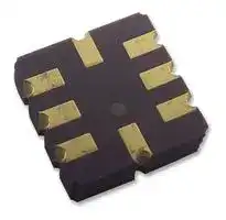


AD22035Z
MEMS Accelerometer, ± 18g, X, CLCC, 8 Pins, 100mV/g
- Manufacturer: ANALOG DEVICES
- Product type: MEMS Accelerometers
- SVHC: Lead (04-Feb-2026)
- No. of Pins: 8Pins
- Sensing Axis: X
- Product Range: -
- Qualification: -
- Sensitivity Max: 106mV/g
- Sensitivity Min: 94mV/g
- Sensitivity Typ: 100mV/g
- Output Interface: -
- Sensor Case Style: CLCC
- MEMS Sensor Output: Analogue
- Supply Voltage Max: 6V
- Supply Voltage Min: 3V
- Sensor Case / Package: CLCC
- Operating Temperature Max: 125°C
- Operating Temperature Min: -40°C
- Sensing Range - Accelerometer: ± 18g
| Delivery and price | |
|---|---|
| Units per pack | 250 |
| Price | 23.06 € |
| Current stock | 10+ |
| Lead time | 30 days |
**==> picture [159 x 45] intentionally omitted <==**

## **Precision ±1.7** _**g**_ **, ±5** _**g**_ **, ±18** _**g**_ **Single-/ Dual-Axis** _i_ **MEMS[®] Accelerometer**

## **Data Sheet**

## **ADXL103/ADXL203**

## **FEATURES**

**High performance, single-/dual-axis accelerometer on a single IC chip**

**5 mm × 5 mm × 2 mm LCC package 1 m** _**g**_ **resolution at 60 Hz**

**Low power: 700 μA at VS = 5 V (typical) High zero** _**g**_ **bias stability**

**High sensitivity accuracy −40°C to +125°C temperature range X and Y axes aligned to within 0.1° (typical) Bandwidth adjustment with a single capacitor Single-supply operation 3500** _**g**_ **shock survival**

**RoHS compliant Compatible with Sn/Pb- and Pb-free solder processes**

## **APPLICATIONS**

**Platform stabilization/leveling Navigation Alarms and motion detectors High accuracy, 2-axis tilt sensing Vibration monitoring and compensation Abuse event detection**

## **GENERAL DESCRIPTION**

The ADXL103/ADXL203 are high precision, low power, complete single- and dual-axis accelerometers with signal conditioned voltage outputs, all on a single, monolithic IC. The ADXL103/ ADXL203 measure acceleration with a full-scale range of ±1.7 _g_ , ±5 _g_ , or ±18 _g_ . The ADXL103/ADXL203 can measure both dynamic acceleration (for example, vibration) and static acceleration (for example, gravity).

The typical noise floor is 110 μ _g_ /√Hz, allowing signals below 1 m _g_ (0.06° of inclination) to be resolved in tilt sensing applications using narrow bandwidths (<60 Hz).

The user selects the bandwidth of the accelerometer using Capacitor CX and Capacitor CY at the XOUT and YOUT pins. Bandwidths of 0.5 Hz to 2.5 kHz can be selected to suit the application.

The ADXL103 and ADXL203 are available in a 5 mm × 5 mm × 2 mm, 8-terminal ceramic LCC package.

## **FUNCTIONAL BLOCK DIAGRAMS**

**==> picture [461 x 152] intentionally omitted <==**

**----- Start of picture text -----**<br>
+5V +5V<br>VS VS<br>ADXL103 ADXL203<br>CDC AC DEMOD OUTPUT CDC AC DEMOD OUTPUT OUTPUT<br>AMP AMP AMP AMP AMP<br>SENSOR SENSOR<br>RFILT RFILT RFILT<br>32kΩ 32kΩ 32kΩ<br>COM ST XOUT COM ST YOUT XOUT<br>CX CY CX<br>Figure 1.<br>03757-001<br>**----- End of picture text -----**<br>


**Document Feedback**

**Rev. F Document Feedback Information furnished by Analog Devices is believed to be accurate and reliable. However, no responsibility is assumed by Analog Devices for its use, nor for any infringements of patents or other rights of third parties that may result from its use. Specifications subject to change without notice. No license is granted by implication or otherwise under any patent or patent rights of Analog Devices. Trademarks and registered trademarks are the property of their respective owners.**

**One Technology Way, P.O. Box 9106, Norwood, MA 02062-9106, U.S.A. Tel: 781.329.4700 ©2004–2018 Analog Devices, Inc. All rights reserved. Technical Support www.analog.com**

**ADXL103/ADXL203**

**Data Sheet**

## **TABLE OF CONTENTS**

Features .............................................................................................. 1 Applications ....................................................................................... 1 General Description ......................................................................... 1 Functional Block Diagrams ............................................................. 1 Revision History ............................................................................... 2 Specifications ..................................................................................... 3 Absolute Maximum Ratings ............................................................ 4 ESD Caution .................................................................................. 4 Pin Configurations and Function Descriptions ........................... 5 Typical Performance Characteristics ............................................. 6 ADXL103 and ADXL203 .............................................................. 6 AD22293 ........................................................................................ 9 AD22035 and AD22037 ............................................................ 10 All Models ................................................................................... 12

Theory of Operation ...................................................................... 13 Performance ................................................................................ 13 Applications Information .............................................................. 14 Power Supply Decoupling ......................................................... 14 Setting the Bandwidth Using CX and CY ................................. 14 Self Test ........................................................................................ 14 Design Trade-Offs for Selecting Filter Characteristics: The Noise/Bandwidth Trade-Off ..................................................... 14 Using the ADXL103/ADXL203 with Operating Voltages Other than 5 V ............................................................................ 15 Using the ADXL203 as a Dual-Axis Tilt Sensor ........................ 15 Outline Dimensions ....................................................................... 16 Ordering Guide .......................................................................... 16

## **REVISION HISTORY**

## **5/2018—Rev. E to Rev. F**

Changes to Features Section and Applications Section ............... 1 Changes to Noise Parameter, Table 1 ............................................. 3 Changes to Ordering Guide .......................................................... 16 Deleted Automotive Products Section ......................................... 16

**1/2014—Rev. D to Rev. E** Changes to Ordering Guide .......................................................... 16

## **9/2011—Rev. C to Rev. D**

Added AD22293, AD22035, and AD22037 ............... Throughout Changes to Application Section and General Description Section ................................................................................................ 1 Changes to Table 1 ............................................................................ 3 Deleted Figure 13 and Figure 14: Renumbered Sequentially ..... 7 Deleted Figure 17 and Figure 22 ..................................................... 8 Added Figure 19 to Figure 24; Renumbered Sequentially .......... 9 Added Figure 25 to Figure 34........................................................ 10 Added All Models Section, Figure 35 to Figure 38 .................... 12 Changes to Figure 39 ...................................................................... 13 Changes to Ordering Guide .......................................................... 16 Changes to Automotive Products Section ................................... 16

## **4/2010—Rev. A to Rev. B**

Changes to Features Section ............................................................ 1 Updated Outline Dimensions ....................................................... 12 Changes to Ordering Guide .......................................................... 12

**2/2006—Rev. 0 to Rev. A** Changes to Features .......................................................................... 1 Changes to Table 1 ............................................................................. 3 Changes to Figure 2 ........................................................................... 4 Changes to Figure 3 and Figure 4 .................................................... 5 Changes to the Performance Section .............................................. 9

## **4/2004—Revision 0: Initial Version**

## **5/2010—Rev. B to Rev. C**

Changes to Figure 24 Caption ....................................................... 12 Added Automotive Products Section........................................... 12

Rev. F | Page 2 of 16

**Data Sheet**

**ADXL103/ADXL203**

## **SPECIFICATIONS**

TA = −40°C to +125°C, VS = 5 V, CX = CY = 0.1 µF, acceleration = 0 _g_ , unless otherwise noted. All minimum and maximum specifications are guaranteed. All typical specifications are not guaranteed.

**Table 1.**

|**Table 1.**||||||
|---|---|---|---|---|---|
|**Parameter**|**Test Conditions**|**ADXL103/ADXL203**<br>**Min**<br>**Typ**<br>**Max**|**AD22293**<br>**Min**<br>**Typ**<br>**Max**|**AD22035/AD22037**<br>**Min**<br>**Typ**<br>**Max**|**Unit**|
|SENSOR<br>Measurement Range1<br>Nonlinearity<br>Package Alignment Error<br>Alignment Error (ADXL203)<br>Cross-Axis Sensitivity|Each axis<br>% of full scale<br>X to Y sensor|±1.7<br>±0.2<br>±1.25<br>±1<br>±0.1<br>±1.5<br>±3|±5<br>±6<br>±0.2<br>±1.25<br>±1<br>±0.1<br>±1.5<br>±3|±18<br>±0.2<br>±1.25<br>±1<br>±0.1<br>±1.5<br>±3|_g_<br>%<br>Degrees<br>Degrees<br>%|
|SENSITIVITY (RATIOMETRIC)2<br>Sensitivity at XOUT, YOUT<br>Sensitivity Change Due to<br>Temperature3|Each axis<br>VS= 5 V<br>VS= 5 V|960<br>1000<br>1040<br>±0.3|293<br>312<br>331<br>±0.3|94<br>100<br>106<br>±0.3|mV/_g_<br>_%_|
|ZERO_g_BIAS LEVEL (RATIOMETRIC)<br>0_g_Voltage at XOUT, YOUT<br>Initial 0_g_Output Deviation<br>from Ideal<br>0_g_Offset vs. Temperature|Each axis<br>VS= 5 V<br>VS= 5 V, 25°C|2.4<br>2.5<br>2.6<br>±25<br>±0.1<br>±0.8|2.4<br>2.5<br>2.6<br>±50<br>±0.3<br>±1.8|2.4<br>2.5<br>2.6<br>±125<br>±1|V<br>m_g_<br>m_g_/°C|
|NOISE<br>Output Noise<br>Noise Density||1<br>3<br>110|0.4<br>130|0.2<br>230|mV rms<br>µ_g_/√Hz rms|
|FREQUENCY RESPONSE4<br>CX, CYRange5<br>RFILTTolerance<br>Sensor Resonant Frequency||0.002<br>10<br>24<br>32<br>40<br>5.5|0.002<br>10<br>24<br>32<br>40<br>5.5|0.002<br>10<br>24<br>32<br>40<br>5.5|µF<br>kΩ<br>kHz|
|SELF TEST6<br>Logic Input Low<br>Logic Input High<br>ST Input Resistance to GND<br>Output Change at XOUT, YOUT|ST 0 to ST 1|1<br>4<br>30<br>50<br>450<br>750<br>1100|1<br>4<br>30<br>50<br>125<br>250<br>375|1<br>4<br>30<br>50<br>60<br>80<br>100|V<br>V<br>kΩ<br>mV|
|OUTPUT AMPLIFIER<br>Output Swing Low<br>Output SwingHigh|No load<br>No load|0.05<br>0.2<br>4.5<br>4.8|0.05<br>0.2<br>4.5<br>4.8|0.05<br>0.2<br>4.5<br>4.8|V<br>V|
|POWER SUPPLY (VDD)<br>Operating Voltage Range<br>Quiescent Supply Current<br>Turn-On Time7||3<br>6<br>0.7<br>1.1<br>20|3<br>6<br>0.7<br>1.1<br>20|3<br>6<br>0.7<br>1.1<br>20|V<br>mA<br>ms|


- 1 Guaranteed by measurement of initial offset and sensitivity.

- 2 Sensitivity is essentially ratiometric to VS. For VS = 4.75 V to 5.25 V, sensitivity is 186 mV/V/ _g_ to 215 mV/V/ _g_ .

- 3 Defined as the output change from ambient-to-maximum temperature or ambient-to-minimum temperature.

4 Actual frequency response controlled by user-supplied external capacitor (CX, CY).

5 Bandwidth = 1/(2 × π × 32 kΩ × C). For CX, CY = 0.002 µF, bandwidth = 2500 Hz. For CX, CY = 10 µF, bandwidth = 0.5 Hz. Minimum/maximum values are not tested. 6 Self-test response changes cubically with VS.

- 7 Larger values of CX, CY increase turn-on time. Turn-on time is approximately 160 × CX or CY + 4 ms, where CX, CY are in µF.

Rev. F | Page 3 of 16

**ADXL103/ADXL203**

**Data Sheet**

## **ABSOLUTE MAXIMUM RATINGS**

**Table 3. Package Characteristics**

## **Table 2.**

|**Table 2**||**ae . acage arac**|**ae . acage arac**|**erscs**|||
|---|---|---|---|---|---|---|
|**.**|**Rating**<br>3500_g_<br>3500_g_<br>1.2 m<br>−0.3 V to +7.0 V<br>(COM − 0.3 V) to<br>(VS+ 0.3 V)<br>Indefinite<br>−55°C to +125°C<br>−65°C to +150°C|**Package Type **||**θJA**|**θJC**|**Device Weight**|
|**Parameter**|**Rating**||||||
|||8-Terminal Ceramic LCC||120°C/W|20°C/W|<br><1.0gram|
|Acceleration (Any Axis, Unpowered)<br>Acceleration (Any Axis, Powered)<br>Drop Test (Concrete Surface)<br>VS<br>All Other Pins<br>Output Short-Circuit Duration<br>(Any Pin to Common)<br>Temperature Range (Powered)<br>Temperature Range (Storage)|3500_g_<br>3500_g_<br>1.2 m<br>−0.3 V to +7.0 V<br>(COM − 0.3 V) to<br>(VS+ 0.3 V)<br>Indefinite<br>−55°C to +125°C<br>−65°C to +150°C||||||
|||**ESD CAUTION**|||||
||||||||
||||||||


Stresses at or above those listed under Absolute Maximum Ratings may cause permanent damage to the product. This is a stress rating only; functional operation of the product at these or any other conditions above those indicated in the operational section of this specification is not implied. Operation beyond the maximum operating conditions for extended periods may affect product reliability.

|**TEMPERATURE**<br>**TP**<br>**TL**<br>**Table 4. Solder Profile Parameters**||||||||
|---|---|---|---|---|---|---|---|
||||||**t**~~**P**~~|||
||**RA**|||**MP-UP**||**tL**||
||**TSMAX**|||||||
|||||||||
||**TSMIN**|||||||
|||**tS**<br>**PREHEAT**||||||
||||||**RAMP-D**|**OW**||
|||||||||
|||**t25°C TO PEA**||||||
|||||||||
|**Profile Feature**|||**Test Condition**|||||
||||**Sn63/Pb37**||||**Pb-Free**|
|Average RampRate (TLto TP)|||3°C/second maximum||||3°C/second maximum|
|Preheat<br>Minimum Temperature (TSMIN)<br>Maximum Temperature (TSMAX)<br>Time (TSMINto TSMAX) (tS)|||100°C<br>150°C<br>60 seconds to 120 seconds||||150°C<br>200°C<br>60 seconds to 150 seconds|
|TSMAXto TL<br>Ramp-UpRate|||3°C/second||||3°C/second|
|Time Maintained Above Liquidous (TL)<br>Liquidous Temperature (TL)<br>Time (tL)|||183°C<br>60 seconds to 150 seconds||||217°C<br>60 seconds to 150 seconds|
|Peak Temperature (TP)|||240°C + 0°C/−5°C||||260°C + 0°C/−5°C|
|Time Within 5°C of Actual Peak Temperature (tP)|||10 seconds to 30 seconds||||20 seconds to 40 seconds|
|Ramp-Down Rate|||6°C/second maximum||||6°C/second maximum|
|Time 25°C to Peak Temperature|||6 minutes maximum||||8 minutes maximum|


Rev. F | Page 4 of 16

**Data Sheet**

**ADXL103/ADXL203**

## **PIN CONFIGURATIONS AND FUNCTION DESCRIPTIONS**

## **ADXL103**

**==> picture [40 x 14] intentionally omitted <==**

**----- Start of picture text -----**<br>
TOP VIEW<br>(Not to Scale)<br>**----- End of picture text -----**<br>


**==> picture [91 x 63] intentionally omitted <==**

**----- Start of picture text -----**<br>
VS<br>8<br>ST 1 7 XOUT<br>NC 2 +X 6 NC<br>COM 3 5 NC<br>4<br>NC 03757-002<br>**----- End of picture text -----**<br>


## **NOTES**

**1. NC = NO CONNECT. DO NOT CONNECT TO THIS PIN.**

_Figure 3. ADXL103 Pin Configuration_

**==> picture [40 x 24] intentionally omitted <==**

**----- Start of picture text -----**<br>
ADXL203<br>TOP VIEW<br>(Not to Scale)<br>**----- End of picture text -----**<br>


**==> picture [91 x 63] intentionally omitted <==**

**----- Start of picture text -----**<br>
VS<br>8<br>ST 1 7 XOUT<br>+Y<br>NC 2 6 YOUT<br>+X<br>COM 3 5 NC<br>4<br>NC 03757-003<br>**----- End of picture text -----**<br>


## **NOTES**

## **1. NC = NO CONNECT. DO NOT CONNECT TO THIS PIN.**

_Figure 4. ADXL203 Pin Configuration_

**Table 5. ADXL103 Pin Function Descriptions**

**Table 6. ADXL203 Pin Function Descriptions**

|**Pin No.**|**Mnemonic**|**Description**<br>Self Test<br>Do Not Connect<br>Common<br>Do Not Connect<br>Do Not Connect<br>Do Not Connect<br>X Channel Output<br>3 V to 6 V|**Pin No.**|**Mnemonic**|**Description**|
|---|---|---|---|---|---|
|1<br>2<br>3<br>4<br>5<br>6<br>7<br>8|ST<br>NC<br>COM<br>NC<br>NC<br>NC<br>XOUT<br>VS||1<br>2<br>3<br>4<br>5<br>6<br>7<br>8|ST<br>NC<br>COM<br>NC<br>NC<br>YOUT<br>XOUT<br>VS|Self Test<br>Do Not Connect<br>Common<br>Do Not Connect<br>Do Not Connect<br>Y Channel Output<br>X Channel Output<br>3 V to 6 V|


Rev. F | Page 5 of 16

**ADXL103/ADXL203**

**Data Sheet**

## **TYPICAL PERFORMANCE CHARACTERISTICS**

## **ADXL103 AND ADXL203**

VS = 5 V for all graphs, unless otherwise noted.

**==> picture [207 x 175] intentionally omitted <==**

**----- Start of picture text -----**<br>
25<br>20<br>15<br>10<br>5<br>0<br>ZERO  g  BIAS (V)<br>PERCENT OF POPULATION (%)<br>03757-010<br>–0.10 –0.08 –0.06 –0.04 –0.02 0 0.02 0.04 0.06 0.08 0.10<br>**----- End of picture text -----**<br>


_Figure 5. X-Axis Zero_ g _Bias Deviation from Ideal at 25°C_

**==> picture [207 x 392] intentionally omitted <==**

**----- Start of picture text -----**<br>
30<br>25<br>20<br>15<br>10<br>5<br>0<br>TEMPERATURE COEFFICIENT (m g /°C)<br>Figure 6. X-Axis Zero  g  Bias Temperature Coefficient<br>40<br>35<br>30<br>25<br>20<br>15<br>10<br>5<br>0<br>SENSITIVITY (V/ g)<br>Figure 7. X-Axis Sensitivity at 25°C<br>PERCENT OF POPULATION (%)<br>03757-011<br>–0.80 –0.70 –0.60 –0.50 –0.40 –0.30 –0.20 –0.10 0 0.10 0.20 0.30 0.40 0.50 0.60 0.70 0.80<br>PERCENT OF POPULATION (%)<br>03757-012<br>0.94 0.95 0.96 0.97 0.98 0.99 1.00 1.01 1.02 1.03 1.04 1.05 1.06<br>**----- End of picture text -----**<br>


**==> picture [207 x 598] intentionally omitted <==**

**----- Start of picture text -----**<br>
30<br>25<br>20<br>15<br>10<br>5<br>0<br>ZERO  g  BIAS (V)<br>Figure 8. Y-Axis Zero  g  Bias Deviation from Ideal at 25°C<br>25<br>20<br>15<br>10<br>5<br>0<br>TEMPERATURE COEFFICIENT (m g /°C)<br>Figure 9. Y-Axis Zero  g  Bias Temperature Coefficient<br>40<br>35<br>30<br>25<br>20<br>15<br>10<br>5<br>0<br>SENSITIVITY (V/ g)<br>Figure 10. Y-Axis Sensitivity at 25°C<br>PERCENT OF POPULATION (%)<br>03757-013<br>–0.10 –0.08 –0.06 –0.04 –0.02 0 0.02 0.04 0.06 0.08 0.10<br>PERCENT OF POPULATION (%)<br>03757-014<br>–0.80 –0.70 –0.60 –0.50 –0.40 –0.30 –0.20 –0.10 0 0.10 0.20 0.30 0.40 0.50 0.60 0.70 0.80<br>PERCENT OF POPULATION (%)<br>03757-015<br>0.94 0.95 0.96 0.97 0.98 0.99 1.00 1.01 1.02 1.03 1.04 1.05 1.06<br>**----- End of picture text -----**<br>


Rev. F | Page 6 of 16

**ADXL103/ADXL203**

## **Data Sheet**

**==> picture [215 x 375] intentionally omitted <==**

**----- Start of picture text -----**<br>
2.60<br>2.58<br>2.56<br>2.54<br>2.52<br>2.50<br>2.48<br>2.46<br>2.44<br>2.42<br>2.40<br>TEMPERATURE (°C)<br>Figure 11. Zero  g  Bias vs. Temperature; Devices Soldered to PCB<br>50<br>45<br>40<br>35<br>30<br>25<br>20<br>15<br>10<br>5<br>0<br>60 70 80 90 100 110 120 130 140 150<br>X AXIS NOISE DENSITY (m g /√Hz)<br>Figure 12. X-Axis Noise Density at 25°C<br>) g<br>VOLTAGE (1V/<br>03757-004<br>–50 –40 –30 –20 –10 0 10 20 30 40 50 60 70 80 90 100 110 120 130<br>PERCENT OF POPULATION (%)<br>03757-007<br>**----- End of picture text -----**<br>


**==> picture [215 x 375] intentionally omitted <==**

**----- Start of picture text -----**<br>
1.03<br>1.02<br>1.01<br>1.00<br>0.99<br>0.98<br>0.97<br>TEMPERATURE (°C)<br>Figure 13. Sensitivity vs. Temperature; Devices Soldered to PCB<br>50<br>45<br>40<br>35<br>30<br>25<br>20<br>15<br>10<br>5<br>0<br>60 70 80 90 100 110 120 130 140 150<br>Y AXIS NOISE DENSITY (m g /√Hz)<br>Figure 14. Y-Axis Noise Density at 25°C<br>) g<br>SENSITIVITY (V/<br>03757-016<br>–50 –40 –30 –20 –10 0 10 20 30 40 50 60 70 80 90 100 110 120 130<br>PERCENT OF POPULATION (%)<br>03757-008<br>**----- End of picture text -----**<br>


Rev. F | Page 7 of 16

**ADXL103/ADXL203**

**Data Sheet**

**==> picture [490 x 375] intentionally omitted <==**

**----- Start of picture text -----**<br>
45 45<br>40 40<br>35 35<br>30 30<br>25 25<br>20 20<br>15 15<br>10 10<br>5 5<br>0 0<br>SELF-TEST OUTPUT (V) SELF-TEST OUTPUT (V)<br>Figure 15. X-Axis Self-Test Response at 25°C  Figure 17. Y-Axis Self-Test Response at 25°C<br>0.90 100<br>0.85 90 5V<br>80<br>0.80<br>70 3V<br>0.75 60<br>0.70 50<br>40<br>0.65<br>30<br>0.60<br>20<br>0.55<br>10<br>0.50 0<br>TEMPERATURE (°C)<br>PERCENT OF POPULATION (%) PERCENT OF POPULATION (%)<br>03757-017 03757-019<br>0.40 0.45 0.50 0.55 0.60 0.65 0.70 0.75 0.80 0.85 0.90 0.95 1.00 0.40 0.45 0.50 0.55 0.60 0.65 0.70 0.75 0.80 0.85 0.90 0.95 1.00<br>) g<br>VOLTAGE (1V/<br>PERCENT OF POPULATION (%)<br>03757-103<br>–50 –40 –30 –20 –10 0 10 20 30 40 50 60 70 80 90 100 110 120 130 200 300 400 500 600 700 800 900 1000<br>**----- End of picture text -----**<br>


**==> picture [211 x 173] intentionally omitted <==**

**----- Start of picture text -----**<br>
100<br>90 5V<br>80<br>70 3V<br>60<br>50<br>40<br>30<br>20<br>10<br>0<br>CURRENT (µA)<br>PERCENT OF POPULATION (%)<br>03757-018<br>200 300 400 500 600 700 800 900 1000<br>**----- End of picture text -----**<br>


_Figure 18. Supply Current at 25°C_

_Figure 16. Self-Test Response vs. Temperature_

Rev. F | Page 8 of 16

**ADXL103/ADXL203**

## **Data Sheet**

## **AD22293**

**==> picture [211 x 186] intentionally omitted <==**

**----- Start of picture text -----**<br>
60<br>50<br>40<br>30<br>20<br>10<br>0<br>ZERO  g  BIAS (V)<br>Figure 19. X-Axis Zero  g  Bias at 25°C<br>PERCENT OF POPULATION (%)<br>2.43 2.44 2.45 2.46 2.47 2.48 2.49 2.50 2.51 2.52 2.53 2.54 2.55 2.56 2.57<br>03757-117<br>**----- End of picture text -----**<br>


**==> picture [213 x 396] intentionally omitted <==**

**----- Start of picture text -----**<br>
25<br>20<br>15<br>10<br>5<br>0<br>TEMPERATURE COEFFICIENT (m g /°C)<br>Figure 20. X-Axis Zero  g  Bias Temperature Coefficient<br>90<br>80<br>70<br>60<br>50<br>40<br>30<br>20<br>10<br>0<br>SENSITIVITY (V/ g )<br>Figure 21. X-Axis Sensitivity at 25°C<br>PERCENT OF POPULATION (%)<br>–1.2 –1.0 –0.8 –0.6 –0.4 –0.2 0 0.2 0.4 0.6 0.8 1.0 1.2 03757-118<br>PERCENT OF POPULATION (%)<br>0.287 0.297 0.307 0.317 0.327 0.337 0.347 0.357 0.367 0.377 0.387<br>03757-021<br>**----- End of picture text -----**<br>


**==> picture [211 x 171] intentionally omitted <==**

**----- Start of picture text -----**<br>
70<br>60<br>50<br>40<br>30<br>20<br>10<br>0<br>ZERO  g  BIAS (V)<br>PERCENT OF POPULATION (%)<br>2.43 2.44 2.45 2.46 2.47 2.48 2.49 2.50 2.51 2.52 2.53 2.54 2.55 2.56 2.57 03757-119<br>**----- End of picture text -----**<br>


_Figure 22. Y-Axis Zero_ g _Bias at 25°C_

**==> picture [212 x 188] intentionally omitted <==**

**----- Start of picture text -----**<br>
25<br>20<br>15<br>10<br>5<br>0<br>TEMPERATURE COEFFICIENT (m g /°C)<br>Figure 23. Y-Axis Zero  g  Bias Temperature Coefficient<br>PERCENT OF POPULATION (%)<br>–1.2 –1.0 –0.8 –0.6 –0.4 –0.2 0 0.2 0.4 0.6 0.8 1.0 1.2 03757-020<br>**----- End of picture text -----**<br>


**==> picture [215 x 189] intentionally omitted <==**

**----- Start of picture text -----**<br>
80<br>70<br>60<br>50<br>40<br>30<br>20<br>10<br>0<br>SENSITIVITY (V/ g )<br>Figure 24. Y-Axis Sensitivity at 25°C<br>PERCENT OF POPULATION (%)<br>0.287 0.297 0.307 0.317 0.327 0.337 0.347 0.357 0.367 0.377 0.387<br>03757-022<br>**----- End of picture text -----**<br>


Rev. F | Page 9 of 16

**ADXL103/ADXL203**

**Data Sheet**

**==> picture [118 x 8] intentionally omitted <==**

**----- Start of picture text -----**<br>
AD22035 AND AD22037<br>**----- End of picture text -----**<br>


**==> picture [211 x 185] intentionally omitted <==**

**----- Start of picture text -----**<br>
60<br>50<br>40<br>30<br>20<br>10<br>0<br>ZERO  g  BIAS (mV)<br>Figure 25. X-Axis Zero  g  Bias Deviation from Ideal at 25°C<br>PERCENT OF POPULATION<br>–50 –40 –30 –20 –10 0 10 20 30 40 50<br>03757-105<br>**----- End of picture text -----**<br>


**==> picture [212 x 390] intentionally omitted <==**

**----- Start of picture text -----**<br>
35<br>30<br>25<br>20<br>15<br>10<br>5<br>0<br>TEMPERATURE COEFFICIENT (m g /°C)<br>Figure 26. X-Axis Zero  g  Bias Temperature Coefficient<br>25<br>20<br>15<br>10<br>5<br>0<br>SENSITIVITY (mV/ g)<br>Figure 27. X-Axis Sensitivity at 25°C<br>PERCENT OF POPULATION<br>–3.0 –2.5 –2.0 –1.5 –1.0 –0.5 0 0.5 1.0 1.5 2.0 2.5 3.0 3.5 03757-106<br>PERCENT OF POPULATION<br>97 98 99 100 101 102 103 03757-107<br>**----- End of picture text -----**<br>


**==> picture [211 x 185] intentionally omitted <==**

**----- Start of picture text -----**<br>
60<br>50<br>40<br>30<br>20<br>10<br>0<br>ZERO  g  BIAS (mV)<br>Figure 28. Y-Axis Zero  g  Bias Deviation from Ideal at 25°C<br>PERCENT OF POPULATION<br>–50 –40 –30 –20 –10 0 10 20 30 40 50 03757-108<br>**----- End of picture text -----**<br>


**==> picture [211 x 389] intentionally omitted <==**

**----- Start of picture text -----**<br>
35<br>30<br>25<br>20<br>15<br>10<br>5<br>0<br>TEMPERATURE COEFFICIENT (m g /°C)<br>Figure 29. Y-Axis Zero  g  Bias Temperature Coefficient<br>25<br>20<br>15<br>10<br>5<br>0<br>SENSITIVITY (mV/ g)<br>Figure 30. Y-Axis Sensitivity at 25°C<br>PERCENT OF POPULATION<br>–3.0 –2.5 –2.0 –1.5 –1.0 –0.5 0 0.5 1.0 1.5 2.0 2.5 3.0 03757-009<br>PERCENT OF POPULATION<br>97 98 99 100 101 102 103 03757-110<br>**----- End of picture text -----**<br>


Rev. F | Page 10 of 16

**ADXL103/ADXL203**

## **Data Sheet**

**==> picture [211 x 190] intentionally omitted <==**

**----- Start of picture text -----**<br>
40<br>35<br>30<br>25<br>20<br>15<br>10<br>5<br>0<br>SELF-TEST OUTPUT (V)<br>Figure 31. X-Axis Self Test Response at 25°C<br>PERCENT OF POPULATION<br>0.060 0.065 0.070 0.075 0.080 0.085 0.090 0.095 0.100<br>03757-111<br>**----- End of picture text -----**<br>


**==> picture [498 x 393] intentionally omitted <==**

**----- Start of picture text -----**<br>
40 45<br>35 40<br>35<br>30<br>30<br>25<br>25<br>20<br>20<br>15<br>15<br>10<br>10<br>5 5<br>0 0<br>SELF-TEST OUTPUT (V) SELF-TEST OUTPUT (V)<br>Figure 31. X-Axis Self Test Response at 25°C  Figure 33. Y-Axis Self Test Response at 25°C<br>101.0 90<br>80 25°C 105°C<br>100.5<br>70<br>100.0<br>60<br>99.5 50<br>40<br>99.0<br>30<br>98.5<br>20<br>98.0<br>10<br>97.5 0<br>–50 –25 0 25 50 75 100 125<br>TEMPERATURE (°C)<br>CURRENT (µA)<br>Figure 32. Sensitivity vs. Temperature; Devices Soldered to PCB  Figure 34. Supply Current vs. Temperature<br>PERCENT OF POPULATION PERCENT OF POPULATION<br>0.060 0.065 0.070 0.075 0.080 0.085 0.090 0.095 0.100 0.060 0.065 0.070 0.075 0.080 0.085 0.090 0.095 0.100<br>03757-111 03757-114<br>SENSITIVITY (mV)<br>PERCENT OF POPULATION<br>680 700 720 740 760 780 800 820 840 860 880 900 920 940 960<br>03757-112<br>03757-113<br>**----- End of picture text -----**<br>


Rev. F | Page 11 of 16

**ADXL103/ADXL203**

**Data Sheet**

## **ALL MODELS**

**==> picture [498 x 382] intentionally omitted <==**

**----- Start of picture text -----**<br>
40 40<br>35 35<br>30 30<br>25 25<br>20 20<br>15 15<br>10 10<br>5 5<br>0 0<br>PERCENT SENSITIVITY (%) PERCENT SENSITIVITY (%)<br>Figure 35. Z vs. X Cross-Axis Sensitivity  Figure 37. Z vs. Y Cross-Axis Sensitivity<br>0.9<br>0.8<br>VS = 5V<br>0.7<br>0.6<br>0.5<br>VS = 3V<br>0.4<br>0.3<br>–50 0 50 100 150<br>TEMPERATURE (°C) TIME<br>Figure 36. Supply Current vs. Temperature  Figure 38. Turn-On Time; CX, CY = 0.1 μF, Time Scale = 2 ms/DIV<br>PERCENT OF POPULATION (%) PERCENT OF POPULATION (%)<br>–5.0 –4.0 –3.0 –2.0 –1.0 0 1.0 2.0 3.0 4.0 5.0 –5.0 –4.0 –3.0 –2.0 –1.0 0 1.0 2.0 3.0 4.0 5.0<br>09781-023 09781-026<br>CURRENT (mA) VOLTAGE (V)<br>09781-027<br>09781-024<br>**----- End of picture text -----**<br>


Rev. F | Page 12 of 16

**Data Sheet**

**ADXL103/ADXL203**

## **THEORY OF OPERATION**

The ADXL103/ADXL203 are complete acceleration measurement systems on a single, monolithic IC. The ADXL103 is a singleaxis accelerometer, and the ADXL203 is a dual-axis accelerometer. Both devices contain a polysilicon surface micromachined sensor and signal conditioning circuitry to implement an open-loop acceleration measurement architecture. The output signals are analog voltages that are proportional to acceleration. The ADXL103/ADXL203 are capable of measuring both positive and negative accelerations from ±1.7 _g_ to at least ±18 _g_ . The accelerometer can measure static acceleration forces, such as gravity, allowing it to be used as a tilt sensor.

The sensor is a surface micromachined polysilicon structure built on top of the silicon wafer. Polysilicon springs suspend the structure over the surface of the wafer and provide a resistance against acceleration forces. Deflection of the structure is measured using a differential capacitor that consists of independent fixed plates and plates attached to the moving mass. The fixed plates are driven by 180° out-of-phase square waves. Acceleration deflects the beam and unbalances the differential capacitor, resulting in an output square wave whose amplitude is proportional to acceleration. Phase-sensitive demodulation techniques then rectify the signal and determine the direction of the acceleration.

The output of the demodulator is amplified and brought off-chip through a 32 kΩ resistor. At this point, the user can set the signal bandwidth of the device by adding a capacitor. This filtering improves measurement resolution and helps prevent aliasing.

## **PERFORMANCE**

Rather than using additional temperature compensation circuitry, innovative design techniques ensure high performance is built in. As a result, there is essentially no quantization error or nonmonotonic behavior, and temperature hysteresis is very low (typically less than 10 m _g_ over the −40°C to +125°C temperature range).

Figure 11 shows the 0 _g_ output performance of eight devices (x and y axes) over a −40°C to +125°C temperature range.

Figure 13 demonstrates the typical sensitivity shift over temperature for VS = 5 V. Sensitivity stability is optimized for VS = 5 V but is still very good over the specified range; it is typically better than ±1% over temperature at VS = 3 V.

**==> picture [237 x 191] intentionally omitted <==**

**----- Start of picture text -----**<br>
PIN 8<br>XOUT = –1 g<br>YOUT = 0 g<br>PIN 8 TOP VIEW PIN 8<br>XOUT = 0 g (Not to Scale) XOUT = 0 g<br>YOUT = +1 g YOUT = –1 g<br>XOUT = 0 g<br>YOUT = 0 g<br>PIN 8<br>XOUT = +1 g<br>YOUT = 0 g<br>EARTH’S SURFACE<br>03757-028<br>**----- End of picture text -----**<br>


_Figure 39. Output Response vs. Orientation_

Rev. F | Page 13 of 16

**Data Sheet**

## **ADXL103/ADXL203**

## **APPLICATIONS INFORMATION POWER SUPPLY DECOUPLING**

For most applications, a single 0.1 µF capacitor, CDC, adequately decouples the accelerometer from noise on the power supply. However, in some cases, particularly where noise is present at the 140 kHz internal clock frequency (or any harmonic thereof), noise on the supply can cause interference on the ADXL103/ ADXL203 output. If additional decoupling is needed, a 100 Ω (or smaller) resistor or ferrite beads can be inserted in the supply line of the ADXL103/ADXL203. Additionally, a larger bulk bypass capacitor (in the 1 µF to 22 µF range) can be added in parallel to CDC.

## **SETTING THE BANDWIDTH USING CX AND CY**

The ADXL103/ADXL203 has provisions for band limiting the XOUT and YOUT pins. Capacitors must be added at these pins to implement low-pass filtering for antialiasing and noise reduction. The equation for the 3 dB bandwidth is

_f_ –3 _dB_ = 1/(2π(32 kΩ) × _C_ ( _X_ , _Y_ ))

or more simply,

_f_ –3 _dB_ = 5 µF/ _C_ ( _X_ , _Y_ )

The tolerance of the internal resistor (RFILT) can vary typically as much as ±25% of its nominal value (32 kΩ); thus, the bandwidth varies accordingly. A minimum capacitance of 2000 pF for CX and CY is required in all cases.

## **DESIGN TRADE-OFFS FOR SELECTING FILTER CHARACTERISTICS: THE NOISE/BANDWIDTH TRADE-OFF**

The accelerometer bandwidth selected ultimately determines the measurement resolution (smallest detectable acceleration). Filtering can lower the noise floor, improving the resolution of the accelerometer. Resolution is dependent on the analog filter bandwidth at XOUT and YOUT.

The output of the ADXL103/ADXL203 has a typical bandwidth of 2.5 kHz. The user must filter the signal at this point to limit aliasing errors. The analog bandwidth must be no more than half the analog-to-digital sampling frequency to minimize aliasing. The analog bandwidth can be further decreased to reduce noise and improve resolution.

The ADXL103/ADXL203 noise has the characteristics of white Gaussian noise, which contributes equally at all frequencies and is described in terms of µ _g_ /√Hz (that is, the noise is proportional to the square root of the accelerometer bandwidth). Limit bandwidth to the lowest frequency needed by the application to maximize the resolution and dynamic range of the accelerometer.

With the single-pole roll-off characteristic, the typical noise of the ADXL103/ADXL203 is determined by

_rmsNoise_ = (110 µ _g_ /√Hz) × ( BW × 6.1

At 100 Hz, the noise is

**Table 7. Filter Capacitor Selection, CX and CY**

|**Bandwidth (Hz)**|**Capacitor (µF)**|
|---|---|
|1<br>10<br>50<br>100<br>200<br>500|4.7<br>0.47<br>0.10<br>0.05<br>0.027<br>0.01|


## **SELF TEST**

The ST pin controls the self test feature. When this pin is set to VS, an electrostatic force is exerted on the beam of the accelerometer. The resulting movement of the beam allows the user to test if the accelerometer is functional. The typical change in output is 750 m _g_ (corresponding to 750 mV). This pin can be left opencircuit or connected to common in normal use.

Never expose the ST pin to voltages greater than VS + 0.3 V. If the system design is such that this condition cannot be guaranteed (that is, multiple supply voltages are present), a low VF clamping diode between ST and VS is recommended.

_rmsNoise_ = (110 µ _g_ /√Hz) × ( 100 × 6.1 ) = 1.4 m _g_

Often, the peak value of the noise is desired. Peak-to-peak noise can only be estimated by statistical methods. Table 8 is useful for estimating the probabilities of exceeding various peak values, given the rms value.

**Table 8. Estimation of Peak-to-Peak Noise**

|**Peak-to-Peak Value**|**% of Time That Noise Exceeds**<br>**Nominal Peak-to-Peak Value**|
|---|---|
|2 × rms<br>4 × rms<br>6 × rms<br>8 × rms|32<br>4.6<br>0.27<br>0.006|


Peak-to-peak noise values give the best estimate of the uncertainty in a single measurement; peak-to-peak noise is estimated by 6 × rms. Table 9 gives the typical noise output of the ADXL103/ ADXL203 for various CX and CY values.

**Table 9. Filter Capacitor Selection (CX, CY)**

|**Bandwidth (Hz)**|**CX, CY **<br>**(µF)**|**RMS Noise**<br>**(m****_g_) **|**Peak-to-Peak Noise**<br>**Estimate (m****_g_) **|
|---|---|---|---|
|10<br>50<br>100<br>500|0.47<br>0.1<br>0.047<br>0.01|0.4<br>1.0<br>1.4<br>3.1|2.6<br>6<br>8.4<br>18.7|


Rev. F | Page 14 of 16

**Data Sheet**

**ADXL103/ADXL203**

## **USING THE ADXL103/ADXL203 WITH OPERATING VOLTAGES OTHER THAN 5 V**

The ADXL103/ADXL203 is tested and specified at VS = 5 V; however, it can be powered with VS as low as 3 V or as high as 6 V. Some performance parameters change as the supply voltage is varied.

The ADXL103/ADXL203 output is ratiometric, so the output sensitivity (or scale factor) varies proportionally to the supply voltage. At VS = 3 V, the output sensitivity is typically 560 mV/ _g_ .

The zero _g_ bias output is also ratiometric, so the zero _g_ output is nominally equal to VS/2 at all supply voltages.

The output noise is not ratiometric but is absolute in volts; therefore, the noise density decreases as the supply voltage increases. This is because the scale factor (mV/ _g_ ) increases while the noise voltage remains constant. At VS = 3 V, the noise density is typically 190 μ _g_ /√Hz.

Self test response in _g_ is roughly proportional to the square of the supply voltage. However, when ratiometricity of sensitivity is factored in with supply voltage, self test response in volts is roughly proportional to the cube of the supply voltage. So at VS = 3 V, the self test response is approximately equivalent to 150 mV or equivalent to 270 m _g_ (typical).

The supply current decreases as the supply voltage decreases. Typical current consumption at VDD = 3 V is 450 μA.

## **USING THE ADXL203 AS A DUAL-AXIS TILT SENSOR**

One of the most popular applications of the ADXL203 is tilt measurement. An accelerometer uses the force of gravity as an input vector to determine the orientation of an object in space.

An accelerometer is most sensitive to tilt when its sensitive axis is perpendicular to the force of gravity, that is, parallel to the earth’s surface. At this orientation, its sensitivity to changes in tilt is highest. When the accelerometer is oriented on axis to gravity, that is, near its +1 _g_ or –1 _g_ reading, the change in output acceleration per degree of tilt is negligible. When the accelerometer is perpendicular to gravity, its output changes nearly 17.5 m _g_ per degree of tilt. At 45°, its output changes at only 12.2 m _g_ per degree, and resolution declines.

## _**Dual-Axis Tilt Sensor: Converting Acceleration to Tilt**_

When the accelerometer is oriented so both its x-axis and y-axis are parallel to the earth’s surface, it can be used as a 2-axis tilt sensor with a roll axis and a pitch axis. After the output signal from the accelerometer is converted to an acceleration that varies between –1 _g_ and +1 _g_ , the output tilt in degrees is calculated as

_PITCH_ = _ASIN_ ( _AX_ /1 _g_ )

_ROLL_ = _ASIN_ ( _AY_ /1 _g_ )

Be sure to account for overranges. It is possible for the accelerometers to output a signal greater than ±1 _g_ due to vibration, shock, or other accelerations.

Rev. F | Page 15 of 16

**ADXL103/ADXL203**

**Data Sheet**

## **OUTLINE DIMENSIONS**

|**ORDERING GUIDE**|**R**<br>**(4**|**0**<br>|**.180**<br>|**.180**<br>|**0.20**<br>|**BOTTOM VIEW**<br>**DETAIL A**<br>**(OPTION 2)**<br>**1**<br>**3**<br>**5**<br>**7**<br>**VIEW**<br>**0.075 REF**<br>**3**<br>**7 SQ**<br>**3**<br>**0.020**<br>**0.015**<br>**0.010**<br>**(R 4 PLCS)**<br>**0.087**<br>**0.078**<br>**0.069**<br>**0.008**<br>**0.006**<br>**0.004**<br>**0.077**<br>**0.070**<br>**0.063**<br>**0.054**<br>**0.050**<br>**0.046**<br>**0.030**<br>**0.025**<br>**0.020**<br>**0.019 SQ**<br>**R 0.008**<br>**(8 PLCS)**<br>_Figure 40. 8-Terminal Ceramic Leadless Chip Carrier [LCC]_<br>_(E-8-1)_<br>_Dimensions shown in inches_|**BOTTOM VIEW**<br>**DETAIL A**<br>**(OPTION 2)**<br>**1**<br>**3**<br>**5**<br>**7**<br>**VIEW**<br>**0.075 REF**<br>**3**<br>**7 SQ**<br>**3**<br>**0.020**<br>**0.015**<br>**0.010**<br>**(R 4 PLCS)**<br>**0.087**<br>**0.078**<br>**0.069**<br>**0.008**<br>**0.006**<br>**0.004**<br>**0.077**<br>**0.070**<br>**0.063**<br>**0.054**<br>**0.050**<br>**0.046**<br>**0.030**<br>**0.025**<br>**0.020**<br>**0.019 SQ**<br>**R 0.008**<br>**(8 PLCS)**<br>_Figure 40. 8-Terminal Ceramic Leadless Chip Carrier [LCC]_<br>_(E-8-1)_<br>_Dimensions shown in inches_|**BOTTOM VIEW**<br>**DETAIL A**<br>**(OPTION 2)**<br>**1**<br>**3**<br>**5**<br>**7**<br>**VIEW**<br>**0.075 REF**<br>**3**<br>**7 SQ**<br>**3**<br>**0.020**<br>**0.015**<br>**0.010**<br>**(R 4 PLCS)**<br>**0.087**<br>**0.078**<br>**0.069**<br>**0.008**<br>**0.006**<br>**0.004**<br>**0.077**<br>**0.070**<br>**0.063**<br>**0.054**<br>**0.050**<br>**0.046**<br>**0.030**<br>**0.025**<br>**0.020**<br>**0.019 SQ**<br>**R 0.008**<br>**(8 PLCS)**<br>_Figure 40. 8-Terminal Ceramic Leadless Chip Carrier [LCC]_<br>_(E-8-1)_<br>_Dimensions shown in inches_|**BOTTOM VIEW**<br>**DETAIL A**<br>**(OPTION 2)**<br>**1**<br>**3**<br>**5**<br>**7**<br>**VIEW**<br>**0.075 REF**<br>**3**<br>**7 SQ**<br>**3**<br>**0.020**<br>**0.015**<br>**0.010**<br>**(R 4 PLCS)**<br>**0.087**<br>**0.078**<br>**0.069**<br>**0.008**<br>**0.006**<br>**0.004**<br>**0.077**<br>**0.070**<br>**0.063**<br>**0.054**<br>**0.050**<br>**0.046**<br>**0.030**<br>**0.025**<br>**0.020**<br>**0.019 SQ**<br>**R 0.008**<br>**(8 PLCS)**<br>_Figure 40. 8-Terminal Ceramic Leadless Chip Carrier [LCC]_<br>_(E-8-1)_<br>_Dimensions shown in inches_|**1**<br>**7**<br>**0.030**<br>**0.025**<br>**0.020**|**(PLATING OPTION 1,**<br>**SEE DETAIL A**<br>**FOR OPTION 2)**<br>**0.028**<br>**0.020 DIA**<br>**0.012**<br> <br>**0.106**<br>**0.100**<br>**0.094**<br>**05-21-2010-D**||
|---|---|---|---|---|---|---|---|---|---|---|---|---|
||||||**0.19**<br>**0.19**||||||||
|||**0.008**<br>**PLCS)**<br>**0.177 SQ**<br>**0.174**|||**TOP**||||||||
|**Model1 **|**Axes**|||**Device**<br>**Generic**|||**_g_-Range **|**Specified**<br>**Voltage (V)**|**Temperature Range **||**Package Description**|**Package**<br>**Option**|
|ADXL103CE<br>ADXL103CE–REEL|1<br>1|||ADXL103<br>ADXL103|||±1.7<br>±1.7|5<br>5|−40°C to +125°C<br>−40°C to +125°C||8-Terminal Ceramic LCC<br>8-Terminal Ceramic LCC|E-8-1<br>E-8-1|
|AD22035Z|1|||ADXL103|||±18|5|−40°C to +125°C||8-Terminal Ceramic LCC|E-8-1|
|ADXL203CE<br>ADXL203CE-REEL<br>ADXL203EB|2<br>2|||ADXL203<br>ADXL203|||±1.7<br>±1.7|5<br>5|–40°C to +125°C<br>−40°C to +125°C||8-Terminal Ceramic LCC<br>8-Terminal Ceramic LCC<br>Evaluation Board|E-8-1<br>E-8-1|
|AD22293Z<br>AD22293Z-RL<br>AD22293Z-RL7|2<br>2<br>2|||ADXL203<br>ADXL203<br>ADXL203|||±5<br>±5<br>±5|5<br>5<br>5|−40°C to +125°C<br>−40°C to +125°C<br>−40°C to +125°C||8-Terminal Ceramic LCC<br>8-Terminal Ceramic LCC<br>8-Terminal Ceramic LCC|E-8-1<br>E-8-1<br>E-8-1|
|AD22037Z|2|||ADXL203|||±18|5|−40°C to +125°C||8-Terminal Ceramic LCC|E-8-1|


1 Z = RoHS Compliant Part.

**©2004–2018 Analog Devices, Inc. All rights reserved. Trademarks and registered trademarks are the property of their respective owners. D03757-0-5/18(F)**

Rev. F | Page 16 of 16
Updated at April 28, 2026
Since its inception in 1965, Analog Devices has established itself as a global leader in the design and manufacturing of high-performance analog, mixed-signal, and digital signal processing (DSP) integrated circuits. The company is renowned for solving complex engineering challenges by providing critical technologies that seamlessly convert real-world phenomena into precise electrical signals for the industrial, automotive, communications, and consumer markets. Within its extensive portfolio, Analog Devices provides highly reliable clock, timing, and frequency management solutions, featuring a comprehensive array of precision timers, oscillators, and pulse generators. Complementing this core lineup is a robust offering of driver and interface ICs, particularly high-performance I/O expanders that enable seamless connectivity and streamline complex electronic system architectures. Beyond these foundational integrated circuits, Analog Devices leads the industry in sensor innovation, delivering advanced MEMS accelerometers and integrated MEMS modules designed for exceptional precision in motion sensing. To support complete hardware designs, the company's specialized offerings also encompass discrete bipolar transistors, sub-2.4GHz RF transceivers, temperature-compensated oscillators, and dedicated power management components such as DC/DC converters and LED driver ICs.
About Novapart
Novapart is a B2B electronic component broker specialising in stock shortages and cost reduction. We source hard-to-find parts and identify compliant alternatives across a catalogue of 410,000+ components from 500+ manufacturers.
Learn more →Stock Shortage Specialist
When a component is unavailable, discontinued or has an unacceptable lead time, we tap into our network of vetted European and Asian distributors to source what you need — without compromising on quality or traceability.
Request a quote →Compliant Alternatives
We identify pin-to-pin, electrically equivalent substitutes that meet the same certifications (RoHS, AEC-Q100, REACH) as your original specification — validated against datasheets, not just part numbers. Often at a lower cost.
BOM Analysis service →