


ACM2012-202-2P-T002
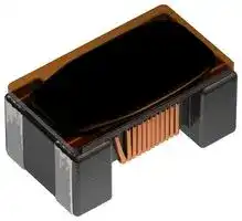
COMMON MODE FILTER, 4.8UH, 0.15A
- Manufacturer: TDK
- Product type: SMD Common Mode Chokes / Filters
- SVHC: No SVHC (04-Feb-2026)
- Impedance: 2kohm
- Inductance: 4.8µH
- Product Range: ACM Series
- Product Width: 1.2mm
- Qualification: -
- Product Height: 1.3mm
- Product Length: 2mm
- DC Current Rating: 150mA
- DC Resistance Max: 2.5ohm
- Common Mode Filter Case: 2mm x 1.2mm x 1.3mm
- Inductor Case / Package: -
- Operating Temperature Max: 85°C
- Operating Temperature Min: -40°C
| Delivery and price | |
|---|---|
| Units per pack | 2000 |
| Price | 0.165 € |
| Current stock | 1000+ |
| Lead time | 30 days |
**Common mode filters For high-speed differential signal line, general differential signal line ACM series** **==> picture [97 x 33] intentionally omitted <==** **----- Start of picture text -----**<br> Br [Cl] Pb<br>a RoHS SVHC-FreeREACH HalogenFree LeadFree<br>**----- End of picture text -----**<br> ## **ACM2012 type** ## **FEATURES** O Downsized wound type chip common mode filter that maintains required common mode filter characteristics. Impedance for common mode noise can clear 1500 [100MHz], and has excellent EMC suppression. O Differential mode impedance is suppressed, so there is virtually no affect on high speed signals. O Operating temperature range: –40 to +85°C ## **APPLICATION** Common mode noise countermeasure for high-speed differential signals where influence to the signal is a concern. USB line for PCs and peripheral devices. IEEE1394 lines and ETHERNET lines for PCs, STBs, etc. ## O LCD panel LVDS and Panel Link lines. ~~a~~ **PART NUMBER CONSTRUCTION** ## **PART NUMBER CONSTRUCTION** - - - ACM 2012 900 2P T 002 **L×W×H dimensions Impedance Series name Number of lines Packaging style Internal code 2.0×1.2×1.3 mm (** **) at 100MHz** ## ~~|~~ **CHARACTERISTICS SPECIFICATION TABLE** |**Impedance**||**DC resistance**<br>**Rated voltage**|**Rated current**|**Part No.**| |---|---|---|---|---| |**[100MHz**]||**[per 1 line]**||| |**(****)min.**|**(****)typ.**|**(****)max.**<br>**(V)max.**|**(A)max.**|| |65|90|0.19<br>50|0.4|ACM2012-900-2P-T002| |90|120|0.22<br>50|0.37|ACM2012-121-2P-T002| |150|200|0.25<br>50|0.35|ACM2012-201-2P-T002| |270|360|0.5<br>50|0.22|ACM2012-361-2P-T002| |1500|2000|2.5<br>50|0.15|ACM2012-202-2P-T002| ||Measurement equipment||| |---|---|---|---| ||Measurement item|Product No.|Manufacturer| ||Common mode impedance|4991A|Keysight Technologies| ||DC resistance|4338A|Keysight Technologies| |Insulation resistance||4339A|Keysight Technologies| * Equivalent measurement equipment may be used. ~~A~~ Please be sure to request delivery specifications that provide further details on the features and specifications of the products for proper and safe use. (1/4) Please note that the contents may change without any prior notice due to reasons such as upgrading. 20181011 cmf_commercial_signal_acm2012_en.fm ## **ACM2012 type** ## **IMPEDANCE VS. FREQUENCY CHARACTERISTICS** **==> picture [474 x 275] intentionally omitted <==** **----- Start of picture text -----**<br> 10000<br>202 Common mode 121 Common mode<br>1000<br>201 Common mode<br>361 Common mode<br>100<br>202 Differential mode<br>900 Common mode<br>10 121 Differential mode<br>201 Differential mode<br>361 Differential mode<br>— — 900 Differential mode<br>a<br>1<br>1 10 100 1000<br>Frequency (MHz)<br>Measurement equipment<br>Product No. Manufacturer<br>4991A Keysight Technologies<br>* Equivalent measurement equipment may be used.<br>)Ω<br>Impedance (<br>**----- End of picture text -----**<br> (2/4) Please be sure to request delivery specifications that provide further details on the features and specifications of the products for proper and safe use. Please note that the contents may change without any prior notice due to reasons such as upgrading. 20181011 cmf_commercial_signal_acm2012_en.fm ## **ACM2012 type** ## **SHAPE & DIMENSIONS** **==> picture [164 x 196] intentionally omitted <==** **----- Start of picture text -----**<br> 2.0±0.2<br>1 4<br>2 3<br>—<br>0.4 1.2<br>min<br>|<br>a:<br>1.2±0.2<br>1.2±0.1 0.8<br>0.5<br>0.3<br>0.05<br>**----- End of picture text -----**<br> Dimensions in mm ## **PACKAGING STYLE** ## **REEL DIMENSIONS** **==> picture [165 x 169] intentionally omitted <==** **----- Start of picture text -----**<br> s 2.0±0.5 il 2 typ.<br>1.0<br>@<br>ø13.0±0.2 9+1/–0<br>ø21.0±0.8 13±1<br>ce<br>ø180±3 I e<br>60+1/–0<br>**----- End of picture text -----**<br> Dimensions in mm **==> picture [240 x 117] intentionally omitted <==** **----- Start of picture text -----**<br> TAPE DIMENSIONS<br>0.25±0.05 Sprocketholehole 1.5 [[+0.1]] 0 2.0±0.1 4.0±0.1<br>=<br>|<br>K A 4.0±0.1<br>i Cavity<br>Dimensions in mm<br>1.75±0.1 3.5±0.1<br>B 8.0±0.2<br>**----- End of picture text -----**<br> **TAPE DIMENSIONS RECOMMENDED LAND PATTERN** 0.25±0.05 Sprocketholehole 1.5[[+0.1]] 0 2.0±0.1 4.0±0.1 ~~ee =~~ 1.1 ~~=~~ 2.6 ~~=~~ | K A 4.0±0.1 . Dimensions in mm - ~~i~~ Cavity Dimensions in mm **CIRCUIT DIAGRAM** Type A B K 1 4 ACM2012 1.4±0.1 2.25±0.1 1.4±0.1 2 3 500 to 560min. ~~== oo~~ • No polarity 160min. Taping 440min. **RECOMMENDED REFLOW PROFILE** | Preheating Soldering Natural ~~cee~~ Drawing direction cooling Peak Dimensions in mm 245°C **PACKAGE QUANTITY** 230°C 230°C Package quantity 2000 pcs/reel 180°C 5s **TEMPERATURE RANGE, INDIVIDUAL WEIGHT** 150°C **Operating Storage Individual** 60 to 120s 10 to 30s **temperature range temperature range**[] **weight** –40 to +85 °C –40 to +85 °C 10 mg The storage temperature range is for after the assembly. B ~~N —~~ Time Please be sure to request delivery specifications that provide further details on the features and specifications of the products for proper and safe use. Please note that the contents may change without any prior notice due to reasons such as upgrading. (3/4) 20181011 cmf_commercial_signal_acm2012_en.fm ## **REMINDERS FOR USING THESE PRODUCTS** Before using these products, be sure to request the delivery specifications. ## **SAFETY REMINDERS** Please pay sufficient attention to the warnings for safe designing when using this products. ## **REMINDERS** - The storage period is less than 6 months. Be sure to follow the storage conditions (temperature: 5 to 40°C, humidity: 10 to 75% RH or less). If the storage period elapses, the soldering of the terminal electrodes may deteriorate. Do not use or store in locations where there are conditions such as gas corrosion (salt, acid, alkali, etc.). - Before soldering, be sure to preheat components. - The preheating temperature should be set so that the temperature difference between the solder temperature and chip temperature does not exceed 150°C. - Soldering corrections after mounting should be within the range of the conditions determined in the specifications. If overheated, a short circuit, performance deterioration, or lifespan shortening may occur. - When embedding a printed circuit board where a chip is mounted to a set, be sure that residual stress is not given to the chip due to the overall distortion of the printed circuit board and partial distortion such as at screw tightening portions. - Self heating (temperature increase) occurs when the power is turned ON, so the tolerance should be sufficient for the set thermal design. - Carefully lay out the coil for the circuit board design of the non-magnetic shield type. A malfunction may occur due to magnetic interference. - Use a wrist band to discharge static electricity in your body through the grounding wire. - Do not expose the products to magnets or magnetic fields. - Do not use for a purpose outside of the contents regulated in the delivery specifications. - The products listed on this catalog are intended for use in general electronic equipment (AV equipment, telecommunications equipment, home appliances, amusement equipment, computer equipment, personal equipment, office equipment, measurement equipment, industrial robots) under a normal operation and use condition. The products are not designed or warranted to meet the requirements of the applications listed below, whose performance and/or quality require a more stringent level of safety or reliability, or whose failure, malfunction or trouble could cause serious damage to society, person or property. If you intend to use the products in the applications listed below or if you have special requirements exceeding the range or conditions set forth in the each catalog, please contact us. - (1) Aerospace/aviation equipment (8) Public information-processing equipment - (2) Transportation equipment (cars, electric trains, ships, etc.) - (3) Medical equipment - (9) Military equipment - (10) Electric heating apparatus, burning equipment - (4) Power-generation control equipment (11) Disaster prevention/crime prevention equipment - (5) Atomic energy-related equipment - (12) Safety equipment - (6) Seabed equipment (13) Other applications that are not considered general-purpose (7) Transportation control equipment applications When designing your equipment even for general-purpose applications, you are kindly requested to take into consideration securing protection circuit/device or providing backup circuits in your equipment. (4/4) Please be sure to request delivery specifications that provide further details on the features and specifications of the products for proper and safe use. Please note that the contents may change without any prior notice due to reasons such as upgrading. 20181011 cmf_commercial_signal_acm2012_en.fm
Updated at June 5, 2026
TDK Corporation is a globally recognized leader in electronic components and magnetic materials. Founded in 1935 to commercialize ferrites, the Tokyo-based company has evolved into a comprehensive manufacturer of high-performance passive components, sensors, and power electronics. TDK’s advanced materials technology serves as the foundation for its extensive portfolio, driving innovation across automotive, industrial, consumer electronics, and communication technologies. Our selection of TDK components heavily features their industry-leading passive components, with a primary focus on magnetics. TDK excels in manufacturing reliable inductive solutions, offering a vast array of power inductors and RF inductors optimized for demanding power management and high-frequency applications. Furthermore, their expertise in electromagnetic compatibility is showcased through a comprehensive range of EMC and RFI suppression products. This includes common mode chokes, power line filters, and specialized shielding materials designed to ensure superior signal integrity in complex designs. Beyond inductors and filtering components, TDK provides robust circuit protection and sensing solutions essential for modern engineering. The portfolio includes precision temperature sensing and compensation NTC thermistors, alongside TVS varistors and inrush current limiting components that safeguard sensitive electronics. Complemented by fixed value inductors, supercapacitors, and charging coils, TDK's versatile product offering delivers the reliability and performance required for sophisticated circuit design.
About Novapart
Novapart is a B2B electronic component broker specialising in stock shortages and cost reduction. We source hard-to-find parts and identify compliant alternatives across a catalogue of 410,000+ components from 500+ manufacturers.
Learn more →Stock Shortage Specialist
When a component is unavailable, discontinued or has an unacceptable lead time, we tap into our network of vetted European and Asian distributors to source what you need — without compromising on quality or traceability.
Request a quote →Compliant Alternatives
We identify pin-to-pin, electrically equivalent substitutes that meet the same certifications (RoHS, AEC-Q100, REACH) as your original specification — validated against datasheets, not just part numbers. Often at a lower cost.
BOM Analysis service →