
Image not available
Illustrative purposes only

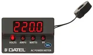
ACM20-4-AC1-R-C
POWER METER
⚠️ Reference pricing provided. In case of supply shortages, we will connect you with our trusted procurement partners to ensure your project's continuity.
- Manufacturer: DATEL
- Product type: Digital Panel Meters
- Meter Range: 0A to 32A / 85V to 264V / 0W to 9999W / 1 (Power Factor)
- Digit Height: 9.14mm
- Product Range: ACM20 Series
- Meter Function: AC Current / AC Voltage / Power / Power Factor
- Panel Cutout Width: 36.22mm
- Supply Voltage Max: 264VAC
- Supply Voltage Min: 85VAC
- Panel Cutout Height: 22.1mm
- No. of Digits / Alpha: 4
- Operating Temperature Max: 60°C
- Operating Temperature Min: 0°C
| Delivery and price | |
|---|---|
| Units per pack | 100 |
| Price | 55.31 € |
| Current stock | 10+ |
| Lead time | 30 days |
Datasheet

## **www.murata-ps.com** ## **ACM20 Series** Four-Function AC Power Meters **==> picture [67 x 122] intentionally omitted <==** **----- Start of picture text -----**<br> | ;<br>New!<br>Low-Wattage<br>Models<br>Available<br>**----- End of picture text -----**<br> **==> picture [153 x 17] intentionally omitted <==** **----- Start of picture text -----**<br> Actual size C AY ® US E156931<br>**----- End of picture text -----**<br> ## **FEATURES** - Displays AC Volts, Amps, Watts, and Power Factor or Hertz - Two display modes: continuous auto cycling or fi xed - Universal 85-264Vac (47-63Hz) operating range (Measurement Category II) - Built-in current transformers simplify installation; choice of 10A, 32A, or 100A ranges - Ideal for power distribution units (PDUs) and power strips - True-rms readings of complex voltage and current waveforms - Low-power consumption: less than ¼watt from 120Vac - One-piece polycarbonate housing fi ts ‘0U’ & ‘1U’ racks - Surface mount design occupies minimal panel space - Bright red LED-display with four annunciators - Optional Frequency reading models (0.1Hz resolution) Approvals to UL/CSA/IEC/EN 61010-1 ## **PRODUCT OVERVIEW** Murata Power Solutions’ ACM20 series AC power meters display the most critical measure- ~~a~~ ments in mains-powered equipment: voltage, amperage, active power (watts), and power factor. A front panel selector-switch provides two modes of operation: a fi xed reading of any of the four parameters, or a continuous cycling through all four measurements. An optional model displays line frequency with 0.1Hz resolution. All ACM20 multi-function power meters include built-in current transformers—no other user-supplied components are required. ACM20 series AC power meters are available in a choice of three input ranges: 0-10A (with 0.001A resolution, 999.9 watts max.); 0-32A (with 0.01A resolution, 9999 watts max.); and 0-100A (0.1A resolution, 26.4kW max.). An 85-264Vac (47-63Hz) operating supply range makes these power meters perfect for worldwide power monitoring applications. And, unlike conventional, average-responding products, ACM20 power meters can accurately display the real power and true-rms current values of triangle waves, square waves, and other irregularly shaped waveforms, with a typical accuracy of ±1% of full scale. Their large (0.36"/9.2mm), bright red LED display makes ACM20 AC power meters easily readable from as far as 15 feet (5 meters). All units are packaged in a one-piece, vibration resistant, polycarbonate housing that can be installed in vertical ‘0U’ and ‘1U’ rack spaces. Their miniature size is perfect for UPS power sources, power strips, laboratory instrumentation, alternative energy applications, and any other products that require precise monitoring of AC power. ## ~~ee~~ **SIMPLIFIED SCHEMATIC DIAGRAM** **==> picture [444 x 197] intentionally omitted <==** **----- Start of picture text -----**<br> VOLTS AMPS WATTS PF<br>LOAD CURRENT hd<br>+5V<br>L1<br>A/D<br>CONVERTER<br>+5V<br>CURRENT B<br>LIMITED ala +5V<br>85-264 Vac A AC/DC MICRO-<br>47-63 Hz CONVERTER CONTROLLER<br>SUPPLY<br>L& Be<br>For full details go to<br>www.murata-ps.com/rohs SEL<br>ts Y ’ } CD<br>**----- End of picture text -----**<br> ~~SEE~~ **www.murata-ps.com/support** ~~SEE~~ **MPM_ACM20 Series.B04** Page 1 of 6 ## **ACM20 Series** Four-Function AC Power Meters ## **Performance/Functional Specifi cations** Typical at TA=+ 25ºC, 120Vac @ 60Hz, unless otherwise noted **==> picture [244 x 555] intentionally omitted <==** **----- Start of picture text -----**<br> Measurement Limits Min. Typ. Max. Units<br>AC Voltage 85.0 - 264.0 Volts<br>AC Current, 10A models ➀ 0.00 - 9.999 Amperes<br>AC Current, 32A models ➀ 0.00 - 32.00 Amperes<br>AC Current, 100A models ➀ 0.0 - 100.0 Amperes<br>Active Power: 10A models 0 - 999.9 Watts<br>Active Power: 32A models 0 - 9999 Watts<br>Active Power: 100A models 0 - 26.4 kW<br>Frequency 47.0 - 63.0 Hz<br>Power Factor .00 1.00 - -<br>Overcurrent Rating ➁ 1.5 x rated full-scale current<br>Performance<br>Sampling Rate 2-3 samples / sec<br>Voltage Accuracy ➂ ±1%<br>Current Accuracy ➂ ±1%<br>Power Accuracy ➂ ±2%<br>Frequency Accuracy ➂ ±0.1 Hz<br>Power Factor Accuracy ±3%<br>Measurement Bandwidth 140Hz (Voltage), 14kHz (Current)<br>Temperature Drift (0 to 60ºC) 0.5 Counts/ºC<br>Zero-Current Reading (within 2 sec.) 0.00 Amps<br>Zero-Power Reading (within 2 sec.) 0 Watts<br>UL/IEC61010-1 Measurement category II<br>Supply Voltage (TB1) (Measurement Category II)<br>All Models – 47-63 Hz 85 120 264 Vac<br>Supply Current ➃<br>All Models 35 50 110 mA<br>Power Supply Terminal Block<br>Wire Size 16-22AWG, solid or stranded<br>Insulation Strip Length 6.4mm (0.250 in)<br>Screw Tightening Torque 0.4Nm (3.6 lb-in)<br>Rated Voltage 300Vac<br>Display<br>Display Type and Size 4 Digit LED, 9.14mm (0.36in) high<br>Overrange Indication Flashing ‘9999’ Watts ➄<br>Decimal Point Selection Automatically Set<br>Physical/Environmental<br>Operating Temperature 0 – +60 °C<br>Storage Temperature –40 – +75 °C<br>Humidity (non-condensing) 0 – 85 %<br>Dimensions See mechanical specifi cations<br>Weight: 32A models 1.3oz (37.9g)<br>Weight: 100A models 1.5oz (43.5g)<br>Hex Nut Tightening Torque 0.14 N-m (20 ozf-in)<br>**----- End of picture text -----**<br> - ➀ Specifi ed full-scale currents are those passing through the power meter’s built-in current transformer’s primary load-circuit. - ➁ The overcurrent rating of 1.5 x the rated full-scale current is a continuous rating and applies to the current passing through the built in current transformer. Accuracy is guaranteed up to the rated current. - ➂ ACM20 Power Meters are calibrated with near full-scale 60Hz sine-wave inputs. - ! ## **ORDERING INFORMATION** **ACM20-2-AC1-R-C** 10A, 85-264Vac Supply (Power Factor Reading) **ACM20-5-AC1-R-C** 32A, 85-264Vac Supply (Power Factor Reading) **ACM20-4-AC1-R-C** 100A, 85-264Vac Supply (Power Factor Reading) **ACM20-2-AC1-R-F-C** 10A, 85-264Vac Supply (Frequency Reading) **ACM20-5-AC1-R-F-C** 32A, 85-264Vac Supply (Frequency Reading) **ACM20-4-AC1-R-F-C** 100A, 85-264Vac Supply (Frequency Reading) ## **TECHNICAL NOTES** - **IMPORTANT!** To ensure safe and reliable operation, ACM20 power meters must be installed and serviced by qualifi ed technical personnel. Contact Murata Power Solutions if there is any doubt regarding their installation or operation. **1. Measurement Type:** ACM20 series multifunction AC power meters employ a precision energy metering integrated circuit and a lowpower microcontroller to measure and display the rms voltage and current, active (real) power, power factor (or line frequency on ‘–F’ suffi x models) of ac mains supplies from 47-63Hz. Please note, ACM20 power meters use the voltage present at their TB1 terminal block and the secondary current of their built-in current transformer L1 to calculate and then display VOLTS, AMPS, WATTS, power factor (PF), or line frequency on ‘-F’ HERTZ models. While the ACM20 displays the rms value of line voltage and line current, the VOLTS reading has an upper limit of 140Hz (-3db point), which means rectangular-shaped voltage waveforms, and waveforms with sharp transitions, will read lower than their true-rms value. For example, a square wave line voltage will read approximately 1-2% lower, a triangle wave will read 3% lower, and a modifi ed sine wave will read 18% lower. The oscillograms on page seven illustrate typical ACM20 VOLTS readings when powered from four ac waveforms. The 140Hz bandwidth limit does not apply to the WATTS reading nor to the AMPS reading. The circuitry used for these two measurements has an upper bandwidth of 14kHz. ACM20 power meters are mains operated devices designed to measure ac currents and voltages, within the specifi ed limits previously noted. DC currents and voltages will not be measured accurately. **2. Basic Operation** : Upon application of ac power to TB1, the unit will fi rst perform a self-test routine and then continuously display ac volts with the VOLTS LED annunciator illuminated. The display will remain in the VOLTS mode as long as the front panel ‘SEL’ button is not touched. After the unit powers up to normal operation in the VOLTS reading mode, momentarily (approximately one second) touching the ‘SEL’ button on the unit’s front panel three times in succession will cycle the display to AMPS, WATTS, and end at PF (or HERTZ for ‘–F’ models). Momentarily touching ‘SEL’ a fourth time will return the display back to the VOLTS reading mode. Holding the ‘SEL’ button down for 3 seconds will place the unit in a continuous auto-cycling mode, and the display will repetitively scroll through all four measurements, with each measurement remaining displayed for 3 seconds. - ➃ All specifi ed maximum supply currents are steady state; larger surge currents can occur at initial application of line power. - ➄ Applies to 10A and 32A models only. **www.murata-ps.com/support** **MPM_ACM20 Series.B04** Page 2 of 6 **ACM20 Series** Four-Function AC Power Meters When the continuous auto-cycling mode is initially selected, the unit will briefl y display ‘Auto On’ before continuous cycling begins. Momentarily touching the ‘SEL’ button again will cause the unit to briefl y display ‘Auto OFF’ before it returns to the fi xed VOLTS reading mode. **Displaying a specifi c mode on power up:** Units manufactured after February 2012 can be confi gured to automatically show any one of the four display modes upon future applications of ac power. For example, it may be desirable to confi gure the unit to always power up in the AMPS mode. To set the unit to always read AMPS on power up, tap the SEL switch until the AMPS mode is displayed, and then leave the unit in this mode for at least 60 seconds. As long as the SEL switch is not pressed again during the 60 second interval, the unit will confi gure itself to always power up displaying the chosen mode, which is AMPS in this example. In summary, operating the unit undisturbed in a particular display mode for 60 seconds or longer will automatically confi gure the unit to display that particular mode the next time ac power to the unit is cycled off and back on. This functionality also applies to the autocycle mode, that is, the unit can be confi gured to always power up in the auto-cycle (scrolling) display mode by following the instructions outlined above. **3. Calibration:** Due their digital design, ACM20 power meters cannot be calibrated in the fi eld. ACM20 power meters are factory-calibrated to meet their specifi ed accuracies with the supplied L1 current transformer. Use of any other current transformer will produce signifi cant errors for the Amps, Watts, and Power Factor measurements. - Contact Murata Power Solutions if additional information is required regarding calibration, setup, or any other technical issue pertaining to ACM20 power meters. **4. Wiring:** All power supply wiring must be rated for the voltages and currents they will carry and must comply with any code or applicationmandated requirements pertaining to the user’s specifi c installation. **5. Supply Fusing, and Grounding:** Wires specifi ed in the Functional Specifi cations section must be used for making connections to ACM20 series power meters. No connection is required for earth/ chassis ground. ACM20 series power meters are not internally fused. Terminal block TB1 is to be used only for powering the power meter's internal circuitry; it must not be used to supply power to external loads. The supply wires feeding these power meters must be fused with a 0.5A/250V time delay/time lag fuse, in accordance with applicable regulatory codes. Wire insulation must be stripped to within ±10% of the stated dimensions, and wires should be inserted into TB1 such that their insulation is not pinched by the screw terminal. **6. Current Transformer Polarity:** In order to perform accurate Watts and Power Factor measurements, connections to the two rear power supply inputs, TB1-A and TB1-B, and built-in current transformer L1 must have the proper polarity. That is, the load current fl owing in the wire passing through L1's center hole must have the same polarity as the line voltage connected to TB1-A and TB1-B. The wiring diagrams in Figures 1-4 ensure that, for a purely resistive load, current fl owing in current transformer L1’s primary circuit will have the same polarity as the applied voltage at TB1. If proper polarity is not followed, the Watts and Power Factor readings will be zero. To correct a zero Watts reading, simply reverse the direction of the load wire passing through the hole in L1. **7. Connector Torque Ratings: I** t is important to tighten TB1’s, screwterminals to their rated torque specifi cation of 3.6 pound-inches (0.4Nm). Proper tightening will minimize connector losses and ensure safe, reliable operation. **8. Isolation:** Except for the 2-56 thread metallic mounting studs, all of the ACM20 power meter’s internal components (printed circuit board, resistor, capacitors, current transformer L1’s secondary leads, etc.) are at the ac-mains potential connected to TB1. ACM20 power meters are designed to measure and be powered from one ac power-source only. Any other connection schemes will introduce signifi cant measurement errors. ## **TYPICAL WIRING DIAGRAMS** **==> picture [350 x 190] intentionally omitted <==** **----- Start of picture text -----**<br> 120 V<br>LOAD<br>|<br>Epoxy encapsulation<br>8<br>B TB1<br>Fuse*<br>A<br>|<br>ie; Ml<br>7<br>Polarity dot on bottom<br>H N<br>120 Vac (50/60 Hz)<br>**----- End of picture text -----**<br> Note: If the ACM20 displays zero Watts with power applied to the load, reverse the direction of the wire passing through the CT's center hole. See Technical Note 6 for more information. **Figure 1. Wiring diagram for 110/120V single phase systems** ***See technical note 5.** ~~—______~~ **www.murata-ps.com/support** **MPM_ACM20 Series.B04** Page 3 of 6 **ACM20 Series** Four-Function AC Power Meters ## **TYPICAL WIRING DIAGRAMS, CONT.** **==> picture [513 x 397] intentionally omitted <==** **----- Start of picture text -----**<br> 220 V<br>LOAD<br>b<br>Epoxy encapsulation<br>Note: If the ACM20 displays zero Watts with B TB1<br>power applied to the load, reverse the direction Fuse*<br>A<br>of the wire passing through the CT's center hole. See Technical Note 6 for more information. 7<br>Aes : © :<br>7<br>Polarity dot on bottom O O<br>L1 L2<br>220 Vac (50/60 Hz)<br>Figure 2. Wiring diagram for 220/240V systems with no neutral *See technical note 5.<br>120 V<br>LOAD<br>Epoxy encapsulation<br>Note: If the ACM20 displays zero Watts with B TB1<br>power applied to the load, reverse the direction Fuse*<br>A<br>of the wire passing through the CT's center hole.<br>See Technical Note 6 for more information.<br>§ :<br>4— =<br>Polarity dot on bottom<br>1,<br>L1 Neutral L2<br>220 Vac (50/60 Hz)<br>**----- End of picture text -----**<br> **Figure 3. Wiring diagram for 120/240V systems with neutral (monitoring L1)** ***See technical note 5.** **==> picture [513 x 181] intentionally omitted <==** **----- Start of picture text -----**<br> 120 V<br>LOAD<br>Epoxy encapsulation<br>on °<br>Note: If the ACM20 displays zero Watts with B TB1<br>power applied to the load, reverse the direction Fuse*<br>A<br>of the wire passing through the CT's center hole.<br>See Technical Note 6 for more information.<br>4 ye i<br>Polarity dot on bottom<br>we<br>L1 Neutral L2<br>220 Vac (50/60 Hz) *See technical note 5.<br>**----- End of picture text -----**<br> **Figure 4. Wiring diagram for 120/240V systems with neutral (monitoring L2)** ~~EE~~ **www.murata-ps.com/support** **MPM_ACM20 Series.B04** Page 4 of 6 ## **ACM20 Series** ## Four-Function AC Power Meters ## **PANEL INSTALLATION** Using Figure 5 as a guide, carefully insert the ACM20 assembly into the panel opening. From the rear of the panel, install and then tighten the four #2-56 hex nuts over the threaded studs. **Tighten each nut to 15 to 20 ozf-in (0.106 to 0.140 N-m).** Use only the factory-supplied hardware as the use of substitute hardware could result in an unsafe installation and/or adversely affect the reliability of the installation. All connections to ACM20 power meters must be made after the unit is securely attached to the panel and with all associated load and supply voltages de energized (off), using extreme caution and observing all safety measures applicable to the user’s installation. **==> picture [534 x 328] intentionally omitted <==** **----- Start of picture text -----**<br> Care should be exercised when passing conductors through the<br>The recommended range of panel thickness that can be used with the<br>power meter’s built-in current transformer L1. The installed wire-<br>supplied hardware is 0.040 inches (1.0mm) to 0.25 inches (6.4mm).<br>positions should be such that minimal mechanical forces are applied<br>Panel thicknesses outside of this range may require additional user-<br>to current transformer L1, TB1, or to the ACM20 power meter itself.<br>supplied hardware or modifi cations. Front panel space permitting,<br>In high-vibration environments, it is strongly recommended that<br>ACM20 power meters will fi t most existing ACA-20RM / ACA-20PC<br>adequate strain reliefs be used for all wiring.<br>ammeter cutouts, allowing for easy upgrading of existing installations.<br>PANEL<br>PANEL CUTOUT<br>RECOMMENDED DRILL AND PANEL CUTOUT DIMENSIONS<br>2-56 Hex Nuts (4 places)<br>ACM20<br>Tighten each nut to INTERNAL CORNER RADII:<br>_} | 15 to 20 ozf-in (0.106 to 0.140 N-m). 0.032 (0.81) MAX.<br>L1 1.07 0.838* - 0.870<br>(27.18) (21.29* - 22.10)<br>= me<br>1.336* - 1.426<br>(33.93* - 36.22)<br>1.626 (41.30)<br>SIDE VIEW<br>0.093 (2.362) DIAMETER (4 REQUIRED)<br>Figure 5. Panel Installation<br>Panel Cutout<br>**----- End of picture text -----**<br> The recommended range of panel thickness that can be used with the supplied hardware is 0.040 inches (1.0mm) to 0.25 inches (6.4mm). Panel thicknesses outside of this range may require additional usersupplied hardware or modifi cations. Front panel space permitting, ACM20 power meters will fi t most existing ACA-20RM / ACA-20PC ammeter cutouts, allowing for easy upgrading of existing installations. * The two dimensions marked with an * specify the minimum recommended panel cutout opening for ACM20 power meters. Space permitting, the larger dimensions noted (0.87in., and 1.426in.) should be used. The panel opening must be centered vertically and horizontally between the four 0.093 (2.362mm) diameter holes. ## **1. Description of safety marks:** Caution, risk of electrical shock Caution, risk of danger Equipment is protected throughout by double or reinforced insulation ## **2. Cleaning Instructions: Gently clean with dry cloth only.** **3. Caution: if the equipment is used in a manner not specifi ed by Murata Power Solutions, the protection provided by the equipment may be impaired.** **www.murata-ps.com/support** **MPM_ACM20 Series.B04** Page 5 of 6 **ACM20 Series** ## Four-Function AC Power Meters ## **MECHANICAL SPECIFICATIONS** **==> picture [498 x 261] intentionally omitted <==** **----- Start of picture text -----**<br> 2.10 (53.3) Dimensions are in inches (mm). (12.95)0.51<br>0.12 (3.05) (min)<br>Tolerances (unless otherwise specified):<br>.XX ± 0.02 (0.51)<br>.XXX ± 0.010 (0.254) Fo<br>| AONE h<br>Angles ± 2˚<br>1.43<br>(36.3) Components are shown for reference only. (27.20)1.07 Side View<br>VOLTS AMPS WATTS PF<br>q on ,<br>SEL<br>AC POWER METER<br>0.40 0.12 (3.05) (min)<br>Front View (10.16)<br>nm<br>Lead Length e<br>2.0 (50.5) min.<br>B TB1<br>=<br>0.60 0.086 DIA (REF) L1 A<br>(15.24) 2-56 UNC THREAD<br>(max)<br>0.22 (5.59) 0.33 (8.39)<br>(min) 1.63 (min)<br>2— = ~ L<br>(41.4)<br>Di ameter:<br>Bottom View 10A and 32A models: 0.35 (8.9) Back View<br>**----- End of picture text -----**<br> Di **ameter:** 10A and 32A models: 0.35 (8.9) 100A models: 0.57 (14.5) ## **OSCILLOGRAMS** **The graphs below show typical ACM20 power meter VOLTS readings when the unit is powered from four common ac-voltage waveforms.** Murata Power Solutions, Inc. 11 Cabot Boulevard, Mansfi eld, MA 02048-1151 U.S.A. ISO 9001 and 14001 REGISTERED Murata Power Solutions, Inc. makes no representation that the use of its products in the circuits described herein, or the use of other technical information contained herein, will not infringe upon existing or future patent rights. The descriptions contained herein do not imply the granting of licenses to make, use, or sell equipment constructed in accordance therewith. Specifi cations are subject to change without notice. _**© 2014 Murata Power Solutions, Inc.**_ **www.murata-ps.com/support** **MPM_ACM20 Series.B04** Page 6 of 6
Updated at February 9, 2023
About Novapart
Novapart is a B2B electronic component broker specialising in stock shortages and cost reduction. We source hard-to-find parts and identify compliant alternatives across a catalogue of 410,000+ components from 500+ manufacturers.
Learn more →Stock Shortage Specialist
When a component is unavailable, discontinued or has an unacceptable lead time, we tap into our network of vetted European and Asian distributors to source what you need — without compromising on quality or traceability.
Request a quote →Compliant Alternatives
We identify pin-to-pin, electrically equivalent substitutes that meet the same certifications (RoHS, AEC-Q100, REACH) as your original specification — validated against datasheets, not just part numbers. Often at a lower cost.
BOM Analysis service →