
Image not available
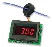
Illustrative purposes only

ACA-20RM-4-AC4-RL-C
Digital Panel Meter, LED, 3-1/2 Digits, AC Current, 0A to 50A
⚠️ Reference pricing provided. In case of supply shortages, we will connect you with our trusted procurement partners to ensure your project's continuity.
- Manufacturer: MURATA POWER SOLUTIONS
- Product type: Digital Panel Meters
- No. of Digits / Alpha:3-1/2; Meter Function:AC Current; Meter Range:0A to 50A; Digit Height:9.4mm; Panel Cutout Height:21.29mm; Panel Cutout Width:33.93mm; Supply Voltage Min:170VAC; Supply
- SVHC: Lead (17-Jan-2022)
- Meter Range: 0A to 50A
- Digit Height: 9.4mm
- Product Range: -
- Meter Function: AC Current
- Panel Cutout Width: 33.93mm
- Supply Voltage Max: 264VAC
- Supply Voltage Min: 170VAC
- Panel Cutout Height: 21.29mm
- No. of Digits / Alpha: 3-1/2
- Operating Temperature Max: 60°C
- Operating Temperature Min: 0°C
| Delivery and price | |
|---|---|
| Units per pack | 1 |
| Price | 87.03 € |
| Current stock | 200+ |
| Lead time | 30 days |
Datasheet

## **- ACA 20RM Series**
## **www.murata-ps.com**
- True-RMS-AC Ammeters with Built-in CT
- **C® US E156931**
- Murata Power Solutions = **FEATURES** Murata Power Solutions’ new ACA-20RM Series are the world’s fi rst digital ac-ammeters to incorporate a built-in current transformer (CT) to directly measure the true-rms value of Built-in CTs provide true-rms values of complex waveforms complex, non-sinusoidal ac currents from 2 to 50A – no bulky and expensive 5A “donut”
Murata Power Solutions’ new ACA-20RM Series are the world’s fi rst digital ac-ammeters to incorporate a built-in current transformer (CT) to directly measure the true-rms value of complex, non-sinusoidal ac currents from 2 to 50A – no bulky and expensive 5A “donut” CTs are required! Operation and setup is straightforward: simply pass the load-carrying wire through the on-board CT, apply power, and the ammeter is fully operational.
- Perfect for measuring AC current in IT applications
- Five ranges measure: 0-0.2A, 0-2A, 0-20A, 0-30A and 0-50A
Five input ranges measure 0-0.2 amps (0.1mA resolution), 0-2 amps (0.001A resolution), 0-20 amps (0.01A resolution), 0-30 amps (0.1A resolution) or 0-50 amps (0.1A resolution). The 50A model features an oversized split-core current transformer that easily accommodates wires sizes up to 4 AWG (21.2mm[2] ). Two power supply options are available: 85-140V (47-63Hz), and 170-264V (47-63Hz).
- 50A models features a split-core CT for easy installation
- Self-powered from 85-140Vac or 170-264Vac
- Large, easy-to-read, red LED display with 0.37" digits
All models are totally self-contained; no external components are required. Power consumption from a nominal 120V or 220V ac supply is less than 50mA. And, precision autozeroing circuitry, super-stable components, and an rms-to-dc converter circuit combine to achieve excellent performance when measuring the complex, non-sinusoidal, ac currents found in today’s computer/telecom equipment.
- Reliable single-board construction
- Digital replacement for analog meters
- Approvals to UL/cUL/IEC/61010-1
ACA-20RM Series ammeters feature full-size, 0.37" (9.4mm) high, 3½ digit, bright red LED-displays and a built-in bezel/fi lter assembly that features metal fasteners. They are panel-cutout compatible with MPS’s DMS-20 Series of ac voltage and frequency monitors, making ACA-20RM ammeters perfect replacements for older, less reliable, analog panel meters in today’s sophisticated IT instrumentation.
**==> picture [113 x 91] intentionally omitted <==**
**----- Start of picture text -----**<br>
For full details go to<br>gig www.murata-ps.com/rohs [©]<br>**----- End of picture text -----**<br>
**==> picture [314 x 238] intentionally omitted <==**
**----- Start of picture text -----**<br>
CAL.<br>+<br> 3½ DIGIT<br>A/D CONVERTER<br>–<br>+V –V LED DISPLAY<br>RMS-to-DC<br>CONVERTER<br>POWER<br>CONVERTER<br>(L1)<br>BUILT-IN<br>CURRENT A B<br>TRANSFORMER<br>TB1<br>Yo<br>© MEASURED AC E<br>CURRENT LIMITED<br>LOAD CURRENT<br>AC SUPPLY<br>**----- End of picture text -----**<br>
**www.murata-ps.com/support**
**MPM_ACA-20RM.C01** Page 1 of 5
## **- ACA 20RM Series**
## True-RMS-AC Ammeters with Built-in CT
## **Performance/Functional Specifi cations**
Typical at TA = +25°C, unless otherwise noted.
**==> picture [241 x 567] intentionally omitted <==**
**----- Start of picture text -----**<br>
Rated Full-Scale Current ➀ Min. Typ. Max. Units<br>ACA-20RM-O-ACX-RL – – 199.9 mA<br>ACA-20RM-1-ACX-RL – – 1.999 A<br>ACA-20RM-2-ACX-RL – – 19.99 A<br>ACA-20RM-4-ACX-RL – – 50.0 A<br>ACA-20RM-5-ACX-RL – – 30.0 A<br>Overcurrent Rating ➁ 1.5 x Rated Full-Scale Current<br>Performance<br>Sampling Rate 2.5 Samples per second<br>Accuracy ➂ ±0.4%FS ±3 Counts with 60Hz<br>Sine-Wave Input<br>Measurement Type RMS Responding, Crest Factors of 1-5<br>Temperature Drift (0 to 60 °C) – ±0.2 ±0.4 Cnts/°C<br>Zero-Current Reading (within –001 000 001 Cnts<br>30 sec.)<br>Dielectric Withstanding Voltage 2000 – – Vdc<br>UL/IEC61010-1 Measurement category II<br>Power Supply Voltage<br>ACA-20RM-X-AC3-RL 85 120 140 Vac/47-63Hz<br>ACA-20RM-X-AC4-RL 170 220 264 Vac/47-63Hz<br>Power Supply Current ➃<br>ACA-20RM-X-AC3-XX – 30 50 mA/47-63Hz<br>ACA-20RM-X-AC4-XX – 30 50 mA/47-63Hz<br>Power Supply Terminal Block<br>Wire Size 16-22AWG, Solid and stranded<br>Insulation Strip Length 0.250 inches<br>Screw Tightening Torque 2.2 lb·in (0.25 N·m) ±20%<br>Rated Voltage 310Vac<br>Display<br>Display Type and Size 3½ Digit Red LED, 0.37"/9.4mm High<br>Overrange Indication “1___”<br>Decimal Point Fixed, model dependent<br>(see full-scale input Current)<br>Physical/Environmental<br>Operating Temperature 0 – +60 °C<br>Storage Temperature –40 – +75 °C<br>Humidity –40 – +95 %<br>Dimensions (non-condensing) Model dependent, see page 3 & 4<br>Weight<br>ACA-20RM-0,1,2-XXX-XX 1.1 ounces (31 grams) nominal<br>ACA-20RM-4-XXX-XX 2.1 ounces (60 grams) nominal<br>ACA-20RM-5-XXX-XX 1.5 ounces (43 grams) nominal<br>**----- End of picture text -----**<br>
- ➀ Specifi ed full-scale currents are those passing through the ammeter’s built-in current transformer’s primary load-circuit. See Notes 2 and 3 below for additional model-specifi c information.
- ➁ The overcurrent rating of 1.5 x the rated full-scale current is a continuous rating and applies to the current passing through the built in current transformer only, it does not apply to any external circuit-wiring or external loads. Accuracy is guaranteed up to the rated current level.
- ➂ Specifi ed accuracy applies to inputs with crest factors (CF) up to 2.0, where CF = Vpeak/Vrms. Crest factors of 2 to 5 introduce an additional error of ±3% of full scale. Ammeters are calibrated with a near full-scale 60Hz sine-wave current fl owing through the ammeter’s built-in CT.
- ➃ All specifi ed maximum power supply currents are steady state; larger surge currents can occur at initial application of line power.
## ~~**Ordering Information**~~
## **ACA-20RM- 1 - AC3 - R L - C**
Add -C for RoHS **LED Color: RL** = Low-Power Red **Input Range: Power: 0** = 199.9mA **AC3** = 85-140Vac@50/60Hz **1** = 1.999A **AC4** = 170-264Vac@50/60Hz
- **2** = 19.99A
- **4** = 50.0A (with split-core fl ying-lead CT)
- **5** = 30.0A (with fl ying-lead CT)
**Accessories: DMS-20-CP** Panel Cutout Punch
**See www.murata-ps.com/dpm-availability for model-specifi c availability.**
## **TECHNICAL NOTES**
- **IMPORTANT!** To ensure safe and reliable operation, ACA-20RM ammeters must be installed and serviced by qualifi ed technical personnel after reading this data sheet in it's entirety. Contact Murata Power Solutions if there is any doubt regarding their installation or operation.
**1. Measurement Type** : ACA-20RM ac ammeters employ true-rms input circuitry to measure the stepped-down output of their on-board current transformers (CT). Stated accuracy is measured using a sinewave input at, or close to, the specifi ed full scale input, at a nominal line frequency of 60HZ.
**2. Calibration** : Periodic recalibration of ACA-20RM ammeters is not required under normal indoor environments. If user calibration is deemed necessary, it must be performed by qualifi ed technical personnel since potentially lethal voltages and currents are applied to the ACA-20RM during the calibration process.
Calibration is performed with approximately 95% of the specifi ed full-scale current fl owing through the ammeter’s built-in CT. A fully insulated, non-metallic adjusting tool must be used to adjust the calibration potentiometer, located on the back of the ammeter (see Mechanical Specifi cations section).
**www.murata-ps.com/support**
**MPM_ACA-20RM.C01** Page 2 of 5
## **- ACA 20RM Series**
True-RMS-AC Ammeters with Built-in CT
The calibration potentiometer has approximately ¾ of a turn of rotation; do not force its adjustment screw past the end stops. Contact MPS if additional information is required regarding calibration, setup, or any other technical issue pertaining to ACA-20RM ac ammeters.
**3. Wire Gauges and Fusing** : Wires specifi ed in the Functional Specifi - cations section must be used for making connections to ACA-20RM series ammeters. All power-supply and load wiring must be rated for the supply voltages and currents they will conduct and must comply with any code or application-mandated requirements pertaining to the user’s specifi c installation.
- ACA-20RM ammeters are not internally fused. Terminal block TB1 is to be used only for powering the ammeter’s internal circuitry; it must not be used to supply power to external loads. The supply wires feeding these ammeters must be fused with a 0.25A/250V time delay/time lag fuse, in accordance with applicable regulatory codes.
Wire insulation must be stripped to within ±10% of the stated dimensions, and wires should be inserted into TB1 such that their insulation is not pinched by the screw terminal.
**5. Connector Torque Ratings** : Be sure to tighten TB1’s screw-terminals to 3.6 pound-inches (0.4Nm). Proper tightening will ensure reliable long-term operation.
**6. Isolation** : The on-board CT (L1) provides a minimum of 2000Vdc isolation between the current-carrying load conductor passing through its opening and the ammeter’s power source that’s connected to TB1. Of course, this isolation rating applies only to applications where the load wire does not connect directly or indirectly to TB1-A or TB1-B (i.e., where two different ac supplies are involved).
**7. Split-Core CT (Clamp-on) Models** : 50A models feature a split-core current transformer that can be clamped around a current-carrying load conductor without having to disconnect or remove power from the load’s power source. This live-connection capability can only be used if the load’s power source is isolated (see technical note 6) from the ammeter’s own power source that’s connected to TB1. The ammeter’s ac power supply must always be denergized before making connections to TB1. Refer to the ‘Panel Installation’ section of this data sheet for additional information.
**4. AC Supply Polarity and Grounding** : The two supply inputs, TB1 ‘A’ and ‘B’, on ACA-20RM ammeters are not polarity sensitive, that is, they have no ‘AC LO’ or ‘AC HI’ designations. Also, ac-powered ACA-20RM ammeters do not include or require a connection to earth/chassis ground.
## **WIRING DIAGRAMS**
First pass and carefully dress one external load wire through L1, then connect the AC supply and load wires to TB1 as shown. Ensure all wires are stripped and properly tightened. For accurate operation, make only
**==> picture [188 x 183] intentionally omitted <==**
**----- Start of picture text -----**<br>
BACK VIEW<br>A<br>FUSED AC POWER e TB1 e@<br>B €| eeececececcceceaa \ |<br>| *~ ie<br>oO D0<br>TO AC LOAD = OO000 C e<br>L1<br>U FROM AC SUPPLY<br>Figure 2. Connections for pc-board mounted CT's<br>ot.<br>**----- End of picture text -----**<br>
one pass with load wire through the on-board CT (only one primary turn). For split-core CT models, make sure to fully engage the CT's Locking mechanism
**==> picture [152 x 128] intentionally omitted <==**
**----- Start of picture text -----**<br>
BACK VIEW<br>e<br>A<br>FUSED AC POWER TB1<br>B 2 | e@eceeecccececee<br>8 ; a ad<br>'<br>e@eceeeccecececee<br>e oo e<br>L1<br>TO AC LOAD<br>**----- End of picture text -----**<br>
**==> picture [51 x 5] intentionally omitted <==**
**----- Start of picture text -----**<br>
FROM AC SUPPLY<br>**----- End of picture text -----**<br>
**Figure 3.** Connection for fl ying lead CT's
**www.murata-ps.com/support**
**MPM_ACA-20RM.C01** Page 3 of 5
## **- ACA 20RM Series**
True-RMS-AC Ammeters with Built-in CT
## **PANEL INSTALLATIONS**
All connections to ACA-20RM Series ammeters must be made after the ammeter is securely attached to its panel and with all associated load and supply voltages de-energized (off). However, using extreme caution and observing all safety measures applicable to the user’s installation, 50A split-core CT models can be connected to energized current-carrying load conductors, but connections to TB1 must always be made with the ammeter’s power source off.
Care should be exercised when passing the load-carrying conductor through the meter’s built-in CT—particularly when larger conductors are used. The installed wire-positions should be such that minimal mechanical forces are applied to the built-in CT, TB1, or to the ammeter itself. In high-vibration environments, it is strongly recommended that adequate strain reliefs be used for all load and supply wiring.
Using Figure 4 as a guide, carefully insert the bezel/color fi lter assembly into the panel opening. From the rear of the panel, install the four round plastic standoffs over the bezel’s threaded studs. Install the pc-board assembly; then attach and securely tighten each of the four hex nuts to 15-20 ozf-in (0.106 to 0.140 N-m). Use only the factory-supplied hardware as the use of substitute hardware could result in an unsafe installation and/or adversely affect the reliability of the ammeter itself.
The recommended range of panel thickness that can be used with the supplied hardware is 0.040 inches (1.0mm) to 0.125 inches (3.2mm). Panel thickness outside of this range will require additional user-supplied hardware and/or modifi cations.
**==> picture [20 x 8] intentionally omitted <==**
**----- Start of picture text -----**<br>
PANEL<br>**----- End of picture text -----**<br>
**Figure 4.** Panel Installation
## **BEZEL AND PANEL CUTOUT**
**==> picture [233 x 147] intentionally omitted <==**
**----- Start of picture text -----**<br>
0 . 1 8 7<br>( 4 . 7 5 )<br>F R O N T V I E W 0 . 69<br>(17.5)<br>1 . 2 8 0<br>( 3 2 . 5 1 )<br>1 . 8 2 6 ( 4 6 . 3 8 )<br>**----- End of picture text -----**<br>
**==> picture [106 x 16] intentionally omitted <==**
**----- Start of picture text -----**<br>
R E C O M M E N D E D D R I L L A N D<br>P A N E L C U T O U T D I M E N S I O N S<br>**----- End of picture text -----**<br>
**==> picture [220 x 160] intentionally omitted <==**
**----- Start of picture text -----**<br>
0 . 1 1 6 ( 2 . 9 5 )<br>I N T E R N A L C O R N E R R A D I I :<br>0 . 0 3 2 ( 0 . 8 1 ) M A X .<br>1 . 0 7 0 . 8 3 8<br>( 2 7 . 1 8 ) ( 2 1 . 2 9 )<br>1 . 3 3 6 ( 3 3 . 9 3 ) 0 . 1 4 5 ( 3 . 6 8 )<br>1 . 6 2 6 ( 4 1 . 3 0 )<br>0 . 0 9 3 ( 2 . 3 6 2 ) D I A M E T E R ( 4 R E Q U I R E D )<br>**----- End of picture text -----**<br>
**www.murata-ps.com/support**
**MPM_ACA-20RM.C01** Page 4 of 5
## **- ACA 20RM Series**
## True-RMS-AC Ammeters with Built-in CT
## **MECHANICAL SPECIFICATIONS**
**==> picture [523 x 494] intentionally omitted <==**
**----- Start of picture text -----**<br>
2.100 2.100 2.100<br>—— (53.34) —~* | a (53.34) (53.34)<br>1.400<br>TO, 1.400 I 6, L I:<br>(35.56) (35.56) 1.750<br>F UN NIN ==2° FU ND ===" P UI **° (44.45)<br>= = = 5D” =<br>ee e<e<br>BACK VIEW BACK VIEW<br>eee<br>| a] sc| eeeeceeeeeeee 4es} ee| cccccccecccese Bl e BACK VIEW e<br>CAL<br>! we ee mo ee S| — e—=———*<br>TB1<br>2 —s = a Toe<br>5.0 (127.0) min.Lead Length L1<br>Lead Length<br>2.0 (50.5) min. ee Ce<br>0.35<br>(8.9) SIDE VIEW<br>1.575 Diameter<br>(40.00) 0.40<br>(10.2)<br>Diameter<br>0.26 (6.6)<br>| t<br>Diameter<br>0.984<br>— (24.99) SIDE VI EW ia<br>0.250<br>(6.35) 1.00 (2.54)<br>en) f _. I |<br>[I [a] [I] SIDE [|“VIEW | (26.01)1.024 (6.35)0.250 | { le! 0.480 - __. For 2A and 20AModels<br>(12.19)<br>" | tL<br>(6.35)0.250 0.480 (14.00)0.551 MECHANICAL DIMENSIONS: Inches (mm)TOLERANCES: 2 PL DEC ±0.02 (±0.51)<br>3 PL DEC ±0.010 (±0.254)<br>(12.19)<br>1. Description of safety marks:<br>Caution, risk of electrical shock<br>Caution, risk of danger<br>Equipment is protected throughout by double or reinforced insulation<br>**----- End of picture text -----**<br>
## **1. Description of safety marks:**
## **2. Cleaning Instructions: Gently clean with dry cloth only.**
## **3. Caution: if the equipment is used in a manner not specifi ed by Murata Power Solutions, the protection provided by the equipment may be impaired.**
Murata Power Solutions, Inc.
11 Cabot Boulevard, Mansfi eld, MA 02048-1151 U.S.A. ISO 9001 and 14001 REGISTERED
**This product is subject to the following operating requirements and the Life and Safety Critical Application Sales Policy: Refer to: http://www.murata-ps.com/requirements/**
Murata Power Solutions, Inc. makes no representation that the use of its products in the circuits described herein, or the use of other technical information contained herein, will not infringe upon existing or future patent rights. The descriptions contained herein do not imply the granting of licenses to make, use, or sell equipment constructed in accordance therewith. Specifi cations are subject to change without notice. _**© 2015 Murata Power Solutions, Inc.**_
**www.murata-ps.com/support**
**MPM_ACA-20RM.C01** Page 5 of 5
Updated at June 9, 2026
About Novapart
Novapart is a B2B electronic component broker specialising in stock shortages and cost reduction. We source hard-to-find parts and identify compliant alternatives across a catalogue of 410,000+ components from 500+ manufacturers.
Learn more →Stock Shortage Specialist
When a component is unavailable, discontinued or has an unacceptable lead time, we tap into our network of vetted European and Asian distributors to source what you need — without compromising on quality or traceability.
Request a quote →Compliant Alternatives
We identify pin-to-pin, electrically equivalent substitutes that meet the same certifications (RoHS, AEC-Q100, REACH) as your original specification — validated against datasheets, not just part numbers. Often at a lower cost.
BOM Analysis service →