
Image not available
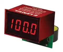
Illustrative purposes only

ACA-20PC-2-AC1-RL-C
Ammeter, ACA-20PC Series, AC Current, 0A to 19.99A, 3.5 Digits, 85 Vac to 264 Vac, LED Display
⚠️ Reference pricing provided. In case of supply shortages, we will connect you with our trusted procurement partners to ensure your project's continuity.
- Manufacturer: MURATA POWER SOLUTIONS
- Product type: Digital Panel Meters
- No. of Digits / Alpha:3-1/2; Meter Function:AC Current; Meter Range:0A to 19.99A; Digit Height:9.4mm; Panel Cutout Height:21.29mm; Panel Cutout Width:33.93mm; Supply Voltage Min:85VAC; Supply V
- SVHC: No SVHC (17-Jan-2022)
- Meter Range: 0A to 19.99A
- Digit Height: 9.4mm
- Product Range: DATEL ACA-20 Series
- Meter Function: AC Current
- Panel Cutout Width: 33.93mm
- Supply Voltage Max: 264VAC
- Supply Voltage Min: 85VAC
- Panel Cutout Height: 21.29mm
- No. of Digits / Alpha: 3-1/2
- Operating Temperature Max: 60°C
- Operating Temperature Min: 0°C
| Delivery and price | |
|---|---|
| Units per pack | 10 |
| Price | 67.43 € |
| Current stock | 10+ |
| Lead time | 30 days |
Datasheet

## **www.murata-ps.com**
## **- ACA 20PC Series**
Digital, LED-Display AC Ammeters with Built-in Current Transformers
**==> picture [49 x 32] intentionally omitted <==**
**----- Start of picture text -----**<br>
Now<br>Available with<br>Wire Lead CTs<br>**----- End of picture text -----**<br>
**==> picture [53 x 8] intentionally omitted <==**
**----- Start of picture text -----**<br>
C® US E156931<br>**----- End of picture text -----**<br>
## **FEATURES**
- Built-in Current Transformers for direct measurement of 0 to 2/20/50/100 Amps
- Functionally complete: On-board current transformers Scaling/interface circuitry Precision A/D converters Bright red LED displays
- 8 different models
- Subminiature, 1.38" x 0.88" package
- Easy-to-read, 0.37"/9.4mm digits
- AC powered models 85-264Vac @ 50/60Hz
- "Self-powered" 85-264Vac, 2A and 20A models feature built-in load connections
- +5-40V dc powered models
2000V isolation; approvals to UL/cUL/IEC/61010-1
Murata Power Solutions' new ACA-20PC Series are the fi rst digital ac ammeters to incorporate on-board current transformers (CT’s), and they are amazingly easy to use. Simply pass the current-carrying load wire through the ACA-20PC’s on-board CT, apply power to the meter's two supply terminals, and you’re instantly measuring ac currents over one of four ranges (0-2A with 1mA resolution, 0-20A with 10mA resolution, or 0-50A and 0-100A with 100mA resolution). Absolutely no external components, such as expensive low-value shunts or 5A "donut" CT’s, are required.
Meters are ac powered (120/220Vac @ 50/60Hz) or dc powered (+5-40V) and impose minimal loads (50mA max. and 120mA max., respectively) on their supplies. All models employ auto-zeroing circuits, precision bandgap references, and super stable thin-fi lm resistors for unsurpassed accuracy (±0.15%FS) and stability.
The functionally complete ACA-20PC ammeters provide all the scaling/interface circuitry to mate the CT’s output to a precision (3½ digit) A/D converter. The A/D's output goes directly to drivers for the meters’ large (0.37"/9.4mm digit height), easy-to-read, LED displays. AC-powered units have on-board AC/DC converters, and wide-range dc-powered units have on-board linear regulators. AC-powered models can be powered by the same ac supply whose current they are monitoring. The 2A and 20A, 85-264Vac, 50/60Hz ("AC1") models feature additional on-board terminal blocks to supply power to the external load. All models provide 2000Vdc isolation between the measured ac current and their power supply, and all are UL/CSA recognized.
Each meter is housed in a subminiature, 1.38" x 0.88", epoxy-encapsulated package. Total behind-the-panel installation depth is approximately 2 inches.
## ~~L~~ **SIMPLIFIED SCHEMATIC DIAGRAM** ~~d~~
**==> picture [519 x 228] intentionally omitted <==**
**----- Start of picture text -----**<br>
CAL.<br>+<br> 3½ DIGIT<br>A/D CONVERTER<br>–<br>+V –V LED DISPLAY<br>RMS-to-DC<br>CONVERTER<br>POWER<br>CONVERTER<br>(L1)<br>BUILT-IN<br>TRANSFORMER CURRENT \ |_| A B Figure 1. ACA-20PC Series simplifi ed schematic<br>\ QO<br>TB1<br>MEASURED AC CURRENT LIMITED<br>COMPLIANT For full details go to LOAD CURRENT AC OR DC SUPPLY<br>gy www.murata-ps.com/rohs ©<br>**----- End of picture text -----**<br>
**www.murata-ps.com/support**
**MPM_ACA_20PC.C01** Page 1 of 6
## **- ACA 20PC Series**
Digital, LED-Display AC Ammeters with Built-in Current Transformers
## **Performance/Functional Specifi cations**
Typical at TA = +25°C, unless otherwise noted. ➀
**==> picture [244 x 602] intentionally omitted <==**
**----- Start of picture text -----**<br>
Full-Scale Current (45-450Hz) ➁ Min. Typ. Max. Units<br>ACA-20PC-1-XXX-XX – – 1.999 Amps<br>ACA-20PC-2-XXX-XX ➂ – – 19.99 Amps<br>ACA-20PC-3-XXX-XX – – 50.0 Amps<br>ACA-20PC-4-XXX-XX – – 100.0 Amps<br>DMS-30798-C – – 30.0 Amps<br>Overcurrent Rating ➁ 1.5 x rated full-scale current<br>Performance<br>Sampling Rate 2.5 reading per second<br>Accuracy ➁ ±0.15%FS ±6 Counts<br>Measurement Type Sine wave input, full-wave averaging,<br>rms calibrated<br>Temperature Drift (0 = +60°C) – ±0.2 ±0.4 Cnts/°C<br>Zero Reading (Vin = 0 Volts) “–001” “000” “001” Counts<br>Dielectric Withstanding Voltage 2000 – – Vdc<br>UL/IEC61010-1 Measurement category II<br>Power Supply Voltage ➄<br>ACA-20PC-X-AC1-RL (47-99Hz) 85 120 264 Vac<br>ACA-20PC-X-DC1-RL +4.75 – +40 Vdc<br>Power Supply Current ➃<br>ACA-20PC-X-AC1-RL (47-99Hz) – 30 50 mA<br>ACA-20PC-X-DC1-RL – +8 +12 mAdc<br>Power Supply Terminal Block<br>ACA-20PC-1-AC1-RL and ACA-20PC-2-AC1-RL<br>(2A and 20A ac-powered models with 4-position terminal blocks):<br>Wire Size and Type 12-20AWG (solid), 14-20AWG (stranded)<br>Insulation Strip Length 0.25 inches<br>Screw Tightening Torque 4.4 lb·in (0.5N·m) ±20%<br>Maximum Rated Current 20A with 12AWG solid wire; 15A with<br>14AWG solid or stranded wire<br>Maximum Rated Voltage 630V (VDE 0110-V. Group 2)<br>250V (VDE 0110-V Group 3)<br>ACA-20PC-X-XXX-XX<br>(All other ac or dc-powered models with 2-position terminal blocks):<br>Wire Size and Type 16-24AWG (solid or stranded)<br>Insulation Strip Length 0.25 inches<br>Screw Tightening Torque 2.2 lb·in (0.25 N·m) ±20%<br>Display<br>Display Type and Size 3½ digit, 0.37"/9.4mm high LED<br>Overrange Indication “1_ _ _”<br>Decimal Point Fixed, model dependent<br>Physical/Environmental<br>Operating Temperature 0 – +60 °C<br>Storage Temperature –40 – +75 °C<br>Humidity (non-condensing) 0 – 95 %<br>**----- End of picture text -----**<br>
|**Physical/Environmental**|**Physical/Environmental**|
|---|---|
|**Case Material**|Polycarbonate|
|**Dimensions**|1.38”W x 0.88”H. Depth is model depen-<br>dent (see mechanical specif cation)|
|**Weight:**||
|**ACA-20PC-1-XXX-XX**|1.1 ounces (31 grams)|
|**ACA-20PC-2-XXX-XX**|1.1 ounces (31 grams)|
|**ACA-20PC-3-XXX-XX**|1.3 ounces (37 grams)|
|**ACA-20PC-4-XXX-XX**|1.5 ounces (43 grams)|
|**DMS-30798-C**|1.0 ounces (28 grams)|
- ➀ The ACA-20PC-1-AC1-RL and ACA-20PC-2-AC1-RL have 4-position on-board terminal blocks. All other models have 2-position terminal blocks.
- ➁ Specifi ed full-scale currents are those passing through the built-in CT's primary(load) circuit, over the frequency of 45-450Hz. The Overcurrent Rating is a continuous rating that applies to the measured ac load current. It does not apply to any circuitry external to the meter. Accuracy is guaranteed to the rated current.
- ➁ For the ACA-20PC-2-AC1-RL, if the load is connected to the meter's on-board 4-position terminal block, the 20A full scale range requires 12AWG solid copper wire on all connections. If 14AWG solid copper wire is used, the current should be limited to 15A. See Figure 3.
- ➃ All specifi ed maximum power supply currents are steady-state values. AC-powered models can draw higher surges at initial turn-on.
- ➄ Maximum reverse polarity protection on "DC1" models is –40Vdc.
## **Ordering Information**
## **ACA - 20PC - 1 - AC1 - RL - L - C**
**==> picture [215 x 91] intentionally omitted <==**
**----- Start of picture text -----**<br>
(45-450Hz) RoHS<br>Input Range: Leaded CT (100A model)<br>1 = 1.999A<br>LED Color:<br>2 = 19.99A RL = Red Standard<br>3 = 50.0A BL = Blue Standard<br>4 = 100.0A Power Supply: PGL = Green Standard<br>AC1 = 85-264Vac@50/60Hz<br>DC1 = +5-40Vdc<br>**----- End of picture text -----**<br>
**See www.murata-ps.com/dpm-availability for model-specifi c availability.**
**DMS-30798-C:** 30Amp model with a wire lead CT and “-AC1” power supply specifi cations. See Mechanical section for dimensions.
**Accessories:** DMS-20-CP Panel cutout punch
A DMS-BZL4-C bezel assembly with sealing gasket is supplied with each ammeter.
## **www.murata-ps.com/support**
**MPM_ACA_20PC.C01** Page 2 of 6
## **- ACA 20PC Series**
Digital, LED-Display AC Ammeters with Built-in Current Transformers
## **TECHNICAL NOTES**
**IMPORTANT!** To ensure safe and reliable operation, ACA-20PC ammeters must be installed and serviced by qualifi ed technical personnel. Contact Murata Power Solutions if there is any doubt regarding ammeter installation and/or operation.
**1. Measurement Type** : ACA-20PC ac ammeters employ a full-waverectifi ed, average responding, rms-calibrated circuit to measure the stepped-down output of their on-board, L1 current transformer (CT) . Stated accuracy specifi cations are measured using a sine-wave current at or close to the specifi ed full scale input level, at nominal line frequency.
**2. Calibration** : Periodic recalibration of ACA-20PC ammeters is not required under normal, indoor operating environments. If user calibration is necessary, it should be performed by qualifi ed technical personnel. Calibration is performed with potentially lethal voltages applied to the ACA-20PC and its associated wiring, with the specifi ed full-scale current fl owing through the ammeter’s built-in current transformer.
A plastic, fully insulated adjusting tool must be used to access the recessed calibration potentiometer located on the back of the meter (see Mechanical Specifi cations). Contact Murata Power Solutions if additional information is required regarding calibration, setup, or any other technical issue pertaining to the ACA-20PC.
**3. Wire Gauges and Fusing** : Wires specifi ed in the Functional Specifi - cations section must be used for making connections to ACA-20PC Series ammeters. All power-supply and load wiring must be rated for the supply voltages and currents they will conduct and must comply with any code or application-mandated requirements pertaining to the user’s specifi c installation.
ACA-20PC Series ammeters are not internally fused. Special attention must be paid to ACA-20PC-1-AC1 (0-2A range) and ACA-20PC-2-AC1 (0-20A range) ac-powered models when their built-in auxiliary terminal block connections on TB1 are used to supply power to an external load. The input supply wires connected to both the ammeter and the load must be fused according to the current rating of the wire gauge being used, in accordance with applicable regulatory codes, but not to exceed TB1’s maximum 20A rating. If TB1 is not used to supply power to external loads, a 0.25A/250V time delay/time lag fuse must be used.
ACA-20PC-3-AC1 (0-50A range, ac-powered) and ACA-20PC- 4-AC1 (0-100A, ac-powered) models’ TB1 is to be used only for powering the ammeters’ internal circuitry; it must not be used to supply power to external loads. The supply wires feeding these models must be fused with a 0.25A time delay/time lag fuse, in accordance with applicable regulatory codes.
Wire insulation must be stripped to within ±10% of the stated dimensions, and wires should be inserted into TB1 such that their insulation is not pinched by the screw terminal.
**4. AC Supply Polarity and Grounding** : The two ac supply inputs, TB1-A and TB1-B, on ac-powered ammeters are not in themselves polarity sensitive, that is, they have no internal "AC LO" or "AC HI"
designations. Also, ac-powered ACA-20PC ammeters do not include or require a connection to earth/chassis ground. However, in many applications, external ac loads which are connected directly to the ACA-20PC’s built-in auxiliary terminal blocks must be wired with proper polarity and connected to earth/chassis ground.
**5. Connector Torque Ratings** : It is important to tighten TB1's screw terminals to their rated torque specifi cations of 4.4 pound-inches (0.5Nm) for four-terminal ammeters (ACA-20PC-1-AC1-RL and ACA20PC-2-AC1-RL), and 3.6 pound-inches (0.4Nm) for two-terminal ammeters. Proper tightening will minimize connector losses and ensure safe, reliable operation.
**6. 100 Amp Model (ACA-20PC-4-XXX)** : This model’s built-in current transformer requires a larger panel cutout width dimension. See Mechanical Specifi cations for more information.
**7. DC-Powered Models** : DC-powered models draw minimal supply currents and in most applications can be fused according to the supply wire’s maximum amperage rating. However, be sure to check and comply with all applicable codes and regulations to ensure proper installation and operation.
**8. Isolation** : The on-board CT (L1) provides a minimum 2000Vdc isolation between the current-carrying conductor passing through its primary circuit and the ammeter supply voltage connected to TB1. Of course, this isolation rating only applies to applications in which the load wiring (i.e., the wire passing through the CT’s center hole) does not connect directly or indirectly to TB1-A or TB1-B.
## **PANEL INSTALLATION**
## **All connections to ACA-20PC Series ammeters must be made after the ammeter is securely attached to the panel and with all load and supply voltages de-energized (off).**
Care should be exercised when passing the load-carrying conductor through the meter’s built-in CT—particularly when larger-gauge conductors are used. The position of the installed wire should be such that minimal forces are applied to the built-in CT, TB1, or to the ammeter itself. In high-vibration environments, adequate strain reliefs be used for all load and supply wiring.
To ensure a secure panel-mount installation, Murata Power Solutions recommends using the DMS-BZL4 bezel assembly (with sealing gasket) supplied with each ammeter. Also, please note that the ACA20PC-4-XXX 100A oversize CT requires a larger panel-cutout width of 1.350" (34.3mm). See Mechanical Specifi cations for detailed cutout and ammeter dimensions.
Following the four-step sequence shown in Figure 2 below—being careful not to apply excessive force or twisting motions—insert the ammeter into the panel opening. When using the DMS-BZL4 bezel assembly, install its sealing gasket so it is positioned between the ammeter’s front fl ange and panel front surface (see Mechanical Specifi cations). Be sure to use and securely tighten all four screws supplied with the bezel assembly.
**www.murata-ps.com/support**
**MPM_ACA_20PC.C01** Page 3 of 6
## **- ACA 20PC Series**
Digital, LED-Display AC Ammeters with Built-in Current Transformers
**==> picture [440 x 22] intentionally omitted <==**
**----- Start of picture text -----**<br>
Step 1. Step 2. Step 3. Step 4.<br>Panel<br>**----- End of picture text -----**<br>
**==> picture [85 x 9] intentionally omitted <==**
**----- Start of picture text -----**<br>
Figure 2. Panel Installation<br>**----- End of picture text -----**<br>
## **TYPICAL WIRING DIAGRAM**
**First pass and carefully dress one external load wire through the on-board CT (L1). Then connect the ac supply and load wires to TB1 as shown. If required, verify that correct line-power polarities are applied to the external load (see Technical Note 4). Ensure all wires are stripped and terminals torqued correctly. For proper operation, pass only one load wire through the on-board CT’s center hole.**
**==> picture [237 x 213] intentionally omitted <==**
**----- Start of picture text -----**<br>
FUSED FUSED<br>85-264Vac 85-264Vac<br>POWER POWER<br>ACA-20PC-1-AC1-RL<br>ACA-20PC-2-AC1-RL<br>E<br>85-264Vac TO LOAD TO LOAD<br>Figure 3. 2A and 20A, 85-264V AC-Powered Models<br>With Auxilliary Load Connections<br>**----- End of picture text -----**<br>
**==> picture [139 x 159] intentionally omitted <==**
**----- Start of picture text -----**<br>
FUSED<br>AC POWER<br>SUPPLY<br>ACA-20PC-X-ACX<br>TO AC LOAD<br>AC SUPPLY<br>**----- End of picture text -----**<br>
**Figure 4. All Other AC-Powered Models**
**==> picture [142 x 169] intentionally omitted <==**
**----- Start of picture text -----**<br>
+<br>FUSED<br>DC POWER<br>SUPPLY<br>–<br>ACA-20PC-X-DCX<br>+ –<br>TO AC LOAD<br>AC SUPPLY<br>**----- End of picture text -----**<br>
**Figure 5. All DC-Powered Models**
**www.murata-ps.com/support**
**MPM_ACA_20PC.C01** Page 4 of 6
## **- ACA 20PC Series**
Digital, LED-Display AC Ammeters with Built-in Current Transformers
## **MECHANICAL SPECIFICATIONS**
## **ACA-20PC-1 & 2-AC1-RL**
**==> picture [125 x 8] intentionally omitted <==**
**----- Start of picture text -----**<br>
2A and 20A, 85-264V ac-powered models<br>**----- End of picture text -----**<br>
**ACA-20PC-1 & 2** 2A and 20A, all other models
**==> picture [468 x 171] intentionally omitted <==**
**----- Start of picture text -----**<br>
Hole Diameter: Hole Diameter:<br>0.27 (6.9) min. 0.27 (6.9) min.<br>2.01 2.01<br>(51.1) (51.1)<br>1.00 1.00<br>0.040 (25.4) 0.040 (25.4)<br>(1.02) (1.02)<br>0.040(1.02) (33.0)(35.1)1.301.38 0.040(1.02) (20.3)(22.4)0.800.88 0.040(1.02) (33.0)(35.1)1.301.38 0.040(1.02) (20.3)(22.4)0.800.88<br>1.32 1.32<br>ie } (33.5) ie} (33.5)<br>FRONT VIEW BACK VIEW FRONT VIEW BACK VIEW<br>CAL. CAL.<br>**----- End of picture text -----**<br>
**==> picture [479 x 323] intentionally omitted <==**
**----- Start of picture text -----**<br>
CAL. CAL.<br>of ce qT Gg oe? &e I Gg<br>ACA-20PC-3 Series ACA-20PC-4 Series<br>100A models with pc-board mounted CTs<br>* * [THIS MODEL REQUIRES A PANEL]<br>(33.8)1.33 CUTOUT WIDTH OF 1.350" (34.3MM)<br>Hole Diameter:<br>0.35 (8.9) min.<br>Hole Diameter: , o o<br>0.55 (14.0) min.<br>2.12 2.53<br>(53.8) (64.3)<br>0.040(1.02) (25.4)1.00 0.040(1.02) (25.4)1.00<br>0.040(1.02) sl (33.0)(35.1)1.301.38 0.040(1.02) (20.3)(22.4)0.800.88 (39.1)1.54 0.040(1.02) ee0) (33.0)(35.1)1.301.38 0.040(1.02) e. (20.3)(22.4)0.800.88 (33.5)1.32<br>FRONT VIEW BACK VIEW FRONT VIEW BACK VIEW<br>CAL. CAL.<br>**----- End of picture text -----**<br>
**ACA-20PC-3 Series** 50A models
**www.murata** Mechanical Dimensions: Inches (mm) Tolerances: 2 PL DEC ±0.02 (±0.51), 3 PL DEC ±0.010 (±0.254) **-ps.com/support**
**MPM_ACA_20PC.C01** Page 5 of 6
## **- ACA 20PC Series**
## Digital, LED-Display AC Ammeters with Built-in Current Transformers
## **MECHANICAL SPECIFICATIONS, CONTINUED**
## **BEZEL INSTALLATION AND RECOMMENDED DRILL AND PANEL CUTOUT**
**==> picture [508 x 336] intentionally omitted <==**
**----- Start of picture text -----**<br>
#2-56 INSERT 0.187<br>ACA-20PC-4-XXX-L (100A model) 0.156 (3.96) DEEP (4.75)<br>DMS-30798-C (30A model) 0 — 7<br>OD: 100A Model: 1.18 (30.0) DMS-30798-C (30A): 0.87 (22.0) FRONT VIEW (32.51)1.280<br>ID: 100A Model: 0.58 (14.7)<br> DMS-30798-C (30A): 0.35 (8.9)<br>— 1.826 (46.38) oe<br>0.116 (2.95)<br>9[ Lead Length:2.0 (50.5) min. INTERNAL CORNER RADII:0.032 (0.81) MAX.<br>1.07 0.838<br>(27.18) PANEL CUTOUT (21.29)<br>fat 1.00 Ty<br>0.040 (25.4)<br>(1.02)<br>0.093 (2.362) DIA 1.336 (33.93)* 0.145 (3.68)<br>(4 REQUIRED) 1.626 (41.30)<br>0.040(1.02) HL) (33.0)1.301.38 0.040(1.02) (20.3)0.800.88 | eae * 1.350 (34.3) for ACA-20PC-4-XXX 100A model<br>(35.1) (22.4) with pc-board mounted CTs.<br>1.14<br>re (29.0) ~~<br>FRONT VIEW BACK VIEW<br>CAL.<br>Gasket<br>**----- End of picture text -----**<br>
**ACA-20PC-4-XXX-L (100A model) DMS-30798-C (30A model)**
0.116 (2.95)
**==> picture [71 x 32] intentionally omitted <==**
**----- Start of picture text -----**<br>
® BEZEL<br>**----- End of picture text -----**<br>
## **1. Description of safety marks:**
Caution, risk of electrical shock
Caution, risk of danger
Equipment is protected throughout by double or reinforced insulation
## **2. Cleaning Instructions: Gently clean with dry cloth only.**
## **3. Caution: if the equipment is used in a manner not specifi ed by Murata Power Solutions, the protection provided by the equipment may be impaired.**
Murata Power Solutions, Inc. 11 Cabot Boulevard, Mansfi eld, MA 02048-1151 U.S.A. ISO 9001 and 14001 REGISTERED
**This product is subject to the following operating requirements and the Life and Safety Critical Application Sales Policy: Refer to: http://www.murata-ps.com/requirements/**
Murata Power Solutions, Inc. makes no representation that the use of its products in the circuits described herein, or the use of other technical information contained herein, will not infringe upon existing or future patent rights. The descriptions contained herein do not imply the granting of licenses to make, use, or sell equipment constructed in accordance therewith. Specifi cations are subject to change without notice. _**© 2015 Murata Power Solutions, Inc.**_
**www.murata-ps.com/support**
**MPM_ACA_20PC.C01** Page 6 of 6
Updated at June 9, 2026
About Novapart
Novapart is a B2B electronic component broker specialising in stock shortages and cost reduction. We source hard-to-find parts and identify compliant alternatives across a catalogue of 410,000+ components from 500+ manufacturers.
Learn more →Stock Shortage Specialist
When a component is unavailable, discontinued or has an unacceptable lead time, we tap into our network of vetted European and Asian distributors to source what you need — without compromising on quality or traceability.
Request a quote →Compliant Alternatives
We identify pin-to-pin, electrically equivalent substitutes that meet the same certifications (RoHS, AEC-Q100, REACH) as your original specification — validated against datasheets, not just part numbers. Often at a lower cost.
BOM Analysis service →