
Image not available
Illustrative purposes only

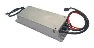
ABS400-1048
AC/DC Enclosed Power Supply (PSU), ITE & Medical, 1 Outputs, 400 W, 48 VDC, 8.3 A
⚠️ Reference pricing provided. In case of supply shortages, we will connect you with our trusted procurement partners to ensure your project's continuity.
- Manufacturer: BEL POWER SOLUTIONS
- Product type: AC / DC Enclosed Power Supplies
- SVHC: To Be Advised
- Product Range: ABS400 Series
- No. of Outputs: 1Outputs
- Output Power Max: 400W
- Current, Output 4: -
- Input Voltage VAC: 90V AC to 264V AC
- Power Supply Output Type: Adjustable, Fixed
- Output Current - Output 1: 8.3A
- Output Current - Output 2: -
- Output Current - Output 3: -
- Output Voltage - Output 1: 48VDC
- Output Voltage - Output 2: -
- Output Voltage - Output 3: -
- Output Voltage - Output 4: -
- Power Supply Applications: ITE & Medical
| Delivery and price | |
|---|---|
| Units per pack | 5 |
| Price | 277.35 € |
| Current stock | 10+ |
| Lead time | 30 days |
Datasheet

The ABS400 Series of AC-DC power supplies provides up to 400 W of regulated output power through wide input voltage range 90 – 264 VAC in single outputs of 12, 24, 36 or 48 VDC.

The ABS400 Series comes in a 83.0 x 212.0 x 42.0 mm form factor, offering 12 and 5 VSB standby outputs and a full set of protection features. Available control signals include Power Good (Power_OK), remote On/off (PS_ON) and remote sense (+RS).

The sealed and full potted package allows an IP67 ingress protection index and can be installed in contact with thermoconductive part of the system to transfer heat by conduction.

The ABS400 Series complies with the latest international safety standards for Audio Video and IT equipment and displays the CE-Mark for the European Low Voltage Directive (LVD).

- Universal input voltage range (90 – 264 VAC)

- Input surge current limiting

- 400 W rated power (440 W peak up to 10 s)

- • High efficiency up to 94%

- Low stand-by consumption (<0.5 W)

- 12, 24, 36 and 48 V standard output voltages

- Active PFC, EN61000-3-2 compliant (Class C, >25% load).

- • Low earth / touch leakage current

-

   - Over temperature protection, OV, OC and SC protections

- Stand by +5 V, 2 A and auxiliary / fan 12 VDC, 1 A outputs.

- • Remote On / Off signal

-

   - Power good and remote sense signals

- Sealed, potted package IP67 rated, fits 1U applications

-

-

-

   - UL/IEC 60950-1 and UL/IEC 62368-1 safety approval

   - RoHS 3 compliant (Directive 2015/863/EU)

   - 4000 m altitude operation

- Optional heatsink accessory available (HSKIT-400-XBS)

- • Suitable for harsh environments

## Applications • Video Wall Displays •

Entertainment Lighting

Industrial & Process Control

-

   - Telecommunications

-

   - Laboratory Equipment

-

   - Test & Measurement Equipment

-

- Class II outdoor signage

Please read our datasheet & drawing disclaimer here.

ABS400 Series

2

|||**INPUT VOLTAGE**|**INPUT VOLTAGE**<br>**NOM. OUTPUT**|**NOM. OUTPUT**<br>**MAX. OUTPUT**|**MAX. OUTPUT**||
|---|---|---|---|---|---|---|
|**MODEL NUMBER**|**MODEL NUMBER**<br>**PACKAGE & COOLING**|**RANGE**|**VOLTAGE**|**POWER**|**CURRENT**|**DIMENSIONS**|
|||**[VAC]**|**[VDC]**|**[W]**|**[A]**||
|ABS400-1012|Sealed Chassis<br>Convection / Conduction|90 - 264|12|400|33.3|Dimensions without<br>heatsink:|
|ABS400-1024|Sealed Chassis<br>Convection / Conduction|90 - 264|24|400|16.7|83.0 x 212.0 x 42.0 mm<br>3.27 x 8.34 x 1.65 in|
|ABS400-1036|Sealed Chassis<br>Convection / Conduction|90 - 264|36|400|11.1|Dimensions with<br>heatsink:|
|ABS400-1048|Sealed Chassis<br>Convection / Conduction|90 - 264|48|400|8.3|83.0 x 212.0 x 70.1 mm<br>3.27 x 8.34 x 2.76 in|
|HSKIT-400-XBS|- Heatsink accessory (optional)|- Heatsink accessory (optional) Mounting kit includes 4x screws, M4x10, and the thermally conductive graphite sheet|||||


|**PARAMETER**|**DESCRIPTION / CONDITION**|||**MIN**|**NOM**|**MAX**|**UNIT**|
|---|---|---|---|---|---|---|---|
|AC Input Voltage|PS starts and operates at 90 VACat all load conditions|||90|100-240|100-240<br>264|VRMS|
|DC Input Voltage||||170|-|270|VDC|
|Input Frequency||||47|50/60|440|Hz|
|Input Current|RMS at 180 VAC, maximum load, 50 / 60 Hz<br>RMS at 90 VAC, maximum load, 50 / 60 Hz|||-|-|2.5<br>5.0|A|
|Inrush Current|265 VAC, 25 °C ambient, cold start.|||||20|A|
|Fusing|2x Time Lag 6.3 A, 250 V on both L and N||2x Time Lag 6.3 A, 250 V on both L and N|-|-|6.3|A|
||||20% rated load|90|-|-||
||At 115 VAC||100 % load|92|-|-||
|Efficiency|||20% full load|90|-|-|%|
||At 230 VAC||50 – 100 % full load|94|-|-||
|Input Power Consumption|Power on, 115-230 VRMS, no load<br>Stand by, 115-230 VRMS, no load|||-<br>-|1<br>0.4|1.5<br>0.5|W|
|Power Factor|At full rated load, 115 VAC, 60 Hz and 230 VAC, 50 Hz input voltages||At full rated load, 115 VAC, 60 Hz and 230 VAC, 50 Hz input voltages|0.95|-|-|-|
|Harmonic Current|Complies with EN-61000-3-2 Class C at 230 VAC  50 Hz, load >50 W.|Complies with EN-61000-3-2 Class C at 230 VAC  50 Hz, load >50 W.||||||
|Fluctuations and Flicker|Complies with EN-61000-3-3 at nominal voltages and full load.|Complies with EN-61000-3-3 at nominal voltages and full load.||||||
|Leakage Current|Normal conditions, 240 VRMS, 60 Hz.|||||300|µA|


tech.support@psbel.com

ABS400 Series

3

|**PARAMETER**|**DESCRIPTION / CONDITION**||||||**MIN**|**NOM**|**MAX**|**UNIT**|
|---|---|---|---|---|---|---|---|---|---|---|
||||||||-|12|-||
|V1 Output Voltage|±0.5% set point accuracy on all outputs||±0.5% set point accuracy on all outputs||||-<br>-|24<br>36|-<br>-|V|
||||||||-|48|-||
||All models, convection cooling|All models, convection cooling|||||-|-|350||
|V1 Output Power Rating|All models, conduction cooling / heat sink|All models, conduction cooling / heat sink||All models, conduction cooling / heat sink|||-|-|400|W|
||All models, peak power (≤10 s)||||||-|-|440||
||||||V1: 12 VDC||||33.3||
||* Conduction (with heatsink)||||V1: 24 VDC<br>V1: 36 VDC||||16.7<br>11.1|A|
|V1 Output Current|||||V1: 48 VDC<br>V1: 12 VDC||||8.3<br>29.2||
||** Convection (without heatsink)||** Convection (without heatsink)||V1: 24 VDC<br>V1: 36 VDC||||14.6<br>9.7|A|
||||||V1: 48 VDC||||7.3||
|V1 Voltage Adjustment Range|||||||±5|-|-|%V1|
||||V1 Load: 0 – 33.3 A (12 V)|V1 Load: 0 – 33.3 A (12 V)|V1 Load: 0 – 33.3 A (12 V)|V1 Load: 0 – 33.3 A (12 V)|||||
||||0 – 16.7 A (24 V)|0 – 16.7 A (24 V)|0 – 16.7 A (24 V)|0 – 16.7 A (24 V)|||||
|V1 Load-Line-Cross Regulation|VAC: 90 – 264 VRMS||0 – 11.1 A (36 V)|0 – 11.1 A (36 V)|0 – 11.1 A (36 V)<br>0 – 8.3 A (48 V)|0 – 11.1 A (36 V)<br>0 – 8.3 A (48 V)|-|-|±2|%V1|
|||||V2 Load:   0 – 1 A||V2 Load:   0 – 1 A|||||
|||||5VSBLoad: 0 – 2 A||Load: 0 – 2 A|||||
|V1 Line Regulation|VAC: 90 – 264 VRMS||||||-|-|±0.1|%V1|
||25% load changes at 1 A/µs||||||||||
|Transient Response<br>(Voltage Deviation)<br>V1, 5VSB|12 V at 2200 µF Load / IOUT> 0.5 A<br>24 V at 1000 µF Load / IOUT> 0.5 A<br>36 V at 820 µF Load / IOUT> 0.5 A<br>48 V at 560 µF Load / IOUT> 0.5 A||||||-|-|±5|%V1<br>%5VSB|
||5VSBat 560 µF Load / IOUT> 0.1 A||||||||||
|V1 Ripple & Noise|All models, Peak-to-peak, 20 MHz BW.<br>100 nF ceramic and 10µF tantalum to the load.||||100 nF ceramic and 10µF tantalum to the load.||-|-|1|%V1|
|Start-up Rise Time|90<VIN<264, any load conditions.||||||5|-|85|ms|
||V1 in regulation after PS_ON is asserted|V1 in regulation after PS_ON is asserted|||||||200||
|Start-up Delay|V1 in regulation after AC is applied||||||-|-|750|ms|
||5VSBin regulation after AC is applied||||||||500||
|||||||||10||%V1|
|Turn-on Overshoot|At 500 mA output current, V1 in regulation within 50 ms.||At 500 mA output current, V1 in regulation within 50 ms.||||-|10|-|%V2|
|||||||||10||%VSB|
||At nominal VIN, 400 W, for all outputs|||, 400 W, for all outputs|||-|16|-||
|Hold-up Time|At nominal VIN, 365 W, for all outputs|||, 365 W, for all outputs|||-|20|-|ms|
||At nominal VIN, 200 W, for all outputs|||, 200 W, for all outputs|||-|35|-||
|Minimum Load ***|All models; V1, V2 and 5VSB||||||0|-|-|A|
|||||||12 V|-|-|33000||
|Maximum Load Capacitance|At nominal VIN, 25 °C ambient|||||24 V<br>36 V|-<br>-|-<br>-|16000<br>10000|µF|
|||||||48 V|-|-|7000||
|Temperature Drift|||||||-1.2|-|+1.2|mV/°C|
||All versions.||||||||||
|V2 Output Voltage|Load on V2: from 5 to 1000 mA||Load on V2: from 5 to 1000 mA||||11.25|12.5|13.75|V|
||Load on V1: from 0.1 to 16.7 A|Load on V1: from 0.1 to 16.7 A|||||||||
|V2 Output Current|All models, convection/forced air cooling||||||-|-|1|A|
|V2 Ripple|Peak-to-Peak measured at 20 MHz Bandwidth.||||||||240|mV|
|5VSBOutput Voltage|All models (3% set point accuracy)||||||-|5|-|V|
|5VSBOutput Current|All models, convection cooling<br>All models, conduction cooling / heat sink|All models, convection cooling<br>All models, conduction cooling / heat sink||All models, conduction cooling / heat sink|||-<br>-|-<br>-|1.5<br>2|A|


**==> picture [51 x 30] intentionally omitted <==**

**----- Start of picture text -----**<br>
rete st<br>c@%SO ee,<br>**----- End of picture text -----**<br>


**Asia-Pacific Europe, Middle East North America** +86 755 298 85888 +353 61 49 8941 +1 866 513 2839

© 2022 Bel Power Solutions & Protection

BCD.01062_D

ABS400 Series

4

|4|||ABS400 Series|ABS400 Series|ABS400 Series|ABS400 Series|
|---|---|---|---|---|---|---|
|||V1 Load: 0 – 33.3 A (12 V)|||||
|||0 – 16.7 A (24 V)|||||
|5VSBLoad-Line-Cross<br>Regulation|VAC: 90 – 264 VRMS|0 – 11.1 A (36 V)<br>0 – 8.3 A (48 V)|-|-|±5|%5VSB|
|||V2 Load:   0 – 1 A|||||
|||5VSBLoad: 0 – 2 A|||||
|5VSBRipple|Peak-to-Peak measured at 20 MHz Bandwidth.|Peak-to-Peak measured at 20 MHz Bandwidth.|||50|mV|


- The combined output power of V1, V2 and 5VSB for all models, when conduction cooled or convection cooled with heat sink mounted, must not exceed 400 W up to 50 °C, and 300 at 70 °C ambient temperature.

- ** The combined output power of V1, V2 and 5 VSB for all models, when convection cooled and VIN ≥ 180 VRMS, must not exceed 350 W up to 50 °C, and 240 W at 70 °C ambient temperature. See de-rating curves below.

- *** When the load on the main output is less than 100 mA, V2 output voltage might regulate below its minimum value. Contact Bel for details.

Sealed Box without Heatsink

**==> picture [93 x 7] intentionally omitted <==**

**----- Start of picture text -----**<br>
Sealed Box with Heatsink<br>**----- End of picture text -----**<br>


Figure 2. Power Derating Curves

**==> picture [52 x 15] intentionally omitted <==**

**----- Start of picture text -----**<br>
ee<br>**----- End of picture text -----**<br>


tech.support@psbel.com

5

## ABS400 Series

Base signals and controls are accessible from signal connector P204.

|**SIGNAL**|**DESCRIPTION / CONDITION**|**MIN**|**NOM**|**MAX**|**UNIT**|
|---|---|---|---|---|---|
|**PS_ON**|Active low, +5 V TTL signal compatible. Input low voltage|0|-|2.0|V|
||Input high voltage (IIN= 200 µA)|3.0|-|-|V|
||V1 and V2 disabled when PS_ON is open|||||
||5VSBnot affected by PS_ON|||||
||V1 and V2 enabled with PS_ON connected to RTN|||||
|**P_OK**|+5 V TTL compatible|||||
||Logic level low (<10 mA sinking)|-|-|0.7|V|
||Logic level high (100 µA sourcing)|2.4|-|5|V|
||Low to high time after V1 in regulation|0.05|-|0.1|s|
||Power down warning time|1|-|-|ms|
|**5VSB output**|Active and in regulation after a 90<VAC<264 is applied|-|-|200|ms|
||5VSBnot affected by PS_ON|||||


Above waveforms are expected with AC Input ON/OFF:

|Standbyon - Main outputs on|50 ms≤T1≤250 ms|
|---|---|
|Main output Rise Time|5 ms≤T2≤110 ms|
|5 VSBrise time|4 ms≤T10≤20 ms|
|Main outputs On – P_OK delay|25 ms≤T3≤100 ms|
|Power down warning 1|T4≥1 ms|
|Main Output off – Standbyoff2|T5≥1.2 s|
|Hold-uptime(AC off – P_OK low)|T6≥15 ms(115/ 230 VAC)|
|AC_ON - Standbyturn on time|T7≤500 ms|


**Asia-Pacific Europe, Middle East North America** +86 755 298 85888 +353 61 49 8941 +1 866 513 2839

© 2022 Bel Power Solutions & Protection

BCD.01062_D

ABS400 Series

6

Above waveforms are expected with PS_ON Signal ON/OFF state change:

|Main Output Rise Time|5 ms≤T2≤110 ms|
|---|---|
|Main Outputs on – P_OK delay|25 ms≤T3≤100 ms|
|Power down warning1|1 ms≤T4≤5 ms|
|PS_ON - Main Output(off)Timing|T8≤1 ms|
|PS_ON - Main Output(on)Timing|T9≤200 ms|


1 T4 parameter measurement setup will assume at least 10% of the maximum load on each output.

2 T5 parameter measurement setup will assume 50% of the maximum load on 5VSB.

|**PARAMETER**|**DESCRIPTION / CONDITION**|**MIN**|**NOM**|**MAX**|**UNIT**|
|---|---|---|---|---|---|
|Input Under Voltage|Auto-recovering, hiccup mode.|60|75|-|VAC|
|Input Fuse|2x Time Lag 6.3 A, 250 V on L and N|-|-|6.3|A|
|Over Current|At nominal input voltages.<br>V1: Hiccup mode. auto-recovering.<br>V2: PTC limiting, auto-recovering.|110|-|155|%I1MAX|
||5VSB: Hiccup mode, auto-recovering.|||||
||At nominal input voltages.|||||
|Short Circuit|V1: Hiccup mode. auto-recovering.<br>V2: PTC limiting, auto-recovering.|-|-|-||
||5VSB: Hiccup mode, auto-recovering.|||||
||12V|||||
||24V|||||
|Over Voltage|48V|110|-|136|%VNOM|
||5VSB|||||
||Shut down, latch-off.|||||
|Over Temperature (on primary stage)|Shut down, latch off.|-|-|-||
|Over Temperature (on secondary side)|Hiccup mode, auto-recovering.|-|-|-||
|Isolation Primary to Secondary|Reinforced (2x MoPP)|5660<br>4000|-<br>-|-<br>-|VDC<br>VAC|
|Isolation Input to Earth|Basic (1x MoPP)|1500|||VAC|
|Isolation V1 to V2|Functional|100|-|-|VDC|
|Isolation Output to Earth|Basic (1x MoPP)|1500|-|-|VAC|


**==> picture [52 x 29] intentionally omitted <==**

**----- Start of picture text -----**<br>
aewf Sena st<br>**----- End of picture text -----**<br>


tech.support@psbel.com

7

## ABS400 Series

|**PARAMETER**|**DESCRIPTION / CONDITION**|**MIN**|**NOM**|**NOM**|**MAX**|**UNIT**|
|---|---|---|---|---|---|---|
|Operating Temperature Range|PS starts up at -30 °C<br>See graphs above for output power de-rating against TAmband VIn.|-20|-||70|°C|
|Storage Temperature Range||-40|-||85|°C|
|Humidity|RH, Non-condensing Operating<br>Non-operating|-|-||90<br>95|%<br>%|
|Operating Altitude||-|-||4000|m|
||**EN 60068-2-27**||||||
|Shock|Operating: Half sine, 30 g, 18 ms, 3 axes, 6x each (3 positive and 3 negative).|Operating: Half sine, 30 g, 18 ms, 3 axes, 6x each (3 positive and 3 negative).||Operating: Half sine, 30 g, 18 ms, 3 axes, 6x each (3 positive and 3 negative).|||
||Non-Operating: Half sine, 50 g, 11 ms, 3 axes, 6x each (3 positive and 3 negative).||Non-Operating: Half sine, 50 g, 11 ms, 3 axes, 6x each (3 positive and 3 negative).||||
||**EN 60068-2-64**||||||
|Vibration|Operating: Sine,10 – 500 Hz, 1 g, 3 axes, 1 oct/min., 60 min.<br>Random, 5 – 500 Hz, 0.02 g2/Hz, 1 gRMS, 3 axes, 30 min.||||||
||Non-Operating: 5 – 500 Hz, 2.46 gRMS(0.0122 g2/Hz), 3 axes, 30 min.|/Hz), 3 axes, 30 min.|/Hz), 3 axes, 30 min.||||
|MTBF|Full Load, 120 VAC, 50 °C ambient 70% Duty cycle, Telcordia Issue 1|400000|-||-|Hours|
||Convection with or without heat sink and conduction providing an<br>adequate thermal path between the unit and the external||SEQ|||“se4<br>FO|
|Cooling|environment.||||||
||Case hot spot temperature, Tc, should not exceed 90 °C in any||||||
||working condition.|wwe<br>~Fece||3|||
|Useful Life|Low line range, 200 W, 40 °C ambient, natural convention.|-|4||-|Years|


|**PARAMETER**|**DESCRIPTION / CONDITION**|**STANDARD**|**PERFORMANCE**<br>**CLASS**|
|---|---|---|---|
|Conducted|115 VRMS, 230 VRMS. Maximum load.<br>4 dB minimum margin|EN 55032 (ITE)<br>EN 55011 (ISM)|B|
|Radiated|At 10 m distance|EN 55032 (ITE)<br>EN 55011 (ISM)|B|
|Line Voltage Fluctuation and<br>Flicker|At 20%, 50% and 100% maximum load.<br>Nominal input voltages.|EN 61000-3-3||
|Harmonic Current Emission|Nominal input voltages.<br>Output load > 50 W.|EN 61000-3-2|C|


**==> picture [51 x 33] intentionally omitted <==**

**----- Start of picture text -----**<br>
re.. Os<br>**----- End of picture text -----**<br>


**Asia-Pacific Europe, Middle East North America** +86 755 298 85888 +353 61 49 8941 +1 866 513 2839

© 2022 Bel Power Solutions & Protection

BCD.01062_D

ABS400 Series

8

|**PARAMETER**|**DESCRIPTION / CONDITION**|**STANDARD**|**TEST LEVEL**|**CRITERIA**|
|---|---|---|---|---|
||Reference standards for ITE|EN 55024|||
|ESD|15 kV air discharge, 8 kV contact,<br>at any point of the system.|EN 61000-4-2|4|A|
||3 V/m, 80-1000 MHz, 1 KHz/2 Hz 80% AM.||||
|Radiated Field|Dwell time is 3 sec for 2 Hz modulation|EN 61000-4-3|3|A|
||Dwell time is 1 sec for 1KHz modulation||||
|Electric Fast Transient|±2 kV on AC power port for 1 minute;<br>±1 kV on signal/control lines|EN 61000-4-4|3|A|
||± 2kV line to line;|||A|
|Surge|± 4 KV line to earth;|EN 61000-4-5|3|B|
||on AC power port; ±0.5 kV for outdoor cables||||
|Conducted RF Immunity|3 VRMS, 0,15-80 MHz, 1 KHz/2 Hz 80% AM|EN 61000-4-6|3|A|
||Dip to 30% for 5 cycle (10 ms)|EN61000-4-11||A|
||Dip to 40% for 5 cycles (100 ms)|EN61000-4-11||B|
|Dips and Interruptions|Dip to 70% for 25 cycles (500 ms)|EN61000-4-11||B|
||Drop-out to 5% for 10 ms|EN61000-4-11||B|
||Interrupts > 95% for 5 s|EN61000-4-11||B|


|**CERTIFICATION BODY**|**SAFETY STANDARDS**|**CATEGORY**|
|---|---|---|
|CSA/UL|CSA C22.2 No. 60950-1, UL 60950-1 and UL 62368-1|Audio Video and Information<br>Technology Equipment|
|IEC IECEE<br>CB Certification|IEC 60950-1 and IEC/EN 62368-1|Audio Video and Information<br>Technology Equipment|
|CE|Low Voltage Directive (LDV) 2006/95/EC|Audio Video and Information<br>Technology Equipment|


## 10. CONNECTIONS AND PIN DESCRIPTION

|**CONNECTIONS**|**WIRES GAUGE AND LENGTH**|**ASSIGNMENT**|**COLOUR/PIN**|
|---|---|---|---|
|||Live (L)|Brown|
|**AC Input**|3x 18 AWG, black external insulation, 300 V, 105°C,<br>UL2517 cord, 310 ± 10 mm extension from grommet.|UL2517 cord, 310 ± 10 mm extension from grommet.<br>Neutral (N)|Blue|
|||Protective Earth (PE)|Green Yellow|
|**DC Output**|12 V version:<br>6 x 14 AWG, Style 1015, 600 V, 105°C, 260±10 mm<br>24, 48 V versions:<br>4x 14 AWG, Style 1015, 600 V, 105°C, 260±10 mm|3x (2x) +V1 Output (+V1)<br>3x (2x)   V1 Return (RTN)|Red<br>Black|
|**Auxiliary Voltages**<br>**Control Signals**|Wires: 8x 22 AWG, black external insulation, 300 V,<br>105°C, UL2517 cord, 220 ± 10 mm extension from<br>grommet to connector.|+5 V Stand-by Output (+5VSB)<br>Output Power Good (P_OK)<br>- Fan Voltage (-V2)|Red / 1<br>Green / 2<br>Brown / 3|
||Housed by Connector: Molex 90142-0008|Remote On/Off (PS_ON)|Grey / 4|
||Terminals: Molex 90119-0109 (Tin plating)|+ Terminal Remote Sense (+RS)|Yellow / 5|
||Mates with Molex 90130-1106 or equivalent.|Stand-by/Signals Return (RTN)|Blue / 6|
||Terminals: Tin plating termination|+ Fan Voltage (+V2)|White / 7|
|||Stand-by/Signals Return (RTN)|Black / 8|


**==> picture [204 x 36] intentionally omitted <==**

**----- Start of picture text -----**<br>
ees.BOEsees  bel SOLUTIONSPOWER &<br>**----- End of picture text -----**<br>


tech.support@psbel.com .

9

## ABS400 Series

## 11. MECHANICAL SPECIFICATIONS

**PARAMETER DESCRIPTION / CONDITION** 1300 g (2.87 lb) – without heatsink Weight 1665 g (3.67 lb) – with heatsink 83.0 x 212.0 x 42.0 mm (3.27 x 8.34 x 1.65 in) - without heatsink Overall Dimensions 83.0 x 212.0 x 70.1 mm (3.27 x 8.34 x 2.76 in) - with heatsink

**NUCLEAR AND MEDICAL APPLICATIONS** - Products are not designed or intended for use as critical components in life support systems, equipment used in hazardous environments, or nuclear control systems. **TECHNICAL REVISIONS** - The appearance of products, including safety agency certifications pictured on labels, may change depending on the date manufactured. Specifications are subject to change without notice.

**Asia-Pacific Europe, Middle East North America** +86 755 298 85888 +353 61 49 8941 +1 866 513 2839

© 2022 Bel Power Solutions & Protection

BCD.01062_D
Updated at June 4, 2026
About Novapart
Novapart is a B2B electronic component broker specialising in stock shortages and cost reduction. We source hard-to-find parts and identify compliant alternatives across a catalogue of 410,000+ components from 500+ manufacturers.
Learn more →Stock Shortage Specialist
When a component is unavailable, discontinued or has an unacceptable lead time, we tap into our network of vetted European and Asian distributors to source what you need — without compromising on quality or traceability.
Request a quote →Compliant Alternatives
We identify pin-to-pin, electrically equivalent substitutes that meet the same certifications (RoHS, AEC-Q100, REACH) as your original specification — validated against datasheets, not just part numbers. Often at a lower cost.
BOM Analysis service →