
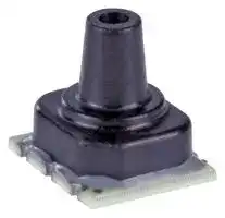


ABPLLNT010BGAA5
Pressure Sensor, Medical, 10 bar, Analogue, Gauge, 5 VDC, Single Axial Barbless, 2.7 mA
- Manufacturer: HONEYWELL
- Product type: Pressure Transducers
- Port Style: Single Axial Barbless
- Product Range: ABP Series
- Sensor Output: Analogue
- Supply Current: 2.7mA
- Voltage Rating: 5VDC
- Operating Pressure Max: 10bar
- Pressure Measurement Type: Gauge
| Delivery and price | |
|---|---|
| Units per pack | 50 |
| Price | 9.38 € |
| Current stock | 10+ |
| Lead time | 30 days |
Basic Board Mount Pressure Sensors **ABP Series—High Accuracy Digital or Analog Output Compensated/Amplified**

60 mbar to 10 bar | 6 kPa to 1 MPa | 1 psi to 150 psi

Datasheet

## Basic Amplified Board Mount Pressure Sensors

The Basic Amplified ABP Series is a piezoresistive silicon pressure sensor offering a ratiometric analog or digital output for reading pressure over the specified full scale pressure span and temperature range.

The ABP Series is fully calibrated and temperature compensated for sensor offset, sensitivity, temperature effects and accuracy errors (which include non-linearity, repeatability and hysteresis) using an on-board Application Specific Integrated Circuit (ASIC). Calibrated output values for pressure are updated at approximately 1 kHz for analog and 2 kHz for digital.

The ABP Series is calibrated over the temperature range of 0 °C to 50 °C [32 °F to 122 °F]. The sensor is characterized for operation from a single power supply of either 3.3 Vdc or 5.0 Vdc. These sensors measure gage and differential pressures.

The Basic Amplified pressure sensors are intended for use with non-corrosive, non-ionic gases, such as air and other dry gases. The following options extend the performance of these sensors to non-corrosive liquids.

- No silicone gel coating: The input port is limited to non-corrosive, non-ionic media such as dry air and gases and should not be exposed to condensation. The gases are limited to media that are compatible with high temperature polyamide, silicone, alumina ceramic, silicon, gold, and glass.

- Silicone gel coating: Uses the same materials in the wetted media path but is protected from condensation by a siliconebased gel coating; allows use in applications where condensation may occur.

All products are designed and manufactured according to ISO 9001 standards.

## Features

- Proprietary Honeywell technology

- Protected by multiple global patents

- Industry-leading long-term stability: ±0.25 %FSS

- Total Error Band (TEB): ±1.5 %FSS

- Industry-leading accuracy: ±0.25 %FSS BFSL

- High burst pressures

- Industry-leading flexibility

- Wide pressure range: 60 mbar to 10 bar | 6 kPa to 1 MPa | 1 psi to 150 psi

- Meets IPC/JEDEC J-STD-020D.1 Moisture Sensitivity Level 1 requirements

- Optional internal diagnostic functions

- Energy efficient

- Output: ratiometric analog; I[2] C- or SPI-compatible 14-bit digital output (min. 12-bit sensor resolution)

- Small size: As small as 8 mm x 7 mm

## Potential Applications **MEDICAL**

   - CPAP

   - Blood analysis

   - Blood pressure monitoring

   - Breast pumps

   - Drug dosing

   - Hospital beds

   - Massage machines

   - Oxygen concentrators

   - Patient monitoring

   - Sleep apnea equipment

   - Urine analyzers

   - Ventilators/portable ventilators

   - Wound therapy

- REACH and RoHS compliant

- Sleep mode option (see Technical Note)

- Temperature output option

- Liquid media option

## **INDUSTRIAL**

- Air brakes

- HVAC/transmitters

- Life sciences

- Material handling

,

## Table of Contents

**==> picture [185 x 151] intentionally omitted <==**

**----- Start of picture text -----**<br>
|||
|---|---|
|General Specifications  .  .  .  .  .  .  .  .  .  .  .  .  .  .  .  .  .  .  . 3|
|Operating Specifications   .  .  .  .  .  .  .  .  .  .  .  .  .  .  .  .  . 4|
|Transfer Function Limits  .  .  .  .  .  .  .  .  .  .  .  .  .  .  .  .  .  . 5|
|Nomenclature and Order Guide  .  .  .  .  .  .  .  .  .  .  .  . 6|
|Pressure Range Specifications   .  .  .  .  .  .  .  .  .  .|7-8|
|PCB Layouts  .  .  .  .  .  .  .  .  .  .  .  .  .  .  .  .  .  .  .  .  .  .  .  .  .  .  . 8|
|Dimensional Drawings:|
|DIP Packages  .  .  .  .  .  .  .  .  .  .  .  .  .  .  .  .  .  .  .  .  .|9-10|
|SMT Packages   .  .  .  .  .  .  .  .  .  .  .  .  .  .  .  .  .  .  .  .11-12|
|Leadless SMT Packages  .  .  .  .  .  .  .  .  .  .  .  .  .  .  . 13|
|Additional Information .  .  .  .  .  .  .  .  .  .  .  . back page|

**----- End of picture text -----**<br>


- Pneumatic control

- Pneumatic regulator

- Process gas monitoring

- Valve positioning and positioners

## **COMMERCIAL**

- Air beds

- Coffee makers

- Washing machines

STABILITY • ACCURACY • FLEXIBILITY • SMALL SIZE

**2** sensing.honeywell.com

## General Specifications

**Table 1. Absolute Maximum Ratings[1]**

**==> picture [543 x 178] intentionally omitted <==**

**----- Start of picture text -----**<br>
Characteristic Min. Max. Unit<br>Supply voltage (Vsupply) -0.3 6.0 Vdc<br>Voltage on any pin -0.3 Vsupply + 0.3 V<br>Digital interface clock frequency:<br>   I [2] C 100 400 kHz<br>   SPI 50 800<br>ESD susceptibility (human body model) 2 — kV<br>Storage temperature -40 [-40] 85 [185] °C [°F]<br>Soldering time and temperature:<br>   lead solder temperature (DIP) 4 s max. at 250 °C [482 °F]<br>   peak reflow temperature (Leadless SMT, SMT) 15 s max. at 250 °C [482 °F]<br>**----- End of picture text -----**<br>


1Absolute maximum ratings are the extreme limits the device will withstand without damage.

**Table 2. Environmental Specifications**

**==> picture [542 x 122] intentionally omitted <==**

**----- Start of picture text -----**<br>
Characteristic Parameter<br>Humidity (Gases only; see “Options N and D” in Figure 2.) 0% to 95% RH, non-condensing<br>Vibration 15 g, 10 Hz to 2 kHz<br>Shock 100 g, 6 ms duration<br>Life [1] 1 million pressure cycles minimum<br>J-STD-020-D.1 Moisture Sensitivity Level 1<br>Solder reflow<br>(unlimited shelf life when stored at <30 °C/85 % RH)<br>**----- End of picture text -----**<br>


- 1Life may vary depending on specific application in which the sensor is used.

**Table 3. Wetted Materials[1]**

**==> picture [543 x 112] intentionally omitted <==**

**----- Start of picture text -----**<br>
Component Pressure Port<br>No SIlicone Gel Coating Option Silicone Gel Coating Option<br>Ports and covers high temperature polyamide<br>Substrate alumina ceramic NOTnot exposed; protected by silicone gel<br>Adhesives epoxy, silicone epoxy<br>Electronic components ceramic, silicon, glass, solder, gold not exposed; protected by silicone gel<br>**----- End of picture text -----**<br>


- 1Contact Honeywell Customer Service for detailed material information.

**Table 4. Sensor Pressure Types**

**==> picture [543 x 56] intentionally omitted <==**

**----- Start of picture text -----**<br>
Pressure Type Description<br>Gage Output is proportional to the difference between applied pressure and atmospheric (ambient) pressure.<br>Differential Output is proportional to the difference between the pressures applied to each port (Port 1 – Port 2).<br>**----- End of picture text -----**<br>


**3**

sensing.honeywell.com

Operating Specifications

**Table 5. Operating Specifications**

**==> picture [542 x 384] intentionally omitted <==**

**----- Start of picture text -----**<br>
Analog Digital<br>Characteristic Unit<br>Min.  Typ. Max. Min.  Typ. Max.<br>Supply voltage (Vsupply): [1, 2, 3]<br>   3.3 Vdc 3.0 3.3 3.6 3.0 3.3 3.6 Vdc<br>   5.0 Vdc 4.75 5.0 5.25 4.75 5.0 5.25<br>Supply current:<br>   3.3 Vdc — 2.1 2.8 — 3.1 3.9 mA<br>   5.0 Vdc — 2.7 3.8 — 3.7 4.6 mA<br>   sleep mode option — — — — 1 10 µA<br>— —<br>Operating temperature range [4] -40 [-40] 85 [185] -40 [-40] 85 [185] °C [°F]<br>— —<br>Compensated temperature range [5] 0 [-32] 50 [122] 0 [-32] 50 [122] °C [°F]<br>Temperature output option [6] — — — — 1.5 — °C<br>Startup time (power up to data ready) — — 5 — — 3 ms<br>Response time — 1 — — 0.46 — ms<br>Clipping limit:<br>   upper — — 97.5 — — — %Vsupply<br>   lower 2.5 — — — — —<br>SPI/I [2] C voltage level:<br>   low — — — — — 20 %Vsupply<br>   high — — — 80 — —<br>Pull up on SDA/MISO, SCL/SCLK, SS — — — 1 — — kOhm<br>Accuracy [7] — — ±0.25 — — ±0.25 %FSS BFSL [8]<br>0.03 — — — — — %FSS<br>Output resolution  — — — 12 — — bits<br>**----- End of picture text -----**<br>


1Sensors are either 3.3 Vdc or 5.0 Vdc based on the catalog listing selected.

2Ratiometricity of the sensor (the ability of the device output to scale to the supply voltage) is achieved within the specified operating voltage.

3The sensor is not reverse polarity protected. Incorrect application of supply voltage or ground to the wrong pin may cause electrical failure.

4Operating temperature range: The temperature range over which the sensor will produce an output proportional to pressure.

5Compensated temperature range: The temperature range over which the sensor will produce an output proportional to pressure within the specified performance limits.

6Temperature Output Option: Continuous operation in Sleep Mode only may provide different results.

7Accuracy: The maximum deviation in output from a Best Fit Straight Line (BFSL) fitted to the output measured over the pressure range at 25 °C [77 °F]. Includes all errors due to pressure non-linearity, pressure hysteresis, and non-repeatability.

8Full Scale Span (FSS): The algebraic difference between the output signal measured at the maximum (Pmax.) and minimum (Pmin.) limits of the pressure range. (See Figure 3 for ranges.)

**Table 6. Sensor Output at Significant Percentages (Digital Versions Only)**

**==> picture [542 x 128] intentionally omitted <==**

**----- Start of picture text -----**<br>
% Output Digital Counts<br>decimal hex<br>0 0 0x0000<br>10 1638 0x0666<br>50 8192 0x2000<br>90 14746 0x399A<br>100 16383 0x3FFF<br>**----- End of picture text -----**<br>


**4** sensing.honeywell.com

## Transfer Function Limits

**Figure 1.Temperature Output Option Temperature Error[1, 2]**

**==> picture [543 x 622] intentionally omitted <==**

**----- Start of picture text -----**<br>
2.5<br>1.5<br>0<br>-1.5<br>-2.5<br>-40 0  25 50 85<br>Temperature (°C)<br>1Operating temperature range: The temperature range over which the sensor will produce an output proportional to pressure.<br>2Compensated temperature range: The temperature range over which the sensor will produce an output proportional to pressure within the specified<br>performance limits.<br>Figure 2. Transfer Function Limits [1]<br>Analog Versions<br>Compensated Pressure Range<br>100<br>90<br>80<br>70<br>60 Ideal<br>50<br>1.5% Total Error Band<br>40<br>30<br>20<br>10<br>0<br>0 1 2 3 4 5 6 7 8 9 10<br>Pmin. Pmax.<br>Pressure (example unit)<br>0.8 x Vsupply<br>Output (V) =  Pmax. – Pmin. x (Pressureapplied – Pmin.) + 0.10 x Vsupply<br>Digital Versions<br>Compensated Pressure Range<br>100<br>90<br>80<br>70<br>60 Ideal<br>50<br>1.5% Total Error Band<br>40<br>30<br>20<br>10<br>0<br>0 1 2 3 4 5 6 7 8 9 10<br>Pmin. Pmax.<br>Pressure (example unit)<br>80%<br>Output (% of 2 [14]  counts) = Pmax. – Pmin. x (Pressureapplied – Pmin.) + 10%<br>Error (°C)<br>Output (%Vsupply)<br> counts)<br>14<br>Output (% of 2<br>**----- End of picture text -----**<br>


1Transfer Function “A” is shown. See Figure 3 for other available transfer function options.

**5**

sensing.honeywell.com

## Nomenclature and Order Guide

## **Figure 3. Nomenclature and Order Guide**

For example, **ABPDNNN150PGAA3** defines an ABP Series Amplified Basic Pressure Sensor, DIP package, NN pressure port, dry gases only, no diagnostics,150 psi gage pressure range, analog output type, 10% to 90% of Vsupply (analog), 2[14] counts (digital) transfer function, no temperature output, no sleep mode, 3.3 Vdc supply voltage.

|**Product Series**<br>**Package**<br>**Pressure Port**<br>DIP<br>**ABP  **Amplified Basic<br>**Option**<br>SMT<br>**NN**<br>Leadless SMT<br>**AN**<br>**LN**<br>Single axial<br>barbed port<br>Single axial<br>barbless port<br>No port<br>**NN**<br>**AN**<br>**LN**<br>Single axial<br>barbed port<br>Single axial<br>barbless port<br>No port<br>**NN**<br>**AN**<br>**LN**<br>Single axial<br>barbed port<br>Single axial<br>barbless port<br>No port<br>**D** DIP (Dual Inline Pin)<br>**M**SMT (Surface Mount Technology)<br>**L** Leadless SMT<br>**Output Type**<br>**Supply Voltage**<br>**Pressure Range2, 3**<br>**3** 3.3 Vdc<br>**5  **5.0 Vdc<br>1The transfer function limits define the output of the sensor at a given  pressure input.<br>By specifying Pmin. and Pmax., the output at Pmin. and Pmax., the complete transfer<br>function of the sensor is defined. See the graphical representations of the transfer<br>function in Figure 2 of the product datasheet.<br>2Custom pressure ranges are available. Contact Honeywell Customer Service for more<br>information.<br>3See the explanation of sensor pressure types in Table 4 of the product datasheet.<br>1 psi to 150 psi<br>60 mbar to 10 bar<br>_Differential_<br>_Differential_<br>_Gage_<br>**001PD**<br>**005PD**<br>**015PD**<br>**030PD**<br>**060PD**<br>_Gage_<br>**001PG**<br>**005PG**<br>**015PG**<br>**030PG**<br>**060PG**<br>**100PG**<br>**150PG**<br>**060MD**<br>**100MD**<br>**160MD**<br>**250MD**<br>**400MD**<br>**600MD**<br>**001BD**<br>**1.6BD**<br>**2.5BD**<br>**004BD**<br>**060MG**<br>**100MG**<br>**160MG**<br>**250MG**<br>**400MG**<br>**600MG**<br>**001BG**<br>**1.6BG**<br>**2.5BG**<br>**004BG**<br>**006BG**<br>**010BG**<br>±60 mbar<br>±100 mbar<br>±160 mbar<br>±250 mbar<br>±400 mbar<br>±600 mbar<br>±1 bar<br>±1.6 bar<br>±2.5 bar<br>±4 bar<br>0 mbar to 60 mbar<br>0 mbar to 100 mbar<br>0 mbar to 160 mbar<br>0 mbar to 250 mbar<br>0 bar to 400 mbar<br>0 bar to 600 mbar<br>0 bar to 1 bar<br>0 bar to 1.6 bar<br>0 bar to 2.5 bar<br>0 bar to 4 bar<br>0 bar to 6 bar<br>0 bar to 10 bar<br>6 kPa to 1 MPa<br>_Differential_<br>_Gage_<br>**006KD**<br>**010KD**<br>**016KD**<br>**025KD**<br>**040KD**<br>**060KD**<br>**100KD**<br>**160KD**<br>**250KD**<br>**400KD**<br>**006KG**<br>**010KG**<br>**016KG**<br>**025KG**<br>**040KG**<br>**060KG**<br>**100KG**<br>**160KG**<br>**250KG**<br>**400KG**<br>**600KG**<br>**001GG**<br>±6 kPa<br>±10 kPa<br>±16 kPa<br>±25 kPa<br>±40 kPa<br>±60 kPa<br>±100 kPa<br>±160 kPa<br>±250 kPa<br>±400 kPa<br>0 kPa to 6 kPa<br>0 kPa to 10 kPa<br>0 kPa to 16 kPa<br>0 kPa to 25 kPa<br>0 kPa to 40 kPa<br>0 kPa to 60 kPa<br>0 kPa to 100 kPa<br>0 kPa to 160 kPa<br>0 kPa to 250 kPa<br>0 kPa to 400 kPa<br>0 kPa to 600 kPa<br>0 kPa to 1 MPa<br>0 psi to 1 psi<br>0 psi to 5 psi<br>0 psi to 15 psi<br>0 psi to 30 psi<br>0 psi to 60 psi<br>0 psi to 100 psi<br>0 psi to 150 psi<br>±1 psi<br>±5 psi<br>±15 psi<br>±30 psi<br>±60 psi<br>**Transfer Function1**<br>**A** 10% to 90% of Vsupply (analog), 214counts (digital)<br>no temperature output, no sleep mode<br>**A**<br>**S**<br>**0**<br>**1**<br>**2**<br>**3**<br>Analog<br>SPI<br>I2C, Address 0x08<br>I2C, Address 0x18<br>I2C, Address 0x28<br>I2C, Address 0x38<br>**N** Dry gases only, no diagnostics<br>Dry gases only, diagnostics on<br>**D**<br>**D**<br>**S** 10% to 90% of 214counts (digital only)<br>no temperature output, sleep mode enabled<br>**4**<br>**5**<br>**6**<br>**7**<br>**8**<br>**9**<br>I2C, Address 0x48<br>I2C, Address 0x58<br>I2C, Address 0x68<br>I2C, Address 0x78<br>I2C, Address 0x88<br>I2C, Address 0x98<br>ABPLLND060MGAA3<br>ABPLLNN600MGAA3<br>ABPMANN005PGAA3<br>ABPMANN004BGAA5<br>ABPMLNN001PGAA3<br>ABPMANN030PG2A3<br>**COMMON CATALOG LISTINGS**<br>**JN**<br>Single radial<br>barbless port<br>**JN**<br>Single radial<br>barbless port<br>**JJ**<br>Dual radial<br>barbless ports,<br>same side<br>**JJ**<br>Dual radial<br>barbless ports,<br>same side<br>**RN** Single radial<br>barbed port<br>**RN** Single radial<br>barbed port<br>**RR**<br>Dual radial<br>barbed ports,<br>same side<br>**RR** Dual radial<br>barbed ports,<br>same side<br>10% to 90% of 214counts (digital only)<br>temperature output enabled, sleep mode enabled<br>ABPMAND001PG2A3<br>ABPLANN001PG2A5<br>ABPDANT005PGAA5<br>ABPDANT015PGAA5<br>ABPLLNT010BGAA5<br>ABPDJJT001PGAA5<br>**T** 10% to 90% of 214counts (digital only)<br>temperature output enabled, no sleep mode<br>Zz,<br>Sp<br>Oo<br>Pp<br>i.<br>~<br>iw, ~<br>i<br>N<br>—esE<br>©<br>a<br>—<br>©<br>w~<br>;<br>yyy)<br>$e<br>SNEF<br>NiS<br>al<br>YZ<br>——<br>=<br>_2<br>=<br>er;>"<br>CSAP<br>—<br>Ci Ss5<br>Gee,<br>W<br>his 4<br>Shy<br>eS<br>Gee,<br>7<br>WY<br>6<br>SRZ<br>it|**Output Type**<br>**Supply Voltage**<br>**3** 3.3 Vdc<br>**5  **5.0 Vdc<br>**Transfer Function1**<br>**A** 10% to 90% of Vsupply (analog), 214counts (digital)<br>no temperature output, no sleep mode<br>**A**<br>**S**<br>**0**<br>Analog<br>SPI<br>I2C, Address 0x08<br>**D**<br>**S** 10% to 90% of 214counts (digital only)<br>no temperature output, sleep mode enabled<br>**4**<br>**5**<br>**6**<br>I2C, Address 0x48<br>I2C, Address 0x58<br>I2C, Address 0x68<br>10% to 90% of 214counts (digital only)<br>temperature output enabled, sleep mode enabled<br>**T** 10% to 90% of 214counts (digital only)<br>temperature output enabled, no sleep mode<br>Oo|**Supply Voltage**<br>**3** 3.3 Vdc<br>**5  **5.0 Vdc<br>**Transfer Function1**<br>**A** 10% to 90% of Vsupply (analog), 214counts (digital)<br>no temperature output, no sleep mode<br>**D**<br>10% to 90% of 214counts (digital only)<br>temperature output enabled, sleep mode enabled|**Supply Voltage**<br>**3** 3.3 Vdc<br>**5  **5.0 Vdc<br>**Transfer Function1**<br>**A** 10% to 90% of Vsupply (analog), 214counts (digital)<br>no temperature output, no sleep mode<br>**D**<br>10% to 90% of 214counts (digital only)<br>temperature output enabled, sleep mode enabled|**Supply Voltage**<br>**3** 3.3 Vdc|**Supply Voltage**<br>**3** 3.3 Vdc|**Supply Voltage**<br>**3** 3.3 Vdc|
|---|---|---|---|---|---|---|
|||||||**5  **5.0 Vdc|
||||**D**<br>10% to 90% of 214counts (digital only)<br>temperature output enabled, sleep mode enabled||||
||||**S** 10% to 90% of 214counts (digital only)<br>no temperature output, sleep mode enabled||||
||||**T** 10% to 90% of 214counts (digital only)<br>temperature output enabled, no sleep mode||||
||||||**S**<br>SPI<br>**5**<br>I2C, Address 0x58<br>Oo||
||||||**0**<br>I2C, Address 0x08<br>**6**<br>I2C, Address 0x68||
||||||**1**<br>I2C, Address 0x18<br>**7**<br>I2C, Address 0x78||
||||||**2**<br>I2C, Address 0x28<br>**8**<br>I2C, Address 0x88||
||||||**3**<br>I2C, Address 0x38<br>**9**<br>I2C, Address 0x98||
|Dry gases only, diagnostics on<br>**D**|||||||


**6**

sensing.honeywell.com

Pressure Range Specifications

**Table 7.  Pressure Range Specifications**

**==> picture [542 x 577] intentionally omitted <==**

**----- Start of picture text -----**<br>
Pressure<br>Pressure  Range Common Mode  Total Error Band [4] Long-term Stability<br>Range Unit Overpressure [1] Burst Pressure [2] 1000 hr, 25 °C<br>Pressure [3] (%FSS)<br> (see Figure 3) Pmin. Pmax. (%FSS)<br>60 mbar to 10 bar<br>Differential<br>060MD -60 60 mbar 850 1000 10000 ±1.5  ±0.25<br>100MD -100 100 mbar 1400 2500 10000 ±1.5 ±0.25<br>160MD -160 160 mbar 1400 2500 10000 ±1.5 ±0.25<br>250MD -250 250 mbar 1400 2500 10000 ±1.5 ±0.25<br>400MD -400 400 mbar 2000 4000 10000 ±1.5 ±0.25<br>600MD -600 600 mbar 2000 4000 10000 ±1.5 ±0.25<br>001BD -1 1 bar 4 8 10 ±1.5 ±0.25<br>1.6BD -1.6 1.6 bar 8 16 10 ±1.5 ±0.25<br>2.5BD -2.5 2.5 bar 8 16 10 ±1.5 ±0.25<br>004BD -4.0 4.0 bar 16 17 10 ±1.5 ±0.25<br>Gage<br>060MG 0 60 mbar 850 1000 5450 ±1.5 ±0.25<br>100MG 0 100 mbar 850 1000 10000 ±1.5 ±0.25<br>160MG 0 160 mbar 850 1000 10000 ±1.5 ±0.25<br>250MG 0 250 mbar 1400 2500 10000 ±1.5 ±0.25<br>400MG 0 400 mbar 2000 4000 10000 ±1.5 ±0.25<br>600MG 0 600 mbar 2000 4000 10000 ±1.5 ±0.25<br>001BG 0 1 bar 2 4 10 ±1.5 ±0.25<br>1.6BG 0 1.6 bar 4 8 10 ±1.5 ±0.25<br>2.5BG 0 2.5 bar 8 16 10 ±1.5 ±0.25<br>004BG 0 4 bar 8 16 16 ±1.5 ±0.25<br>006BG 0 6 bar 17 17 17 ±1.5 ±0.25<br>010BG 0 10 bar 17 17 17 ±1.5 ±0.25<br>6 kPa to 1 MPa<br>Differential<br>006KD -6 6 kPa 85 100 1000 ±1.5  ±0.25<br>010KD -10 10 kPa 140 250 1000 ±1.5 ±0.25<br>016KD -16 16 kPa 140 250 1000 ±1.5 ±0.25<br>025KD -25 25 kPa 140 250 1000 ±1.5 ±0.25<br>040KD -40 40 kPa 200 400 1000 ±1.5 ±0.25<br>060KD -60 60 kPa 200 400 1000 ±1.5 ±0.25<br>100KD -100 100 kPa 400 800 1000 ±1.5 ±0.25<br>160KD -160 160 kPa 800 1600 1000 ±1.5 ±0.25<br>250KD -250 250 kPa 800 1600 1000 ±1.5 ±0.25<br>400KD -400 400 kPa 1600 1700 1000 ±1.5 ±0.25<br>Gage<br>006KG 0 6 kPa 85 100 545 ±1.5 ±0.25<br>010KG 0 10 kPa 85 100 1000 ±1.5 ±0.25<br>016KG 0 16 kPa 85 100 1000 ±1.5 ±0.25<br>025KG 0 25 kPa 140 250 1000 ±1.5 ±0.25<br>040KG 0 40 kPa 200 400 1000 ±1.5 ±0.25<br>060KG 0 60 kPa 200 400 1000 ±1.5 ±0.25<br>100KG 0 100 kPa 200 400 1000 ±1.5 ±0.25<br>160KG 0 160 kPa 400 800 1000 ±1.5 ±0.25<br>250KG 0 250 kPa 800 1600 1000 ±1.5 ±0.25<br>400KG 0 400 kPa 800 1600 1600 ±1.5 ±0.25<br>600KG 0 600 kPa 1700 1700 1700 ±1.5 ±0.25<br>001GG 0 1 MPa 1.7 1.7 1.7 ±1.5 ±0.25<br>**----- End of picture text -----**<br>


1Overpressure: The maximum pressure which may safely be applied to the product for it to remain in specification once pressure is returned to the operating pressure range. Exposure to higher pressures may cause permanent damage to the product. Unless otherwise specified this applies to all available pressure ports at any temperature with the operating temperature range.

> 2Burst pressure: The maximum pressure that may be applied to any port of the product without causing escape of pressure media. Product should not be expected to function after exposure to any pressure beyond the burst pressure.

3Common mode pressure: The maximum pressure that can be applied simultaneously to both ports of a differential pressure sensor without causing changes in specified performance.

- 4Total Error Band: The maximum deviation from the ideal transfer function over the entire compensated temperature and pressure range. Includes all errors due to offset, full scale span, pressure non-linearity, pressure hysteresis, repeatability, thermal effect on offset, thermal effect on span, and thermal hysteresis.

**7**

sensing.honeywell.com

## Pressure Range Specifications

## PCB Pad Layouts

**Table 7. Pressure Range Specifications (continued)**

**==> picture [542 x 201] intentionally omitted <==**

**----- Start of picture text -----**<br>
Pressure<br>Pressure  Long-term Stability<br>Range Range Unit Overpressure [1] Burst Pressure [2] Common Mode  Total Error Band [4] 1000 hr, 25 °C<br>Pressure [3] (%FSS)<br> (see Figure 3) Pmin. Pmax. (%FSS)<br>1 psi to 150 psi<br>Differential<br>001PD -1 1 psi 10 15 150 ±1.5% ±0.25%<br>005PD -5 5 psi 30 40 150 ±1.5% ±0.25%<br>015PD -15 15 psi 60 120 150 ±1.5% ±0.25%<br>030PD -30 30 psi 120 240 150 ±1.5% ±0.25%<br>060PD -60 60 psi 250 250 250 ±1.5% ±0.25%<br>Gage<br>001PG 0 1 psi 10 15 150 ±1.5% ±0.25%<br>005PG 0 5 psi 30 40 150 ±1.5% ±0.25%<br>015PG 0 15 psi 30 60 150 ±1.5% ±0.25%<br>030PG 0 30 psi 60 120 150 ±1.5% ±0.25%<br>060PG 0 60 psi 120 240 250 ±1.5% ±0.25%<br>100PG 0 100 psi 250 250 250 ±1.5% ±0.25%<br>150PG 0 150 psi 250 250 250 ±1.5% ±0.25%<br>**----- End of picture text -----**<br>


1Overpressure: The maximum pressure which may safely be applied to the product for it to remain in specification once pressure is returned to the operating pressure range. Exposure to higher pressures may cause permanent damage to the product. Unless otherwise specified this applies to all available pressure ports at any temperature with the operating temperature range.

> 2Burst pressure: The maximum pressure that may be applied to any port of the product without causing escape of pressure media. Product should not be expected to function after exposure to any pressure beyond the burst pressure.

3Common mode pressure: The maximum pressure that can be applied simultaneously to both ports of a differential pressure sensor without causing changes in specified performance.

4Total Error Band: The maximum deviation from the ideal transfer function over the entire compensated temperature and pressure range. Includes all errors due to offset, full scale span, pressure non-linearity, pressure hysteresis, repeatability, thermal effect on offset, thermal effect on span, and thermal hysteresis.

## **Table 8. Pinouts**

**==> picture [542 x 57] intentionally omitted <==**

**----- Start of picture text -----**<br>
Output Type Pin 1 Pin 2 Pin 3 Pin 4 Pin 5 Pin 6<br>Digital (I [2] C, SPI) GND VDD SS/INT NC SDA SCL<br>Analog GND NC Vout NC NC VDD<br>**----- End of picture text -----**<br>


**Figure 4. Recommended PCB Layouts**

**==> picture [543 x 222] intentionally omitted <==**

**----- Start of picture text -----**<br>
DIP SMT Leadless SMT<br>Gage reference hole: do not plug Gage reference hole: do not plug Gage reference hole: do not plug<br>1 2 3           [0.029]6X ø0.73 [0.026]0,65 [0.051]1,30<br>1 3<br>[0.236]6,00 [0.236]6,00 [0.348]8,85 [0.157]4,00 1 2 3 3,25 [0.28]7,00<br>0.128] 8,00<br>11,25 11,0 [0.433]11,00 3,00 6 5 4 [0.315]<br>[0.443] [0.433] [0.118]<br>12,35<br>5,00 5,00 [0.315]<br>[0.197] [0.197]<br>6 5 4 2,73 2,50<br>[0.107] [0.098]<br>6 5 4 8,00<br>[0.315]<br>2,73 2,54 2,73 2,54<br>[0.107] [0.1] [0.107] [0.1]<br>8,00 8,00<br>[0.315] [0.315]<br>2<br>**----- End of picture text -----**<br>


**8** sensing.honeywell.com

## Dimensional Drawings DIP Packages

## **Figure 5. DIP Package Dimensional Drawings (For reference only: mm [in].)**

**DIP NN:** No port

**DIP AN:** Single axial barbed port

**==> picture [379 x 288] intentionally omitted <==**

**----- Start of picture text -----**<br>
7,3                  3,23 Wet media<br>[0.29] [0.127] 8,0<br>4,0                  2,95 Dry media [0.32]<br>[0.16] [0.116]         2,54 Typ. t—         2X 1,45<br>4 5 6 [0.100] 6 5 4             [0.057]<br>5,5<br>[0.22]<br>[0.25]6,3 [0.45]11,5 [0.43]11,0<br>3 2 1 1,0 1 2 3<br>lial ial al [0.04] [0.34]8,6 st         0,25 Typ. [0.010] Ld      [0.018]6X 0,46<br>7,3<br>4,0 [0.29] [0.276]7,00                   3,63 Wet media[0.143] [0.32]8,0<br>[0.16]                  3,35 Dry media         2,54 Typ.         2X 1,45<br>4 5 6 3,56 [0.131] [0.100] 6 5 4              [0.057]<br>[0.140]<br> ø1,91<br>5,5     [0.075]<br>[0.22]<br>6,3  ø2,74 11,5<br>[0.25]    [0.108] [0.45] 11,0<br>[0.43]<br> ø2,32 on<br>    [0.091]<br>fel el ap<br>| hid te a!  —_—— He<br>3 2 1 1,0 1 2 3<br>[0.04] [0.34]8,6         0,25 Typ.[0.010]      [0.018]6X 0.46<br>**----- End of picture text -----**<br>


**DIP LN:** Single axial barbless port

**==> picture [533 x 289] intentionally omitted <==**

**----- Start of picture text -----**<br>
                 3,23 Wet media<br>7,3 [0.127] 8,0<br>4,0 — [0.29]                  2,95 Dry media         2,54 Typ. Z [0.32]         2X 1,45<br>[0.16] 4 5 6 [0.116] [0.100] 6 5 4             [0.057]<br>4,80<br>[0.189]<br>5,5<br>[0.22]<br>[0.25]6,3     [0.197] ø5,00 [0.45]11,5 [0.43]11,0<br>2,68<br>[0.106]<br>liealiealival 3 2 1 1,0 —_         0,25 Typ. al mud 1 2 3<br>[0.04] 8,6 [0.010] 6X 0.46<br>[0.34]      [0.018]<br>DIP JN:  Single radial<br>barbless port                  3,38 Wet media<br>[0.133]<br>8,0 4,65 2,16<br>4         5         6                  3,10 Dry media[0.122]         0,25 Typ. [0.010] 6          5          4[0.32] [0.183] [0.085]<br>4,45<br>[0.175]<br>6,3<br> ø1,88 [0.25] [0.45]11,5 [0.43]11,0<br>    [0.074]<br>ea Ces<br>if | PITA 3          2          1 1,0 | 2X 1,45 | HHH 1         2          3 6X 0,46<br>7,3 [0.04] 8,6       [0.057]       [0.018]<br>| [0.29] [0.34] a Te         2,54 Typ.<br> [0.100]<br>**----- End of picture text -----**<br>


**9**

sensing.honeywell.com

## Dimensional Drawings

## DIP Packages

## **Figure 5. DIP Package Dimensional Drawings (continued)**

**DIP JJ:** Dual radial barbless ports, same side

**==> picture [513 x 209] intentionally omitted <==**

**----- Start of picture text -----**<br>
                 3,38 Wet media<br>[0.133]<br>8,0<br>                 3,10 Dry media [0.32]<br>2X 4,0 [0.122]         2,54 Typ. 2X 1,47<br>     [0.16] 2,08  [0.100]       [0.058]<br>7 4         5         6 [0.082] - 6          5         4 2X 4,65<br>2,10       [0.183]<br>[0.083] 4,45 2X ø1,88<br>Port 1 [0.175]          [0.074]<br>b | [PS|PSIPS|a_ [0.25]6,3 Port 1 Port 2 ) [0.45]11,5 [0.43]11,0 (poa , oh<br>Port 2 4,45<br>[0.175]<br>3         2          1[0.29]7,3 [0.04]1,0 8,6        0,25 Typ.[0.010]      [0.018]6X 0,46 1         2         3                 5,06 ±0,3 Wet media[0.199 ±0.012]<br>[0.34]<br>                 4,78 ±0,3 Dry media<br>[0.188 ±0.012]<br>DIP RN:  Single radial<br>barbed port<br>**----- End of picture text -----**<br>


**==> picture [515 x 339] intentionally omitted <==**

**----- Start of picture text -----**<br>
                 3,58 Wet media<br>[0.141] 8,0<br>   [0.063] ø1,60 7 [0.16]4,04         5          6                  3,30 Dry media[0.1296]         2,54 Typ. [0.100] — 6          5          4[0.32]      [0.058]2X 1,47 [0.079]2,01<br>3,10<br>[0.122] 4,55<br>[0.179]<br>Gi y PS  ø1,75 | [0.25]6,3 [0.45]11,5 [0.43]11,0 ==<br>    [0.069]<br>Pe a ae<br> ø2,10<br>    [0.083]<br>3          2          1[0.29]7,3        0,25 Typ.[0.010]8,6      [0.018]6X 0,46 1          2          3 [0.187]4,75 [0.065]1,65<br>[0.34] a<br> Dual radial barbed<br>ports, same side<br>                 3,58 Wet media<br>[0.141] 8,0<br>                 3,30 Dry media         2,54 Typ. _ [0.32]<br>2X 4,0 [0.129]  [0.100] 2X 4,75<br>     [0.16] 2,28 2X 1,45      [0.187]<br>4         5          6 [0.090]          [0.057] 6          5          4<br>1,90 2X ø1,75<br>[0.075] 4,55          [0.069]<br>Port 1 Port 1 [0.179] 2X ø1,60<br>         [0.063]<br>6,3 Port 2 11,5<br>[0.25] [0.45] 11,0<br>[0.43]<br>Port 2 4,55               [0.083] 2X ø,2,10<br>[0.179]<br>1) : Talila 3          2          1[0.29]7,3 [0.04]1,0 [0.34]8,6        0,25 Typ. f [0.010] |      [0.018]6X 0,46 1          2          3 _{ply [0.187]4,76<br>**----- End of picture text -----**<br>


**DIP RR:** Dual radial barbed ports, same side

**10**

sensing.honeywell.com

## Dimensional Drawings

## SMT Packages

## **Figure 6. SMT Package Dimensional Drawings (For reference only: mm [in].)**

**==> picture [67 x 9] intentionally omitted <==**

**----- Start of picture text -----**<br>
SMT NN:  No port<br>**----- End of picture text -----**<br>


**==> picture [531 x 624] intentionally omitted <==**

**----- Start of picture text -----**<br>
                 3,23 Wet media<br>7,3 [0.127]<br>[0.29]<br>4,0 2                  2,95 Dry media 8,0<br>[0.16] [0.116] [0.32]<br>4 5 6 6 5 4<br>5,5<br>[0.22]<br>6,3 11,5 11,0<br>[0.25] [0.45] [0.43]<br>6X1,28<br>     [0.050]<br>3 2 1 1,0 6X 0.46 1 2 3<br>[0.04] 4,2      [0.018]<br>[0.17]         2,54 Typ. 2X 1,45<br>[0.100]      [0.057]<br>SMT AN:  Single axial<br>barbed port 7,3 [0.276]7,00                  3,63 Wet media[0.143]<br>[0.29]                  3,35 Dry media 8,0<br>4,0 [0.131] [0.32]<br>[0.16] 4 5 6         0,25 Typ.[0.010] 6 5 4<br>3,56<br>5,5 [0.140]<br>[0.22]<br>[0.25]6,3     [0.108] ø2,74 [0.45]11,5 [0.43]11,0<br>6X 1.28<br> ø2,32      [0.050]<br>    [0.091]<br> ø1,91<br>    [0.075]<br>: 3 2 1 [0.04]1,0 6X 0.46 1 2 3<br>4,2      [0.018]<br>[0.17]<br>75 eee ESL» aa         2,54 Typ. 2X 1,45<br>[0.100]      [0.057]<br>SMT LN:  Single axial<br>barbless port                  3,23 Wet media<br>7,3 [0.127]<br>[0.29]<br>[0.16]4,0 -                  2,95 Dry media[0.116]         0,25 Typ. [0.32]8,0<br>4 5 6  [0.010] 6 5 4<br>4,80<br>[0.189]<br>5,5<br>[0.22]<br>11,0<br>6,3  ø5,00 11,5 [0.43]<br>[0.25]     [0.197] [0.45]<br>6X 1,28<br>2,68      [0.050]<br>[0.106]<br>3 2 1 1,0 6X 0.46 1 2 3<br>[0.04] 4,2      [0.018]<br>[0.17]         2,54 Typ. 2X 1,45<br>[0.100]      [0.057]<br>SMT JN:  Single radial<br>barbless port                  3,38 Wet media<br>[0.133] 8,0<br>4,0                  3,10 Dry media [0.32]<br>[0.183]4,65 [0.16]4         5         6 [0.122]        0,25 Typ. [0.010]         2,54 Typ. [0.100] roo 6         5         4 [0.058]1,47 [0.085]2,16<br>4,45<br>[0.175]<br>11,0<br>6,3 11,5 [0.43]<br> ø1,88 [0.25] [0.45]<br>   [0.074]<br>3         2         1 1,0 1       2         3<br>[0.29]7,3 [0.04] 4,2      [0.050]6X 1,28 6X 0.46<br>[0.17]      [0.018]<br>        0,25 Typ.<br> [0.010]<br>**----- End of picture text -----**<br>


**11**

sensing.honeywell.com

## Dimensional Drawings SMT Packages

## **Figure 6. SMT Package Dimensional Drawings (continued)**

**==> picture [521 x 239] intentionally omitted <==**

**----- Start of picture text -----**<br>
SMT JJ:  Dual radial<br>barbless ports, same side<br>                 3,38 Wet media<br>[0.133] 8,0<br>                 3,10 Dry media         2,54 Typ. _ [0.32]                  5,06 ±0,3 Wet media<br>2X 4,65 2X 4,0 [0.122]  [0.100] [0.199 ±0.012]<br>     [0.183]      [0.16]4         5        6 [0.082]2,08      [0.057]2X 1,45 6         5         4                 4,78 ±0,3 Dry media[0.188 ±0.012]<br>2,10 4,45 2X ø1,88<br>ot [0.083] Port 1 11,5 [0.175]          [0.074]<br> é [0.25]6,3 Port 1 Port 2 [0.45] [0.43]11,0<br>Port 2         0,25 Typ. [0.010] 4,45<br>[0.175]<br>3        2         1 1,0 1        2        3<br>[0.29]7,3 [0.04] [0.17]4,2      [0.050]6X 1,28 Poe      [0.018]6X 0,46<br>SMT RN:  Single radial<br>barbed port<br>**----- End of picture text -----**<br>


**==> picture [374 x 136] intentionally omitted <==**

**----- Start of picture text -----**<br>
                 3,58 Wet media 8,0<br>[0.141]         2,54 Typ. [0.32]<br>                 3,30 Dry media  [0.100] 2,01<br>4,0 [0.129] 4,75 [0.079]<br>    [0.069] ø1,75 [0.16]4         5         6        0,25 Typ.[0.010]      [0.057]2X 1,45 I} 6         5         4 [0.187]<br> ø1,60<br>   [0.063] 4,55<br>[0.179]<br>[0.25]6,3 [0.45]11,5 [0.43]11,0<br> ø2,10<br>    [0.083] =. haa<br>3         2         1[0.29]7,3 [0.04]1,0 4,2      [0.050]6X 1,28 1         2        3     [0.018]6X 0,46 [0.065]1,65<br>[0.17]<br>**----- End of picture text -----**<br>


**SMT RR:** Dual radial barbed ports, both sides

**==> picture [412 x 127] intentionally omitted <==**

**----- Start of picture text -----**<br>
                 3,58 Wet media 8,0<br>[0.141] [0.32]<br>        2,54 Typ. [—<br>                 3,30 Dry media  [0.100]<br>2X 4,75 2X 4,0 [0.129]<br>[0.122]3,10      [0.187]     [0.16]4         5         6 [0.090]2,28          [0.057]2X 1,45 6         5         4 , [0.187]4,76<br>2X ø1,60<br>[0.075]1,90 Port 1 Port 1 [0.179]4,55          [0.063]<br> 2X ø,2,10<br>6,3 Port 2 11,0                [0.083]<br>[0.25] 11,5 [0.43]<br>Port 2 [0.45] 2X ø1,75 4,55<br>         [0.069] [0.179]<br>Sank<br>3         2         1 1,0 1        2         3<br>[0.29]7,3 [0.04] [0.165]4,20      [0.050]6X 1,28      [0.018]6X 0,46<br>**----- End of picture text -----**<br>


**12** sensing.honeywell.com

## Dimensional Drawings Leadless SMT Packages

## **Figure 7. Leadless SMT Package Dimensional Drawings (For reference only: mm [in].)**

**Leadless SMT AN** : No port

**Leadless SMT AN:** Single axial barbed port

**Leadless SMT AN:** Single axial barbless port

**==> picture [369 x 549] intentionally omitted <==**

**----- Start of picture text -----**<br>
                 3,23 Wet media<br>[0.13]<br>                 2,95 Dry media<br>4,0 [0.12]<br>[0.16]<br>1,0<br>C 1 2 3 A [0.04] 3 2 1<br>3,5<br>[0.14] 6,3 3,00 6X 0,25 [0.28]7,0<br>[0.25] [0.118]      [0.049]<br>a 6 5 4 1,0 TU] 4 5 6 ft<br>7,3 [0.04]       2,5 Typ. 1,5<br>[0.29] [0.10] [0.06]<br>8,0<br>te [0.32]<br>                 3,63 Wet media<br>[0.14]<br>                 3,35 Dry media<br>4,0 [0.13]<br>[0.16]<br>7,0<br>: 1 2 3 [0.28] - 1,0 3 2 1<br>3,56 [0.04]<br>[0.14]3,5 6,3  ø2,74 [0.140] 3,00 6X 0,25 [0.28]7,0<br>[0.25]     [0.108] [0.118]      [0.049]<br> ø2,32<br>6 5 4  ø1,91     [0.091] 4 5 6<br>yay 7,3     [0.075] 1a FLY       2,5 Typ. Ty. 1,5<br>[0.29] [0.10] [0.06]<br>8,0<br>(@) Ta feel [0.32]<br>                 3,23 Wet media<br>[0.13]<br>                 2,95 Dry media<br>4,0 [0.12]<br>[0.16]<br>1 2 3  ø5,0 [0.04]1,0 3 2 1<br>    [0.20]<br>3,5<br>[0.14] 6,3  ø2,68 3,00 6X 0,25 [0.28]7,0<br>[0.25]     [0.106] [0.118]      [0.049]<br>t =I TIT]<br>C° 6 5 4 Ta 4,1 0,7 ait 4 5 6<br>7,3 [0.16] [0.03]       2,5 Typ. nim| 1,5<br>[0.29] [0.10] [0.06]<br>8,0<br>[0.32]<br>**----- End of picture text -----**<br>


**13**

sensing.honeywell.com

## **ADDITIONAL INFORMATION**

The following associated literature is available at sensing.honeywell.com:

- Product Line Guide

- Product Range Guide

- Product Nomenclature Tree

- Installation Instructions

- Application Information

## **WARNING**

## **PERSONAL INJURY**

**DO NOT USE** these products as safety or emergency stop devices or in any other application where failure of the product could result in personal injury.

**Failure to comply with these instructions could result in death or serious injury.**

- Technical Notes:

- I[2] C Communications with Honeywell Digital Output Pressure Sensors

- SPI Communications with Honeywell Digital Output Pressure Sensors

- Sleep Mode with Honeywell Digital Output Pressure Sensors

## **WARNING**

## **MISUSE OF DOCUMENTATION**

- The information presented in this product sheet is for reference only. Do not use this document as a product installation guide.

- Complete installation, operation, and maintenance information is provided in the instructions supplied with each product.

**Failure to comply with these instructions could result in death or serious injury.**

## **WARRANTY/REMEDY**

## **Find out more**

Honeywell serves its customers through a worldwide network of sales offices, representatives and distributors. For application assistance, current specifications, pricing or name of the nearest Authorized Distributor, contact your local sales office.

To learn more about Honeywell’s sensing and control products, call **+1-815-235-6847 or**

Honeywell warrants goods of its manufacture as being free of defective materials and faulty workmanship. Honeywell’s standard product warranty applies unless agreed to otherwise by Honeywell in writing; please refer to your order acknowledgement or consult your local sales office for specific warranty details. If warranted goods are returned to Honeywell during the period of coverage, Honeywell will repair or replace, at its option, without charge those items it finds defective. **The foregoing is buyer’s sole remedy and is in lieu of all other warranties, expressed or implied, including those of merchantability and fitness for a particular purpose. In no event shall Honeywell be liable for consequential, special, or indirect damages.**

While we provide application assistance personally, through our literature and the Honeywell website, it is up to the customer to determine the suitability of the product in the application.

Specifications may change without notice. The information we supply is believed to be accurate and reliable as of this printing. However, we assume no responsibility for its use.

**1-800-537-6945** , visit **sensing.honeywell.com,** or e-mail inquiries to

**info.sc@honeywell.com**

Sensing and Productivity Solutions Honeywell 1985 Douglas Drive North Golden Valley, MN 55422

**honeywell.com**

32305128-C-EN IL50 October 2015 © 2015 Honeywell International Inc. All rights reserved.
Updated at February 9, 2023
Honeywell is a globally recognized leader in the design and manufacture of advanced sensing and switching solutions. Renowned for engineering components that deliver enhanced precision and ruggedness, Honeywell provides essential technologies for demanding applications across critical healthcare, aerospace, and industrial equipment. With a comprehensive portfolio built to address both basic and complex design challenges, the company stands at the forefront of reliable electronic component manufacturing. The core of our Honeywell offering is an extensive selection of high-performance sensors and transducers. This includes a robust lineup of pressure sensors and transducers engineered for accurate fluid and gas measurement in challenging environments. Furthermore, we provide a wide array of temperature sensors and specialized temperature sensing NTC thermistors designed for stable thermal management, alongside precision current sensors and load cells that deliver critical feedback for control systems. Beyond advanced sensing technology, Honeywell’s expertise extends to essential circuit protection and electromechanical components. Our selection encompasses power relays, thermal magnetic circuit breakers, and standard terminal blocks, ensuring safe and efficient power distribution. Whether integrating core components or sourcing specialized accessories, design engineers can rely on Honeywell for uncompromising quality and operational excellence.
About Novapart
Novapart is a B2B electronic component broker specialising in stock shortages and cost reduction. We source hard-to-find parts and identify compliant alternatives across a catalogue of 410,000+ components from 500+ manufacturers.
Learn more →Stock Shortage Specialist
When a component is unavailable, discontinued or has an unacceptable lead time, we tap into our network of vetted European and Asian distributors to source what you need — without compromising on quality or traceability.
Request a quote →Compliant Alternatives
We identify pin-to-pin, electrically equivalent substitutes that meet the same certifications (RoHS, AEC-Q100, REACH) as your original specification — validated against datasheets, not just part numbers. Often at a lower cost.
BOM Analysis service →