
Image not available
Illustrative purposes only

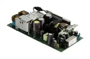
ABC401-1012
AC/DC Open Frame Power Supply (PSU), ITE, 1 Output, 400W @ 400LFM, 250 W, 90V AC to 264V AC
⚠️ Reference pricing provided. In case of supply shortages, we will connect you with our trusted procurement partners to ensure your project's continuity.
- Manufacturer: BEL POWER SOLUTIONS
- Product type: AC / DC Open Frame Power Supplies
- SVHC: To Be Advised
- Product Range: ABC401 Series
- No. of Outputs: 1 Output
- Current, Output 4: -
- Input Voltage VAC: 90V AC to 264V AC
- Power Supply Output Type: Adjustable, Fixed
- Output Current - Output 1: 33.3A
- Output Current - Output 2: -
- Output Current - Output 3: -
- Output Voltage - Output 1: 12VDC
- Output Voltage - Output 2: -
- Output Voltage - Output 3: -
- Output Voltage - Output 4: -
- Power Supply Applications: ITE
- Power Rating (Forced Cooling): 400W @ 400LFM
- Power Rating (Convection Cooling): 250W
| Delivery and price | |
|---|---|
| Units per pack | 5 |
| Price | 116.17 € |
| Current stock | 10+ |
| Lead time | 30 days |
Datasheet

The ABC401 Series of AC-DC power supplies provides up to 400 W of regulated output power through wide input voltage range 90 – 264 VAC in single outputs of 12, 24, 28, 36 or 48 VDC. The ABC401 Series comes in five different low-profile packages, offering 12 and 5 VSB standby outputs and a full set of protection features. Available control signals include Power Good (P_OK), Remote On/Off (PS_ON) and remote sense compensation on the (+) load line. The ABC401 Series complies with the latest international safety standards for IT equipment and displays the CE-Mark for the European Low Voltage Directive (LVD). a - Key Features & Benefits = — • Universal input voltage range (90 – 264 VAC) • Active PFC, EN 61000-3-2 Class C, D compliant • Steady 400 W output power (440 W peak) • High efficiency (94% typical) • Low stand by power consumption (<0.5 W) • 12, 24, 28, 36, 48 VDC standard output voltages • +5V stand by, 2 A and 12 V auxiliary, 1 A outputs • Low earth/touch leakage currents (<300/100 µA) • Fan speed control function (Off at <50 W) • Over temperature protection • Input under voltage, output over voltage protections • Over current and short circuit protection • Remote On/Off and power good signal • 5 available packages all fit 1U installation • UL 60950-1 and 62368-1 compliance • EN 55032, FCC Class B, conducted radiated emissions. • EN 55024 immunity • 4000 m operation without de-rating • RoHS 3 compliant (Directive EU 2015/863) ROHS a ~ Applications • Video Wall Display & Entertainment • Industrial Process Control • Telecommunications • Test & Measurement Equipment • Industrial Laser applications

- 3D Printing and ATM

ABC401 Series

**==> picture [491 x 693] intentionally omitted <==**

**----- Start of picture text -----**<br>
||||||||
|---|---|---|---|---|---|---|
|2|
|MODEL|SELECTION|
|INPUT VOLTAGE|NOM. OUTPUT|MAX. OUTPUT|MAX. OUTPUT|
|MODEL NUMBER|PACKAGE & COOLING|RANGE|VOLTAGE|POWER|CURRENT|DIMENSIONS|
|[VAC]|[VDC]|[W]|[A]|
|ABC401-1012|Open Frame|90 - 264|12|400|33.3|76.0 x 164.2 x 37.7 mm|
|Convection / Forced Air|(2.99 x 6.46 x 1.48 in)|
|U-Chassis|84.4 x 166.5 x 40.0 mm|
|ABC401-1012-UC|90 - 264|12|400|33.3|
|Convection / Forced Air|(3.32 x 6.55 x 1.57 in)|
|Perforated Cover|84.4 x 166.5 x 41.0 mm|
|ABC401-1012-PC|90 - 264|12|400|33.3|
|Convection / Forced Air|(3.32 x 6.55 x 1.61 in)|
|Vented Cover|84.4 x 183.0 x 41.0 mm|
|ABC401-1012-T|90 - 264|12|400|33.3|
|Top Fan|(3.32 x 7.20 x 1.61 in)|
|Enclosed|84.4 x 183.0 x 41.0 mm|
|ABC401-1012-S|90 - 264|12|400|33.3|
|Front Mounted Fan|(3.32 x 7.20 x 1.61 in)|
|ABC401-1024|Open Frame|90 - 264|24|400|16.7|76.0 x 164.2 x 37.7 mm|
|Convection / Forced Air|(2.99 x 6.46 x 1.48 in)|
|U-Chassis|84.4 x 166.5 x 40.0 mm|
|ABC401-1024-UC|90 - 264|24|400|16.7|
|Convection / Forced Air|(3.32 x 6.55 x 1.57 in)|
|Perforated Cover|84.4 x 166.5 x 41.0 mm|
|ABC401-1024-PC|90 - 264|24|400|16.7|
|Convection / Forced Air|(3.32 x 6.55 x 1.61 in)|
|Vented Cover|84.4 x 183.0 x 41.0 mm|
|ABC401-1024-T|90 - 264|24|400|16.7|
|Top Fan|(3.32 x 7.20 x 1.61 in)|
|Enclosed|84.4 x 183.0 x 41.0 mm|
|ABC401-1024-S|90 - 264|24|400|16.7|
|Front Mounted Fan|(3.32 x 7.20 x 1.61 in)|
|U-Chassis|84.4 x 166.5 x 40.0 mm|
|ABC401-1028-UC|90 - 264|28|400|14.3|
|Convection / Forced Air|(3.32 x 6.55 x 1.57 in)|
|ABC401-1036|Open Frame|90 - 264|36|400|11.1|76.0 x 164.2 x 37.7 mm|
|Convection / Forced Air|(2.99 x 6.46 x 1.48 in)|
|U-Chassis|84.4 x 166.5 x 40.0 mm|
|ABC401-1036-UC|90 - 264|36|400|11.1|
|Convection / Forced Air|(3.32 x 6.55 x 1.57 in)|
|Perforated Cover|84.4 x 166.5 x 41.0 mm|
|ABC401-1036-PC|90 - 264|36|400|11.1|
|Convection / Forced Air|(3.32 x 6.55 x 1.61 in)|
|Vented Cover|84.4 x 183.0 x 41.0 mm|
|ABC401-1036-T|90 - 264|36|400|11.1|
|Top Fan|(3.32 x 7.20 x 1.61 in)|
|Enclosed|84.4 x 183.0 x 41.0 mm|
|ABC401-1036-S|90 - 264|36|400|11.1|
|Front Mounted Fan|(3.32 x 7.20 x 1.61 in)|
|ABC401-1048|Open Frame|90 - 264|48|400|8.3|76.0 x 164.2 x 37.7 mm|
|Convection / Forced Air|(2.99 x 6.46 x 1.48 in)|
|U-Chassis|84.4 x 166.5 x 40.0 mm|
|ABC401-1048-UC|90 - 264|48|400|8.3|
|Convection / Forced Air|(3.32 x 6.55 x 1.57 in)|
|Perforated Cover|84.4 x 166.5 x 41.0 mm|
|ABC401-1048-PC|90 - 264|48|400|8.3|
|Convection / Forced Air|(3.32 x 6.55 x 1.61 in)|
|Vented Cover|84.4 x 183.0 x 41.0 mm|
|ABC401-1048-T|90 - 264|48|400|8.3|
|Top Fan|(3.32 x 7.20 x 1.61 in)|
|Enclosed|84.4 x 183.0 x 41.0 mm|
|ABC401-1048-S|90 - 264|48|400|8.3|
|Front Mounted Fan|(3.32 x 7.20 x 1.61 in)|
|see|POWER|
|tage enn|tech.support@psbel.com|||

**----- End of picture text -----**<br>


ABC401 Series

3

|**PARAMETER**|||**DESCRIPTION / CONDITION**|**MIN**|**NOM**|**MAX**|**UNIT**|
|---|---|---|---|---|---|---|---|
|AC Input Voltage|||PS starts and operates at 90 VACat all load conditions|90|100-240|100-240<br>264|VRMS|
|DC Input Voltage||||170|-|270|VDC|
|Input Frequency<br>47<br>50/60<br>440<br>Hz<br>Input Current<br>RMS at 180 VAC, maximum load, 50 / 60 Hz<br>RMS at 90 VAC, maximum load, 50 / 60 Hz<br>-<br>-<br>2.5<br>5.0<br>A<br>Inrush Current<br>265 VAC, 25 °C ambient, cold start.<br>24, 28, 36, 48 V, no damage<br>12 V<br>-<br>-<br>-<br>-<br>-<br>20<br>A<br>Fusing<br>2x Time Lag 6.3 A, 250 V on both L and N<br>-<br>-<br>6.3<br>A<br>Efficiency<br>At 115 VAC<br>20% rated load<br>90<br>-<br>-<br>%<br>50 – 100 % rated load<br>92<br>-<br>-<br>At 230 VAC<br>20% rated load<br>90<br>-<br>-<br>50 – 100 % rated load<br>94<br>-<br>-<br>Input Power Consumption<br>Power on, 115-230 VRMS, no load<br>Stand by, 115-230 VRMS, no load<br>-<br>-<br>1<br>0.4<br>1.5<br>0.5<br>W<br>Power Factor<br>At full rated load, 115 VAC, 60 Hz and 230 VAC, 50 Hz input voltages<br>0.95<br>-<br>-<br>-<br>Harmonic Current<br>Fluctuations and Flicker<br>Complies with EN-61000-3-2 Class C at 230 VAC  50 Hz, load >50 W.<br>Complies with EN-61000-3-3 at nominal voltages and full load.<br>Earth Leakage Current<br>Normal conditions, 240 VRMS, 60 Hz.<br>300<br>µA<br>END OF LIFE||||||||


**Asia-Pacific Europe, Middle East North America** +86 755 298 85888 +353 61 49 8941 +353 61 49 8941

© 2022 Bel Power Solutions & Protection

BCD.01060_C

ABC401 Series

4

**==> picture [496 x 630] intentionally omitted <==**

**----- Start of picture text -----**<br>
|||||||||
|---|---|---|---|---|---|---|---|
|PARAMETER|DESCRIPTION / CONDITION|MIN|NOM|MAX|UNIT|
|a|-|12|-|
|-|24|-|
|V1 Output Voltage|0.5% set point accuracy for all voltage variants|-|28|-|V|
|-|36|-|
|-|48|-|
|All voltages, convection cooled models,|250|
|V1 Output Power Rating|All voltages, fan cooled + forced air cooled (> 400 LFM) models|400|W|
|All models, peak power (|≤|10 s)|440|
|V1: 12 VDC|33.3|
|V1: 24 VDC|16.7|
|V1 Output Current|V1: 28 VDC|14.3|A|
|V1: 36 VDC|11.1|
|V1: 48 VDC|8.3|
|V1 Voltage Adjustment Range|-|-|±5|%V1|
|es|V1 Load:   0 – 33.3 A (12 V)|
|0 – 16.7 A (24 V)|
|VAC: 90 – 264 VRMS|0 – 14.3 A (28 V)|
|V1 Load-Line-Cross Regulation|0 – 13.9 A (36 V)|-|-|±2|%V1|
|0 – 8.3 A (48 V)|
|V2 Load:   0 – 1 A|
|5VSB Load: 0 – 2 A|
|V1 Line Regulation|VAC: 90 – 264 VRMS|-|-|±0.1|%V1|
|es|25% load changes at 1 A/µs|
|12V at 2200 µF Load / IOUT> 0.5 A|
|Transient Response|24 V at 1000 µF Load / IOUT> 0.5 A|
|%V1|
|(Voltage Deviation)  V1, 5VSB|28 V at 1000 µF Load / I36 V at 820 µF Load / IOUTOUT> 0.5 A > 0.5 A|-|-|±5|%5VSB|
|48V at 560 µF Load / IOUT> 0.5 A|
|5VSB at 560 µF Load / IOUT> 0.1 A|
|V1 Ripple and Noise|All models, Peak-to-peak, 20 MHz BW.|-|-|1|%V1|
|100 nF ceramic and 10 µF tantalum caps at the load.|
|Start-up Rise Time|90<VIN<264, any load conditions.|5|-|85|ms|
|V1 in regulation after PS_ON is asserted|200|
|Start-up Delay|V1 in regulation after AC is applied|-|-|750|ms|
|5VSB in regulation after AC is applied|500|
|10|%V1|
|Turn-on Overshoot|At I1 = 500 mA, V1 in regulation within 50 ms.|-|10|-|%V2|
|10|%VSB|
|At nominal VIN, 400 W, for all models|-|16|-|
|Hold-up Time|At nominal VIN, 365 W, for all models|-|20|-|ms|
|At nominal VIN, 200 W, for all models|-|35|-|
|Minimum Load *|All models; V1, V2 and 5 VSB|0|-|-|A|
|12 V|-|33000|
|24 V|-|-|16000|
|-|
|Maximum Load Capacitance|At nominal VIN, 25 °C ambient|28 V|-|-|14300|µF|
|36 V|-|10000|
|-|
|48 V|-|7000|
|Temperature Drift|-1.2|-|+1.2|mV/°C|
|Load on V2: from 5 to 1000 mA|
|V2 Output Voltage|[(*)]|All models.|Load on V1: from 0.1 to I1 rated|11.35|11.5|12.65|V|
|V2 Output Current (I2)|Convection / forced air cooling|-|-|1|A|
|5VSB Output Voltage|3% set point accuracy|-|5|-|V|
|es|Convection cooled models|-|-|1.5|
|5VSB Output Current (I5VSB)|Fan cooled + forced air cooled (> 400 LFM) models|-|-|2|A|
|V1 Load:   0 – 33.3 A (12 V)|
|0 – 16.7 A (24 V)|
|0 – 14.3 A (28 V)|
|5VSB Load-Line-Cross regulation|VAC: 90 – 264 VRMS|0 – 13.9 A (36 V)|-|-|±5|%5VSB|
|0 – 8.3 A (48 V)|
|V2 Load:   0 – 1 A|
|5VSB Load: 0 – 2 A|
|miseom|POWER|
|ECy es:|ec|SOLUTIONSPROTECTION|tech.support@psbel.com|
|Zi:|&|

**----- End of picture text -----**<br>


tech.support@psbel.com

5

## ABC401 Series

**==> picture [496 x 585] intentionally omitted <==**

**----- Start of picture text -----**<br>
||||||||||
|---|---|---|---|---|---|---|---|---|
|CRETE|ESS|
|Pt|tt|tt|tT|||TN|TE|
|a|
|Pty|TT|||||TT|TT|
|20|30|40|50|60|70|
|Figure 1. Power Derating Curves for Open Frame, U-Chassis and Perforated Cover Models|
|Pou|[WI|Output Power De-rating|at|Vac: 90 vams|
|“ pee|PIN|
|ss|Pt|tt|||dt|cde rT dT|tt|
|Pt;|||||||dT dT|||||||ff|
|"EEEPEPEa Pere rereEE rere|
|20|30|40|50|60|70|
|Figure 2. Power Derating Curves for Top Fan and Front Mounted Fan Models|
|4.|SIGNALS,|CONTROLS|& TIMING|SPECIFICATIONS|
|Base signals and controls are accessible from signal connector P204.|
|SIGNAL|DESCRIPTION / CONDITION|MIN|NOM|MAX|UNIT|
|es|
|PS_ON|Active low, +5 V TTL signal compatible. Input low voltage|0|-|2.0|V|
|Input high voltage (IIN = 200 µA)|3.0|-|-|V|
|V1 and V2 disabled when PS_ON is open|
|5 VSB not affected by PS_ON|
|V1 and V2 enabled with PS_ON connected to RTN|
|P_OK|+5 V TTL compatible|
|Logic level low (<10 mA sinking)|-|-|0.7|V|
|Logic level high (100µA sourcing)|2.4|-|5|V|
|Low to high time after V1 in regulation|0.05|-|0.1|s|
|Power down warning time|1|-|-|ms|
|5VSB output|Active and in regulation after a 90<VAC<264 is applied|-|-|200|ms|
|5 VSB not affected by PS_ON|
|feeee|bel|SOLUTIONSPOWER|&|Asia-Pacific|North America|

**----- End of picture text -----**<br>


**Asia-Pacific Europe, Middle East North America** +86 755 298 85888 +353 61 49 8941 +353 61 49 8941

© 2022 Bel Power Solutions & Protection

BCD.01060_C

## ABC401 Series

6 Off _— <_ PS_ON on a a 1 17 a SSSSSSSSSSSSSSSSSSSSSSSSSSSSSSSSSSSSSFSSSSSSSSSFMFFFFMseF AC_VIN QBoft A'' a ennte| ' 5 VSB tp!' v1 |\ 1! > T5 1<= toot ' ' ' ' OUTPUTS 95%10%TESan i: aa : i ne ei =---—----—-===>[=] T10 eS' 'Oe ' ‘H a HH '' POWER_OK i ee rs >:', T2 '+‘ *iTS IHH T6>!!<_<4 Above waveforms are expected with AC Input ON/OFF: Standby on - Main outputs on 50 ms ≤ T1 ≤ 250 ms Main output Rise Time 5 ms ≤ T2 ≤ 85 ms 5 VSB rise time 4 ms ≤ T10 ≤ 20 ms Main outputs On – P_OK delay 40 ms ≤ T3 ≤ 100 ms Power down warning[1] T4 ≥ 1 ms Main Output off – Standby off[ 2] T5 ≥ 1.2 s Hold-up time (AC off – P_OK low) T6 ≥ 15 ms (115/ 230 VAC) AC_ON - Standby turn on time T7 ≤ 500 ms PS_ON off > T9 i+ | ! | AC_VIN On aeT 5 VSB orf a H H QB A nnnnnnnnnnn 95% -n-nei}I a 1tte ee tt OUTPUTS 10% et a a oi 1 1 a H H i} 1 y H POWER_OK 1 1 , H -—t 1 i+ T3 > i<x—T4 POWER_OK Sense Level= 95% of Nom —!1 a1 T2 >:‘iati+ Ts Above waveforms are expected with PS_ON Signal ON/OFF state change: Main Output Rise Time 5 ms ≤ T2 ≤ 85 ms Main Outputs on – P_OK delay 50 ms ≤ T3 ≤ 100 ms Power down warning[ 1] 1 ms ≤ T4 ≤ 5 ms PS_ON - Main Output (off) Timing T8 ≤ 1 ms PS_ON - Main Output (on) Timin T9 ≤ 200 ms 1 T4 parameter measurement setup will assume at least 10% of the maximum load on each output. 2 T5 parameter measurement setup will assume at least 50% of the maximum load on main output. hattetyAEEERS May ot ent SOLUTIONSPOWER & anness: Se eae tech.support@psbel.com

ABC401 Series

7

**==> picture [492 x 627] intentionally omitted <==**

**----- Start of picture text -----**<br>
|||||||
|---|---|---|---|---|---|
|PARAMETER|DESCRIPTION / CONDITION|MIN|NOM|MAX|UNIT|
|Input Under Voltage Lockout|Auto recovery, Hiccup Mode|60|75|-|VAC|
|Input Fuse|2x Time Lag 6.3 A, 250 V on L1 and L2|-|-|6.3|A|
|At nominal input voltages.|
|Over Current|V1: Hiccup mode, auto-recovering. V2: PTC limiting, auto-recovering.|110|-|150|%I1MAX|
|5 VSB: Hiccup mode, auto-recovering.|
|At nominal input voltages.|
|Short Circuit|V1: Hiccup mode, auto-recovering.|-|-|-|
|V2: PTC limiting, auto-recovering|
|5 VSB: Hiccup mode, auto-recovering.|
|12 V|
|24 V|
|28 V|
|36 V|
|Over Voltage|48 V|
|5 VSB|110|-|136|%VNOM|
|Unit shut down and latch off|
|Over Temperature (on primary stage)|Shut down, latch off.|-|-|-|
|Over Temperature (on secondary side)|Hiccup mode, auto-recovering.|-|-|-|
|Isolation Primary-to- Secondary|Reinforced|4000|-|-|VAC|
|Isolation Input-to-PE|Basic|1500|VAC|
|Isolation V1-to-V2|100|-|-|VDC|
|Isolation Output-to-PE|Basic|1500|-|-|VAC|
|ENVIRONMENTAL|SPECIFICATIONS|
|PARAMETER|DESCRIPTION / CONDITION|MIN|NOM|MAX|UNIT|
|Operating Temperature Range|No de-rating up to 50 °C|-20|-|50|°C|
|PS starts up at -30 °C|
|Natural convection cooling: Linearly de-rate from 250 W at 50 °C, to|
|100 W at 70 °C|
|De-rated Operating|Forced air cooling: Linearly de-rate from 400 W at 50 °C, to 280 W at|-|-|70|°C|
|Temperature Range|70 °C.|
|See graphs below.|
|Storage Temperature Range|-40|-|85|°C|
|Humidity|RH, Non-condensing Operating Non-operating|-|-|90 95|% %|
|Operating Altitude|-|-|4000|m|
|EN 60068-2-27|
|Shock|Operating:            Half sine, 30 g, 18 ms, 3 axes, 6x each (3 positive and 3 negative).|
|Non-Operating:    Half sine, 50 g, 11 ms, 3 axes, 6x each (3 positive and 3 negative).|
|EN 60068-2-64|
|Vibration|Operating:            Sine,10 – 500 Hz, 1 g, 3 axes, 1 oct/min., 60 min.|
|Random, 5 – 500 Hz, 0.02 g|[2]|/Hz, 1 gRMS, 3 axes, 30 min.|
|Non-Operating:    5 – 500 Hz, 2.46 gRMS (0.0122 g|[2]|/Hz), 3 axes, 30 min.|
|Full Load, 120 VAC, 40 °C ambient|
|MTBF|400000|-|-|Hours|
|80% Duty cycle, Telcordia SR-332 Issue 2|
|Useful Life|Low line range, 200 W, 40 °C ambient, natural convention.|-|4|-|Years|
|The output power de-rating curves are herein provided. These curves can be used as a guideline to assess the|
|Thermal Considerations|limit in performance of a power supply once installed in a system providing controlled air flow at a certain input|
|voltage and ambient temperature.|
|HOReee|bel|SOLUTIONSPOWER|&|Asia-Pacific|North America|

**----- End of picture text -----**<br>


**Asia-Pacific Europe, Middle East North America** +86 755 298 85888 +353 61 49 8941 +353 61 49 8941

© 2022 Bel Power Solutions & Protection

BCD.01060_C

ABC401 Series

8

|**PARAMETER**<br>**DESCRIPTION / CONDITION**<br>**STANDARD**|**PARAMETER**<br>**DESCRIPTION / CONDITION**<br>**STANDARD**|**PARAMETER**<br>**DESCRIPTION / CONDITION**<br>**STANDARD**|**PERFORMANCE**<br>**CLASS**|
|---|---|---|---|
|Conducted<br>115 VRMS, 230 VRMS. Maximum load<br>4 dB minimum margin<br>EN 55032 (ITE)|||B|
|Radiated<br>At 10 m distance<br>EN 55032 (ITE)<br>B<br>Line Voltage Fluctuation and<br>Flicker<br>At 20%, 50% and 100% maximum load<br>Nominal input voltages<br>EN 61000-3-3<br>Harmonic Current Emission<br>Nominal input voltages<br>Output load > 50 W<br>EN 61000-3-2<br>C<br>**PARAMETER**<br>**DESCRIPTION / CONDITION**<br>**STANDARD**<br>**TEST LEVEL**<br>**CRITERIA**<br>Reference standards for ITE equipment<br>EN 55024<br>ESD<br>15 kV air discharge, 8 kV contact,<br>at any point of the system.<br>EN 61000-4-2<br>4<br>A<br>Radiated Field<br>3 V/m, 80-1000 MHz, 1 KHz  80% AM.<br>Dwell time is 3 sec for 2 Hz modulation<br>Dwell time is 1 sec for 1KHz modulation<br>EN 61000-4-3<br>3<br>A<br>Electric Fast Transient<br>±2 kV on AC power port for 1 minute;<br>±1 kV on signal/control lines<br>EN 61000-4-4<br>3<br>A<br>Surge<br>±2 kV line to line; ± 4 kV line to earth on AC power port<br>EN 61000-4-5<br>4<br>A<br>Conducted RF Immunity<br>3 VRMS, 0,15-80 MHz, 1 KHz/2 Hz 80% AM<br>EN 61000-4-6<br>3<br>A<br>Dips and Interruptions<br>100 - 240VAC<br>Drop-out to 5% for 0.5 cycles (10 ms)<br>Dip to 70% for 25 cycles (500 ms)<br>Interrupts > 95% for 5 s<br>EN61000-4-11<br>EN61000-4-11<br>EN61000-4-11<br>A<br>A<br>B<br>**CERTIFICATION BODY**<br>**SAFETY STANDARDS**<br>**CATEGORY**<br>CSA/UL<br>CSA C22.2 No. 60950-1, UL 60950-1 and UL 62368-1<br>Audio Video and IT equipment<br>IEC IECEE<br>CB Certification<br>IEC/EN 62368-1<br>Audio Video and IT equipment<br>CE<br>Directive 2014/35/EU: Electrical Safety: Low Voltage electrical equipment (LVD)<br>Audio Video and IT equipment<br>Directive 2014/30/EU: Electromagnetic Compatibility (EMC)<br>Directive EU 2015/863: RoHS 3<br>**PARAMETER**<br>**DESCRIPTION / CONDITION**<br>Weight<br>410 g (0.90 lb)<br>525 g (1.16 lb) – UC model<br>575 g (1.43 lb) – PC model<br>670 g (1.48 lb) – T model<br>525 g (1.16 lb) – S model<br>76.0 x 164.2 x 37.7 mm (2.99 x 6.46 x 1.48 in)<br>84.4 x 166.5 x 40.0 mm (3.32 x 6.55 x 1.57 in) – UC model<br>END OF LIFE<br>8.<br>ELECTROMAGNETIC COMPATIBILITY (EMC) —- IMMUNITY<br>9.<br>SAFETY AGENCIESAPPROVALS<br>10. MECHANICAL SPECIFICATIONS||||
|Overall Dimensions<br>84.4 x 170.5 x 41.0 mm (3.32 x 6.71 x 1.61 in) – PC model||||
|84.4 x 166.5 x 41.0 mm (3.32 x 6.55 x 1.61 in) – T model||||
|84.4 x 183.0 x 41.0 mm (3.32 x 7.20 x 1.61 in) – S model||||


## 10. MECHANICAL SPECIFICATIONS

tech.support@psbel.com

9

## ABC401 Series

10.1 OUTLINE DRAWING & CONNECTIONS - OPEN FRAME MODEL Overall Dimensions:  76.0 x 164.2 x 37.7 mm (2.99 x 6.46 x 1.48 in) Weight: 410 g (0.90 lb) | (an 0 08 Ff | if i ee Oe en inne a 4.05 SMD components +H = Recommended Airflow Direction A AC Input connector: |_—_ —— Sr —— Molex p/n 26604030 =a ae saan a Ss tt ry Molex pin 9380300 Hellcf peeBOD IHNleu:Ne Hfiy[Yh] i @i|QB 7_--DC Outputclex pin connector:39288120 s| ¢ Ine l I ae) Mates with: Molex p/n 39012120 | é i ped Po Woe — Bi FT “Hl yl: Th 5 leeks OU AO GSG] ee pases” 4,27 155,68+ 0,20 Mates with: Molex p/n 901420008 164,21 $ieee.~\ieses bel SOLUTIONSPOWER & **Asia-Pacific Europe, Middle East North America** +86 755 298 85888 +353 61 49 8941 +353 61 49 8941

© 2022 Bel Power Solutions & Protection

BCD.01060_C

ABC401 Series

10

10.2 OUTLINE DRAWING & CONNECTIONS - U-CHASSIS MODEL (-UC) Overall Dimensions:  84.4 x 166.5 x 40.0 mm (3.32 x 6.55 x 1.57 in) Weight: 525 g (1.16 lb) 155,68 Description label Area PEM S-M3-1-ZI (2x) i] } Qo auk | 84,40 | | 166,50 Signal Output connector: Molex p/n 901301108 Mates with: Molex p/n 901420008 —————_— DCO <- ‘esoie; oe OC),°° 1059 i!a©| —————— Mates with: Molex p/n 39012120 Pat VE (/ [i © 2 Ape ps BSP EERcy7 (a ps:BS:: ° q Q [|\g7[i LeesLOD= i| 4 —EE——————— = ” PS AC Input connector: Molex p/n 26604030 a 2a Mates with: Molex p/n 9930300 12 silicic \edeies” ie © PEM S-M3-1-ZI (2x) ( © © ser bel SOLUTIONS & tech.support@psbel.com

11

## ABC401 Series

10.3 OUTLINE DRAWING & CONNECTIONS - PERFORATED MODEL (-PC) Overall Dimensions:  84.4 x 170.5 x 41.0 mm (3.32 x 6.71 x 1.61 in) Weight: 575 g (1.43 lb) 4,76 155,68 Description label area Le LO|| CoowoE a]” | aaE LI AiFT RESETSiw "|| 170,504 1,00 —nmitmem=:Molex p/n 901301108 ]|*__re-SEs siceloosnees | ray Be ASOUASIOOMOOOOWO0 | Dinmyarhers “ CODOSSIN@)-"SSORHESS fi Mates 2) Bet G@OSSSec0 InESARUOO tt with: Molex p/n 39012120 = ia) AS DASHA §MOOooOoOoo il Et GigOCOCA-—1OORO0eaS fl t ASISOUOGE Dedede] S——4 | ZEASIESHE0 BIL IOCI eels NEWO0OEOLE aaGuoeoW —EEEEESESESESEeSEeEOoOEOE)]LE—— ESE AC Input connector: 166,50 Mates with: Molex p/n 9930300 PEM S-M3-1-ZI (2x) &| §——_s="hy --—--—--—--—--—--—--—--—--—--------------B | ° ° | 4,76 Fe.eee. bel SOLUTIONSPOWER & **Asia-Pacific Europe, Middle East North America** Tie PROTECTION +86 755 298 85888 +353 61 49 8941 +353 61 49 8941

© 2022 Bel Power Solutions & Protection

BCD.01060_C

ABC401 Series

12 10.2 OUTLINE DRAWING & CONNECTIONS - VENTED COVER MODEL (-T) Overall Dimensions:  84.4 x 166.5 x 41.0 mm (3.32 x 6.55 x 1.61 in) Weight: 670 g (1.48 lb) PEM S-M3-1-ZI (2x) 4,76 155,68 —— a || 2[ee ee — a L ga @ © Ti =n eS ie | I] G in mE, o \ Co fat ae | OF LI yo [Sm == Se 84,40 Signal Outpu connector: : 166,50 Molex p/n 901301108 Description label Area Mates with: Molex p/n 901420008 el —-DCMolex Outputp/n connector:39288120 jotr: 3 _ Pa oo ( Mates with: Molex p/n 39012120 © [er ( eal:joalapisa wl7)Law Ry \ OOo TEU al wy es ~ iES. ———! AC Input connector: y Molex p/n 26604030 PS_/ Mates with: Molex p/n 9930300 166,50 PEM S-M3-1-ZI (2x) r zy NG Sece ° ° 4,76 155,68 wentPasseieagea" bel SOLUTIONS & tech.support@psbel.com

ABC401 Series 13 10.2 OUTLINE DRAWING & CONNECTIONS —- FRONT FAN MODEL (-S) Overall Dimensions:  84.4 x 183.0 x 41.0 mm (3.32 x 7.20 x 1.61 in) Weight: 625 g (1.416lb) PEM S-M3-1-ZI (2x) 155,68 1A EN \g © 4) int | fal AZoM , MICO eS \al WW Fe a a | firey lie a WIZ o a ee 180,50 Signal Outpu connector: Mokexpén201 901108 Description label Area 2,50 Mates with: Molex p/n 901420008 Molex p/n 39288120 rh ( — | DC Output connector: -ac rei Mates with: Molex p/n 39012120 see)_ jo XN S| =|il 2 Dek Hr BD) ——— use Ea ___ pow O) ACI ¢ PEM S-M3-1-ZI (2x) Mates with: Molex p/n 9930300 a es N@— -—-—-—-—--—--—-—--—--—--—--—--—--—--—-----—® | ° ° | EERE POWER eg I, ante enieat **Asia-Pacific Europe, Middle East North America** +86 755 298 85888 +353 61 49 8941 +353 61 49 8941

© 2022 Bel Power Solutions & Protection

BCD.01060_C

ABC401 Series

14

## 11. CONNECTIONS AND PIN DESCRIPTION

## **AC INPUT CONNECTOR – P1**

**==> picture [491 x 536] intentionally omitted <==**

**----- Start of picture text -----**<br>
Molex 26-60-4030  or equivalent ee PIN REF.  FUNCTION<br>Mating Connector:   P5 1 2  Not Present Line 1<br>Molex 09-93-0300 (Crimp Terminal Housing)<br>Molex 08-50-0105 (Crimp Terminal, 18-24 AWG)  3  Line 2<br>PROTECTION EARTH CONNECTOR - P5<br>PIN REF.  FUNCTION<br>GDN  AC Ground<br>Tyco 63849-1  equivalent P41 fyai aEr. Lee<br>Mating Connector:<br>Any tin finished 6.35 x 0.81 mm receptacle<br>DC OUTPUT CONNECTOR – P4<br>PIN REF.  FUNCTION<br>1 – 6   V1<br>Molex 39-28-8120  or equivalent<br>7 – 12   DC Return<br>é ao<br>Mating Connector:<br>Molex 39-01-2120 (Crimp Terminal Housing)   i oo<br>Molex 39-00-0039 (Crimp Terminal, 18-24 AWG)<br>qe) P4<br>SIGNAL CONNECTOR – P6 ) qo I PIN REF. FUNCTION<br>“lan 1  +5VSB<br>Molex 90130-1108  or equivalent 2  P_OK<br>LeRell<br>3  -V2<br>Mating Connector<br>Molex 90142-0008 (Crimp Terminal Housing)  4  PS_ON<br>Molex 90119-0109 (Crimp Terminal, 22-24 AWG)  5  RS+<br>6  RTN<br>Wiles<br>Smeal / 7  +V2<br>8  RTN<br>For more information on these products consult: tech.support@psbel.com<br>NUCLEAR AND MEDICAL APPLICATIONS  - Products are not designed or intended for use as critical components in life support systems,<br>equipment used in hazardous environments, or nuclear control systems.<br>TECHNICAL REVISIONS  - The appearance of products, including safety agency certifications pictured on labels, may change depending on the<br>date manufactured. Specifications are subject to change without notice.<br>END OF LIFE<br>**----- End of picture text -----**<br>


ees POWER iat Pee bel SOLUTIONSPROTECTION pe &

tech.support@psbel.com
Updated at April 29, 2026
About Novapart
Novapart is a B2B electronic component broker specialising in stock shortages and cost reduction. We source hard-to-find parts and identify compliant alternatives across a catalogue of 410,000+ components from 500+ manufacturers.
Learn more →Stock Shortage Specialist
When a component is unavailable, discontinued or has an unacceptable lead time, we tap into our network of vetted European and Asian distributors to source what you need — without compromising on quality or traceability.
Request a quote →Compliant Alternatives
We identify pin-to-pin, electrically equivalent substitutes that meet the same certifications (RoHS, AEC-Q100, REACH) as your original specification — validated against datasheets, not just part numbers. Often at a lower cost.
BOM Analysis service →