
Image not available
Illustrative purposes only

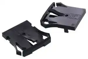
A7P-M-1
END CAP
⚠️ Reference pricing provided. In case of supply shortages, we will connect you with our trusted procurement partners to ensure your project's continuity.
- Manufacturer: OMRON ELECTRONIC COMPONENTS
- Product type: Controller Accessories
| Delivery and price | |
|---|---|
| Units per pack | 100 |
| Price | 1.95 € |
| Current stock | 200+ |
| Lead time | 7 days |
Datasheet

**Thumbwheel Switch A7PS/A7PH**

## **Dust-tight, Easy-to-Use, Push-operated Switches with Large Display Characters**

- Simple push mechanism and large, easy-toview numeric display make setting easy.

■ Dust penetration prevented with seal for the display windows.

## **Ordering Information**

## **Switches (Single Switch Units)**

|**Model**<br>**Classification**<br>**(See note 1.)**<br>**Terminals**<br>**Color**|**A7PS**<br>~~pO~~|**A7PS**<br>~~pO~~|**A7PH**|**A7PH**|
|---|---|---|---|---|
||**Snap-in**<br>**(front mounting)**<br>Katt<br>Leg)<br>Velaigl y||**Snap-in**<br>**(front mounting)**<br>**Long-life type**<br>IY<br>HOTTIE<br>\ Sialaig™i||
||**Solder terminals *1**||||
||**Lightgray**<br>~~es~~|**Black**<br>~~es~~|**Lightgray**<br>~~es~~|**Black**|
|**Output code number**|**Model**<br>~~es~~||||
|**03 (decimal code)**|**A7PS-203**<br>~~es~~|**A7PS-203-1**<br>~~es~~|**A7PH-203**<br>~~es~~|**A7PH-203-1**|
|**06 (binary coded decimal)**|**A7PS-206**<br>~~es~~<br>~~es~~|**A7PS-206-1**<br>~~es~~<br>~~es~~|**A7PH-206**<br>~~es~~<br>~~es~~|**A7PH-206-1**|
|**07 (binary coded decimal, with component-**<br>**adding provision) *2**|**A7PS-207**<br>~~es~~|**A7PS-207-1**<br>~~es~~|**A7PH-207**<br>~~es~~|**A7PH-207-1**|
|**19 (decimal code, with component-adding**<br>**provision)**|**A7PS-219**|**A7PS-219-1**|**A7PH-219**|**A7PH-219-1**|
|**54 (binary coded hexadecimal)**|**A7PS-254**<br>~~ee~~|**A7PS-254-1**<br>~~ee~~|**A7PH-254**<br>~~ee~~|**A7PH-254-1**|
|**55 (binary coded hexadecimal, with compo-**<br>**nent adding provision) *2**|**A7PS-255**|**A7PS-255-1**|---|---|


- Note: 1. The classification diagrams show 4 Switch Units combined with End Caps to create 4-digit displays.

   2. The model numbers given above are for 1 Switch Unit.

   3. Models with stoppers are also available. Add "-S@@" after the "203," "206," "207," "219," "254," or "255" in the model number and specify the display range in the @@. For example, to specify the range 0 to 6, add "-S06" to the model number (e.g., A7PS-206-S06-1).

   4. Models with +, - displays can also be produced. Add "-PM" after the "206" in the model number (e.g., A7PS-206-PM or A7PS-206-PM-1)

- *1. Models with PCB terminals are available.

- *2. Models with diodes are available. Add "-D" to the model number (e.g., A7PS-207-D or A7PS-207-D-1).

## **Accessories (Order Separately)**

Use accessories, such as End Caps and Spacers, with the Switch Units.

|**Accessory**<br>**Color**|**Accessory**<br>**Color**|**Lightgray**|**Black**|
|---|---|---|---|
|**End Caps**||**A7P-M ***|**A7P-M-1 ***|
|**Spacer**||**A7P-P**@<br>**(See note. ) ***|**A7P-P**@**-1**<br>**(See note. ) ***|
|**Connec-**<br>**tors**|**Solder terminals**|**NRT-C**||
|||**NRT-CN**||
||**PCB terminals**|**NRT-CP**||


Note: The @ in the Spacer model number stands for a letter in the range A to U. (Refer to the table in the following explanation about Spacers.)

* The minimum ordering unit is 10.

## **End Caps**

End Caps are used on the Switch Units at each end and allow all the Switch Units to be securely mounted to a panel. They come in pairs, one for the left and one for the right.

## **Spacers**

Spacers are used for creating extra space or gaps between the Switch Units and have the same dimensions as the Switch Units themselves.

There are also Spacers with engraved characters or symbols that can be used for indicating units, such as time and length. (Refer to the following table.) Consult your OMRON representative for details.

|**A**|**B**|**C**|**D**|**E**|**F**|
|---|---|---|---|---|---|
|No des-<br>ignation|SEC|MIN|H|g|kg|
|**H**<br>~~re~~|**J**<br>~~ee~~|**K**<br>~~ee~~|**L**<br>~~ee~~|**Q**<br>~~eee~~|**T**<br>~~eee~~|
|cm<br>~~re~~<br>~~a~~|m<br>~~ee ~~|C<br> ~~ee ~~|PCS<br> ~~ee~~|x 10SEC<br>~~eee~~|0<br>~~eee~~|


**1**

(c)Copyright OMRON Corporation 2007   All Rights Reserved.

http://www.ia.omron.com/

**A7PS/A7PH**

## **Specifications**

**Item Model A7PS A7PH** 50 VAC or 5 to 28 VDC 125 VAC or 5 to 28 VDC **Switching capacity (resistive load)** ~~Co~~ 1 mA to 0.1 A 10 μA to 0.15 A **Continuous carry current** ~~po~~ 1 A max. 3 A max. **Contact resistance** 300 mΩ max. **Insulation** ~~Qe~~ **Between non-connected terminals** 10 MΩ min. (at 500 VDC) 100 MΩ min. (at 500 VDC) **resistance Between terminal and non-current carrying part** 1,000 MΩ min. (at 500 VDC) **Dielectric** ~~po~~ **Between non-connected terminals** 600 VAC, 50/60 Hz for 1 min **strength** ~~po~~ **Between terminal and non-current carrying part** 1,000 VAC, 50/60 Hz for 1 min **Vibration resistance** 10 to 55 Hz, 1.5-mm double amplitude for 2 hours min. **Shock resistance** 490 m/s[2] min. **Mechanical** 100,000 operations min. 2,000,000 operations min. **Durability** ~~a~~ **Electrical** 50,000 operations min. 1,000,000 operations min. **Ambient temperature** Operating: -10°C to 65°C **Ambient humidity** Operating: 45% to 85% **Max. operating force** 6.37 N max.

## **Dimensions**

**==> picture [43 x 9] intentionally omitted <==**

**----- Start of picture text -----**<br>
(Unit: mm)<br>**----- End of picture text -----**<br>


## **Switches**

**==> picture [511 x 449] intentionally omitted <==**

**----- Start of picture text -----**<br>
A7PS-2@@(-1) 7.2 * (Unit: mm)<br>A7PH-2@@(-1) 10± 0.1 A 3 33.5 Number of  Size A Size B<br>Solder Terminal Switches (n) (n x 10 + 12) (n x 10 + 9)<br>1 22 19<br>2 32 29<br>33 22.6 30 3 42 39<br>4 52 49<br>3 Solder terminal 5 62 59<br>4.6 4.3 6 72 69<br>Panel thickness: 1 to 3<br>7 82 79<br>*If the output code is 03,06 or 54, the dimension is 43;<br>8 92 89<br> if the output code is 07,19 or 55, the dimension is 55.<br>9 102 99<br>Panel Cutout 10 112 109<br>Note: 1. The dimensions above include both End<br>Hie) wr 31- 0.40 Caps, and will increase 10 mm for each Spacer inserted.<br>2. Unless otherwise specified, a tolerance<br>4.5 (My 8.6 1BP= 10 [±] [0.2] L B A [+1] 0 L The tolerance for multiple connection is of ±0.4 mm applies to all dimensions.<br>±(number of units x 0.4) mm.<br>Accessories (Order Separately)<br>End Caps for Push-operated Switches<br>A7P-M(-1) Snap-in Panel Mounting<br>Left Side ( 39) Right Side (39)<br>33 33<br>4 3 6 6 3 4<br>| 4 whe |<br>33.5 4 33.5<br>4.4<br>“i 3 0 (4.3) i. 4.5 4.5 JF (4.3) Gi 30<br>4.5<br>Spacers for Push-operated Switches<br>A7P-P@(-1) Snap-in Panel Mounting<br>32.7 30 [±][ 0.1]<br>4.5 Jt8 E (36.5) H —_ “IJ<br>10 [±][ 0.05]<br>The @ in the Spacer model number stands for a letter in the range A to U. (Refer to the table under the explanation about Spacers on page 1.)<br>**----- End of picture text -----**<br>


Note: Unless otherwise indicated, dimensional tolerances for dimensions in the models above are ± 0.4 mm.

**2**

(c)Copyright OMRON Corporation 2007   All Rights Reserved.

http://www.ia.omron.com/

**A7PS/A7PH**

## **Connectors**

**==> picture [508 x 221] intentionally omitted <==**

**----- Start of picture text -----**<br>
(These devices allow Switches to be quickly removed for maintenance and inspection of connectivity, and quickly re-installed.)<br>NRT-C Solder Terminals NRT-CN Solder Terminals NRT-CP PCB Terminals<br>eT we y ‘ ~ wg aesAf 7<br>aS, & Tah<br>48 3 4 3 4<br>42 [±] [0.15] 30+ 0.30 30.2 [±][ 0.1]<br>30.2 3 4 [±][ 0.1] Two, 3.3 dia. 7.8 +0- 0.3 7.8 - 00.1 25.4 [±][ 0.2]<br>7.8 +o - 0.10  Vaitatatatoowermtatatatml| Cg ‘aSto a al<br>20.5 f ie 9 j d> e 13.5 4 1elliptic×2 17.5 — 9 4— 13.5<br>hole<br>9<br>13.5<br>20.5 Tia P= 2.54 4 3 [±][0.15] | P= 2.54 0.6 × 0.6 |<br>| tt UU 25.4 [±][ 0.2] Sem 25.4 i [±][ 0.2] n — 3 [±] [0.15]<br>Mi je -<br>! P= 2.54 3 [±][ 0.15] 1 2 3 4 5 6 7 8 91011 1 23 45 67 89 1011<br>__ 2 5.4 [±][ 0.2] _, | a AA a |<br>1 3 9 11 i 32 —— 32<br>2 10 6<br>—— 32 Note: Unless otherwise indicated, dimensional tolerances for dimensions in the models above are ± 0.4 mm.<br>UP<br>UP<br>UP<br>**----- End of picture text -----**<br>


## **Inserting Connectors**

Insert Connectors with the "UP" arrow pointing up.

**==> picture [35 x 7] intentionally omitted <==**

**----- Start of picture text -----**<br>
Connector<br>**----- End of picture text -----**<br>


## **Output Codes/Terminals**

- Switches with output codes 06 or 07 both use binary coded decimal but Switches with output code 07 have a componentadding provision. Similarly, Switches with output codes 54 or 55 both use binary coded hexadecimal but Switches with output code 55 have a componentadding provision.

- How to Read Output Codes For example, when the dial position is "3," the common terminal C on the Switch is connected to terminals 1 and 2. When the Switch is inserted into the Connector, the common terminal C becomes connector terminal 3, and terminals 1 and 2 become connector terminals 5 and 7 respectively.

**==> picture [336 x 352] intentionally omitted <==**

**----- Start of picture text -----**<br>
Output code number Terminals Output codes<br>9 Switch Unit  Common ter-<br>8 Model Terminals connected to common<br>76 P= 2.54 or Connector minal number<br>5 C 4 30 SwitchUnit C 0 1 2 3 4 5 6 7 8 9<br>03 Twenty  3210 03,19 Connec-tor 6 1 2 3 4 5 7 8 9 10 11<br>-two,1.1-dia.   i 3 2.5 Po 0 ●<br>holes 1 ●<br>ee ee<br>Po 2 ●<br>Forty-four, 1-dia. holes a 3 ee ●<br>9 8765 P= 2.5412.7 Dial 45 ● ●<br>C 4 30 6 ●<br>19 321 12.7 7 ●<br>0<br>8 ●<br>ti 8.5 4.53 2.5 aa 9 eeee ee ●<br>Component-adding provision Note: The solid dot ● indicates that the internal switch is ON<br>(i.e., connected to the common terminal).<br>84 P= 5.08 Model or ConnectorSwitch Unit  minal numberCommon ter- nected to commonTerminals con- * Terminal 3 is the common terminal<br>06 2 1 30 SwitchUnit C 1 2 4 8 for the component-adding provision.<br>Ten,  1.1-dia.holes ii 3 : C 2.5 0607 P|(EE Connec-Connec-tortor 1.3 3 * 5 7 9 11<br>0<br>| tt<br>1 ●<br>84 P= 5.08 2 ● Note: The solid dot ●<br>2 3 ● ● indicates that<br>1 4 30 4 ● the internal<br>07 Twenty -three,1.1-dia.  holes mn 8.5 4.53 C 2.5 Dial Po 567 ●● ●● ●●● switch is ON (i.e., connected to the common terminal).<br>8 ●<br>Component-adding provision ee ee<br>a 9 ● ee ●<br>**----- End of picture text -----**<br>


**3**

(c)Copyright OMRON Corporation 2007   All Rights Reserved.

http://www.ia.omron.com/

**A7PS/A7PH**

**==> picture [257 x 294] intentionally omitted <==**

**----- Start of picture text -----**<br>
Output code number Terminals Output codes<br>Model or ConnectorSwitch Unit  minal numberCommon ter- connected to Terminals common<br>SwitchUnit C 1 2 4 8<br>54 54 Connec-tor 3 5 7 9 11<br>55 Connec-tor 1<br>Ten, 1.1-dia. 0<br>holes i 25 ee eee<br>FCC 1 ●<br>PY 2 ●<br>ee 3 ● ●<br>FOU 4 ●<br>FCC 5 ● ●<br>PY 6 ● ●<br>Dial ee 7 ● ● ●<br>_— es 8 ●<br>ee 9 ● ●<br>A ● ●<br>55 B ● ● ●<br>papeeimnl PE<br>Twenty  C ● ●<br>-three, D ● ● ●<br>1.1-dia.<br>holes E ● ● ●<br>[OUT F ● ● ● ●<br>Component-adding provision Note: 1. The solid dot l indicates that the<br>internal switch is ON<br>(i.e., connected to the common<br>terminal).<br>**----- End of picture text -----**<br>


## **Ordering Procedure**

Place orders as shown in the example below, specifying the model and number.

**7**

1. A7P-M (End Caps): 1 set

2. A7PS-203 (Switch Unit): 1 piece

3. A7PS-206 (Switch Unit): 1 piece

4. A7P-PA (Spacer): 1 piece

5. A7PS-207 (Switch Unit): 1 piece

6. A7PS-219 (Switch Unit): 1 piece

Note: Standard products are not factory-assembled for shipment. Contact your OMRON representative for details on ordering factory-assembled sets. 7. NRT-C (Connector): 4 pieces

**==> picture [123 x 7] intentionally omitted <==**

**----- Start of picture text -----**<br>
1 2 3 4 5 6 1<br>**----- End of picture text -----**<br>


## **Safety Precautions**

## **Refer to** _**Precautions for Correct Use**_ **on in the** _**Technical Guide for Thumbwheel Switches**_ **.**

## **Precautions for Correct Use**

## **Handling**

- The molded components of the Switch use polyacetal resin and ABS resin. It is recommended that alcohol is used to wipe off dirt and smudges from the molded components. Take care to prevent the alcohol from getting inside.

- A7P Thumbwheel Switches are dust-proof, but they are not dripproof. Do not use them in areas subject to water or oil exposure.

- Do not allow solder flux or alcohol to enter the Switch.

- Do not push the (+) and (-) operating push-buttons at the same time.

**4**

(c)Copyright OMRON Corporation 2007   All Rights Reserved.

http://www.ia.omron.com/

## **Safet Precautions for All Thumbwheel Switches y**

**For precautionary information on individual products, refer to** _**Safety Precautions**_ **in the relevant section.**

## **WARNING**

**Electric shock may possibly occur. Do not perform wiring work or touch the charged parts of terminals while power is supplied to the Switch.**

## **Precautions for Correct Use**

**For details, refer to** _**Precautions for Correct Use of Thumbwheel Switches**_ **in** _**Technical Guide for Switches and Level Control Equipment**_ **.**

**C-1**

(c)Copyright OMRON Corporation 2007   All Rights Reserved.

http://www.ia.omron.com/

## **Technical Guide for Thumbwheel Switches**

## **Precautions for Correct Use**

## **Environment**

Do not use where gases are generated (ammonia, chlorine, sulfur dioxide).

Although Switches are of nearly dust-proof construction, they are not drip-proof, therefore do not use in areas subject to water or oil exposure and do not operate with wet or oily hands. (The A7MD has a dust-proof construction on contact parts, but consider your installation location carefully. The A7MA is not of dust-proof construction.)

Provide additional dust-proofing measures, such as using a dustproof cover, when using in sand-exposed areas.

## **Storage**

Do not store Switches in areas subject to high temperature or high humidity, or store them in room-temperature areas for extended periods of time. Doing so may cause oxidation of the terminals or problems with solder. It is also recommended that long periods of storage be avoided in general.

## **Handling**

## **Models with PCB Terminals**

When using models with PCB terminals, make the terminal insertion holes in the back board (mother board) 1 mm or larger in diameter.

Do not use excessive force in handling models with PCB terminals. In particular, take care to avoid dropping them as the terminals might bend or break.

Reference: Terminals can withstand a force of 7.84 N for 1 minute or more (A7D: 4.9 N for 10 seconds or more), and survive bending of 20 without breaking after returning to original position. Withstanding the repetitive application of external pressure, however, is beyond the scope of Switch specifications.

## **Connectors**

Insert Connectors while keeping the arrow pointing up (refer to A7BS/A7BL and A7PS/A7PH for details).

Connector insertion load is about 14.7 N for each A7B-C and 34.3 N for each NRT-C.

Wiring

After wiring has been completed, ensure an appropriate insulation distance.

Set-up

Do not use the Switch in the normally-pressed state. Doing so may occasionally result in premature deterioration of parts and changes in the characteristics.

Do not touch charged parts, such as terminals, while the power is ON.

Do not connect more than one power supply to a single Switch. Doing so may result in circuit malfunctions and short-circuits. When changing settings, do not touch the operating buttons if your fingers are wet or there is oil or any other foreign substance on your fingers.

It is recommended that alcohol is used to wipe off dirt and smudges from the molded-plastic cases. Take care to prevent the alcohol from getting inside.

Do not use thinner or other solutions which might damage the plastic.

When connecting Switches, fit the mating parts together. When separating Switches, use a screwdriver as shown in the figure below; disconnect them by releasing the top and bottom hooks. Be careful not to bend the hooks.

## **Soldering**

Note the following points when soldering printed circuit boards: Automatic Soldering

Do not use dip cleaning. Doing so may result in flux penetration of the Switch interior, causing contact and rotational defects. Clean the flux as shown in Figure 1, tilting the Switch 80 or less and using a brush to apply the solvent only to the back of the board. It may also be cleaned by dipping only the back of the board into the solvent and then using a brush to clean.

Dip Soldering

When applying flux solvent, the dipping time is a maximum of 2 seconds. As shown in Figure 2, avoid flooding the top surface of the printed circuit board with flux. Using a brush to apply flux further reduces the danger of flux penetration. When cleaning flux with a brush, tilt the Switch 80 or less, as shown in Figure 1, in order to prevent flux from flowing onto the switch mounting surface. Clean flux as described above under _Automatic Soldering_ .

**==> picture [174 x 76] intentionally omitted <==**

**----- Start of picture text -----**<br>
Figure 1 Figure 2<br>Top surface<br>Back surface  of board<br>of board<br>Wipe away flux<br>80° or less with a brush.<br>**----- End of picture text -----**<br>


## Using a Soldering Iron

Do not push the (+) and (-) operating push-buttons at the same time.

Do not drop the Switch. Doing so may possibly result in deformation of the terminals, damage to the PCB, or damage to the resin catch (for connecting) on the side of the Switch.

Use a 30-W soldering iron at a temperature of 350 C for a maximum of 3 seconds, and flush as described above. Do not apply force to the terminals during soldering and for 3 minutes after soldering is completed. Doing so may result in conduction or operation failure.

Ensure that soldering flux and alcohol do not penetrate into the Switch interior

The output may be unstable while the pushbuttons are being pressed due to the structure of the Thumbwheel Switch. Read the output signal only after the display has stopped moving.

**C-2**

(c)Copyright OMRON Corporation 2007   All Rights Reserved.

http://www.ia.omron.com/

## **Read and Understand This Catalog**

Please read and understand this catalog before purchasing the products. Please consult your OMRON representative if you have any questions or comments.

## **Warranty and Limitations of Liability**

## **WARRANTY**

OMRON's exclusive warranty is that the products are free from defects in materials and workmanship for a period of one year (or other period if specifi ed) from date of sale by OMRON.

OMRON MAKES NO WARRANTY OR REPRESENTATION, EXPRESS OR IMPLIED, REGARDING NON-INFRINGEMENT, MERCHANTABILITY, OR FITNESS FOR PARTICULAR PURPOSE OF THE PRODUCTS. ANY BUYER OR USER ACKNOWLEDGES THAT THE BUYER OR USER ALONE HAS DETERMINED THAT THE PRODUCTS WILL SUITABLY MEET THE REQUIREMENTS OF THEIR INTENDED USE. OMRON DISCLAIMS ALL OTHER WARRANTIES, EXPRESS OR IMPLIED.

## **LIMITATIONS OF LIABILITY**

OMRON SHALL NOT BE RESPONSIBLE FOR SPECIAL, INDIRECT, OR CONSEQUENTIAL DAMAGES, LOSS OF PROFITS, OR COMMERCIAL LOSS IN ANY WAY CONNECTED WITH THE PRODUCTS, WHETHER SUCH CLAIM IS BASED ON CONTRACT, WARRANTY, NEGLIGENCE, OR STRICT LIABILITY.

In no event shall responsibility of OMRON for any act exceed the individual price of the product on which liability is asserted.

IN NO EVENT SHALL OMRON BE RESPONSIBLE FOR WARRANTY, REPAIR, OR OTHER CLAIMS REGARDING THE PRODUCTS UNLESS OMRON'S ANALYSIS CONFIRMS THAT THE PRODUCTS WERE PROPERLY HANDLED, STORED, INSTALLED, AND MAINTAINED AND NOT SUBJECT TO CONTAMINATION, ABUSE, MISUSE, OR INAPPROPRIATE MODIFICATION OR REPAIR.

## **Application Considerations**

## **SUITABILITY FOR USE**

OMRON shall not be responsible for conformity with any standards, codes, or regulations that apply to the combination of products in the customer's application or use of the product.

At the customer's request, OMRON will provide applicable third party certifi cation documents identifying ratings and limitations of use that apply to the products. This information by itself is not suffi cient for a complete determination of the suitability of the products in combination with the end product, machine, system, or other application or use.

The following are some examples of applications for which particular attention must be given. This is not intended to be an exhaustive list of all possible uses of the products, nor is it intended to imply that the uses listed may be suitable for the products:

- Outdoor use, uses involving potential chemical contamination or electrical interference, or conditions or uses not described in this catalog.

- Nuclear energy control systems, combustion systems, railroad systems, aviation systems, medical equipment, amusement machines, vehicles, safety equipment, and installations subject to separate industry or government regulations.

- Systems, machines, and equipment that could present a risk to life or property.

Please know and observe all prohibitions of use applicable to the products.

NEVER USE THE PRODUCTS FOR AN APPLICATION INVOLVING SERIOUS RISK TO LIFE OR PROPERTY WITHOUT ENSURING THAT THE SYSTEM AS A WHOLE HAS BEEN DESIGNED TO ADDRESS THE RISKS, AND THAT THE OMRON PRODUCT IS PROPERLY RATED AND INSTALLED FOR THE INTENDED USE WITHIN THE OVERALL EQUIPMENT OR SYSTEM.

## **Disclaimers**

## **CHANGE IN SPECIFICATIONS**

Product specifi cations and accessories may be changed at any time based on improvements and other reasons.

It is our practice to change model numbers when published ratings or features are changed, or when signifi cant construction changes are made. However, some specifi cations of the product may be changed without any notice. When in doubt, special model numbers may be assigned to fi x or establish key specifi cations for your application on your request. Please consult with your OMRON representative at any time to confi rm actual specifi cations of purchased product.

## **DIMENSIONS AND WEIGHTS**

Dimensions and weights are nominal and are not to be used for manufacturing purposes, even when tolerances are shown.

## **ERRORS AND OMISSIONS**

The information in this catalog has been carefully checked and is believed to be accurate; however, no responsibility is assumed for clerical, typographical, or proofreading errors, or omissions.

## **PERFORMANCE DATA**

Performance data given in this catalog is provided as a guide for the user in determining suitability and does not constitute a warranty. It may represent the result of OMRON’s test conditions, and the users must correlate it to actual application requirements. Actual performance is subject to the OMRON Warranty and Limitations of Liability.

## **PROGRAMMABLE PRODUCTS**

OMRON shall not be responsible for the user's programming of a programmable product, or any consequence thereof.

## **COPYRIGHT AND COPY PERMISSION**

This catalog shall not be copied for sales or promotions without permission.

This catalog is protected by copyright and is intended solely for use in conjunction with the product. Please notify us before copying or reproducing this catalog in any manner, for any other purpose. If copying or transmitting this catalog to another, please copy or transmit it in its entirety.

In the interest of product improvement, specifications are subject to change without notice.

2007.3

OMRON Corporation

Industrial Automation Company

http://www.ia.omron.com/

(c)Copyright OMRON Corporation 2007   All Rights Reserved.
Updated at February 9, 2023
About Novapart
Novapart is a B2B electronic component broker specialising in stock shortages and cost reduction. We source hard-to-find parts and identify compliant alternatives across a catalogue of 540,000+ components from 500+ manufacturers.
Learn more →Stock Shortage Specialist
When a component is unavailable, discontinued or has an unacceptable lead time, we tap into our network of vetted European and Asian distributors to source what you need — without compromising on quality or traceability.
Request a quote →Compliant Alternatives
We identify pin-to-pin, electrically equivalent substitutes that meet the same certifications (RoHS, AEC-Q100, REACH) as your original specification — validated against datasheets, not just part numbers. Often at a lower cost.
BOM Analysis service →