


A2W-AT2.5-WC1
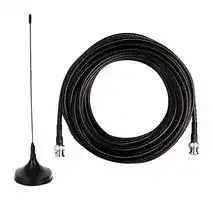
MAGNETIC BASE ANTENNA, 2.5M, IP65
- Manufacturer: OMRON INDUSTRIAL AUTOMATION
- Product type: Controller Accessories
- Current Rating:-; Product Range:A2W Series
- Product Range: A2W Series
- Current Rating: -
| Delivery and price | |
|---|---|
| Units per pack | 250 |
| Price | 46.94 € |
| Current stock | 10+ |
| Lead time | 30 days |
**New Product**

## **Wireless Pushbutton Switch A2W**

## **Wireless switch using sub-GHz band Combines wireless reliability and ease-of-use in consideration of work environments**

- Sub-GHz band for reduced interference and better signal propagation to difficult-to-reach areas

- Visualization of impedance to wireless transmission because of damage or noise, using Master Unit error output

- Visualization of Slave button reception status using reception confirmation LEDs

- Transmission distance independent of the transmission position of the Slave button

For the most recent information on models that have been certified for safety standards, refer to your OMRON website.

- Visualization of configuration using PC tools * that avoid erroneous ID registration

- Visualization of signal quality in display and usage environments using PC tools *

- 8 outputs with focus on decentralized control

- Self-power generation eliminates battery replacement and enhances safety and energy saving in the Slave button

- Slave button's shape allows easy use of buttons

- Release planned for April 2018

## **System Components**

Master Unit A2W-R@@-WC1

**==> picture [110 x 79] intentionally omitted <==**

**----- Start of picture text -----**<br>
Display board or PT, etc.<br>Bm 7,024<br>PLC, etc.<br>**----- End of picture text -----**<br>


**==> picture [210 x 44] intentionally omitted <==**

**----- Start of picture text -----**<br>
Transistor output<br>Up to 8 points<br>OOOOCIOOOOO|<br>**----- End of picture text -----**<br>


**==> picture [36 x 7] intentionally omitted <==**

**----- Start of picture text -----**<br>
Wireless<br>**----- End of picture text -----**<br>


The Slave button transmits an operation signal to the Master Unit, and the Master Unit responds a reception confirmation signal to the Slave button.

Slave button A2W-T@-WC1 (Up to 8 points)

**1**

**A2W Model Number Structure**

## **Model Number Structure Slave button**

**==> picture [256 x 18] intentionally omitted <==**

**----- Start of picture text -----**<br>
A 2 W-  @ @  - WC @ @ @ @ @ @<br>**----- End of picture text -----**<br>


|1<br>2<br>**1.**<br>**Slave button**<br>T<br>**5.**|1<br>2<br>**1.**<br>**Slave button**<br>T<br>**5.**|3<br>4<br>5<br>6<br>7<br>**2.**<br>**Frequency (MHz)**<br>A<br>929.2<br>**6.**|3<br>4<br>5<br>6<br>7<br>**2.**<br>**Frequency (MHz)**<br>A<br>929.2<br>**6.**|3<br>4<br>5<br>6<br>7<br>**2.**<br>**Frequency (MHz)**<br>A<br>929.2<br>**6.**|**3.**<br>**Protocol**<br>1<br>OMRON's protocol<br>**7.**<br>**Flange color**<br>R<br>Red<br>Y<br>Yellow<br>B<br>Black|**3.**<br>**Protocol**<br>1<br>OMRON's protocol<br>**7.**<br>**Flange color**<br>R<br>Red<br>Y<br>Yellow<br>B<br>Black|**4.**|**4.**|
|---|---|---|---|---|---|---|---|---|
||||||||**Area**||
||||||||JP|Japan|
||||||||||
|**Button type**||**Button color**|||||||
|1|Mushroom|R|Red||R|Red|||
|2|Fullguard|G|Green||Y|Yellow|||
|||Y|Yellow||B|Black|||
|||A|Blue||||||
|||W|White||||||
|||B|Black||||||


- **Note:** This product is a wireless device that conforms to the radio regulations of Japan. It cannot be used outside of Japan.

   - Besides Japan, we also provide models that conform to the radio regulations of the USA, Canada, Mexico, Europe (EU), and Brazil. For product details, please contact us separately.

## **Master Unit**

## A 2 W- **@ @ @** - WC **@ @ @**

**==> picture [369 x 123] intentionally omitted <==**

**----- Start of picture text -----**<br>
1 2 3 4 5<br>1. 2. 3.<br>Master Unit Frequency (MHz) Output Configuration<br>R A 929.2 N Sinking Outputs<br>P Sourcing Outputs<br>4. 5.<br>Protocol Area<br>1 OMRON's protocol JP Japan<br>**----- End of picture text -----**<br>


- **Note:** This product is a wireless device that conforms to the radio regulations of Japan. It cannot be used outside of Japan.

   - Besides Japan, we also provide models that conform to the radio regulations of the USA, Canada, Mexico, Europe (EU), and Brazil. For product details, please contact us separately.

**2**

**A2W**

## **Ordering Information**

## **Unit**

|**Type**|**Button type**|**Frequency (MHz)**|**Area**|**Button color**|**Flange color**|**Model**|
|---|---|---|---|---|---|---|
|Slave button|Mushroom|929.2|Japan|Red|Black|**A2W-TA-WC1 JP1RB**|
||||Japan|Green|Black|**A2W-TA-WC1 JP1GB**|
||||Japan|Yellow|Black|**A2W-TA-WC1 JP1YB**|
||||Japan|Blue|Black|**A2W-TA-WC1 JP1AB**|
||||Japan|White|Black|**A2W-TA-WC1 JP1WB**|
||||Japan|Black|Red|**A2W-TA-WC1 JP1BR**|
||||Japan|Black|Yellow|**A2W-TA-WC1 JP1BY**|
||||Japan|Black|Black|**A2W-TA-WC1 JP1BB**|
||Full guard||Japan|Red|Black|**A2W-TA-WC1 JP2RB**|
||||Japan|Green|Black|**A2W-TA-WC1 JP2GB**|
||||Japan|Yellow|Black|**A2W-TA-WC1 JP2YB**|
||||Japan|Blue|Black|**A2W-TA-WC1 JP2AB**|
||||Japan|White|Black|**A2W-TA-WC1 JP2WB**|
||||Japan|Black|Red|**A2W-TA-WC1 JP2BR**|
||||Japan|Black|Yellow|**A2W-TA-WC1 JP2BY**|
||||Japan|Black|Black|**A2W-TA-WC1 JP2BB**|


## **Master Unit**

|**Type**|**Frequency (MHz)**|**Area**|**Output configuration**|**Model**|
|---|---|---|---|---|
|Master Unit|929.2|Japan|Sinking Outputs|**A2W-RAN-WC1 JP**|
||||Sourcing Outputs|**A2W-RAP-WC1 JP**|


**Note:** This product is a wireless device that conforms to the radio regulations of Japan. It cannot be used outside of Japan.

Besides Japan, we also provide models that conform to the radio regulations of the USA, Canada, Mexico, Europe (EU), and Brazil. For product details, please contact us separately.

## **Options (sold separately)**

|**Type**|**Model**|**Remarks**|
|---|---|---|
|High-sensitivity magnetic-base antenna|**A2W-AT2.5-WC1**|Frequencies: all frequencies supported, cable length 2.5 m<br>Degree of protection: IP65|
|Slave button holder|**A2W-H-WC1**|One A2W-H-WC1 is included at purchase of a slave unit.|
|Slave button strap|**A2W-S-WC1**||


**3**

**A2W**

## **Ratings**

## **Wireless Specifications**

|**Item**|**Slave button model**|**A2W-TA-WC1 JP**@@@|
|---|---|---|
||**Master Unit model**|**A2W-RA**@**-WC1 JP**|
|**Set frequency**||929.2 MHz|
|**Frequency channels**||1 channel|
|**Transmission power**||1 mW max.|
|**Wireless service area**<br>**speed**|**communications**|100 kbit/s|
|**Communications method**||Simplex communications|
|**Number of wireless pushbuttons**<br>**connected**||8 max.|
|**Communications distance (line of sight)**||Approx. 100 m outdoors (with the included pencil antenna)|
|**Transmission time**||Approx. 3 ms (from Slave button transmission to Slave button reception)|
|**Repeater function**||Not supported.|


## **Applicable Standards**

|**Area**|**Wireless standards**|**Safety standards**|**EMC standards**|
|---|---|---|---|
|Japan|Conforms to ARIB STD-T108|Conforms to IEC 623680-1<br>Conforms to EN 62368-1|Conforms to EN 301 489-1<br>Conforms to EN 301 489-3|


## **Conformance to EN Standards**

Use a DC power line less than 3 m to conform to EN standards.

If a power line of 3 m or longer is required, extend the length at the Switching Power Supply's primary side (i.e., the AC power line).

## **Slave button**

## **Ratings**

|**Item**|**Specifications**|
|---|---|
|**Operating force**|25 N max.|
|**Number of operations**|1,000,000 operations|
|**Vibration resistance**|Frequency: 10 to 55 Hz, half amplitude: 0.75 mm<br>Sweep 5 min, 2 h|
|**Shock resistance**|1,000 m/s2<br>Direction: 3-axis, 6 directions|
|**Ambient operating temperature range**|-10 to +55°C (no condensation or freezing)|
|**Ambient operating humidity range**|20% to 90%, (no condensation)|
|**Atmosphere**|No corrosivegas|
|**Storage temperature range**|-40 to +70°C (no condensation or freezing)|
|**Storage humidity range**|20% to 90%, (no condensation)|
|**Degree of protection**|IP65|
|**Altitude**|2,000 m max.|
|**Weight**|100gmax.|


## **Reception Confirmation LED**

|**Item**|**Details**|
|---|---|
|**Green**|Reception success (received field strength “Strong”)|
|**Yellow**|Reception success (received field strength “Weak”)|
|**Red**|Reception failure|
|**Not lit**|Slave button fault (no signal transmission from Slave button)|


## **Operating Characteristics**

|**Item**|**Code**|**Unit**|**Initial standard value**|
|---|---|---|---|
|**Operating force**|OF|N|25 N max.|
|**Total travel**|TT|mm|6 mm|


**4**

**A2W**

## **Master Unit Ratings**

||**Item**|**Specifications**|
|---|---|---|
|**Master Unit**<br>**power supply**|**Rated voltage**|24 VDC|
||**Allowable voltage range**|21.6 to 26.4 VDC|
||**Power consumption**|2.4 W max.|
||**Input current**|0.1 A max.|
|**Output rated**|**Output points**|Output 8 points<br>One other point for error output|
||**Output circuit shared**<br>**voltage**|30 VDC max.|
||**Maximum load current**|50 mA per point|
||**Leakage current**|0.1 mA max.|
||**Residual voltage**|2.0 V max.|
||**Output logic**|One-shot (500 ms)|
||**Response time**|30 ms or less (from Slave button transmission to Master Unit signal output)|
||**Number of connected**<br>**Slave buttons**|8 max.|
|**Error clear**<br>**terminal**|**Residual voltage at short**|1.5 V or less, ON|
||**Leakage current**|0.1 mA or less, OFF (current at short: approx. 7 mA)|
|**Insulation resistance**||20 MΩmax. (100 VDC)<br>Between the case and power supply terminals and all outputs terminals<br>Between all power supplyterminals and all outputs terminals|
|**Dielectric strength**||1,000 VAC, 1 min.<br>Between the case and power supply terminals and all outputs terminals<br>Between all power supplyterminals and all outputs terminals|
|**Vibration resistance**||Frequency: 10 to 55 Hz, half amplitude: 0.42mm<br>3-Directional, 120 minutes each (1 sweep, 1 min. ×120 sweeps)|
|**Shock resistance**||150 m/s2<br>Direction of shock: 3-axis, 6 directions<br>Shock frequency: 3 × each direction, total 18|
|**Ambient operating temperature range**||-10 to +55°C (no condensation or freezing)|
|**Ambient operating humidity range**||20% to 90% (no condensation)|
|**Surrounding atmospheric conditions**||No corrosivegas|
|**Ambient storage temperature range**||-40 to +70°C (no condensation or freezing)|
|**Ambient operating humidity**||20% to 90% (no condensation)|
|**Degree of protection**||IP20|
|**Altitude**||2,000 m max.|
|**Memory protection**||Non-volatile memory (Number of write operations: 1,000,000)|
|**Weight**||150 g (not including antenna)<br>160g(includingantenna)|
|**Mounting**||DIN rail mounting<br>Screw mounting|


**5**

**A2W**

## **Parts Names and Functions**

## **Slave button**

**==> picture [227 x 323] intentionally omitted <==**

**----- Start of picture text -----**<br>
|||||||||||
|---|---|---|---|---|---|---|---|---|---|
|Button|
|Flange|
|Reception Confirmation LED|
|Strap hole|
|Master Unit|A|B|C|D|E|Q|P|
|S|
|R|
|U|
|T|
|W|V|
|F|G|H|I|J|K|L|M|N|O|

**----- End of picture text -----**<br>


**==> picture [512 x 368] intentionally omitted <==**

**----- Start of picture text -----**<br>
||||||||||||||
|---|---|---|---|---|---|---|---|---|---|---|---|---|
|Terminal|Terminal|
|Number|Name|Functions|Number|Name|Functions|
|name|name|
|A|24 VDC|Used to register or delete the ID of the Slave|
|Output|
|B|24 VDC|Power|R|-|settings|button to or from the output of the Master Unit.|
|C|0 V 1|supply terminals|Supply 24 VDC.|switch|Also used to reset the error output without using the error clear terminal.|
|D|0 V 2|Mode|
|E|CLR|Error clear terminal|Connect the error clear terminal to 0V (GND).|S|-|settings switch|Set the operation mode of the Master Unit to ID mode, TEST mode, and RUN mode.|
|F|OUT 1|T|-|Power LED|Lit green when the power is ON.|
|(PWR)|
|G|OUT 2|
|Lit red when there is a possibility that|
|H|OUT 3|Connects the output signal line.|U|-|Error LED|abnormality occurs in the master unit and it|
|I|OUT 4|Output|There are two output types: sinking and|(ERR)|will not output correctly according to the Slave|
|JK|OUT 5OUT 6|terminals|sourcing.••|A2W-RA2W-R|@@|N-WC1 P-WC1|@@@@|: Sourcing Outputs: Sinking Outputs|button operation.•|RUN mode or TEST mode|
|It lights according to the received electric|
|L|OUT 7|field strength of the received data.|
|M|OUT 8|Lit green:Lit red:|Received field strength is "Strong" Received field strength is "Weak"|
|Connects the error signal line.|•|ID mode|
|Error|There are two output types: sinking and|Received|Lit green when registration or deletion is|
|N|ERR|output terminal|sourcing.•|A2W-R|@|N-WC1|@@|: Sinking Outputs|V|-|field strength|success.Flashing green when registration or|
|•|A2W-R|@|P-WC1|@@|: Sourcing Outputs|LED (RCV)|deletion is failure.|
|Common|•|When error output occurs|
|O|COM|terminal for|Used as common for output and error output.|Lit green when the Master Unit setting data|
|error is detected.|
|outputs|
|Lit yellow when there is a possibility that the|
|Connect the included pencil antenna.|Master Unit will not output properly according|
|P|-|Antenna terminal|(Optional antenna A2W-AT2.5-WC1 can also be connected.)|•|RUN modeto the Slave button operation.|
|It transmits and receives data by wireless|
|communications via the antenna.|When outputting to the output terminal, the|
|corresponding output LED lit yellow.|
|•|Delete the Slave button registration|Output|•|TEST mode|
|information corresponding to the output settings switch.|W|-|LED(OUTPUT|It does not output to the output terminal, and the corresponding output LED lit|
|Q|-|Reset switch|•|By pressing the output settings switch in the "ERR CLR" state when an error output is|1 to 8)|•|yellow.ID mode|
|generated, error output will be reset.|The output LED corresponding to the|
|•|When the power is turned ON in the|output setting switch lit yellow.|
|pressed state, it is reset to the factory|
|setting.|

**----- End of picture text -----**<br>


**6**

**A2W**

## **Display Section**

|**LED**<br>**name**|**Color**|**Enabled mode**|**Status**|**Meaning**|
|---|---|---|---|---|
|PWR|Green|Always enabled|Lit|During Power Supply|
||||Not lit|No power supplied|
|RCV|Green<br>or<br>yellow|RUN/TEST<br>ID<br>Enabled only when<br>ERR LED is lit|Lit/Not lit|Received field strength monitor:<br>Lit green:<br>Received field strength is “Strong” (lit up for 500 msec)<br>Lit yellow:<br>Received field strength is “Weak” (lit up for 500 msec)<br>Not lit:<br>No received|
||||Lit/Not lit/<br>Flashing|ID registration:<br>Lit green:<br>ID registration successful (lit up for 3 s)<br>Not lit:<br>Data for ID registration not received<br>Flashing green: ID registration failed (flashes for 3 s after every 250 ms)|
|||||Delete ID:<br>Lit green:<br>ID deletion successful (lit up for 3 s)<br>Not lit:<br>Data for ID deletion not received<br>Flashing green: ID deletion failed (flashes for 3 s after every 250 ms)|
||||Lit/Not lit|Lit green:<br>Error in Master Unit setting data<br>Lit yellow:<br>Error in the most important function (wireless received, registration/verification, or output)<br>All not lit:<br>Error in CPU initialization process during startup|
|OUTPUT<br>1 to 8|Yellow|RUN/TEST<br>ID|Lit|Data is received from the ID assigned to the corresponding output|
||||Not lit|Data is not received from the ID assigned to the corresponding output|
||||Lit|Reads corresponding output settings switch values 1 to 8|
||||All Lit|Reads output settings switch value DEL|
||||All not lit|Reads output settings switch value ERR_CLR|
|ERR|Red|Always enabled|Lit|Error in CPU initialization processing at startup, or in Master Unit setting data, or in the most important<br>function (wireless received, registration/verification, or output)|
||||Not lit|No Master Unit error|


**Note:** For received field strength LED (RCV) green flashing, this also flashes even when attempting to select or reset a non-registered output settings No. and delete or reset.

## **Settings Switch**

## **Mode Settings Switch**

Set the operation mode of the Master Unit. Factory setting: ID

|**Operation mode**|**Function**|
|---|---|
|RUN|Communications mode: carry out normal communications|
|TEST|Test mode: Perform installation test such as reception<br>intensity measurement*|
|ID|ID mode: Register or delete Slave buttons|


* There is no output from the output terminal.

## **Output Settings Switch**

Register or delete the Slave button ID * for each output number of the Master Unit.

Factory setting: 1

|**No.**|**Enabled**<br>**mode**|**Other settings**<br>**requirements**|**Function**|
|---|---|---|---|
|1 to 8|ID|Continuous data<br>reception within a fixed<br>period from the Slave<br>button to be registered|Register the ID of the target<br>Slave button to be registered<br>in the specified output<br>number|
|||Press the Reset switch<br>(ON)|Delete IDs of all Slave<br>buttons registered in the<br>specified output number|
|DEL||Continuous data reception<br>within a fixed period from<br>the Slave button for which<br>the registration is to be<br>deleted|Delete the ID of the Slave<br>button to be deleted from the<br>registration list|
|||Press the Reset switch<br>(ON)|Delete all IDs from the<br>registration list|
|ERR<br>CLR|ERR LED<br>lit red<br>+<br>RCV LED<br>lit yellow|Press the Reset switch<br>(ON)|Execute the software reset of<br>the Master Unit|


- This is the identification number of the Slave button for wireless communications.

## **Reset Switch**

Execute resets of Master Unit. Factory Setting: Not pressed (OFF)

## **Setting Procedures Slave buttons Registration Setting**

- Set the output for the Slave button ID.

- When the mode settings switch has been set to "ID", the Slave button ID that has received the data during the same operation of the Slave button three or more times within three seconds, and the contents set in the output settings switch are linked.

- If you make "Wireless Push Buttons Registration setting" while another system is operating in the vicinity, erroneous settings may be made. Therefore, make the "Wireless Push Buttons Registration setting" in an environment in which other systems are not operating.

- In the ID deletion procedure, if the received field strength LED (RCV) flashes, then a non-registered port ID may be selected.

- At Slave button registration (ID registration/deletion procedures), confirm that the output LCD is lighting correctly for the output setting No. to select.

## **Wireless push button registration/deletion procedure**

- **Using the wireless push button**

**1.** Set the mode settings switch of the Master Unit to "ID".

**2.** Set the output settings switch of the Master Unit. 1 to 8: The output destination is set as outputs 1 to 8. DEL: The information about the received ID is deleted from the registration list.

**3.** Press the wireless push button three or more times to make sure that the received field strength LED (RCV) is lit.

**4.** Set the mode settings switch of the Master Unit to "RUN" or "TEST".

**Wireless push button deletion procedure**

- **Using the RESET switch**

**1.** Set the mode settings switch of the Master Unit to "ID".

**2.** Set the output settings switch of the Master Unit. 1 to 8: The ID information registered in outputs 1 to 8 is deleted. DEL: The information about all IDs is deleted from the registration list.

**3.** Press the Reset switch of the Master Unit until the received field strength LED (RCV) is lit.

**4.** Set the mode settings switch of the Master Unit to "RUN" or "TEST".

## **Resetting Error Output (RCV indicator lit yellow.) Using the RESET switch**

**1.** Set the output settings switch of the Master Unit to "ERR_CLR".

**2.** Press the Reset switch.

## **Using the error clear terminal**

**1.** Connect the error clear terminal to GND.

**7**

**A2W Dimensions**

(Unit: mm)

## **Unit**

**==> picture [487 x 635] intentionally omitted <==**

**----- Start of picture text -----**<br>
Slave button<br>A2W- @@ -WC1- @@ 1 @@<br>42 65 max. 32<br>40 dia.<br>Two, M3x6<br>42 Fine screw<br>26.5 35.2<br>(2.5)<br>p O Ee _]<br>A2W- @@ -WC1- @@ 2 @@<br>42 65 max. 32<br>34.4 dia.<br>Two, M3x6<br>Fine screw<br>42<br>26.5 35.2<br>(2.5)<br>Holder 24<br>A2W-H-WC1<br>Four, 5.6 dia.<br>One A2W-H-WC1 is<br>included at purchase of  46.6 24<br>a Slave button.<br>& 60.3 mai |<br>Mounting Hole Dimensions<br>Two, M5 screw hole or 5.2-dia. mounting hole<br>24.8<br>LL. o#<br>24±0.1<br>46.3<br>—a =u<br>Strap<br>A2W-S-WC1 32<br>Four, 3.2 dia. Slave button mounting screws:<br>Accessories (2 places)<br>32 ry" Be sure to use the accessory screws.<br>a eQA<br>1/4-20UNC (2 places)<br>33.5<br>ize 46.3 70.1<br>**----- End of picture text -----**<br>


**8**

**A2W**

## **Master Unit A2W-** @@@ **-WC** @@@

**==> picture [396 x 145] intentionally omitted <==**

**----- Start of picture text -----**<br>
50<br>46<br>34 34.5<br>(161.5)<br>(4.5)<br>94  * 90 (79.1)<br>(2)<br>Se 70 a (60.8) =<br>*  108 mm at installation on the wall (143.2)<br>**----- End of picture text -----**<br>


**==> picture [171 x 19] intentionally omitted <==**

**----- Start of picture text -----**<br>
High-sensitivity Magnetic Base Antenna<br>A2W-AT2.5-WC1<br>**----- End of picture text -----**<br>


**==> picture [217 x 180] intentionally omitted <==**

**----- Start of picture text -----**<br>
3 dia.<br>1.2 dia.<br>83±3<br>36<br>Lo<br>Fo 27 dia.  o ±2 T 2500 +100–0<br>**----- End of picture text -----**<br>


**9**

**A2W Connection**

## **Internal Connection Diagram (Master Unit)**

**==> picture [496 x 257] intentionally omitted <==**

**----- Start of picture text -----**<br>
Fuse Electrical circuit Antenna<br>24V DC<br>DC/DC converter DC/DC converter<br>INPUT Noise filter (24V DC�5V DC) (5V DC�3.3V DC) RF module<br>0V DC<br>CLR Memory<br>(EEPROM)<br>Voltage<br>detection Output circuit × 8<br>Photo coupler<br>1<br>Power LED (PWR) OUTPUT<br>8<br>Control section<br>Error LED (PWR)<br>Received field strength (CPU) ERR<br>LED (RCV)<br>Output LED × 8 COM<br>(OUTPUT1 to 8)<br>Operation switch<br>• Mode settings switch<br>• Output settings switch<br>• Reset switch<br>Serial<br>communications  PC CONN<br>section<br>**----- End of picture text -----**<br>


## **Output Specifications Operation Timing Chart**

## **Error Output Signal (Master Unit)**

**==> picture [475 x 178] intentionally omitted <==**

**----- Start of picture text -----**<br>
Press operation<br>Slave button Error output<br>Lit Power ON Momentary  Continuously error<br>power failures<br>Slave button<br>reception confirmation  Status Internal transistor<br>LED<br>Power is OFF. OFF<br>Normal operation ON<br>Error, or momentary  OFF<br>power failure<br>Lit<br>Master Unit RCV LED<br>Master Unit output ON<br>(Internal transistor ON)<br>Master Unit OUTPUT<br>500 ms<br>**----- End of picture text -----**<br>


**Note:** If you press two or more Slave buttons simultaneously within 2 ms, operation of the Slave button after that may not be sent to the Master Unit.

## **Output/Error Output Circuit Diagram (Master Unit)**

**==> picture [271 x 141] intentionally omitted <==**

**----- Start of picture text -----**<br>
Output/Error output circuits diagram Output/Error output circuits diagram<br>(Sinking Outputs) (Sourcing Outputs)<br>OUT1 COM<br>OUT1<br>OUT8<br>OUT8<br>ERR<br>COM ERR<br>**----- End of picture text -----**<br>


**10**

**A2W**

## **Recommended Ferrules and Crimp Tools Coating peeling amount**

|**Recommend Wire Type**|**Recommend Wire Type**|**Recommend Wire Type**|**Recommend Wire Type**|**Stripping length**<br>**(Ferrules not used)**|**Stripping length**<br>**(Ferrules not used)**|**Stripping length**<br>**(Ferrules not used)**|
|---|---|---|---|---|---|---|
|0.25 to 1.5 mm2/AWG 24 to AWG 16||||8 mm|||
|2 to 2.5 mm2/AWG 14||||10 mm|||
||||||||
|**Applicable**<br>**wire**||**Ferrule**<br>**conductor**<br>**length**<br>**(mm)**|**Stripping**<br>**length (mm)**<br>**(Ferrules not**<br>**used)**|**Recommended ferrules**|||
|**(mm2)**|**(AWG)**|||**Manufactu-**<br>**red by**<br>**Phoenix**<br>**Contact**|**Manufactu-**<br>**red**<br>**by Wago**|**Manufa-**<br>**ctured by**<br>**Weidmul-**<br>**ler**|
|0.25|24|8|10|AI 0, 25-8|H0.25/12|216-301|
|||10|12|AI 0, 25-10|---|---|
|0.34|22|8|10|AI 0, 34-8|H0.34/12|216-302|
|||10|12|AI 0, 34-10|---|---|
|0.5|20|8|10|AI 0, 5-8|H0.5/14|216-201|
|||10|12|AI 0, 5-10|H0.5/16|216-241|
|0.75|18|8|10|AI 0, 75-8|H0.75/14|216-202|
|||10|12|AI 0, 75-10|H0.75/16|216-242|
|1/1.25|18/17|8|10|AI 1-8|H1.0/14|216-203|
|||10|12|AI 1-10|H1.0/16|216-243|
|1.25/1.5|17/16|8|10|AI 1, 5-8|H1.5/14|216-204|
|||10|12|AI 1, 5-10|H1.5/16|216-244|
|2.5|14|10|12|AI 2,5-10|H2.5/16DS||
|Recommended Crimp Tools||||CRIMPFOX6<br>CRIMPFOX6T-F<br>CRIMPFOX10S|PZ6 roto|Variocrim<br>p4|


## **Recommended Flat-Blade Screwdrivers**

Use a flat-blade screwdriver to connect and remove wires. Use one of the following flat-blade screwdrivers.

The following table shows manufacturers and models as of 2015/Dec.

|**Recommended Flat-Blade Screwdrivers**<br>Use a flat-blade screwdriver to connect and remove wires.<br>Use one of the following flat-blade screwdrivers.<br>The following table shows manufacturers and models as of 2015/Dec.|**Recommended Flat-Blade Screwdrivers**<br>Use a flat-blade screwdriver to connect and remove wires.<br>Use one of the following flat-blade screwdrivers.<br>The following table shows manufacturers and models as of 2015/Dec.|
|---|---|
|Side view<br>0.4 mm<br>2.5 mm dia.<br>2.5 mm<br>Front view||
|**Model**|**Manufacture**|
|ESD 0,40 × 2,5|Wera|
|SZS 0,4 × 2,5<br>SZF 0-0,4 × 2,5*|Phoenix Contact|
|0.4 × 2.5 × 75 302|Wiha|
|AEF.2,5 × 75|Facom|
|210-719|Wago|
|SDI 0,4 × 2,5 × 75|Weidmuller|


      - The SZF 0-0,4 × 2,5 (manufactured by Phoenix Contact) can be procured through an OMRON exclusive purchase form (XW4Z-00B).

- **Note: 1.** Make sure that the outer diameter of the wire coating is smaller than the inner diameter of the insulation sleeve of the recommended ferrule.

   **2.** Make sure that the ferrule processing dimensions conform to the following figures.

8 to 10 mm 2.6 mm max. 2.8 mm max.

**11**

**MEMO**

**12**

## **Terms and Conditions Agreement**

## **Read and understand this catalog.**

Please read and understand this catalog before purchasing the products. Please consult your OMRON representative if you have any questions or comments.

## **Warranties.**

(a) Exclusive Warranty. Omron’s exclusive warranty is that the Products will be free from defects in materials and workmanship for a period of twelve months from the date of sale by Omron (or such other period expressed in writing by Omron). Omron disclaims all other warranties, express or implied.

(b) Limitations. OMRON MAKES NO WARRANTY OR REPRESENTATION, EXPRESS OR IMPLIED, ABOUT NON-INFRINGEMENT, MERCHANTABILITY OR FITNESS FOR A PARTICULAR PURPOSE OF THE PRODUCTS. BUYER ACKNOWLEDGES THAT IT ALONE HAS DETERMINED THAT THE PRODUCTS WILL SUITABLY MEET THE REQUIREMENTS OF THEIR INTENDED USE.

Omron further disclaims all warranties and responsibility of any type for claims or expenses based on infringement by the Products or otherwise of any intellectual property right. (c) Buyer Remedy. Omron’s sole obligation hereunder shall be, at Omron’s election, to (i) replace (in the form originally shipped with Buyer responsible for labor charges for removal or replacement thereof) the non-complying Product, (ii) repair the non-complying Product, or (iii) repay or credit Buyer an amount equal to the purchase price of the non-complying Product; provided that in no event shall Omron be responsible for warranty, repair, indemnity or any other claims or expenses regarding the Products unless Omron’s analysis confirms that the Products were properly handled, stored, installed and maintained and not subject to contamination, abuse, misuse or inappropriate modification. Return of any Products by Buyer must be approved in writing by Omron before shipment. Omron Companies shall not be liable for the suitability or unsuitability or the results from the use of Products in combination with any electrical or electronic components, circuits, system assemblies or any other materials or substances or environments. Any advice, recommendations or information given orally or in writing, are not to be construed as an amendment or addition to the above warranty.

See http://www.omron.com/global/ or contact your Omron representative for published information.

## **Limitation on Liability; Etc.**

OMRON COMPANIES SHALL NOT BE LIABLE FOR SPECIAL, INDIRECT, INCIDENTAL, OR CONSEQUENTIAL DAMAGES, LOSS OF PROFITS OR PRODUCTION OR COMMERCIAL LOSS IN ANY WAY CONNECTED WITH THE PRODUCTS, WHETHER SUCH CLAIM IS BASED IN CONTRACT, WARRANTY, NEGLIGENCE OR STRICT LIABILITY.

Further, in no event shall liability of Omron Companies exceed the individual price of the Product on which liability is asserted.

## **Suitability of Use.**

Omron Companies shall not be responsible for conformity with any standards, codes or regulations which apply to the combination of the Product in the Buyer’s application or use of the Product. At Buyer’s request, Omron will provide applicable third party certification documents identifying ratings and limitations of use which apply to the Product. This information by itself is not sufficient for a complete determination of the suitability of the Product in combination with the end product, machine, system, or other application or use. Buyer shall be solely responsible for determining appropriateness of the particular Product with respect to Buyer’s application, product or system. Buyer shall take application responsibility in all cases.

NEVER USE THE PRODUCT FOR AN APPLICATION INVOLVING SERIOUS RISK TO LIFE OR PROPERTY OR IN LARGE QUANTITIES WITHOUT ENSURING THAT THE SYSTEM AS A WHOLE HAS BEEN DESIGNED TO ADDRESS THE RISKS, AND THAT THE OMRON PRODUCT(S) IS PROPERLY RATED AND INSTALLED FOR THE INTENDED USE WITHIN THE OVERALL EQUIPMENT OR SYSTEM.

## **Programmable Products.**

Omron Companies shall not be responsible for the user’s programming of a programmable Product, or any consequence thereof.

## **Performance Data.**

Data presented in Omron Company websites, catalogs and other materials is provided as a guide for the user in determining suitability and does not constitute a warranty. It may represent the result of Omron’s test conditions, and the user must correlate it to actual application requirements. Actual performance is subject to the Omron’s Warranty and Limitations of Liability.

## **Change in Specifications.**

Product specifications and accessories may be changed at any time based on improvements and other reasons. It is our practice to change part numbers when published ratings or features are changed, or when significant construction changes are made. However, some specifications of the Product may be changed without any notice. When in doubt, special part numbers may be assigned to fix or establish key specifications for your application. Please consult with your Omron’s representative at any time to confirm actual specifications of purchased Product.

## **Errors and Omissions.**

Information presented by Omron Companies has been checked and is believed to be accurate; however, no responsibility is assumed for clerical, typographical or proofreading errors or omissions.

## **OMRON Corporation      Industrial Automation Company Authorized Distributor: Kyoto, JAPAN**

**Contact:  www.ia.omron.com**

_**Regional Headquarters**_ **OMRON EUROPE B.V.**

**OMRON EUROPE B.V. OMRON SCIENTIFIC TECHNOLOGIES INC.** Wegalaan 67-69, 2132 JD Hoofddorp 6550 Dumbarton Circle Fremont The Netherlands CA 94555 U.S.A. Tel: (31)2356-81-300/Fax: (31)2356-81-388 Tel: (1) 510-608-3400/Fax: (1) 510-744-1442

**OMRON (CHINA) CO., LTD.** Room 2211, Bank of China Tower, 200 Yin Cheng Zhong Road, PuDong New Area, Shanghai, 200120, China Tel: (86) 21-5037-2222/Fax: (86) 21-5037-2200

**OMRON ASIA PACIFIC PTE. LTD.** No. 438A Alexandra Road # 05-05/08 (Lobby 2), Alexandra Technopark, Singapore 119967 Tel: (65) 6835-3011/Fax: (65) 6835-2711

© OMRON Corporation 2018  All Rights Reserved. In the interest of product improvement, specifications are subject to change without notice. CSM_1_1_0118 **Cat. No. A266-E1-01**

0118(0118)
Updated at April 22, 2026
With a legacy spanning over 80 years, Omron Industrial Automation is a globally recognized leader in the manufacture of advanced industrial control and automation components. Renowned for their reliability and engineering excellence, Omron delivers comprehensive solutions that enhance efficiency, machine safety, and precision across a wide range of manufacturing environments. Our extensive portfolio of Omron products is heavily focused on their industry-leading sensing and switching technologies. We offer a vast selection of sensors, excelling specifically in high-performance proximity sensors, light sensors, and temperature sensors. Complementing this range are robust switching solutions, featuring a deep inventory of power relays, solid-state relays, safety relays, and essential relay accessories designed for demanding operational requirements. Beyond sensing and switching, Omron is highly regarded for its precision automation and process control equipment. Our selection features highly accurate temperature controllers, versatile process controllers, and sophisticated panel displays and instrumentation. To support these fundamental systems, we also supply dependable Omron power supplies, notably AC/DC converters, alongside vital connectivity components like DIN rail terminal blocks to ensure secure, efficient, and complete industrial setups.
About Novapart
Novapart is a B2B electronic component broker specialising in stock shortages and cost reduction. We source hard-to-find parts and identify compliant alternatives across a catalogue of 410,000+ components from 500+ manufacturers.
Learn more →Stock Shortage Specialist
When a component is unavailable, discontinued or has an unacceptable lead time, we tap into our network of vetted European and Asian distributors to source what you need — without compromising on quality or traceability.
Request a quote →Compliant Alternatives
We identify pin-to-pin, electrically equivalent substitutes that meet the same certifications (RoHS, AEC-Q100, REACH) as your original specification — validated against datasheets, not just part numbers. Often at a lower cost.
BOM Analysis service →