
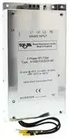


A1000-FIA3300-RE
Power Line Filter, General Purpose, 400 VAC, 300 A, Chassis Mount
- Manufacturer: OMRON INDUSTRIAL AUTOMATION
- Product type:
- SVHC: To Be Advised
- Filter Type: 3 Phase
- No. of Phases: -
- No. of Stages: -
- Product Range: A1000-FIA Series
- Current Rating: 300A
- Voltage Rating: 400VAC
- Filter Mounting: Chassis Mount
- Filter Terminals: Quick Connect
- Filter Applications: General Purpose
- Leakage Current Max: 500mA
- Filter Input Terminals: Terminal Block
- Filter Output Terminals: Terminal Block
| Delivery and price | |
|---|---|
| Units per pack | 1 |
| Price | 1218.0 € |
| Current stock | 10+ |
| Lead time | 30 days |
## **CIMR-L** ## **L1000A** ## **High Performance Vector Control** - High starting torque (200%/0.3 Hz OLV, 200%/0 Hz CLV) - Advanced auto-tuning for IM & PM motors - Light load detection function for UPS - Lift language (Hz, m/s, rpm, levelling speed...) - Rescue operation function - Overshoot and anti-vibration control - Screw-less terminals - Control terminals with memory backup - Built-in braking transistor up to 30 kW unit - Fieldbus communications: CANopen - Safety embedded: ISO/EN13849-1/AC: 2009 PLe (Cat3), IEC EN 61508: 2010 SIL 3, IEC EN 62061: 2005 (SILCL3), IEC EN 61800-5-2: 2007 (SIL 3), IEC EN 61326-3-1: 2008 (EMC-related) and EN81-1/2/20 - Regenerative solutions as option - CE, UL, cUL and TUV ## **Ratings** • 400 V class three-phase 1.5 to 110 kW ## ~~LT~~ **System configuration** **==> picture [478 x 350] intentionally omitted <==** **----- Start of picture text -----**<br> Power<br>Supply<br>©<br>Communications cable with PC<br>MCCB<br>Hl | R ee<br>Vint | ii A RJ-45 / USB USB Cable CX-Drive<br>Adapter CX-One<br>AC Reactor<br>ae | a Remote Operator = LCD Remote ;<br>Extansion Cable Operator<br>Filter<br>D1000 kit*1 24 VDC Control Board Power Supply<br>Communication Option Board<br>Regenerative solution<br>Feedback Speed Option Cards<br>R1000 kit*2<br>L1000A Braking chopper or<br>Braking Resistor<br>Regenerative solution<br>Choke to) Pt! hl<br>DC Reactor<br>Motor *1. The D1000 kit includes a Regenerative DC bus supply unit (D1000), EMC filter and low harmonic filter. If the D1000 kit<br>is purchased, it is not necessary to buy the EMC filter as<br>Output AC Reactor separate item.<br>Ground *2. The R1000 kit includes a Regenerative braking unit (R1000)<br>Jo Pel<br>and current suppression reactor.<br>YASKA WA<br>US B CopyCO M E RR Un it<br>J VOP-181LOCK<br>Copy<br>Verify<br>Read<br>**----- End of picture text -----**<br> **L1000A** 1 ## **Specifications** ## **Type designation** |**400 V class**<br>L1000A series<br>F: SIL3 STO built-in<br>Voltage:<br>4: Three-phase 400 VAC<br>C: European standard<br>specifications<br>AC Drive<br>C I M R - L C 4 F 0 0 0 5 B|**400 V class**<br>L1000A series<br>F: SIL3 STO built-in<br>Voltage:<br>4: Three-phase 400 VAC<br>C: European standard<br>specifications<br>AC Drive<br>C I M R - L C 4 F 0 0 0 5 B|**400 V class**<br>L1000A series<br>F: SIL3 STO built-in<br>Voltage:<br>4: Three-phase 400 VAC<br>C: European standard<br>specifications<br>AC Drive<br>C I M R - L C 4 F 0 0 0 5 B|**400 V class**<br>L1000A series<br>F: SIL3 STO built-in<br>Voltage:<br>4: Three-phase 400 VAC<br>C: European standard<br>specifications<br>AC Drive<br>C I M R - L C 4 F 0 0 0 5 B|**400 V class**<br>L1000A series<br>F: SIL3 STO built-in<br>Voltage:<br>4: Three-phase 400 VAC<br>C: European standard<br>specifications<br>AC Drive<br>C I M R - L C 4 F 0 0 0 5 B|**400 V class**<br>L1000A series<br>F: SIL3 STO built-in<br>Voltage:<br>4: Three-phase 400 VAC<br>C: European standard<br>specifications<br>AC Drive<br>C I M R - L C 4 F 0 0 0 5 B|**400 V class**<br>L1000A series<br>F: SIL3 STO built-in<br>Voltage:<br>4: Three-phase 400 VAC<br>C: European standard<br>specifications<br>AC Drive<br>C I M R - L C 4 F 0 0 0 5 B|**400 V class**<br>L1000A series<br>F: SIL3 STO built-in<br>Voltage:<br>4: Three-phase 400 VAC<br>C: European standard<br>specifications<br>AC Drive<br>C I M R - L C 4 F 0 0 0 5 B|**400 V class**<br>L1000A series<br>F: SIL3 STO built-in<br>Voltage:<br>4: Three-phase 400 VAC<br>C: European standard<br>specifications<br>AC Drive<br>C I M R - L C 4 F 0 0 0 5 B|Version<br>Enclosure type:<br>B: IP20<br>Coating specs:<br>A: Standard<br>Rated output Current<br>Normal Duty<br>0005:<br>4.8 [A]<br>~<br>0216: 216 [A]<br>Option:<br>A3 Brake monitoring/DCP3<br> A C - 9 1 3 0|Version<br>Enclosure type:<br>B: IP20<br>Coating specs:<br>A: Standard<br>Rated output Current<br>Normal Duty<br>0005:<br>4.8 [A]<br>~<br>0216: 216 [A]<br>Option:<br>A3 Brake monitoring/DCP3<br> A C - 9 1 3 0|Version<br>Enclosure type:<br>B: IP20<br>Coating specs:<br>A: Standard<br>Rated output Current<br>Normal Duty<br>0005:<br>4.8 [A]<br>~<br>0216: 216 [A]<br>Option:<br>A3 Brake monitoring/DCP3<br> A C - 9 1 3 0|Version<br>Enclosure type:<br>B: IP20<br>Coating specs:<br>A: Standard<br>Rated output Current<br>Normal Duty<br>0005:<br>4.8 [A]<br>~<br>0216: 216 [A]<br>Option:<br>A3 Brake monitoring/DCP3<br> A C - 9 1 3 0|Version<br>Enclosure type:<br>B: IP20<br>Coating specs:<br>A: Standard<br>Rated output Current<br>Normal Duty<br>0005:<br>4.8 [A]<br>~<br>0216: 216 [A]<br>Option:<br>A3 Brake monitoring/DCP3<br> A C - 9 1 3 0|Version<br>Enclosure type:<br>B: IP20<br>Coating specs:<br>A: Standard<br>Rated output Current<br>Normal Duty<br>0005:<br>4.8 [A]<br>~<br>0216: 216 [A]<br>Option:<br>A3 Brake monitoring/DCP3<br> A C - 9 1 3 0|Version<br>Enclosure type:<br>B: IP20<br>Coating specs:<br>A: Standard<br>Rated output Current<br>Normal Duty<br>0005:<br>4.8 [A]<br>~<br>0216: 216 [A]<br>Option:<br>A3 Brake monitoring/DCP3<br> A C - 9 1 3 0|Version<br>Enclosure type:<br>B: IP20<br>Coating specs:<br>A: Standard<br>Rated output Current<br>Normal Duty<br>0005:<br>4.8 [A]<br>~<br>0216: 216 [A]<br>Option:<br>A3 Brake monitoring/DCP3<br> A C - 9 1 3 0|Version<br>Enclosure type:<br>B: IP20<br>Coating specs:<br>A: Standard<br>Rated output Current<br>Normal Duty<br>0005:<br>4.8 [A]<br>~<br>0216: 216 [A]<br>Option:<br>A3 Brake monitoring/DCP3<br> A C - 9 1 3 0|Version<br>Enclosure type:<br>B: IP20<br>Coating specs:<br>A: Standard<br>Rated output Current<br>Normal Duty<br>0005:<br>4.8 [A]<br>~<br>0216: 216 [A]<br>Option:<br>A3 Brake monitoring/DCP3<br> A C - 9 1 3 0|Version<br>Enclosure type:<br>B: IP20<br>Coating specs:<br>A: Standard<br>Rated output Current<br>Normal Duty<br>0005:<br>4.8 [A]<br>~<br>0216: 216 [A]<br>Option:<br>A3 Brake monitoring/DCP3<br> A C - 9 1 3 0| |---|---|---|---|---|---|---|---|---|---|---|---|---|---|---|---|---|---|---|---| ||||||||||||||||||||| ||||||||||||||||||||| ||||||||||||||||||||| ||||||||||||||||||||| ||||||||||||||||||||| ||||||||||||||||||||| |**Three-phase: CIMR-LC4F@**||**0005**|**0006**|**0009**|**0015**|**0018**|**0024**|**0031**||**0039**||**0045**|**0060**|**0075**|**0091**|**0112**|**0150**|**0180**|**0216**| |**Motor**<br>**kW*1**|**For HD setting**<br>|1.5|2.2|4.0|5.5|7.5|11|15||18.5||22|30|37|45|55|75|90|110| |**Output**<br>**characteristics**|**Inverter capacity kVA*2**|3.7|4.2|7|11.3|13.7|18.3|24||30||34|48|57|69|85|114|137|165| ||**Rated output current (A)**|4.83|5.53|9.23|14.83|183|243|313||393||453|603|753|913|1124|1504|1804|2164| ||**Max. output voltage**|Three-phase 380 to||||||||480 V(proportional to input voltage)|||||||||| ||**Max. output frequency**|200||||||||Hz (user-adjustable)|||||||||| |**Power**<br>**supply**|**Rated input voltage and frequency**|Three-phase 380 to 480 VAC, 50/60 Hz|||||||||||||||||| ||**Allowable voltage fluctuation**|-15% to 10%|||||||||||||||||| ||**Allowable frequency fluctuation**|+5%|||||||||||||||||| ||**Input Current (A)5**|4.4|6|10.4|15|20|29|39||44||49|58|71|86|105|142|170|207| *1. Based on a standard 4-pole motor for maximum applicable motor output. *2. Rated Motor Capacity is calculated with a rated output voltage of 220 V. 3. Carrier frequency can be increased up to 8 kHz while keeping this current rating. Higher carrier frequency settings require derating. 4. Carrier frequency can be increased up to 5 kHz while keeping this current rating. Higher carrier frequency settings require derating. 5. Assumes operation at rated output current. Input current rating varies depending on the power supply transformer, input reactor, wiring conditions, and power supply impedance. Frequency inverters 2 ## **Specifications** ## **Common specifications** |**Model number**<br>**CIMR-LC**|**Model number**<br>**CIMR-LC**|**Specifications**| |---|---|---| |**Control functions**|**Control methods**|V/f control, Open loopvector control, Closed loopvector control, Closed loopvector control for PM| ||**Output frequency range**|0.01 to 200 Hz| ||**Frequency tolerance**|Digital set value: ±0.01% of the max. output frequency (-10 to 40 ºC)| |||Analogue set value: ±0.1% of the max. output frequency (25 ±10 ºC)| ||**Resolution of frequency set value**|Digital set value: 0.01 Hz| |||Analogue inputs: 1/2048 of the maximum output speed setting (11 bitplus sign)| ||**Resolution of output frequency**|0.001 Hz| ||**Frequency set value**|-10 to 10 V(20 k), 0 to 10 V(20 k)| ||**Starting torque**|150%/3Hz(V/f control), 200%/0.3Hz(Open loopvector control), 200%/ 0 r/min(Closed loopvector control)| ||**Speed control range**|1:1500(Closed loopvector control), 1:200(Open loopvector control), 1:40(V/f control)| ||**Speed control accuracy**|±0.2% in Open loopvector control(25 ±10 ºC), 0.02% in Closed loopvector control(25 ±10 ºC)| ||**Speed response**|10 Hz in Open loop vector control (25 ±10 ºC), 100 Hz in Closed loop Vector Control (25 ±10 ºC) (excludes temperature<br>fluctuation whenperformingRotational Auto-Tuning)| ||**Torque limit**|Parameters settingallow separate limits in fourquadrants(available in OLC, CLV, CLV/PM)| ||**Accel/Decel time**|0.00 to 6000.0 s (4 selectable combinations of independent acceleration and deceleration settings, unit changeable to<br>m/s2or ft/s2)| ||**Braking transistor**|Models CIMR-LC2F0008 to 2F0115, 4F0005 to 4F0060 have a built-in brakingtransistor.| ||**V/f characteristics**|Freely programmable| |**Functionality**|**Main control functions**|Inertia Compensation, Position Lock at Start and Stop/Anti-Rollback Function, Overtorque/Undertorque Detection,<br>Torque Limit, Speed Reference, Accel/decel Switch, 5 Zone Jerk Settings, Auto-tuning (stationary and Rotational Motor/<br>Encoder Offset Tuning), Dwell, Cooling Fan on/off Switch, Slip Compensation, Torque Compensation, DC Injection<br>Braking at Start and Stop, MEMOBUS/Modbus Comm (RS-422/485 max, 115.2 kbps), Fault Restart, Removable Ter-<br>minal Block with Parameter Backup Function, Online Tuning, High Frequency Injection, Short Floor, Rescue Operation<br>(Light Load Direction Search Function), Inspection Run, Brake Sequence, Speed related parameters with elevator unit<br>display, etc.| |**Protection functions**|**Motor protection**|Electronic thermal overload relay| ||**Momentary overcurrent protection**|Drive stops when output current exceeds 200% of rated output current| ||**Overload protection**|Drive stops after 60 s at 150% of rated output current(HeavyDutyRating)| ||**Overvoltage protection**|Stops when DC bus exceeds approx. 820V| ||**Undervoltage protection**|Stops when DC bus exceeds approx. 380V| ||**Heatsink overheat protection**|Protected bythermistor| ||**Stall prevention**|Stall Prevention is available duringacceleration, and duringrun| ||**Ground fault**|Electronic circuitprotection| ||**DC Bus charge LED**|Remains lit until DC bus voltage falls below 50 V| |**Ambient conditions**|**Area of use**|Indoor(no corrosivegas, dust, etc.)| ||**Ambient temperature**|-10ºC to 50ºC(open chassis)| ||**Ambient humidity**|95% RH or less(without condensation)| ||**Storage temperature**|-20ºC to 60ºC(short-term temperature duringtransportation)| ||**Altitude**|Upto 1000 m without derating, upto 3000 m with output current and voltage derating| ||**Vibration / shock**|10 to 20 Hz, 9.8 m/s2<br>20 to 55Hz, 5.9 m/s2| |**Safety standard**||Two Safe Disable inputs and 1 EDM output according to ISO/EN13849-1/AC: 2009 PLe (Cat3), IEC EN 61508: 2010 SIL<br>3, IEC EN 62061: 2005 (SILCL3), IEC EN 61800-5-2: 2007 (SIL 3), IEC EN 61326-3-1: 2008 (EMC-related) and EN81-<br>1/2/2. Insulation coordination: class 1<br>**Note:**Time from input open to drive output stopis less than 1 ms.| |**Protection design**||IP20 enclosure| **L1000A** 3 ## omrRON ~~PO~~ **Dimensions** ## **Enclosed Panel [IP20]** **==> picture [510 x 625] intentionally omitted <==** **----- Start of picture text -----**<br> W1 4-d W1 4-d t2<br>t1<br>W D1<br>Ly ah D finn om D 1<br>—o Max 10 L—— W Max 10 a D<br>Figure 1 Figure 2<br>Max. applicable Inverter model CT Dimensions in mm<br>Voltage class motor output kW CIMR-LC@ Figure W H D W1 H0 H1 H2 H3 D1 t1 t2 d Weight<br>eee (kg)<br>Three-phase 1.5 4F0005 1 140 260 147 122 - 248 6 - 38 5 - M5 3.2<br>es ee | | | | |<br>400 V 2.2 4F0006 164 55 3.4<br>4.0 4F0009 3.5<br>5.5 4F0015 167 3.9<br>ee eee =<br>=n 7.5 4F0018 |<br>—— 11 4F0024 180 300 a 160 284 8 = 5.4<br>15 4F0031 187 75 5.7<br>ee 18.5 4F0039 220 350 197 192 335 78 M6 — 8.3<br>22 4F0045 2 254 465 258 195 400 385 7.5 65 100 2.3 2.3 23<br>30 4F0060 279 515 220 450 435 27<br>37 4F0075 329 630 260 510 495 120 105 39<br>45 4F0091<br>ee eee<br>55 4F0112 283 550 535 80 110 43<br>=e 75 4F0150 — 45<br>90 4F0180 450 705 330 325 705 680 12.5 163 130 3.2 3.2 M10 85<br>110 4F0216 500 800 350 370 800 773 13 238 4.5 4.5 M12 103<br>aee ee -—}—}a ee+ + +++ ee+--+ee ee ee<br>Schaffner filters<br>D C<br>H B<br>A<br>E<br>G<br>LE =i 3 1<br>Figure 2<br>F<br>a<br>Figure 1<br>Bookform filters Fig Dimensions Weight<br>| A B C D E F G H I L (kg)<br>400 V 3G3RV-PFI3010-SE 1 330 141 46 281 313 115 5.5 M4 23 M5 1.2<br>fC LSE<br>3G3RV-PFI3018-SE 330 141 46 281 313 115 5.5 M4 23 M5 1.3<br>fs | [ [| | | f[ Jf [ ff |<br>i 3G3RV-PFI3035-SE a 355 206 se 50 Gs 302 336 es 175 6.5 M5 25 M6 2.2<br>3G3RV-PFI3060-SE 408 236 65 355 390 205 6.5 M6 32.5 M6 4<br>Po aeeea ee ee es ee<br>3G3RV-PFI3100-SE 2 326 150 90 240 255 65 6.5 M10 - - 4.5<br>3G3RV-PFI3170-SE 451 170 120 350 365 102 6.5 M10 - - 6.0<br>SaaSPo 3G3RV-PFI3200-SE | 518 240 ft 130 fe 480 498 90 8.3 M10 - - 11.7<br>H1 H0<br>H1 H H<br>H2<br>H3<br>H2<br>**----- End of picture text -----**<br> ## **Schaffner filters** Frequency inverters 4 ## **Rasmi filters** |Fig 1|H|H|dri<br>utput<br>exes|W<br>Y<br>L<br>Fig 2<br>ve mounts<br>W<br>Y<br>X|W<br>Y<br>L<br>Fig 2<br>ve mounts<br>W<br>Y<br>X|W<br>Y<br>L<br>Fig 2<br>ve mounts<br>W<br>Y<br>X|H<br>X<br>L<br>Fig 3|H<br>X<br>L<br>Fig 3|H<br>X<br>L<br>Fig 3|H<br>X<br>L<br>Fig 3|H<br>X<br>L<br>Fig 3|H<br>X<br>L<br>Fig 3|||| |---|---|---|---|---|---|---|---|---|---|---|---|---|---|---|---| ||||||||||||||H|W|| ||||||||||||||||| ||L||||||||||||||| ||||||||||||||||| ||o<br>fl||||||||||||||| ||||||||||||||||| |||||**Flat filters**||**Figure**|**Dimensions**<br>**L**<br>**W**<br>**H**<br>**X**<br>**Y**|||||||**Weight**<br>**(kg)**|| |||||||||**W**|**H**|**X**|**Y**||**Fixing**||| ||||400 V|A100<br>A100<br>A100<br>A10<br>A10<br>A10<br>A10|0-FIA3024-RE*1|1|306<br>357<br>415|150|5|2<br>290|122||M5|2.0|| ||||||0-FIA3044-RE1|||182|6|2<br>330|160||M5|2.8|| ||||||0-FIA3052-RE1|||220|6|2<br>380|192||M6|3.9|| ||||||00-FIA3071-RE|2|329<br>379<br>429|80|22|0<br>314|55||M6|5.3|| ||||||00-FIA3105-RE|||90|22|0<br>364|65||M6|6.5|| ||||||00-FIA3170-RE|||110|24|0<br>414|80||M6|9|| ||||||00-FIA3300-RE|3|300|260|13|5<br>120|235||M10|13.2|| ||*1.||Footprint filter||||||||||||| **Remote LCD operator** **==> picture [284 x 173] intentionally omitted <==** **----- Start of picture text -----**<br> Installation holes<br>12.2 1.6 (0.06) (2-M3 screws, depth 5 (0.19))<br>(0.48)<br><1><br>60 (2.36) 7.9 44 (1.73)<br>(0.31)<br>minimum 50 (1.96) Unit : mm (in)<br>)(3.5490 )(3.0778<br>15<br> (0.59)<br>**----- End of picture text -----**<br> ## **Chokes** ||||||||||||| |---|---|---|---|---|---|---|---|---|---|---|---| |**Chokes**||**or**<br><br>**Dimensions**<br>**Weight**<br>**(kg)**<br>**L**<br>**W**<br>**H**<br>**X**<br>**Y**<br>**m**<br>2<br>85<br>22<br>46<br>90<br>-<br>5<br>0.1<br>5<br>106<br>24<br>62<br>70<br>-<br>5<br>0.2<br>5<br>150<br>50<br>112<br>125<br>30<br>5<br>0.7<br>5<br>200<br>65<br>170<br>180<br>45<br>6<br>1.7<br>H<br>Y<br>W||||||X|||Øm| |||||||||L<br>Ød|||| |**Description**|**D**<br>**diameter**<br>**Mot**<br>**kW**|**or**<br><br>**Dimensions**<br>**L**<br>**W**<br>**H**<br>**X**<br>**Y**<br>**m**||||**Weight**<br>**(kg)**|Y<br>||||| ||||||||||||| ||||**H**|**X**<br>**Y**|**m**||||||| |AX-FER2102-RE|21<br>< 2.|2<br>85<br>22|46<br>|90<br>-|5|0.1|||||| |AX-FER2815-RE|28.5<br>< 1|5<br>106<br>24|62<br>|70<br>-|5|0.2|H||||| |AX-FER5045-RE|50<br>< 4|5<br>150<br>50|112<br>1|25<br>30|5|0.7|||||| |AX-FER6055-RE|60<br>> 4|5<br>200<br>65|170<br>1|80<br>45|6|1.7|||||| ||||||||||||| **L1000A** 5 ## **D1000 kit - DC Supply with Regenerative Active Front End** ## **Regenerative DC bus supply unit (D1000)** **==> picture [422 x 121] intentionally omitted <==** **----- Start of picture text -----**<br> W1 d W1 d W1 d<br>H1 H H1 H H1 H<br>W H2 D D1 W H2 D D1 W H2 D D1<br>Figure 1 Figure 2 Figure 3<br>**----- End of picture text -----**<br> |**Voltage**<br>**class**|**Model**<br>**CIMR-DC@**|**Figure**|**IP**<br>**W**|**Dimensions in mm**|**Dimensions in mm**|**Dimensions in mm**|**Dimensions in mm**|**Dimensions in mm**|||| |---|---|---|---|---|---|---|---|---|---|---|---| |||||**H**|**D**|**W1**|**H1**|**H2**|**D1**|**d**|**Weight kg**| |Three-phase<br>400 V|4A0005<br>4A0010<br>4A0020|1|20<br>180<br>220|300|187|160|284|8|75|M5|5| |||||365|197|192|335||78|M6|8| ||4A0030<br>4A0040|2|00<br>275<br>325<br>500|450|258|220|435|7.5|100||21| ||4A0060<br>4A0100<br>4A0130|3||550|283|260|535||110||34| ||||||||||||36| |||||800|350|370|773|13|130|M12|85| ## **EMC filter** **==> picture [388 x 77] intentionally omitted <==** **----- Start of picture text -----**<br> W<br>Marking<br>H D LINE LOAD H D<br>Figure 1 W Figure 2<br>**----- End of picture text -----**<br> |**Model**|**Figure**|**Dimensions in mm**|**Dimensions in mm**|**Dimensions in mm**|**Dimensions in mm**| |---|---|---|---|---|---| |||**W**|**H**|**D**|**Weight kg**| |B84143A0020R106|1|386|200|202|0.6| |B84143A0035R106||426|250|322|0.9| |B84143A0065R106||436|310|432|1.9| |B84143B0180S080||200|170|110|5.0| |B84143B0400S080|2|290|190|116|7.5| Frequency inverters 6 ## **Low harmonic filter** **==> picture [484 x 279] intentionally omitted <==** **----- Start of picture text -----**<br> W<br>H<br>D d<br>Figure 1<br>W H<br>W H<br>W H<br>d<br>D d d D<br>D<br>Figure 2a Figure 2b Figure 2c<br>W H W<br>H<br>D<br>D<br>**----- End of picture text -----**<br> **==> picture [220 x 7] intentionally omitted <==** **----- Start of picture text -----**<br> Figure 3a Figure 3b<br>**----- End of picture text -----**<br> |**Model**|**Component**|**Figure**||**Dimensions in mm**|**Dimensions in mm**|**Dimensions in mm**|| |---|---|---|---|---|---|---|---| ||||**W**|**H**|**D**|**d(diamet**|**er)**<br>**Weight kg**| |B84143G0008R176||1|386|176 ±5|200|9|9<br>18<br>28<br>37<br>64| |B84143G0016R176|||426|234 ±5<br>236 ±5|320||| |B84143G0030R176|||||||| |B84143G0043R176|||436|286 ±5|430||| |B84143G0058R176|||||||| |B84143G0086R176|Harmonic filter|2a|265|288 ±5|240|9|20| ||10% choke|2b|149|max. 390|300|15 x 25|<br>55| |B84143G0145R176|Harmonic filter|2a|328|303 ±5|240|9|30| ||10% choke|2c|max. 390|max. 405|max. 365|15 x 25|<br>69| |B84143G0210S176|Harmonic filter|3a|206 ±3|438|300|-|39| ||10% choke|3b|max. 400|max. 445|max. 420|-|98| **L1000A** 7 ## **R1000 kit - Regenerative Braking unit** ## **Regenerative Braking unit (R1000)** **==> picture [426 x 313] intentionally omitted <==** **----- Start of picture text -----**<br> W1 4-d W1 4-d<br>t1 D1 t1<br>W D D1 W D<br>Figure 1 Figure 2<br>W1 4-d W1 4-d<br>t1 t1<br>t1 t1<br>D1 D1<br>Max 10 W Max 10 D Max 8 W Max 8 D<br>Figure 3 Figure 4<br>1.5 1.5<br>H1 H H1 H0 H<br>H2 H2 H3<br>H1 H<br>H1 H<br>H2 H2<br>**----- End of picture text -----**<br> |**Voltage**<br>**class**|**Model**<br>**CIMR-RC@**|**Figure**<br>**IP**|**Dimensi**|**Dimensi**|**Dimensi**|**ons in mm**|||| |---|---|---|---|---|---|---|---|---|---| ||||**W**<br>**H**<br>**D**|**W1**|**H0**<br>**H1**|**H2**<br>**H3**<br>**D**|**1**<br>**t1**|**d**|**Weight kg**| |Three-phase<br>400 V|4A03P5|1<br>20<br>2|140<br>260<br>167|122|-<br>248<br>284|6<br>-<br>5<br>8<br>7<br>15<br>7|5<br>5<br>5<br>8|M5|4| ||4A0005||||||||| ||4A0007||||||||| ||4A0010||180<br>300<br>187|160|||||5| ||4A0014||||||||| ||4A0017||220<br>365<br>197|192|350<br>355|||M6|8| ||4A0020||||||||| ||4A0028||||||||| ||4A0035|3<br>00<br>4|275<br>450<br>258|220|-<br>435<br>535<br>680|7.5<br>-<br>1<br>1<br>13<br>1|00<br>2.3<br>10|M6|20| ||4A0043||||||||| ||4A0053||325<br>550<br>283|260|||||33| ||4A0073||||||||| ||4A0105||450<br>705<br>330|325|||30<br>3.2|M10|62| Frequency inverters 8 ## **Current suppression reactor** **==> picture [464 x 452] intentionally omitted <==** **----- Start of picture text -----**<br> earth screw M5x10<br>earth terminal 6.3x0.8 4 mm terminal2 (with lockwasher and washer) 16 mm terminal2<br>A B A B1<br>B<br>id ld |<br>Figure 1 Figure 2<br>earth screw M5x10 35 mm terminal2<br>(with lockwasher and washer)<br>a A | - B<br>A B1<br>B<br>Figure 3 Figure 4<br>earth connector<br>U1 V1 W1<br>U2 V2 W2<br>ail! |b<br>A B1<br>B<br>C C<br>C<br>C<br>D<br>C<br>**----- End of picture text -----**<br> Figure 5 |**Model**<br>~~=~~|**Figure**<br>~~=~~|**Dimensions in mm**<br>~~——————————————~~|**Dimensions in mm**<br>~~——————————————~~|**Dimensions in mm**<br>~~——————————————~~|**Dimensions in mm**<br>~~——————————————~~|**Dimensions in mm**<br>~~——————————————~~|**Dimensions in mm**<br>~~——————————————~~| |---|---|---|---|---|---|---|---| |||**A**<br>~~——————~~|**B**<br>~~——————~~|**B1**<br>~~————————————~~|**C**<br>~~————~~|**D**<br>~~——————~~|**Weight kg**| |B1509105<br>~~=~~<br>~~fe~~|1<br>~~= ~~<br>~~fe~~<br>~~eea ee~~|max. 78<br> ~~——————~~<br>~~fe~~|63<br>~~——————~~<br>~~fe~~|-<br>~~————————————~~<br>~~fe~~<br>~~ee~~|102<br>~~————~~<br>~~fe~~|-<br>~~——————~~<br>~~fe~~<br>~~ee~~|0.85<br>~~fe~~| |B1509106<br>~~fe~~||max. 96<br>~~fe~~<br>~~ee~~|60<br>~~fe~~<br>~~ee~~||118<br>~~fe~~<br>~~ee~~||1.31<br>~~fe~~| |B1509107<br>~~fe~~<br>~~ee~~|||||||1.32<br>~~fe~~<br>~~ee~~| |B1509108<br>~~ee~~|2<br>~~eea ee~~|120<br>~~ee~~|max. 90<br>~~ee~~|85<br>~~ee~~|150<br>~~ee~~|-<br>~~ee~~|1.9<br>~~ee~~| |B1509109<br>~~ee~~|||||||1.93<br>~~ee~~| |B1509110<br>~~ee~~<br>~~Rs~~<br>~~ee~~|3<br>~~eea ee~~<br>~~RsGD~~<br>~~ee~~|155<br>~~ee~~<br>~~GD~~|max. 102<br>~~ee~~<br>~~GDQO~~|95<br>~~ee~~<br>~~QQ~~|195<br>~~ee~~<br>~~QQ~~|-<br>~~ee~~<br>~~QQ~~|3.8<br>~~ee~~<br>~~QQ~~| |B1504118<br>~~ee~~<br>~~Rs~~<br>~~ee~~|4<br>~~ee a ee~~<br>~~RsGD~~<br>~~ee~~|155<br>~~ee~~<br>~~GD~~|95<br>~~ee~~<br>~~GDQO~~|-<br>~~ee~~<br>~~QQ~~|175<br>~~ee~~<br>~~QQ~~|-<br>~~ee~~<br>~~QQ~~|4.0<br>~~ee~~<br>~~QQ~~| |B1509111<br>~~Rs~~<br>~~ee~~|3<br>~~Rs GD~~<br>~~ee~~|155<br>~~GD~~|max. 102<br>110<br>~~GDQO ~~|95<br>-<br> ~~QQ~~|195<br>~~QQ~~|-<br>~~QQ~~|4.43<br>~~QQ~~| |B1509112<br>~~ee~~|||||||5.95| |B1509113<br>~~ee~~<br>~~EEE~~|5<br>~~ee~~<br>~~EEE~~|185<br>~~EEE~~|max. 125<br>max. 140<br>~~EEE~~|102<br>122<br>~~EEE~~|160<br>~~EEE~~|3<br>~~EEE~~|6.9<br>~~EEE~~| |B1509114<br>~~EEE~~|||||||10.8<br>~~EEE~~| **L1000A** 9 **==> picture [441 x 326] intentionally omitted <==** **----- Start of picture text -----**<br> omRON<br>Braking units B<br>S<br>Dimensions<br>Reference<br>AX-BCR4035090-TE 130 B 64.5 B1 205 H 193 H1 208 T S 6 C HO PP ERBC...<br>Ss AX-BCR4070130-TE hi g OVERCURRENTACTIVEPOWER<br>DANGERHIGH VOLTAGE !<br>B1 T<br>Resistor<br>Fig 1 Fig 2<br>Fig 3 Fig 4<br>H H1<br>BUSS BUSS+ R R<br>**----- End of picture text -----**<br> **Dimensions Weight Type Fig. L H M I T G N (kg)** ~~eeGGPe~~ AX-REM00K9120-IEAX-REM01K9040-IE 21 ~~rePO~~ 365200 ~~es~~ 7361 ~~eee~~ 105100 ~~ees~~ 74.5350 ~~OOee~~ 21670 ~~ee~~ 40- ~~ee~~ 2301.414 AX-REM03K5035-IE 3 365 100 240 350 210 - - 8 AX-REM03K5025-IE ~~————~~ AX-REM19K0020-IE 4 ~~ft~~ 206 ~~rE~~ 350 ~~rd~~ 140 190 50 - - 8.1 AX-REM19K0030-IE ~~Po————j;~~ AX-REM38K0012-IE ~~Lta~~ 306 350 ~~tTse~~ 140 ~~ft~~ 290 ~~ee~~ 50 ~~Pr~~ - - 14.5 Frequency inverters 10 ## ~~LO~~ **Installation** ## **Standard connections** **==> picture [504 x 491] intentionally omitted <==** **----- Start of picture text -----**<br> Terminals -, +1, +2, B1, B2 are for connecting options. Never connect power supply lines to U DC reactor(option) X Thermal relay(option)<br>these terminals Jumper Braking resistor<br>(option)<br> 2 1 B1 B2<br>U Motor<br>Main Main Circuit U/T1<br>Switch Fuse V/T2 V M<br>Three-phase power supply380 to 480 Vac S/L2R/L1 EMC Filter R/L1S/L2 L1000A W/T3 W<br>50/60 Hz T/L3 T/L3 Control Circuit ee hel<br>——. — © C....._) @ | \ NAcc Shielded<br>Up command / Stop S1 Option card connectors Ground Cable<br>CN5-C<br>Down command / Stop S2<br>CN5-B<br>Nominal Speed S3<br>CN5-A<br>Inspection Operation S4<br>Terminal board<br>jumper and switch<br>Intermediate Speed 1 S5<br>Multi-function Off On DIP Switch S2Term. Res. On/Off<br>digtial inputs Leveling Speed S6<br>(default setting) Jumper S3<br>Not Used S7 H1, H2 Sink/Source Sel.<br>Not Used S8<br>SN<br>MA Fault relay output<br>Sink / Source mode selection wire link SC MB 250 Vac, max. 1 A30 Vdc, max 1 A<br>(default: Sink) SP MC (min. 5 Vdc, 10 mA)<br>- +24 V “]<br>M1 Multi-function relay output (Brake Control)<br>Shield ground terminal M2 250 Vac, max. 1 A30 Vdc, max 1 A<br>(min. 5 Vdc, 10 mA)<br>2 k : V Power supply +10.5 Vdc, max. 20 mA MM34 | Multi-function relay output (Output Contactor Control)250 Vac, max. 1 A30 Vdc, max 1 A<br>Multi-function I o A1 Analog Input 1 (Speed Bias)-10 to +10 Vdc (20 k) 1 (min. 5 Vdc, 10 mA)<br>analog inputs M5 Multi-function relay output (Drive Ready)<br>A2 Analog Input 2 (Not used)-10 to +10 Vdc (20 k) M6 250 Vac, max. 1 A30 Vdc, max 1 A<br>(min. 5 Vdc, 10 mA)<br>= AC<br>0 V P1<br>V Power supply, -10.5 Vdc, max. 20 mA Photo Coupler 1<br>C1 (During Frequency Output) Digital output<br>Termination resistor(120 , 1/2 W) P2 5 to 48 Vdc2 to 50 mA<br>Photo Coupler 2 (default setting)<br>DIP C2 (not used)<br>R Switch S2<br>R<br>MEMOBUS/Modbus comm. RS485/422max. 115.2 kBps SS FM FM Multi-function analog output 1(Output Speed)-10 to +10 Vdc (2mA)<br>IG<br>AM<br>AC AM Multi-function analog output 2(Output Current)<br>H1 0 V -10 to +10 Vdc (2mA)<br>H2<br>E (G)<br>Safe Disable inputs<br>shielded line<br>DM <br>HC DM EDM (Safety Electronic Device Monitor) twisted-pair shielded line<br>@) control circuit terminal<br>main circuit terminal<br>**----- End of picture text -----**<br> ## **Main circuit** |**Terminal**<br>~~es~~<br>~~es~~|**Name**|**Function (signal level)**| |---|---|---| |**R/L1, S/L2, T/L3**<br>~~es~~<br>~~es~~<br>~~ee~~|Main circuit power supply input|Used to connect line power to the drive| |**U/T1, V/T2, W/T3**<br>~~es~~<br>~~ee~~<br>~~ns~~|Inverter output|Used to connect the motor| |**B1, B2**<br>~~ee~~<br>~~ns~~<br>~~ns~~|Braking resistor connection|Available for connecting a braking resistor or the braking resistor unit option| |**+2, +1**<br>~~ns~~<br>~~ns~~<br>~~ns~~|DC reactor connection|Remove the short bar between +2 and +1 when connecting DC reactor (option)| |**+1, –**<br>~~ns~~<br>~~ns~~<br>~~ns~~|DC power supply input|For power supply input (+1: positive electrode; – : negative electrode)| |**+3**<br>~~ns~~<br>~~ns~~<br>~~ee~~|Braking Unit<br>~~rs~~|Connection for Braking Unit between terminals +3 and –<br>~~rs~~| |~~ns~~<br>~~ee~~|Grounding<br>~~rs~~|For grounding (grounding should conform to the local grounding code)<br>~~rs~~| **L1000A** 11 ## **Control Circuit** |**Type**|**No.**|**Signal name**|**Function**|**Signal level**| |---|---|---|---|---| |**Digital input signals**|**S1**|Up Command|Closed: UP, Open: Stop|24 VDC, 8 mA<br>photocoupler<br>insulation| ||**S2**|Down Command|Closed: Down, Open: Stop|| ||**S3**|Multi-function input selection 3|Nominal speed|| ||**S4**|Multi-function input selection 4|Inspection Operation|| ||**S5**|Multi-function input selection 5|Intermediate Speed 1|| ||**S6**|Multi-function input selection 6|Leveling Speed|| ||**S7**|Multi-function input selection 7|Not used|| ||**S8**|Multi-function input selection 8|Not used|| ||**SC**|Multi-function input Common|Common for control signal|| ||**SN**|0 V|Photocoupler, 24 VDC, 8mA<br>Use the wire link between terminals SC and SN or between SC and SP to select sinking or sourcing,<br>and to select the power supply.|| ||**SP**|+24 VDC||| |**Analog input signals**|**+V**|Power Supply for analog inputs|+10.5 V (allowable max current 20 mA)|| ||**–V**|Power Supply for analog inputs|–10.5 V (allowable max current 20 mA)|| ||**A1**|Multi-function analogue input 1|Speed reference bias -10 to +10 VDC, 0 to +10 VDC (20 k|| ||**A2**|Multi-function analogue input 2|Not used -10 to +10 VDC, 0 to +10 VDC (20 k|| ||**AC**|Analog input common|0 V|| ||**E(G)**|Ground for shielded lines and option cards||| |**Safety input**|**HC**|Safe Disable function common|Common for the Safe Disable function|| ||**H1**|Safe Disable input 1|24 VDC, 8mA (3.3 k)<br>Off time of at least 1ms<br>Set the S3 jumper to select sinking or sourcing, and to select the power supply<br>One of both open: Drive output disabled<br>Both closed: Normal operation|| ||**H2**|Safe Disable input 2||| |**Safety**<br>**monitor**<br>**output**|**DM+**|Safety monitor output|Outputs status of Safe Disable function. Closed when both Safe Disable chan-<br>nels are closed|48 VDC, 50mA or less| ||**DM–**|Safety monitor output common||| |**Fault relay**|**MA**|NO contact output|Factory setting: "fault"|Contact capacity<br>250 VAC,<br>10mA to 1A<br>30 VDC, 10mA to 1A<br>Minimum load: 5VDC<br>10mA| ||**MB**|NC output||| ||**MC**|Fault output common||| |**Multi-function**<br>**relay output**|**M1**|Multi-function relay output 1|Factory setting: Brake release command|| ||**M2**|||| ||**M3**|Multi-function relay output 2|Factory setting: Output contactor close command|| ||**M4**|||| ||**M5**|Multi-function relay output 3|Factory setting: Drive ready|| ||**M6**|||| |**Multi-function**<br>**photocoupler**<br>**output**|**P1**|Photocoupler output 1|Factory setting: During Frequency output)|48 VDC, 2 to 50mA| ||**C1**|||| ||**P2**|Photocoupler output 2|Factory setting: Not Used / Through Mode|| ||**C2**|||| |**Analog output**<br>**signals**|**FM**|Multi-function analog monitor (1)|Factory setting: Output Speed|–10 to 10 V ±5%,<br>(2 mA or less)<br>0 to 10 V<br>4 - 20 mA| ||**AM**|Multi-function analog monitor (2)|Factory setting: Output Current|| ||**AC**|Analog monitor common|0 V|| |**RS-485/422**|**R+**|Communication input (+)|For MEMOBUS/Modbus communication:<br>Use an RS-485 or RS-422 cable to connect the drive|RS-485/422<br>MEMOBUS/Modbus<br>communication proto-<br>col: 115.2 kbps max.| ||**R–**|Communication input (–)||| ||**S+**|Communication output (+)||| ||**S–**|Communication output (–)||| ||**IG**|Shield ground|0V|| Frequency inverters 12 ## **Inverter heat loss** ## **Three-phase 400 V class** |**Model Number**<br>**CIMR-LC@**|**Heavy Duty**|**Heavy Duty**|**Heavy Duty**|| |---|---|---|---|---| ||**Rated Amps (A)**|**Heatsink Loss**<br>**(W)**|**Interior Unit**<br>**Loss(W)**|**Total Loss (W)**| |**4F0005**|4.8|37|49|87| |**4F0006**|5.5|48|53|101| |**4F0009**|9.2|68.5|61|129.5| |**4F0015**|14.8|135.4|85.7|221.1| |**4F0018**|18.0|149.9|97|246.9| |**4F0024**|24|208|115.1|323.2| |**4F0031**|31|262.6|140.8|403.4| |**4F0039**|39|329.8|179.4|509.2| |**4F0045**|45|348.5|169.6|518.1| |**4F0060**|60|484.1|217.2|701.3| |**4F0075**|75|563.4|254|817.4| |**4F0091**|91|722.6|299|1021.7| |**4F0112**|112|908.2|416.4|1324.6| |**4F0150**|150|1340.3|580.1|1920.3| |**4F0180**|180|1771.4|541|2312.5| |**4F0216**|216|2360.2|715.1|3075.3| ## **Connections for braking unit and braking resistor** **==> picture [341 x 164] intentionally omitted <==** **----- Start of picture text -----**<br> Thermal<br>relay Braking resistor Overheat ContactBraking Resistor<br>Power (Thermal Relay Trip Contact)<br>supply MCCB MC R/L1 [B1] B2 + 3 −<br>1 2 Braking<br>S/L2 U/T1 Resistor<br>T/L3 V/T2 Motor P B Unit<br>W/T3<br>THRX OFF ON MC L1000A − + + 0 − 0<br>MC SA L1000A MASTER<br>THRX<br>Thermal relay switch forexternal braking resistorSA 1 SLAVE +155<br>MC TRX 6<br>2<br>SA<br>TRX<br>FLT-A FLT-B Braking Unit 1<br>Fault contact 3 4<br>Cooling Fin Overheat Contact<br>(Thermoswitch Contact)<br>Level Detect or<br>**----- End of picture text -----**<br> **Input AC reactor** ||||AC reactor|||L1000A|| |---|---|---|---|---|---|---|---| |Power supply|MCCB||U|X|R/L1||| ||||V|Y|S/L2||| ||||W|Z|T/L3||| ||||||||| ||||**400 V class**||||| |**Max. applicable**|||**Current value**||**Inductance**||| |**motor output kW**|||**A**|||**mH**|| |1.5|||5|||7.7|| |2.2 to 4.0|||10|||3.5|| |5.5 to 7.5|||17|||1.3|| |11.0 to 15.0|||33.5|||0.74|| |18.5 to 22.0|||50|||0.36|| |30.0 to 37.0|||78|||0.29|| |45.0 to 55.0|||115|||0.19|| |75.0 to 90.0|||185|||0.11|| |110.0|||270|||0.07|| **L1000A** 13 ## **DC reactor** **==> picture [256 x 224] intentionally omitted <==** **----- Start of picture text -----**<br> L1000A<br>Power<br>supply MCCB R/L1<br>S/L2<br>T/L3<br>+1 +2<br>DC reactor<br>400 V class<br>Max. applicable Current value Inductance<br> motor output kW A mH<br>1.5 4.7 14<br>2.2 6.9 10.1<br>4.0 11.6 6.4<br>5.5 16.7 4.41<br>7.5 21.9 3.35<br>11.0 30.7 2.33<br>15.0 43.0 1.75<br>18.5 64.4 1.2<br>22.0 to 110.0 Built-in<br>**----- End of picture text -----**<br> ## **Safety System** - L1000A provides Safe Torque Off (STO) functional safety in compliance with ISO/EN13849-1/AC: 2009 PLe (Cat3), IEC EN 61508: 2010 SIL 3, IEC EN 62061: 2005 (SILCL3), IEC EN 61800-5-2: 2007 (SIL 3), IEC EN 61326-3-1: 2008 (EMC-related) and EN81-1/2/20. - An External Device Monitor (EDM) function has also been added to monitor the safety status of the drive. **==> picture [271 x 257] intentionally omitted <==** **----- Start of picture text -----**<br> Safety Chain<br>Circuit<br>Elevator Controller<br>Contactor Control Contactor Check<br>Command (Restart Permission)<br>K01<br>K1<br>K2<br>H1 H2 HC Up/Down;<br>Safe Disable Speed selection...<br>Safe Disable Monitor<br>(H2- = 58)<br>CIMR-LC4Fxxxx<br>M<br>**----- End of picture text -----**<br> Frequency inverters 14 ## **D1000 kit - DC Supply with Regenerative Active Front End system** **==> picture [314 x 341] intentionally omitted <==** **----- Start of picture text -----**<br> Power<br>supply<br>D1000 kit<br>EMC filter<br>Low harmonic<br>filter<br>Regenerative DC<br>bus supply unit<br>(D1000)<br>1 ~ n<br>1 2 3 n<br>L1000A<br>Motor<br>**----- End of picture text -----**<br> ## **Regenerative DC bus supply unit (D1000)** |**Reference: CIMR-DC@**|**4A0005**|**4A0010**|**4A0020**|**4A0030**|**4A0040**|**4A0060**|**4A0100**|**4A0130**| |---|---|---|---|---|---|---|---|---| |Max. applicable motor capacity<br>|(kW)<br>3.7|7.5|15|22|30|45|75|110| |Rated output capacity (kW)*1|5|10|20|30|40|60|100|130| |Rated input current AC(A)|8|16|30|43|58|86|145|210| |Rated output current DC(A)|8|15|30|45|61|91|152|197| |Rated input voltage|3-phase 380 to 480 VAC|||||||| |Rated output voltage|660 VDC|||||||| |Rated frequency|50/60 Hz|||||||| |Inputpower factor|> 0.99|||||||| |Carrier frequency|6||||||4|| |Degree of protection|IP20 (CIMR-DC4A0005 to CIMR-DC4A0020 models)<br>IP00(CIMR-DC4A0030 to CIMR-DC4A0130 models)|||||||| |Ambient humidity|95% RH or less(without condensation)|||||||| |Storage temperature|-20 to 60ºC|||||||| |Ambient temperature|-10 to 50ºC|||||||| *1. Rated output capacity is calculated with a rated input voltage of 400 V. ## **EMC filter** |**Reference: B84143@**|**A0020R106**|**A0035R106**|**A0065R106**|**B0180S080**|**B0400S080**| |---|---|---|---|---|---| |Rated current(A)|20|35|65|180|400| |Leakage current(mA)|3.1|3.4|3.4|< 21|< 21| |Rated voltage<br>30|0/520 VAC||||| |Rated frequency<br>50|/60 Hz||||| |Rated temperature<br>50|ºC||||| |Degree ofprotection<br>IP2|0||||| ## **Low harmonic filter** |**Reference: B84143G@**|**0008R176**<br>**001**|**6R176**|**0030R1**|**76**<br>**0043R176**|**0058R176**|**0086R176**|**0145R176**|**0210S176**| |---|---|---|---|---|---|---|---|---| |Rated current(A)<br>|8|16|30|43|58|86|145|210| |Heat loss(W)*1|75<br>|140|165|240|260|300|515|665| |Rated voltage<br>30|5/530 VAC|||||||| |Rated frequency<br>50|/60 Hz|||||||| |Rated temperature<br>50|ºC|||||||| |Degree ofprotection<br>IP0|0|||||||| *1. Heat loss at nominal current and 20ºC winding temperature with harmonics. **L1000A** 15 ## **R1000 kit - Regenerative Braking unit system** **==> picture [272 x 231] intentionally omitted <==** **----- Start of picture text -----**<br> Power<br>supply<br>AC input<br>reactor<br>R1000 kit<br>Current suppression<br>reactor<br>Regeneretive<br>L1000A<br>braking unit (R1000)<br>Motor<br>**----- End of picture text -----**<br> ## **Regenerative Braking unit (R1000)** |**Reference:**<br>**CIMR-RC@**<br>**4A03**|**P5**<br>**4A0005**|**4A000**|**7**<br>**4A0010**|**4A0014**|**4A0017**|**4A0020**|**4A0028**|**4A0035**|**4A0043**|**4A0053**|**4A0073**|**4A0105**| |---|---|---|---|---|---|---|---|---|---|---|---|---| |Max. applicable<br>motor capacity (kW)<br>3.|7<br>5.5|7.5|11|15|18.5|22|30|37|45|55|75|110| |Rated output<br>capacity (kW)*1<br>3.|5<br>5|7|10|14|17|20|28|35|43|53|73|105| |Rated input current<br>AC(A)<br>5|8|11|16|22|27|32|43|54|66|81|110|161| |Rated output current<br>DC(A)<br>7|11|15|22|30|36|43|58|73|89|109|149|217| |Rated input voltage<br>3-pha|se 380 to 480 VAC|||||||||||| |Rated frequency<br>50/60|Hz|||||||||||| |Power factor<br>> 0.9|at full load|||||||||||| |Degree of protection IP20 (<br>IP00(|CIMR-RC4A03P5 to CIMR-RC4A0028 models)<br>CIMR-RC4A0035 to CIMR-RC4A0105 models)|||||||||||| |Ambient humidity<br>95% R|H or less(without condensation)|||||||||||| |Storage temperature -20 to|60ºC|||||||||||| |Ambient temperature -10 to|50ºC|||||||||||| *1. Rated output capacity is calculated with a rated input voltage of 400 V. ## **Current suppression reactor** |**Reference: B150@**|**9105**|**9106**|**9107**|**9108**|**9109**|**9110**|**4118**|**9111**|**9112**|**9113**|**9114**| |---|---|---|---|---|---|---|---|---|---|---|---| |Rated current(A)|7.5|10|15|25|30|40|50|60|75|100|161| |Inductance(mH)|1.2|0.6|0.4|0.3|0.2|0.15|0.12|0.1|0.08|0.06|0.04| |Heat loss(W)|21|19|23|36|33|40|46|56|81|72|95| Frequency inverters 16 ## **Ordering information** **==> picture [511 x 370] intentionally omitted <==** **----- Start of picture text -----**<br> Power<br>Supply C<br>Communications cable with PC<br>MCCB<br>C<br>C D<br>RJ-45 / USB USB Cable CX-Drive<br>Adapter CX-One<br>AC Reactor<br>C C<br>Remote Operator LCD Remote<br>A Extansion Cable Operator<br>Filter<br>C<br>D1000 kit E 24 VDC Control Board Power Supply<br>B<br>Communication Option Board<br>Regenerative solution F<br>Feedback Speed Option Cards<br>R1000 kit E<br>E<br>L1000A Braking chopper or<br>E<br>Braking Resistor<br>A Regenerative solution<br>Choke<br>DC Reactor<br>Motor<br>Output AC Reactor<br>Ground<br>YASKA WA<br>US B CopyCO M E RR Un it<br>J VOP-181LOCK<br>Copy<br>Verify<br>Read<br>**----- End of picture text -----**<br> ## **L1000A** |**S**|**pecifications**|**pecifications**|**Model**|**Model**| |---|---|---|---|---| |**Voltage**|**Heavy Duty**||**Standard**|**Special model(A3 Brake monitoring/DCP3)**| |400 V|1.5 kW|4.8 A|CIMR-LC4F0005BAC|CIMR-LC4F0005BAC-9130| ||2.2 kW|5.5 A|CIMR-LC4F0006BAC|CIMR-LC4F0006BAC-9130| ||4.0 kW|9.2 A|CIMR-LC4F0009BAC|CIMR-LC4F0009BAC-9130| ||5.5 kW|14.8 A|CIMR-LC4F0015BAC|CIMR-LC4F0015BAC-9130| ||7.5 kW|18 A|CIMR-LC4F0018BAC|CIMR-LC4F0018BAC-9130| ||11 kW|24 A|CIMR-LC4F0024BAC|CIMR-LC4F0024BAC-9130| ||15 kW|31 A|CIMR-LC4F0031BAC|CIMR-LC4F0031BAC-9130| ||18.5 kW|39 A|CIMR-LC4F0039BAC|CIMR-LC4F0039BAC-9130| ||22 kW|45 A|CIMR-LC4F0045BAC|CIMR-LC4F0045BAC-9130| ||30 kW|60 A|CIMR-LC4F0060BAC|CIMR-LC4F0060BAC-9130| ||37 kW|75 A|CIMR-LC4F0075BAC|CIMR-LC4F0075BAC-9130| ||45 kW|91 A|CIMR-LC4F0091BAC|CIMR-LC4F0091BAC-9130| ||55 kW|112 A|CIMR-LC4F0112BAC|CIMR-LC4F0112BAC-9130| ||75 kW|150 A|CIMR-LC4F0150BAC|CIMR-LC4F0150BAC-9130| ||90 kW|180 A|CIMR-LC4F0180BAC|CIMR-LC4F0180BAC-9130| ||110 kW|216 A|CIMR-LC4F0216BAC|CIMR-LC4F0216BAC-9130| **L1000A** 17 ## A **Line filters** ||**Inverter**|**Line filter Rasmi**|**Line filter Rasmi**|**Line filter Rasmi**|**Line filter Schaffner**|**Line filter Schaffner**|**Line filter Schaffner**| |---|---|---|---|---|---|---|---| |**Voltage**|**Model**<br>**CIMR-LC@**|**Reference**|**Rated current**<br>**(A)**|**Weight (kg)**|**Reference**|**Rated current**<br>**(A)**|**Weight (kg)**| |3-Phase<br>400 VAC|4F0005 / 4F0006|A1000-FIA3024-RE|24|2.0|3G3RV-PFI3010-SE|10|1.2| ||4F0009||||3G3RV-PFI3018-SE|18|1.3| ||4F0015 / 4F0018||||3G3RV-PFI3035-SE|35|2.2| ||4F0024|A1000-FIA3044-RE|44|2.8|||| ||4F0031||||3G3RV-PFI3060-SE|60|4.0| ||4F0039|A1000-FIA3052-RE|52|3.9|||| ||4F0045|A1000-FIA3071-RE|71|5.3|||| ||4F0060||||3G3RV-PFI3100-SE|100|4.5| ||4F0075|A1000-FIA3105-RE|105|6.5|||| ||4F0091||||3G3RV-FPI3170-SE|170|6.0| ||4F0112 / 4F0150|A1000-FIA3170-RE|170|9|||| ||4F0180 / 4F0216|A1000-FIA3300-RE|300|13.2|3G3RV-PFI3200-SE|250|11.0| ## A **Chokes** |**Model**|**Diameter**|**Description**| |---|---|---| |AX-FER2102-RE|21|Recommended for motors below 2.2 KW| |AX-FER2815-RE|28.5|Recommended for motors below 15 KW| |AX-FER5045-RE|50|Recommended for motors below 45 KW| |AX-FER6055-RE|60|Recommended for motors above 45 KW| ## B **Communication cards** |**Type**|**Model**|**Description**|**Function**| |---|---|---|---| |Communication<br>option board|SI-S3|CANopen option card|• Used for controlling the inverter, setting or referencing parameters, and monitoring<br>output frequency, output current, or similar items through CANopen communication<br>with the host controller.| |C**Accessories**|||| |**Types**|**Model**|**Description**|**Functions**| |Digital<br>operator|JVOP-180|LCD remote operator|LCD Displayoperator with language support| ||JVOP-182|LED remote operator|LED Displayoperator| ||3G3AX-CAJOP300-EE|Remote operator cable|3 meters cable for connectingremote operator| |Accessories|JVOP-181|USB converter / USB cable|USB converter unit with copy and backup function| ||PS-A10L|24 VDC option board|24V DC control board power supply 200V type| ||PS-A10H||24V DC control board power supply 400V type| ||A1000-CAVPC232-EE|PC connection cable|RS232 PC tool connection cable| |D**Computer software**|||| |**Types**|**Model**|**Description**|**Installation**| |Software|CX-Drive|Computer software|Configuration and monitoring software tool| ||CX-One|Computer software|Configuration and monitoring software tool| Frequency inverters 18 ## E **D1000 kit - DC Supply with Regenerative Active Front End** |**Rated power kW**|**D1000 kit**|**D1000 kit**|**D1000 kit**|**D1000 kit**| |---|---|---|---|---| ||**Regenerative DC bus supply unit**<br>**(D1000)*1**|**EMC filter*1**|**Low harmonic filter*1**|**Kit code**| |5|CIMR-DC4A0005BAA|B84143A0020R106|B84143G0008R176|D1KIT40005AAAAB| |10|CIMR-DC4A0010BAA||B84143G0016R176|D1KIT40010AAAAB| |20|CIMR-DC4A0020BAA|B84143A0035R106|B84143G0030R176|D1KIT40020AAAAB| |30|CIMR-DC4A0030AAA|B84143A0065R106|B84143G0043R176|D1KIT40030AAAAB| |40|CIMR-DC4A0040AAA||B84143G0058R176|D1KIT40040AAAAB| |60|CIMR-DC4A0060AAA|B84143B0180S080|B84143G0086R176|D1KIT40060AAAAB| |100|CIMR-DC4A0100AAA||B84143G0145R176|D1KIT40100AAAAB| |130|CIMR-DC4A0130AAA|B84143B0400S080|B84143G0210S176|D1KIT40130AAAAB| *1. It is not possible to purchase the Regenerative DC bus supply unit (D1000), EMC filter and low harmonic filter as a separate items. ## E **R1000 kit - Regenerative Braking unit** |**Rated power kW**|**Rated power kW**|**R1000 kit**|**R1000 kit**|**R1000 kit**|**R1000 kit**|**R1000 kit**|**R1000 kit**|**R1000 kit**||||| |---|---|---|---|---|---|---|---|---|---|---|---|---| |||**Regenerative braking unit(R1000)*1**||||**Current suppression reactor(1%)*1**|||**Kit code**|||| |3.5||CIMR-RC4A03P5FAA|||||B1509105||R1KIT40003AAAAA|||| |5||CIMR-RC4A0005FAA|||||||R1KIT40005AAAAA|||| |7||CIMR-RC4A0007FAA|||||B1509106||R1KIT40007AAAAA|||| |10||CIMR-RC4A0010FAA|||||B1509107||R1KIT40010AAAAA|||| |14||CIMR-RC4A0014FAA|||||B1509108||R1KIT40014AAAAA|||| |17||CIMR-RC4A0017FAA|||||||R1KIT40017AAAAA|||| |20||CIMR-RC4A0020FAA|||||B1509109||R1KIT40020AAAAA|||| |28||CIMR-RC4A0028FAA|||||B1509110||R1KIT40028AAAAA|||| |35||CIMR-RC4A0035AAA|||||B1504118||R1KIT40035AAAAA|||| |43||CIMR-RC4A0043AAA|||||B1509111||R1KIT40043AAAAA|||| |53||CIMR-RC4A0053AAA|||||B1509112||R1KIT40053AAAAA|||| |73||CIMR-RC4A0073AAA|||||B1509113||R1KIT40073AAAAA|||| |105||CIMR-RC4A0105AAA|||||B1509114||R1KIT40105AAAAA|||| |E**Braking unit, braking resistor unit**<br>*1.<br>It is not possible to purchase the Regenerative braking unit (R1000) and c|||||||urrent suppression reactor as a separate items.|||||| |**Inverter**||||**Braking unit**|||**Braking Resistor*1**|||||| |**Max. Applicable**<br>**Motor kW**|||**Model**<br>**CIMR-LC@**|**Model**<br>**AX-BCR_**|**Qty**||**Model**<br>**AX-REM**|**Specifications of Resistor**|||**Qty**|**Min**<br>**Resist Value**<br>| |**400 V class**|1.5||4F0005|Built in|||00K9120-IE|900 W||120|1|64| ||2.2||4F0006|||||||||| ||4.0||4F0009||||01K9040-IE|1900 W||40|1|32| ||5.5||4F0015|||||||||| ||7.5||4F0018|||||||||| ||11||4F0024||||03K5025-IE|3500 W||25|1|20| ||15||4F0031||||03K5035-IE|3500 W||35|1|20| ||18.5||4F0039||||19K0030-IE|19000 W||30|1|19.2| ||22||4F0045|||||||||| ||30||4F0060||||19K0020-IE|19000 W||20|1|19.2| ||37||4F0075|4035090-TE|1||19K0030-IE|19000 W||30|3|8.5| ||45||4F0091|||||||||| ||55||4F0112|4070130-TE|1||38K0012-IE|38000 W||12|2|6| ||75||4F0150|||||||||| ||90||4F0180||||-|||||| ||110||4F0216|||||||||| *1. Additionally the Internal braking transistor protection (L8-55) should be set to “0” when a external braking unit (AX-BCR) is used. **L1000A** 19 ## F **Feedback speed option card** |**Type **|**Model**|**Description**|**Function**| |---|---|---|---| |PG option card|PG-B3|Complementary PG|• For speed feedback input by connecting a motor encoder<br>Input: 3 track (one or two tracks), for HTL encoder connection, 50 KHz max<br>Output: 3 track open collector<br>Encoderpower supply: 12 V, 200 mA max| ||PG-X3|Line Driver PG|• For speed feedback input by connecting a motor encoder<br>Input: 3 track, line driver, 300 kHz max<br>Output: 3 track, line driver<br>Encoderpower supply: 5 V or 12 V, 200 mA max| ||PG-F3|Endat encoder PG|• For speed feedback input by connection a motor encoder<br>Encoder type: EnDat 2.1/01, EnDat 2.2/01 (HEIDENHAIN)<br>Maximum input frequency: 50KHz<br>• Pulse monitor: Matches RS-422 level<br>• Output voltage: 5 V +/-5%, 8 V +/-10%<br>• Maximum output current: 200mA<br>• Wiringlenght: 20m max. for the encoder, 30m max for thepulse monitor| ||PG-E3|ERN1387 encoder PG|• For speed feedback input by connection a motor encoder<br>Encoder type: ERN1387 (HEIDENHAIN)<br>Maximum input frequency: 50KHz<br>• Pulse monitor: Matches RS-422 level<br>• Output voltage: 5 V +/-5%<br>• Maximum output current: 200mA<br>• Wiringlength: 20m max. for the encoder, 30m max for thepulse monitor| ||PG-RT3|Motor feedback resolver interface|• For motor speed feedback by connecting a resolver (TS2640N321E64 by Tamagawa Seiki<br>Co., LTD)<br>Input voltage: 7 VAC rms 10 kHz<br>Transformation ratio: 0.5 +/-5%<br>Maximum input current: 100 mA rms| ALL DIMENSIONS SHOWN ARE IN MILLIMETERS. To convert millimeters into inches, multiply by 0.03937. To convert grams into ounces, multiply by 0.03527. In the interest of product improvement, specifications are subject to change without notice. Cat. No. I78E-EN-02 Frequency inverters 20
Updated at April 27, 2026
With a legacy spanning over 80 years, Omron Industrial Automation is a globally recognized leader in the manufacture of advanced industrial control and automation components. Renowned for their reliability and engineering excellence, Omron delivers comprehensive solutions that enhance efficiency, machine safety, and precision across a wide range of manufacturing environments. Our extensive portfolio of Omron products is heavily focused on their industry-leading sensing and switching technologies. We offer a vast selection of sensors, excelling specifically in high-performance proximity sensors, light sensors, and temperature sensors. Complementing this range are robust switching solutions, featuring a deep inventory of power relays, solid-state relays, safety relays, and essential relay accessories designed for demanding operational requirements. Beyond sensing and switching, Omron is highly regarded for its precision automation and process control equipment. Our selection features highly accurate temperature controllers, versatile process controllers, and sophisticated panel displays and instrumentation. To support these fundamental systems, we also supply dependable Omron power supplies, notably AC/DC converters, alongside vital connectivity components like DIN rail terminal blocks to ensure secure, efficient, and complete industrial setups.
About Novapart
Novapart is a B2B electronic component broker specialising in stock shortages and cost reduction. We source hard-to-find parts and identify compliant alternatives across a catalogue of 410,000+ components from 500+ manufacturers.
Learn more →Stock Shortage Specialist
When a component is unavailable, discontinued or has an unacceptable lead time, we tap into our network of vetted European and Asian distributors to source what you need — without compromising on quality or traceability.
Request a quote →Compliant Alternatives
We identify pin-to-pin, electrically equivalent substitutes that meet the same certifications (RoHS, AEC-Q100, REACH) as your original specification — validated against datasheets, not just part numbers. Often at a lower cost.
BOM Analysis service →