
Image not available
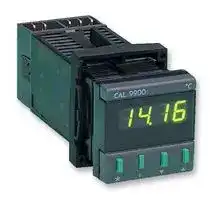
Illustrative purposes only

992.12C
Temperature Controller, Model 9900, Autotune, PID, 230 Vac, SSR, Relay Outputs
⚠️ Reference pricing provided. In case of supply shortages, we will connect you with our trusted procurement partners to ensure your project's continuity.
- Manufacturer: CAL CONTROLS
- Product type: Temperature Controllers
- Thermocouple Type: B, E, J, K, L, N, R, S, T
- Output Voltage Max: 250VAC
- Operating Temperature Max: 1800°C
- Operating Temperature Min: -200°C
| Delivery and price | |
|---|---|
| Units per pack | 1 |
| Price | 289.34 € |
| Current stock | 10+ |
| Lead time | 30 days |
Datasheet

**==> picture [540 x 706] intentionally omitted <==**

**----- Start of picture text -----**<br>
install the 9900 controller in panel see 10.2 ____ INSTALLATION AND OPERATING MANUAL |<br>Wire up connections see 10.1 tt—C(i‘COOOCtsSstststsCSCs:Ctstisi‘“C(C(‘(‘(‘(‘(‘(‘(‘(‘(‘(‘(‘i‘(‘(‘(‘(‘(<(‘i‘a‘i‘i‘i‘i‘(‘(‘(‘(‘(‘CS<br>Step | aemeananina - < s&s { |<br>UP = os a. oo temperature<br>POWER BRE S os da . Hi a Process<br>ee . J PI<br>Ra Error<br>Step [2] POMS) a. iq Aha ROCCO_ . «. S Bsee eece aeee ne Sp2<br>ZEROindicating FLASHESno  ONsensor LEFT | i6 >- The CAL 9900 microprocessor based xoh, Sea Viewne seteepoint<br>selected a. temperature controller provides precise % JX Pectease<br>ButtonsNote only adjust flashing digitsey se= advancedcontrol withAutotunea minimumalgorithm ofsettingtunesup, allthe eGRKEYCONTENTSGUIDERees =<br>(shown green) five control parameters automatically. _ _@importantcaution - please read first _<br>scan ~~ The simple setting up procedure below is |<br>Step JGIMNGHOR| GGA OG<br> 3 —— <: normally sufficient, specialised applic- 23! So ee CC<br>press 10 SELECT ations may need the comprehensive es a<br>SENSOR eg. Type K = 2 _ 9900 features covered in this manual 7 Alarms MW Error messages<br>Sensor options: ee Ke ;<br>(For full fable see 8) oe <8 SOc Ne Se Ee Re Bee ES SER ER SE Se Se Bee Bee o<br>rK 1 R 4 E 7 RID 9 Stepp 8 PMCSAn Autotunufotuned parametersrameters — Aufotune limitsinnit:<br>N 2 $§ 5 L 8 | POO PRESS § TO ACCESS . LAL Entered automatically:<br>3 T 6 B 10 PROGRAM MODE a Proportional band/Gain 0.5 ~ 2G c/range<br>Function O flashes ea integral time/Reset 0.2 + 43.5 min<br>Step 4 ee on tight Poe eG Derivative time/Rate 1,0 - 255 sec —<br>p . Ps DAC approach control 0.5 ~ 9.0 x gain<br>PRESS p TO ENTER . .<br>SENSOR INTO MEMORY Proportional cycle time O.8 - 819 sec<br>Display shows process ee Step 9 CENCE C<br>remperolure , pee calculated but for safety reasons needs<br>29. Neen& gees: ” TOpressOPTION %€ 1OSELECTION CHANGE manual acceptance see 6<br>Option O flashes aeRO temp<br>PRESS 9% TO DISPLAY tag EL a 7<br>. <rLae Step 10 SECwm 75% SP|| JfoMono \\ enterednew PID valuesand<br>BE SEE PRESS &To SELECT . Lt H oe tuning cycles output power<br>i3 AUTOTUNE ‘AT’ r aa | ferappted<br>Step Se Option 1 See f i<br> 6 HERRERA i:* i:SsaeaHee Start AT SRRio Isevere4 tre<br>ie J<br>PRESS 1OO% output<br> AND HOLDPRESS sie .Se142] Step 7] saueaeaCr?— uaseR CCS Fig.1 } AuAutotuneCOE  ATCulex Powe)<br>TO INCREASE & Pee eg | 3.9 AUTOTUNE PT (Push-to-Tune)<br>SET POINT ER (FA press 10 START Select Opt 2 at 2 step 10<br>os cs AUTOTUNE ‘AT’ ae Used to fine tune difficult applications at set<br>Output turns on and temperature~ —tises SSor© 8 conditionspoint, Useful areif the substantiallyset point changed. or thermalDuring<br>The controller is now Prop band 2.5% K isPTunacceptable,tuning some overshoottemporarilywillreduceoccur. Ifsetthis<br>_ operational with Prop time 20 sec seccntanmepenemganesnuenen point. PT tunes the parameters listed above<br>factory PID settings: Derivative 25 sec AT and Process SEES except DAC. Proportional cycie time is re~<br>integral 5 min temperature displayed calculated but needs manual acceptance<br>DAC approach alternately during<br>control 15 Autotune eccacosuesenasncers temp<br>Ce_ @IMPORTANT - Pleaseeefeqd belore using _ Poe ee Startes:PT during<br>12 NegativeifProportionalrequired4 d temperatureadjust:adjust:cycie-time:R"4Range.ranging,. 204Hires sec olefactory9068O.1°. BSEe& AUTOTUNETwoAUTOTUNETYPESANDCetypes ofTYPES AutotuneEMME. AND {CRE USESare provided=vteatsto : set point KaciVNMeeni  AEE| iningoo.Mu on/offevetesonsomce |:| PP| Seinetuningentered[new POPID values<br>set, i unsuitable change now or use. ensure optimum control of a wide range ee eyes<br>Autotune calculated value after tuning of applications l |<br>3. Forrun seebest 6results use normal set point AUTOTUNE AT ~ Normal method, tunes +(CO% output power}  time<br>4 and load conditions during warm up<br>Start Autotune AT with the load coal Fig. 2 Autotune PT<br>TO AUTCTUNE difficultAUTOTUNEapplications,PT ~ (Push-to-Tune)tunes at  —set Forpoint 3.3 OVERIDING AUTOTUNE VALUES<br>Stap 7 wos o.1 AUTOTUNE AT Affer AT/PT any Autotuned parameter may<br>START 4c be changed to an Option from the table.<br>NEAR  AUTOTUNEAMBIENT ‘AT’ . coa) tuningStart Autofunecycle occurs AT withat the75% loadset cool.point Aduring short memory.The original Autotuned value is retained in<br>oe warm up. New PID values are automatically Note Subsequent Autotune AT or PT run<br>So entered and the temperature rises to set replaces manual selections with new<br>SSS point . calculated values (except Cycle time)<br>**----- End of picture text -----**<br>


A CONTROLERFUNCTIONS = BRatotuNEHINTS “BPAYAND SELECTION roceoune = S[AUIOTUNEHINTS,] = Sto oo— Thethe. Functionsfacilitiesssa ofandthe Options9900 areTableselectedsee . &from %,{ (latched:Autofuneheart PRESSerror messageswy¥ &4 to reset)s@@ 11 (EE5-7) pressiF AT VALUE} TO ACCEPTSUITABLE Se aea mode butAT/PTif tuning tunes mostfails and applicationserror mes **sa** tisfactorily,ges AT VALUE Ermrote aE| “unetions (Fn) - The available controller repectealy occur,the application has NOW OPERATIONAL & Options (Opt) ~ The available values for unusual characteristics requiring manual EAT VALUE UNSUITABLE Sagamore each Function e.g. Function § Option O tuning see 2] OR! WEY (Fn 5/Opt O} = SPT Prop band of 2.5% <3 . . . . PRESS @& TO SELECT A NoteOptions1 Shouldcheckditficutyfhe Parameter occur inlock adjustingsee 14 $2 TuningDifficull withbothsetto pointcontrolnearand ambientAutotune. Use SUITABLEFROM TABLEOPTION TSS Note 2. Normal control is maintained with PT. if tuning fails try with Fn 5/Qpt 3, othereg. Option 4; 30 sec ee existing settings during programming wise Increase set point or tune manually ee Ms weapon. 3.8 In High Resolution (0.1%) SAATC Funct — PRESS p TO ENTER Should error message EE6 occur during ycle time va HES ININEN PROGRAM MODE eee ning.Opt O) selectthen normalAutotuneresolutionand afterwards(Fn 18/ enableTwo AT cyclethe currenttime valuesoperationalare stored,value toto be ce re-select Hi-res, (check range setting Fn 24) retained, until a new value from a subocoeoo_—_— sequent Autfotune run is considered Step P 2 _ 3.4 AUTOTUNE VALUE DISPLAY Example of two AT cycie time values offer At the end of an Autotune run the AT value a supsequen! Aujofune muy PRESS AND HOLD && is automatically entered and may be Step § scaiieeniia INDEX TO .FUNCTION disployed in Functions: ; Index to Function. 4 @g,. Function 16 ee 5 Prop band/Gain Operational AT volue- 98 sec4 (Sensor select) Soe é Derivative time/Rate ae. flashes yee ae 7 DAC approach control As accepted previously" TTT Cas 8 integral time/Reset (Step 4) Note 3 LED's ON“ oe StepPRESS 3 We CHANGE TO ee Steppress| P to enter REN nePRESS * ‘3ke TO CHANGE TO OPTIONconsuneneseanesneaye SELECTION OPTION SELECTION PROGRAM MODE Step 7 — oh. aa Latest caiculated AT value" a oe e.g. 72 sec Oe os Note Flashing bar ee Step 4 ssuuaeauenensnnes Step 2 ouncaamn step 8 ; CQ pressSELECT WorOPTIONats Py !. 15"" PressFUNCTION& 12 INDEX A PRESSneedis! to acceptactions:the latest calculatedSG REQUIRED oS eg. Function 5 Prop band 4 2ee AT value - 7.2 sec which replaces 9.8 sec ag. Option I (ype J) - = AT value = 35% vA oe aoe as the operational AT value if £3 f “£0 OR PRESS W to display current operational Step 5 Sunshine Note 3 LED's show an AT value displayed AT value. Then PRESS p to retain 9.8 secs PRESSBE CHANGE TO 6© SoPROPORTIONALee ee OR PRESS yeto select Option from Table FUNCTION SELECTION iCYCLE TIME apes sgestngsganranacingrerenetnennanneeateesgna neerenegunaneeennenee Set other Functions = CO. Autotuned cycle time aAOARMS as required pote 8G Autotune calculates the optimurs value but ¥.4 SP2 Operating mode = for safety reasons does not automatically The operating mode must be selected at implement it Function 19 before adjusting SP2 at Function 2 StepPRESS6 . Yael &.9 tf the cycle time needed is known ¥.2 Aiarm oufput operation p TO EXIT Ls c og Uf Applications known to require sharter times Ge erga Bad Spo real ED on aching the PROGRAM MODE WHEN 2 than the 2 sec factory setting, including Glarm condition (Not with SP2 in Proportional SELECTIONS COMPLETE eee SSR drive (1 sec), linear outputs (0.05 sec) mode) : Process temperature .a should select the appropriate Option in : displayed ; cor= FunctionThis setting4 usingwill not the procedure,be changed. seebut may4. 2.4 LBA - Loop. break alarm see Fig. 3 Controlinstructions commences with new be replaced with the caicuiated AT value Usphave on enor,meroP EE andalarm now entered in memory if preferred after the Autotune run relay oraly be configured to act also 4.2 MODEPROCEDUREB ~AGRE FUNCTION/OPTION DISPLAY 8.8 NormalRun Autotune procedure AT see 2. When complete _ seme.ihe cee~ eefechnicaly.nsgpense: to toutIne outputis saturatedreceve Used in Function 2 to set full scale alarms (alternating AT display stops) display the AT OCCUTS WEN SIT OUTHUE IS sarurare: and Function 24 - Range adjustment calculated cycle time and accept if O% oF 100% and the ee temperate Mode’ B enables all digits to be used for suilable. this will then replace the 2O sec fails to move a minimum prop Band in OntiStDHONSep j Valuesi SSRN ens7 factoryStep 7 setting SRGaSSG RES thebyQOLBALBACartesiiesalarmfime.SensogSP!canditionSreeoutputSENSO:state aiscannectadis unaffected PRESS. TO INDEX Index fo Function 4 sie sae vee] TO FUNCTION “db For procedure see 4 | ee eS eg.(RangeflashesFunctionadjustment) 24 a~~eSSaar-= Optionactory ©:setting 20 sec oooi, oo. 2Pf oeraatya. RRO=od aetoss of Note 2 bars = Mode 8 Komt Sulu!anGUvICES wEeRdRe!sect OF ODENopen CHCui onegy (vives supp Step 2 BGR UEENEN Step 2 a Fig. 3 Typical faults detected by LBA press % 10 DISPLAY » WDD press * 10 CHANGE ?.4 Selecting LBA - EE3 message only OPTION VALUE a TO OPTION SELECTION ), Index to Function 12 - LBA time eg, Range 400° oO Oj Option © ~ LBA OUT. displayed flashes Aaa BER 2. PRESS ¥€ to change fo option selection Step 3 Casee ood Step 3 <; —cemeusupmnaemneysree 3. (2ThePRESSx recommendedIntegral@ to selecttime inOptionuse)initial 4setting PRESS AND HOLD 3& PRESS &ATO DISPLAY 4. LBA alarm condition: EES displayed, PRESS a ¥ 50g CALCUL ATED AT VALUE _ Ea alternating with process temperature : TO INCREASE oe ag. 9.8 sec a 5 display latches, to reset PRESS Yay tagether OPTIONpats M 10 DECREASE £5,Seeee ae ae showsNote Flc **a** shinglculatedbar ~~AT Sec ToOpti c **o** nfiguren 6 In FunctionAlarrn relay19 (Relay SP2 to latches LBA Selectin VALUE os— CS value is displayed oS alarmNote condition.Use LBA withto resetSP2 ON/OFFPRESS Wea.mode) only (Fn 10/Opt ©). Reset EES/Relay before any other program changes

**==> picture [520 x 731] intentionally omitted <==**

**----- Start of picture text -----**<br>
FUNCTIONS_ | Please readANDtheseOPTIONSimportant TABLEnotes first<br>1. Factory setting: is Option O 3. Protected Functions: 5. Locating Functions: ;<br>(except Functions 2 and 22) All Functions, except User Settings (Functions Function © is the Prograrn mode entry point<br>L 2. 3) may oe locked in memory cfter<br>2. FunctionsInitial configuration:16-24 must be selected first then Ss e ttinge 14 toParameter prevent tampering.lock Pressing [a] ; [increments]<br>enteredmode - seeinto memory4 then Autotune by exitingandProgramofher 4. AT values (marked Am ): WY movesfor access directto tohigherFunctionFunctions B<br>Functions may be selected y Hold pressed to auto index through table<br>As calculated on the latest AT or PT run (Functions 13, 14, 25 are unused)<br>No. Ro Parameter . ia ger Parameter . “o er Parameter<br>OPERATING MODE..Profected OPERATIONAL PARAMETERS ... continued INITIAL CONFIGURATION ... Prolected _<br>O Operating mode | — 7 $§P1 DAC approach control — 16 Sensor Select and Range Tabie<br>fe) Normal Operation & © 1xpropband § 30 a Range Tabie<br>} start Autohnve AT - } as 6 40 Sensor<br>3 Parkart  modeAutotune = 3 20, 7 & ATvolue x Type Factory set range (SR)<br>4-100 Manual heat % eS 4 25 ¥ e<br>si ntegral time - J<br>__USERSETTINGS Unprotected BK 409 809 1200 1999<br>1 Manual Reset (OUT IN PID) . 1 OUT 9 7 min . 4 R 1600 1999 1600 1999<br>ae 2 O8min 10 13min — 5 Ss 1600 1999 1600 1999<br>1° steps (max +127°/50% prop band) 3. min VW 25min se 6 6CT 250 SOO 250 S00<br>2 $P2 Adjust. &5 45 2min3min 12)13. 3343 minmin e 87 CEL 400500 100080O 600800 HOO1470<br>1° SS 6 lOmin A = 10 8B OO = 1999 1800 1999<br>steps Factory setting 5° = 7 min 14 @ Atvalue<br>5P2 mode must be selected in a e o RTD<br>Function 19 before adjusting SP2 a _ 9 PTIOO 200 400 400 750<br>SP2 Option | Function — 9 Sensor error correction a Range minimum: 0° C/32°F<br> mode (Fn 19%)“ No. 2 range Except T/PTIOO:<br>Deviationull scale alarmalarm }-= 2 oS ae ae<0. $P21° Proportionalsteps (+127° max)cycle time ase MinimumFactory setavailableO° C/32-2009C/ °F  °F<br>Cool strategy 7 t127° a Linear process inputs Display<br>(#* Sensor range : Fn 16) =c ©1 ON/OFFtsec 910 3sec7? sec &. WO -20mv O- 100<br>3 SPI Lock a= 3.2 Ssec10sec VW12 1445sec sec =. 13°12 4O -20mvV- 20mvV O-© - 1001000<br>° Unlocked G‘ 54 6020secsec forNon Coollinearrangesstrategy | 141§ 4© -- 20mvV20mV OO- - 10002000<br>} Locked & 6 O05sec 13. 015-10 sec :<br>“oe utenti siti esi 7 . 7 30sec 14 015-20 sec ~— 17 Negative temperature ranging<br>ee 8 2sec 1S 006-15 sec q<br>| QPERATIONAL PARAMETERS .. Protected : © Pisabled ; °<br>HESSD SSSI S IS ESESSESS 1 § . Brgportional SP2 Hysteresis S 1 Enabled (range min -200°)<br>4 ~— §P1 Proportional cycie time = band/Gain in ON/OFF mode |. ;<br>S - 18 Display resolution<br>O 20sec 10 3sec - QO 25% CR 1.25% .<br>11sec HW 7 sec a 1 OS% 0.28% = O Normal (1°)<br>2 Ssec 12 14sec a 2 1% O5% Se 1 Hi-res (0.1?) +199.9°<br>3. 10sec 13 45 sec :<br>4 3 2% 1% ie 1° settings become ©.1°<br>5 30sec a oO erational 4 3% 15% : Ranged © - 200° on selection<br>6 60sec 148 aPeaue 5 5% 25% . of Hi-res, (reset with Fn 24)<br>7 ON/OFF©.05 sec ¥ Latest =a 67 21 0 %% 5%10% & 19 $P2 Operating mode<br>8 O3sec 15 @@ calculated 8 15% O75% o Select and enter Function 19 before<br>9 22sec AT value Fs g 4% 2% 2 adjusting $P2 in Function 2<br>x 10 6% 3% .<br>5 SPI Proportional SP! Hysteresis i. Wy 7% 35% . Oo OUT<br>band/Gain in ON/OFF mode 12 8% 4% 1 Deviation alarm ~ High<br>a 13 14% 7% oS 2. Deviation alarm — Low<br>O 25% CR 1.25% - 14 100% 50% . 3. Deviation band alarm<br>1 O5% 0.25% = . 4 Full scale alarm ~ High<br>2%. O5% 12 LBA... Loop break alarm - time : 5 Full scale alarm ~ Low<br>3° 2% 1% is = 6 (BA- Loop break alarm<br>4 3% 15% 2 © OUT 9 30min a 7 Cool strategy<br>§ 5% 25% S 1 ITmin 10 40 min &<br>6 10% 5% u 2 2min It SO min ~ 20 SP} Sensor break ;<br>7 20% 10% Ee 3. Amin 12. 7O min me<br>& 15% ©O.75% = 4 66min 13° 90 min 8 O Upscale<br>9 4% 2% S 5 &min Recommended ee T  Downscaie<br>10 6% 3% y 6 IOmin initial setting: a<br>HW 7% 3.5% sf 7 Brmin 14 2x Operational 21 SP2 Sensor break<br>12 8% 4% & 8 20min integraltime |<br>13° 14% 7% = : © Upscale<br>14 100% 50% — Reset Functions O - 24 to factory * 1 Downscale<br>18 x settings<br>s AT value eS = 22 °C#/°F (Note Change top fascia)<br>¥ « Q Normal .<br>6 SP! Derivative time/Rate ~: 1 Reset (Function 22 not reset) x: o1 °C°F {Factorytrot resetsetby Function 16;<br>© 25sec 9 3sec Sue dancerntaertn tian estate ancy nu nenunitean nen aL 23. Software version number<br>1 OUT 1O 7sec fo , , _<br>2 5sec It sec s — 24 Configured range (CR) adjustment<br>3. 10sec 12 20sec . Abbreviations: e<br>4 §Osec 13° 35sec & : 1° steps ;<br>5 1O0sec 14 75sec : Fn ~ Function : Mode B adjustment see 42<br>& 200 sec & < Opt -— Option : (See Range Table in Function 16)<br>7 Vsec 15 & afvalue | SR - Sensor range a<br>6 22sec ¥ Sf CR - Configured range 5<br>**----- End of picture text -----**<br>


**==> picture [566 x 727] intentionally omitted <==**

**----- Start of picture text -----**<br>
OS coc 36 $P2 Latch alarms Te OrCrOnee<br>The advanced functions are intended for ©1 NormalLatch Step1 To start monotor: SelectFri 38/Opt 1<br>OEM'stherefore andprotected process engineers.in the Function Accessfableis Only for: SP2 ON/OFF mode, Fn 19/Opt 1-5 2 Tooperation retin to normal PRESS{  p<br>Cos Ss<br>SoSES] || ftnetionsPS Syeigunauinarsecremove this sectionwie OF inesetram the | tornPRESSmiescontotogether tomode, reset Fn(in non19/0Op 3 to(Readings9 view stop monitor: readings are retained) (PM/DCM) FrsFin 38/Opt 39-42  0<br>eeAES ee ee 5 Reset<br>el catedNGNONE CESS 10 ADVANtt 37 SpareDIAGNOSTICS ReadingsMonitor and resetreadings on nextreset OnFri 38/Optde- 1<br>powering<br>ep | a Read only Functions 39-49 Mode Bs sssagns ngs unnaaeecrrearngaemin<br>© LG asploy see 42 Ut<br>PeRAM [ONO] MODE [ Ber] aaeeceaee on PERFORMANCE MONITOR (PM) OSCTo be made by qualified technicain.mrnnenm De- mit<br>Ls , power controller before proceeding using a<br>SES ENS 38 = Start monitor (Entry point from Fr 13) screwfascia drivercontaining at side ofpush bezelbuttons. removeAll functions lower<br>Step 2 Bissessesssnsmneaceos OoStartOFF protectedexcept useragainstsettingstampering.- Functions To1-3protectcan be<br>PRESS ae FPS . function settings change the plastic link<br>TO FUNCTION¥ TO GO13 DIRECTLY eMin td monitorReadings arestart orresetde-powering on subsequent from unlocked to locked position._<br>ce [ee] © LOCKED (or remove fink)<br>oe oe. 39 = Read temperature variance (0.1°)<br>go «[e «] UNLOCKED<br>step 3 “mee «47 -Read minimum temperature (°C/°F) 19 INTERNALHNIGHANGES<br>PRESS & HOLD ;HE FOR § sec EAma Q 42 Read% heat Duty (SPT Cycle % ON Monitor time)  (DCM) Thesemods operational By a qualified modifications technician before should be<br>FUNCTIONS queen installation.<br>Entry point Fn 38) Meas + AUTOTUNE TUNING DATA fig, 8 To remove the 99004 board:<br>SOO 1, First removethe output module. carefully<br>Cony Overshoot/Undershoot (°C/°F) lever the retaining clips from the slots in<br><< Max 255° /Hi-res 25.5° the module cover with a small<br>32,_ 182  acADVANCED RUNCHONEFUNCTIONS . ProtectedPoca 3 Set 45 US screwmodulecover ouput module<br>fn get Parameter ol | .<br>26 » SPINo. Heat Power limit QuarterMin 2 sec/max cycle times18OO sec (sec)(30 min) “1= ES >— | =<br>Ob nat100% maxcutout 98 6055 % 4g aeTI 3 actsT 2. Tapshown,Carefully module fo remove releasecover theboard, on 9900Atable avoid top. board. darnagingas<br>$ ise 19 see 5O Spare PRESS. to Fn O components on protruding tongue<br>4 80% 12 40% Min oe oy 99004 board ~.<br>5 75% 13 30% ‘19:3 DIAGNOSTICS Functions 38-49 SS a /<br>7 65% 4 10% To assist with machine development, = ude<br>commissioning and trouble shooting ai _<br>Not in SP1 ON/OFF mode 15.1 To convert to 3 wire RTD/PT100<br>27 §P2 Cool limit PERFORMANCE MONITOR (PM) Gaiiors thermocouple operation) 4<br>Monitors and displays minimum and Carefully Cut pad at x avoid damage to R3.<br>9 100% ewesmax 4 40% marirmum temperatures and variance Fit soldier links LK1, LK2 using 22SWG wire.<br>2 60% 6 30% Displayed temperatures are measured Ss. ce a.<br>3 50% 7 10% values, independant of set point. This Se t<br>high sensitivity monitor may be affected Polis EOP<br>Not in SP2 ON/OFF mode byileerence, (Fit snubber to minimise SS 2 oO<br>Direct/Reverse mode selection hen tere |fo Fp2‘ :a : ce “G SSeS =<br>Normal logically ON i rr————C“C RCC<br>2928 = SPi Output co) con y ae oo 18.2. Supply Voltage Conversion (Plugin links)<br>3031 SPILEDSP2 Output fe)oO 1] SUeeReTs Soa naceToSos operating voltageIMPORTANT - checkbefore your installationproceeding.|<br>SP2 LED fe) 1 Oe Wrongful conversion could damage this<br>32 Error indicator resolution bo For 115 Volt +15% operation fit two links<br>© i ee (spare link in accessories bag) in positions<br>1 HighNormal(1%) (2% range/segment) Fig. 7 Performance monitor (PM) Frns 38-4] one118 andlink in115.positionFor 230230, Volt + 15% operation fit<br>2 Low (4%) DUTY CYCLE MONITOR (DCM)<br>33. Temperature display sensitivity Monitors percentage power used in the 16 9900 FUNCTION/OPTION RECORD<br>previous propartioning cycle. Average Customer<br>© Normal several readings for a more accurate result Ref;<br>1 High Power requirements outside the range ‘del ,<br>2 Low 20% - 8O% may be difficult to confro! mc serene<br>34 Derivative polling ratio and autotune 9900 a ee———<br>O 05x derivative time sca sey gamut aatnrrerend<br>2 33 ee crea reeatnacye termaernerneerty Number | date:<br>35 Sensor span adjust seoeae<br>1% steps (415° 162 max) — eo ee<br>ee eh eSa<br>Note ‘Hidden’functions,Fnexcept15/OptFn5 22resets ALL <0Fig. 8 Somereves fimen(@D ee<br>**----- End of picture text -----**<br>


UV apcanans oe CAUMRATINGTa enable the 9900TOAcalibrationMINOR STANDARDto match «29 MO1. UNNGProportional NOTEScycle time: Fns 4/10 Cool strategy: A change in ioad causes an external meter, data logger etc. Determines the cycle rate of the output movementManas of the linked heat and cool prop (ie. ‘Remote’ reading) device temp SENSOR ERROR CORRECTION: Fn 9 Output device Recommended Prop 100%: ; 4a 5 Provides correction at one single time eemee oeaane es. Li oe **t** emperatureere— ietaitBee Ce ead 9900relays Internal econtacts secsec minumwith & snubber)derate4 8 i “Remote UFPoe ae Linear output 0.05 sec fo 3 4 6 ee ee (mA/Vdc) 1. Integral causes linked prop bands to AEST SSS QO BOGIES ESS OES ee ee move up Example Reads 2. Stabilises e.g. 30% heat 9900 _ 404° ideal Too long 3. Exothermic© Move proploadbands changedown causesminimisingintegral ErrorRemote’ 400+4° Set (-4) correction at Fn (oscillates), 4. disturbance ; Note Error polarity applies to 9900 2 Proportional band/Gain: Fn 5/11 Minimum offset achieved (4a = offset correction Smooths out asciliation occuring in 5 without cool strategy integral action) ON/OFF control 6, Consistent dead band throughout Sensor span adjust: Fn 3So Se 17.1. SETTING UP ROUTINE FOR-HEAT COOL ofadusimenttemperatures require differingfing amountamounts ioo a (Single zone procedure) HER eae— Too narrow Too wide !. epRun Autotune AT: (Set normal ai S.tssCsC (oscillates), (slow warm up and operating temp) Accept AT wee response) proportional cycle time | Fn 4/Opt 15 Oe Fee 3. Integral time/Reset: Fn 8 Sompatbie withvewtching devices used -. Automatically corrects offset errors (SP2 cool output is OFF af this stage) ess ~ cevtwmtaueisenmneey -geateneenasserenyeneeeon 2. When temperature stable at ac ar set point: 1, Choose a temperature towards the SS ee ee ® Select cool strategy Fn 19/Opt7 battom of the normal operating range i | rtTe ® Select cool prop band option and one at the top i ROSE SENS value from table nearest to Heat 2, Run at the lower temperature T1, note Too short Too long ® prop band value (view Fn 5) Fn i the error ET betwaen 9900 and ‘Remote (overshoots and = (slow warm up and Select cool cycle time option reading oscillates) response) value nearest to Heat cycle time 3. Repeat at upper temperature T2 and o ave View END ndtooe fn? note error 4. Derivative time/Rate: Fn 6 (Factoryjus set ea5°) Nd fo Fn 2 ExampleI 11 readsfe! T2 readsd responseSuppressestoovershootdisturb and speeds 3. 9900 6° 200° GO) Ssturbances Run with normal background/ ‘Remote’ 58° 9052 ccsmsegnaineacerenenigonmnnenetes csasapesneacesnceceganeewnnen: exothermic thermal conditions, more _ rr good results should be achieved and ErrorEl= +2° E2= -§° Soe Pe Se provide the basis for fine tuning ee Eitan 4 Further adjustments: eg. Water 4. Calculation of span adjustment pe ee REeSace e nae RETR cooing.in order):yrould oscillation occur try tor Fn 35. £2 - EI teeoscillates jong an4 fooslow shortwarm up and ® Double coal prop band value Fn 11 Formula: Fr 35 = tT X CR (as Fn 24) over corrects) response under and reduce integral time value Fn & corrects) - @ Haive cool cycle time Fn 10 (-5°)- (42°) x 250° @ Introduce cool overian §=Fn 2/(-)ve Example: fn 35 = SAS § DAC approach control:[Fn][ 7] 5. Non-linear cooling 200° ~ 60° (Fn 24 CR) Tunes warm up characteristics flashFor water cooling above 1OO°C where conditions Controls when derivative to steam occurs, Select non-linear _ oO 250 fon chert rangescool cyclein time Fn 10/Opt 13-15 uo” soling=-closer 16 20t point) User 6. Fineif overshoottuning (into cool) or Fr 35 = -5° Set (-5°)in Fn 35 when—inanesensoravery remoteaniennnaineanelc from heater undershoot (into heat) occurs, slowly 5, A span error entered in Fn 35 immediately fC) achanson | makeobserving the followingthe results:adjustments, changesstabilise a **t** heT2, reading,if an error allowexists timecorrect to oaeee eas—<—S—rsss @ increase cool overlap = Fn 2/(-)ve with Fn 9. Then check at Ti, If an error Too small Too large ®@ Apply SP2 cool limit, exists check readings and calculations; (overshoot) (slow stepped progressively Fn 27/Opt} tepeat if necessary warm up) 7. It needed: Sr heat limit Fn 25/Opt | a Contact CALfor more application9 21[PIDMANUALTUNING] GUIDE = For unusual applications producing error EAS SS Optional 99OO-PIM Process inter~ o (or Reset funtions: Fn 15/Opt 1) Function item face module (Data fromm CAL) = Fn 4/Opt 7 (ON/OFF Mode) Fn O Park mode (Opt 3) This ramote module provides s Normal operating set point Temporarily turns outputs off greater versatility when using the a Then allow process to stabilise) splay: At with linear inputs a Sake several readings of: Display: @ ond Process temperature mB Useful in¥commissioning. and trouble Fn 17 Negative temperatureEnables type T/RTD-PTIOOrangingto be aaa Ampiitude A speakspws shooting, e.g. Muitizone applications used below O° C/32 °F a Time period T aA Laelou’Manualif sensor bredkheateatercontrolled % occurs (Optpower)POO% (E012) 4-100may SP]be Fn 18 NotemayDisplay effect Increased resolutionPID valuesrange,to -200°C/F, |Mee. 3. (DiagnosticsSet PID values:Fns 38/39 maySoSboSet help) opt value (Not in ON/OFF mode) Note Effect on set point and other Fn 4 Prop cycle 7 sec Nearest & values set in °C/°F ag. 100.09 in. time (Ensure 20 Display: 8&8¥ XXH (XX = % output) hi-res = JOOO® in normal 2: corer1) dewey.wi Fn 3 SPI Set point lock Fn 26 SPiLimitsHeatmaximum powerheater limit power xs band/GainFn 5 Prop Ax165x1lO0O0%“config range largerNext Stops unauthorised adjustment during warm up. Useful if heaters . Fn 6 Derivative T sec Next Fn 5 Retransmission: oversize’ = time/Rate‘ Leoo shorter With 100% prop band, accuracy Fn 27 $P2 Cool power limit o Fn 8 Integral = T_smin Next +5% configuration range using Limits maximum cooling power = time/Reset i) longer linear input/output outside prop band in heat-cool S Fn 7 DAC 18 see Se Approachcontrol factory set §=20.5

**==> picture [499 x 761] intentionally omitted <==**

**----- Start of picture text -----**<br>
9 INSTALLATION: IMPORTANT SAFETY INFORMATION PLEASEREVIEW<br>Designed for use: UL 873 - only in It is the responsibility of the installation 1, CONFIGURATION<br>products where the acceptability is engineer to ensure that this All functions are front key selectable,<br>determined by Underwriters equipment’s compliance to EN61010 is it is the responsibility of the installing<br>laboratories inc. . not impaired when fitted to the final engineer to ensure that the<br>EN61010-1-Within Installation installation and to use this equipment as configuration ts safe. Remove the<br>Categories it and Ili environment and specified in this manual, failure to do so function lock link to protect critical<br>Topolution avoid degreepossible2.hazards accessible mayFollow impairwiring thediagrams protectionandprovided.regulations. 2. functionsULTIMATE fromSAFETY fomene: ALARM<br>conductive parts of final installation coo . ; ; ee ' Normal safety advice: Do not use SP2<br>should be protectively earthed in ESC NBh SSC SS ON BUTAALS GOSS as the sole alarm where personal<br>equipment.accordance with EN61010 for Class7 oes cee ee ee ee injury or damage may be coused by<br>Output oesaCe equipment failure.<br>wiring should be within a 8 Lope {Gap oo<br>shouldgroundedbe bonded cabinet. Sensorto ground sheathsor not be e ese beeeR  resswe ns—ee SSS10.2) MECHANICAL1. Prepare a 1/16 DIN panel cut out:<br>accessible. ee Se See 45 x 45mm +0.6 -0<br>live parts should not be accessible ee ee 1.77" x 1.77" +0.02 -0<br>without use of a fool. BE OPS ee cone ee 2. Remove the socket. pressing in the<br>“V0erInertia |oo 3 . lockSlide buttonsthe controllerler intoint the cut ou.<br>(VO INSTALATON =  . Fee ss 4, Fithe mounting clip see fig. pressing<br>70.7 ELECTRICAL INSTALLATIONpa Pealce ip eae coeee Eas soresit firmly Spionallagainst the Ppanei, jackin9<br>CAUTION RISK OF ELECTRICAL SE Sascoe ave STNERA ee §. Plug on the socket<br>SHOCK. , oa (peti fe oo 6. After installation remove and discard<br>1, Check controller Jabel is the Ve ate the protective front window label<br>correct supply voltage for your Se rt— ss 7, Cleaning - if required wipe with<br>2. application, See See toee darnp cloth (water only)<br>Connections are shown on the UU<br>3 . socketFor connection label  toto socketsocket use,use,250 SEepee iy) aaesee phoney sea m VI6D! ;<br>accessoryFaston receptacles provided in oo IER ae gasket (SPON pamet cxtout<br>4, kit. oS Loa ce {| boeyfam) Mounting cp oo<br>Recommended wire size for mains ee eee 9990 oS<br>300Vvoltage(18 AWG and0.04”) outputsrated 32/0.2 to 6 Amps/ 1.0mm? SPaS. Socket “—Jste4<br>5. For use at with 70°C.; 2 wirei  RID an external eeeSoeeS|mve ES — Ca.<<.ro N Al<br>linkistequired between connections = TBP RL «| | eye EL)<br>3 and 6. TP eee<br>interference suppressors are fitted ee Ka oF<br>across relay contacts to prolong relay ~ ~ . — _ cc a a) yet<br>fife. Fuses: 250VAC rated, time lag type to IEC 127. a Soe<br>APPLICATION FAULTS INPUTS Fig. 6 buttons<br>FE} ; See 8 Function 1 for Range Table 9.<br>Sensor Check sensor Self Thermocouple - 9 types<br>cE2EE3 psn7 short check-sensor clearinggearingSelf JK fron/ConstantanChromel/Alumel Bes ReUPt SPICONTROLPropPID band/GainParameters CHARACTERISTICS0.5-100%ield se lec  CRttable<br>LBALoop = Check control Latches: L Fe/Konst S PH-10% Rh/PT Prop Cycie-time 0.05-815 or ON/OFF<br>break toop Reset N_ NiCroSil/ NiSil B Pt- 30% Rh/ integral time/Reset 0.2-43m or OUT<br>E Chromet/Con Pt - 6% Rh Derivative time/Rate 1.0-255s or OUT<br>AUTOTUNE AT/PT TUNING CYCLE FAULTS DAC approach control 0.5-9.0 x PB<br>autotuneTEVIOUS  mun is;  aborted 4 Linearity:Standards: 5PTS- 95% 48/DINsensor 43710 range see 8 GE(O N /OFFERAL Hysteresis 0.25-S0ECR)<br>EES Values are retains: J/KAL/N/E E1°C, T F2°C, B £6°C>S00°C Supply Voltage: 115V oF 230V 415%<br>EE6 Outside time limit Latches: Reset R/S O-300°C £5°C, 3001600°C T2°C 50-60Hz 6VA<br>EE? UnableO/shootto exceadsrun Autotune,limit  Latches:Latches: ResetReset CJCExternalRejection: 20:1resistance: 100(0.0$° 2 maximum/ °C) typical Digital LED Display: (Link31% digit selectable)10mm high.<br>SP1 in ON/OFF mode High brightness green...<br>SOFTWARE FAULTS Resistanceane optenet3 wire OufputError indicator:LEDs: 3SP] stepGreen LED. SP2 Amber.<br>. .<br>EE8 Calibration data Replace unit DIN 43760 100 0 site 138.5 Q 0 °C Pt Keypad: 4 Elastomeric Buttons.<br>EE9 error if it persists Linear process Inputs: O-20mV/4-20mvV = ENVIRONMENTAL<br>System error Replace unit Linearity: +15% impedence 1OOkO min Burnicity: Max. CO EOM<br>press .“Fak together to reset latched Applicable to ail inputs Installation:fude: Categoriesp TO ll and tl<br>message SR« sensor range, CR=configured range Pollution: Degree ||<br>weUniram Calibration accuracy: +O.25% 8k aay Cc Satety: ere CSA 22.2) 142-87.<br>’_CALpeANTY ContfolsSampling waran! this product Common modefrequency:rejaction:Input Negligible3Hz, CJC Ssec Protection: ——_IP&4 (withION  gasket)<br>____freeMaterialsof det ectstor inthreeworkmansh(3) years romWpand [===] ss effectSeries mode up to 14Od8,rejection: 240V,60dB,5O-50H25O-60Hz EMC Emission:frye E RaepeN50081-1ules 1S Sub part J Class A<br>_GdelectpurchaseSESESEISIEEIS1. SSO ESTING===DD SORES EN EN REL ——CSC‘ésTeompeprcatureaReference conditions: Coefficient: 22°CISOppm/+2°C, °C SR EMCAmbient:immunity: 0.50°CEN50082-1,(32-130°F)RF Field +2% FS<br>Shauid the unit malfunction, return it 115/230V + 5%, after 30m settling time Mouldings: Flame Retardent Palycarbonate<br>to the factory. if defective it will be<br>5 . inrepaired thisThere unit.areornoThis replaceduser-serviceable warrantyat no{5 voidgomes iparts the OUTPUTSOUTPUT MODULE - Dual standard ee— —<br>unit shows evidence of being Main output: SP1 - < s A ee<br>tampered with or subjected to Relay standard: = SA/250Vac resistive it: =<br>excessive heat, moisture. corrosion . SPDT/Form C . FF =<br>3. of other misuse $Sd-optional: Sv/25mA norisclated =<br>Components which wear: or damage Alarm/Cool channel output: $P2 oe © Se<br>eg. ReRelays, SSR Relay-standard: =. [3A/25OVac] [resistive] ae<br>4. To comply with this warranty the a SPDT/Form C CAL Controls Lid<br>instalation andi use rust be by $Sd-optionat: SV/25mA norisolated Bury Mead Road, Hitchin, Herts, SG5 1RT, UK<br>5 Nene, aalifed personnel 9900 Controller output module -types Tel: +44 (0) 1462-436161 Fax: +44 (0) 1462-451801<br>CALfor anyControls damageInc orshalllossbetoresponsible other aquip- SPI output SP2 SV code 230V CAL Controls inc . :<br>ment howsoever caused, which may Relay Relay 9PLNC/F —-99112C/F 1580 S.Milwaukee Avenue, Libertyville. IL 60048<br>be: experienced as a result of the Relay $$a OOL2IC/F = -991.22C/F Tel: (847) 680-7080 Fax: (847) 816-6859<br>astatghon or egy this product, hot ood Ralay ac aes 992. 12C/F<br>this ontrais liability for any breach o SSd SP221IC/F 992.22C/F<br> agreement shail not exceed the Relay - QPLOIC/F — 991.O2C/F oueee Sen changes to he erent<br>purchase price paid SSd - P920IC/F 992.02C/F information. E & OF<br>Designed by BDC Technical Services, Baidock, UK AQ) 1296<br>**----- End of picture text -----**<br>
Updated at February 9, 2023
About Novapart
Novapart is a B2B electronic component broker specialising in stock shortages and cost reduction. We source hard-to-find parts and identify compliant alternatives across a catalogue of 410,000+ components from 500+ manufacturers.
Learn more →Stock Shortage Specialist
When a component is unavailable, discontinued or has an unacceptable lead time, we tap into our network of vetted European and Asian distributors to source what you need — without compromising on quality or traceability.
Request a quote →Compliant Alternatives
We identify pin-to-pin, electrically equivalent substitutes that meet the same certifications (RoHS, AEC-Q100, REACH) as your original specification — validated against datasheets, not just part numbers. Often at a lower cost.
BOM Analysis service →