
Image not available
Illustrative purposes only

99.01.9.024.99
Relay Accessory, Modules, 99 Series
⚠️ Reference pricing provided. In case of supply shortages, we will connect you with our trusted procurement partners to ensure your project's continuity.
- Manufacturer: FINDER
- Product type: Other Relay Accessories
- Accessory Type:Modules; For Use With:-; Product Range:99 Series; SVHC:No SVHC (15-Jan-2019)
- SVHC: No SVHC (04-Feb-2026)
- For Use With: -
- Product Range: 99 Series
- Accessory Type: Modules
| Delivery and price | |
|---|---|
| Units per pack | 50 |
| Price | 3.38 € |
| Current stock | 200+ |
| Lead time | 30 days |
Datasheet

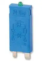
99 SERIES

99 Series - Coil indication and EMC suppression modules

||99.01<br>Sockets<br>Relays|99.01<br>Sockets<br>Relays|99.02<br>Sockets<br>Relays<br>|<br>mea<br>SP|99.02<br>Sockets<br>Relays<br>|<br>mea<br>SP|99.80<br>Sockets<br>Relays<br>Dine<br>al<br>i<br>||99.80<br>Sockets<br>Relays<br>Dine<br>al<br>i<br>||
|---|---|---|---|---|---|---|
||90.20|60.12|90.02|60.12|94.82.3|55.32|
||90.21|60.13|90.03|60.13|94.84.3|55.32, 55.34|
||94.72|55.32|92.03|62.32, 62.33|94.84.2|55.32, 55.34|
||94.73|55.33|94.02|55.32|94.92.3|55.32|
||94.74|55.32,55.34|94.03|55.33|94.94.3|55.32, 55.34|
||94.82|55.32|94.04|55.32, 55.34|95.55.3|40.51/52/61|
||95.63|40.31|94.54|55.32, 55.34||44.52, 44.62|
||96.72|56.32|95.03|40.31|95.83.3|40.31|
||96.74|56.34|95.05|40.51/52/61|95.85.3|40.51/52/61|
|||||44.52, 44.62||44.52/62|
||||95.55|40.51/52/61|95.93.3|40.31|
|||||44.52, 44.62|95.95.3|40.51/52/61|
||||96.02|56.32||44.52, 44.62|
||||96.04|56.34|97.51.3|46.61|
||||97.01/97.51 46.61|97.01/97.51 46.61|97.52.3|46.52|
||||97.02/97.52 46.52|97.02/97.52 46.52|||
|FUNCTION / OPERATING RANGE|CODE||CODE||CODE||
|Green LED + diode module (standard polarity)|||||||
|6 -   24 V DC<br>28 -   60 V DC<br>110 - 220 V DC|99.01.9.024.99<br>99.01.9.060.99<br>99.01.9.220.99||99.02.9.024.99<br>99.02.9.060.99<br>99.02.9.220.99||99.80.9.024.99<br>99.80.9.060.99<br>99.80.9.220.99||
|Green LED + diode module (non-standard polarity)|||||||
|6 -   24 V DC<br>28 -   60 V DC<br>110 - 220 V DC|99.01.9.024.79<br>99.01.9.060.79<br>99.01.9.220.79||99.02.9.024.79<br>99.02.9.060.79<br>99.02.9.220.79||99.80.9.024.79<br>99.80.9.060.79<br>99.80.9.220.79||
|Green LED + Varistor module|||||||
|6 -   24 V AC/DC<br>28 -   60 V AC/DC<br>110 - 240 V AC/DC|99.01.0.024.98<br>99.01.0.060.98<br>99.01.0.230.98||99.02.0.024.98<br>99.02.0.060.98<br>99.02.0.230.98||99.80.0.024.98<br>99.80.0.060.98<br>99.80.0.230.98||
|Green LED module|||||||
|6 -   24 V AC/DC<br>28 -   60 V AC/DC<br>110 - 240 V AC/DC|99.01.0.024.59<br>99.01.0.060.59<br>99.01.0.230.59||99.02.0.024.59<br>99.02.0.060.59<br>99.02.0.230.59||99.80.0.024.59<br>99.80.0.060.59<br>99.80.0.230.59||
|Diode module (standard polarity)|||||||
|6 - 220 V DC|99.01.3.000.00||99.02.3.000.00||99.80.3.000.00||
|Diode module (non-standard polarity)|||||||
|6 - 220 V DC|99.01.2.000.00||99.02.2.000.00||99.80.2.000.00||
|RC module|||||||
|6 -   24 V AC/DC<br>28 -   60 V AC/DC<br>110 - 240 V AC/DC|99.01.0.024.09<br>99.01.0.060.09<br>99.01.0.230.09||99.02.0.024.09<br>99.02.0.060.09<br>99.02.0.230.09||99.80.0.024.09<br>99.80.0.060.09<br>99.80.0.230.09||
|Residual current bypass module|||||||
|110 - 240 V AC|99.01.8.230.07||99.02.8.230.07||99.80.8.230.07||


1

99 SERIES

99 Series - Coil indication and EMC suppression modules

Voltage-current characteristic when switching a resistive load (fig. 1).

## Switching Relay Coils.

To counteract this potentially damaging effect, relays coils can be suppressed with a Diode, a Varistor (voltage dependent resistor) or a RC (resistor/capacitor) module – dependent on the operating voltage. (See below for descriptions of the various Modules available.)

When switching a resistive load, the current follows the phase of the voltage directly (Fig 1).

When switching relay coils the current and voltage waveforms are different due to the inductive nature of the coil (Fig 2). A brief explanation of this mechanism is as follows.

**==> picture [135 x 45] intentionally omitted <==**

**----- Start of picture text -----**<br>
U<br>I<br>U ON         OFF<br>+ R<br>– I<br>**----- End of picture text -----**<br>


Whilst the above description is based on the working of a DC coil, the reverse polarity voltage peak on de-energisation applies similarly to AC coils. However, when energising AC coils there will also be a coil inrush current of 1.3 to 1.7 times the nominal coil current – dependent on coil size. If coils are fed via a transformer (and particularly if several are energised at the same time) then this may need to taken into account when calculating the VA rating of the transformer.

t t

On energisating the coil, the build up of the magnetic field gives rise to counter electromotive forces which in turn delay the rise in coil current. On de-energisation, the sudden interruption of the coil current causes a sudden collapse of the magnetic field, which in turn induces a high voltage of reverse polarity across the coil. This reverse polarity voltage peak can reach a value typically 15 times higher than the supply voltage, and as a consequence can disturb or destroy electronic devices.

Voltage-current characteristic when switching a relay coil (fig. 2).

**==> picture [134 x 62] intentionally omitted <==**

**----- Start of picture text -----**<br>
U<br>I<br>U<br>+ R L ON        OFF<br>– I<br>**----- End of picture text -----**<br>


## Diagrams

## Functions

99.01.9.xxx.99 only 99.80.9.xxx.99 only

99.02.9.xxx.99 only

## Green LED + diode module (standard polarity)

Recovery diode modules + LED are used for DC only. The reverse voltage peaks of the coil are short circuited by the recovery diode (positive to terminal A1). The release time increases by an approximate factor of 3. If an increase of the release time is undesirable use a Varistor or RC module. The LED indicator lights up when the coil is energized.

**==> picture [86 x 57] intentionally omitted <==**

99.01.9.xxx.79 only 99.80.9.xxx.79 only

99.02.9.xxx.79 only

## Green LED + diode module (non-standard polarity)

Recovery diode modules + LED are used for DC only. The reverse voltage peaks of the coil are short circuited by the recovery diode (positive to terminal A2). The release time increases by an approximate factor of 3. If an increase of the release time is undesirable use a Varistor or RC module. The LED indicator lights up when the coil is energized.

## Green LED + Varistor module

LED modules + Varistor are used for both AC and DC coils.

The reverse voltage peaks of the relay coil are limited by the Varistor to approximately 2.5 times the nominal voltage of the supply. When using DC coils it is essential that positive is connected to terminal A1. The relay release time increases insignificantly.

## Green LED module

LED modules are used for AC and DC. The LED indicator lights up when the coil is energized. When using DC it is essential that positive is connected to terminal A1.

99.01.3.000.00 only 99.80.3.000.00 only

99.02.3.000.00 only

**==> picture [79 x 57] intentionally omitted <==**

**==> picture [62 x 55] intentionally omitted <==**

99.01.2.000.00 only 99.80.2.000.00 only

99.02.2.000.00 only

**==> picture [166 x 159] intentionally omitted <==**

## Diode module (standard polarity)

Recovery diode modules are used for DC only. The reverse voltage peaks of the coil are short circuited by the recovery diode (positive to terminal A1). The release time increases by an approximate factor of 3. If an increase of the release time is undesirable use a Varistor or RC module.

## Diode module (non-standard polarity)

Recovery diode modules are used for DC only. The reverse voltage peaks of the coil are short circuited by the recovery diode (positive to terminal A2). The release time increases by an approximate factor of 3. If an increase of the release time is undesirable use a Varistor or RC module.

## RC module

RC circuit modules are used for AC and DC coils. The reverse voltage peaks of the coil are limited by the RC module to approximately 2.5 times the nominal voltage of the supply. The relay release time increases insignificantly. Residual current bypass module Bypass modules are advisable if 110 or 230v AC relays show any tendency to fail to release. Failure to release can be caused by residual currents from AC proximity switches or inductive coupling caused through long parallel lying AC control lines.

2
Updated at June 7, 2026
About Novapart
Novapart is a B2B electronic component broker specialising in stock shortages and cost reduction. We source hard-to-find parts and identify compliant alternatives across a catalogue of 410,000+ components from 500+ manufacturers.
Learn more →Stock Shortage Specialist
When a component is unavailable, discontinued or has an unacceptable lead time, we tap into our network of vetted European and Asian distributors to source what you need — without compromising on quality or traceability.
Request a quote →Compliant Alternatives
We identify pin-to-pin, electrically equivalent substitutes that meet the same certifications (RoHS, AEC-Q100, REACH) as your original specification — validated against datasheets, not just part numbers. Often at a lower cost.
BOM Analysis service →