
Image not available
Illustrative purposes only

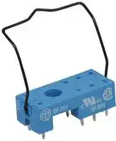
95.15.2SMA
Relay Socket, Through Hole, PC Pin, 8 Pins, 10 A, 250 V, 95 Series
⚠️ Reference pricing provided. In case of supply shortages, we will connect you with our trusted procurement partners to ensure your project's continuity.
- Manufacturer: FINDER
- Product type: Relay Sockets
- Socket Mounting:Through Hole; Socket Terminals:Through Hole; No. of Pins:8Pins; Current Rating:10A; Voltage Rating:250V; Product Range:-; SVHC:No SVHC (15-Jan-2019); Accessory Typ
- SVHC: No SVHC (04-Feb-2026)
- No. of Pins: 8Pins
- Product Range: 95 Series
- Current Rating: 10A
- Voltage Rating: 250V
- Socket Mounting: Through Hole
- Socket Terminals: PC Pin
| Delivery and price | |
|---|---|
| Units per pack | 100 |
| Price | 1.23 € |
| Current stock | 1000+ |
| Lead time | 30 days |
Datasheet

40 Series - Miniature PCB/Plug-in relays 8 - 10 - 16 A

## Features

1 & 2 Pole relay range 40.31 - 1 Pole 10 A (3.5 mm pin pitch) 40.51 - 1 Pole 10 A (5 mm pin pitch) 40.52 - 2 Pole   8 A (5 mm pin pitch)

PCB mount

- direct or via PCB socket 35 mm rail mount

- via screw and screwless sockets

- DC coils (standard or sensitive) & AC coils

- Cadmium Free contact material

- 8 mm, 6 kV (1.2/50 µs) isolation, coil-contacts

- UL Listing (certain relay/socket combinations)

**==> picture [27 x 9] intentionally omitted <==**

**----- Start of picture text -----**<br>
40.31<br>**----- End of picture text -----**<br>


- 3.5 mm contact pin pitch

- • 1 Pole 10 A • PCB or 95 series sockets

**==> picture [204 x 145] intentionally omitted <==**

**----- Start of picture text -----**<br>
40.51 40.52<br>mea Ne, aro<br>Be BED @ XS cL J |<br>1 [= =]<br>• •<br> 5 mm contact pin pitch  5 mm contact pin pitch<br>• 1 Pole 10 A • 2 Pole 8 A<br>• PCB or 95 series sockets • PCB or 95 series sockets<br>**----- End of picture text -----**<br>


- Flux proof: RT II standard, (RT III option)

- 95 series sockets

- Coil EMC suppression

- Timer accessories 86 series

**==> picture [518 x 407] intentionally omitted <==**

**----- Start of picture text -----**<br>
||||||||||||
|---|---|---|---|---|---|---|---|---|---|---|
|FOR|UL RATINGS|SEE:|Copper side view|Copper side view|Copper side view|
|“General technical information” page|V|
|Contact specification|
|Contact configuration|1 CO (SPDT)|1 CO (SPDT)|2 CO (DPDT)|
|Rated current/Maximum peak current|A|10/20|10/20|8/15|
|Rated voltage/Maximum switching voltage|V AC|250/400|250/400|250/400|
|Rated load AC1|VA|2,500|2,500|2,000|
|Rated load AC15 (230 V AC)|VA|500|500|400|
|Single phase motor rating (230 V AC)|kW|0.37|0.37|0.3|
|Breaking capacity DC1: 30/110/220 V|A|10/0.3/0.12|10/0.3/0.12|8/0.3/0.12|
|Minimum switching load|mW (V/mA)|300 (5/5)|300 (5/5)|300 (5/5)|
|Standard contact material|AgNi|AgNi|AgNi|
|Coil specification|
|Nominal voltage (UN)|V AC (50/60 Hz)|6 - 12 - 24 - 48 - 60 - 110 - 120 - 230 - 240|
|V DC|5 - 6 - 7 - 9 - 12 - 14 - 18 - 21 - 24 - 28 - 36 - 48 - 60 - 90 - 110 - 125|
|Rated power AC/DC/sens. DC|VA (50 Hz)/W/W|1.2/0.65/0.5|1.2/0.65/0.5|1.2/0.65/0.5|
|Operating range|AC|(0.8…1.1)UN|(0.8…1.1)UN|(0.8…1.1)UN|
|DC/sens. DC|(0.73…1.5)UN/(0.73…1.75)UN|(0.73…1.5)UN/(0.73…1.75)UN|(0.73…1.5)UN/(0.73…1.75)UN|
|Holding voltage|AC/DC|0.8 UN /0.4 UN|0.8 UN /0.4 UN|0.8 UN /0.4 UN|
|Must drop-out voltage|AC/DC|0.2 UN /0.1 UN|0.2 UN /0.1 UN|0.2 UN /0.1 UN|
|Technical data|
|Mechanical life AC/DC|cycles|10 · 106/20 · 106|10 · 106/20 · 106|10 · 106/20 · 106|
|Electrical life at rated load AC1|cycles|200 · 103|200 · 103|100 · 103|
|Operate/release time|ms|7/3 - (12/4 sensitive)|7/3 - (12/4 sensitive)|7/3 - (12/4 sensitive)|
|Insulation between coil and contacts (1.2/50 µs)|kV|6 (8 mm)|6 (8 mm)|6 (8 mm)|
|Dielectric strength between open contacts|V AC|1,000|1,000|1,000|
|Ambient temperature range|°C|–40…+85|–40…+85|–40…+85|
|Environmental protection|RT II**|RT II**|RT II**|
|Approvals (according to type)|€|©|@®|&|®|EB|®|a|E|A|

**----- End of picture text -----**<br>


** See general technical information “Guidelines for automatic flow solder processes” page II .

1

40 Series - Miniature PCB/Plug-in relays 8 - 10 - 16 A

## Features

**==> picture [27 x 9] intentionally omitted <==**

**----- Start of picture text -----**<br>
40.61<br>**----- End of picture text -----**<br>


**==> picture [35 x 9] intentionally omitted <==**

**----- Start of picture text -----**<br>
40.xx.6<br>**----- End of picture text -----**<br>


40.61     - 1 Pole 16 A (5 mm pin pitch) 40.xx.6  - Bistable versions of the 40.31, 40.51, 40.52 & 40.61 relays

PCB mount

- direct or via PCB socket

35 mm rail mount

- via screw and screwless sockets

- DC coils & AC coils

- Cadmium Free option available

- • 8 mm, 6 kV (1.2/50 µs) isolation, coil-contacts

- • UL Listing (certain 40.61 relay/socket combinations)

- Flux proof: RT II standard, (RT III option)

   - •

   - 5 mm contact pin pitch Bistable (single coil) versions

   - • 1 Pole 16 A of 40.31/51/52/61 • PCB or 95 series sockets • PCB or 95 series sockets

- 95 series sockets

- Coil EMC suppression

- Timer accessories 86 series

Bistable version (1 coil) types:

40.31.6... 40.51.6... 40.52.6... 40.61.6... For wiring diagrams see page 8

|_FOR ULRATINGS SEE: _|||Copper side view|||||||||
|---|---|---|---|---|---|---|---|---|---|---|---|
|_“General technical information” page_V||||||||||||
|Contact specification||||||||||||
|Contact configuration|||1 CO (SPDT)|||||||||
|Rated current/Maximum peak current||A|16/30*|||||||||
|Rated voltage/Maximum switching voltage <br>Rated load AC1||V AC<br>VA|250/400<br>4,000|||||See relays<br>40.31||||
|Rated load AC15 (230 V AC)||VA|750|||||40.51||||
|Single phase motor rating (230 V AC)||kW|0.55|||||40.52||||
|Breaking capacity DC1: 30/110/220 V|Breaking capacity DC1: 30/110/220 V|A|16/0.3/0.12|||||40.61||||
|Minimum switching load<br>mW (V/mA)|mW (V/mA)||500 (10/5)|||||||||
|Standard contact material|||AgCdO|||||||||
|Coil specification||||||||||||
|Nominal voltage (UN)<br>V AC (50/60 Hz)|||6 - 12 - 24 - 48 - 60 - 110 - 120 - 230 - 240||||5 - 6 - 12 - 24 - 48 - 110|5 - 6 - 12 - 24 - 48 - 110|||5 - 6 - 12 - 24 - 48 - 110|
|||V DC|***See table||||5 - 6 - 12 - 24 - 48 - 110|5 - 6 - 12 - 24 - 48 - 110||||
|Rated power AC/DC/sens. DC<br>VA (50 Hz)/W/W|||1.2/0.65/0.5|||||1.0/1.0/—||||
|Operating range||AC|(0.8…1.1)UN|||||(0.8…1.1)UN||||
|DC/sens. DC|||(0.73…1.5)UN/(0.8…1.5)UN||||(0.8…1.1)UN/—|||||
|Holding voltage|AC/DC||0.8 UN /0.4 UN|||||||—||
|Must drop-out voltage|AC/DC||0.2 UN /0.1 UN|||||||—||
|Technical data||||||||||||
|Mechanical life AC/DC||cycles|10 · 10<br>6/20 · 10<br>6|||||See relays||||
|Electrical life at rated load AC1||cycles|100 · 10<br>3|||||40.31||||
|Operate/release time<br>ms<br>Insulation between coil and contacts (1.2/50 µs) kV<br>Dielectric strength between open contacts V AC<br>Ambient temperature range<br>°C<br>Environmental protection|||7/3 - (12/4 sensitive)<br>6 (8 mm)<br>1,000<br>–40…+85<br>RT II**<br>~~GC®©®&~~|~~®@~~|~~®@~~||40.51<br>40.52<br>40.61<br>Min. impulse duration<br>≥20 ms<br>~~BB®wa~~||||~~©~~|
|Approvals(according to type)|||~~GC®©®&~~|~~®@~~|~~®@~~||~~BB~~|~~BB®~~|~~®~~|~~®wa~~|~~©~~|


## _FOR UL RATINGS SEE:_

_“General technical information” page_ V

* With the AgSnO2 material the maximum peak current is 120 A - 5 ms on normally open contact.

*** Nominal voltage (UN): 5 - 6 - 7 - 9 - 12 - 14 - 18 - 21 - 24 - 28 - 36 - 48 - 60 - 90 - 110  - 125 V DC

2 ** See general technical information “Guidelines for automatic flow solder processes” page II.

## 40 Series - Miniature PCB/Plug-in relays 8 - 10 - 16 A

## Features

1 Pole relay range 40.11 - 1 Pole 10 A (Flat pack) 40.11-2016 - 1 Pole 16 A (Flat pack) 40.41 - 1 Pole 10 A (Vertical) PCB mount - direct or via PCB socket (40.41 version)

**==> picture [35 x 7] intentionally omitted <==**

**----- Start of picture text -----**<br>
• DC coils<br>**----- End of picture text -----**<br>


- Cadmium Free option available

- • 8 mm, 6 kV (1.2/50 µs) isolation, coil-contacts

- • 40.41 - NO version available

**==> picture [27 x 9] intentionally omitted <==**

**----- Start of picture text -----**<br>
40.11<br>**----- End of picture text -----**<br>


**==> picture [48 x 19] intentionally omitted <==**

**----- Start of picture text -----**<br>
• 1 Pole 10 A<br>•<br> Flat pack<br>**----- End of picture text -----**<br>


- PCB mount

**==> picture [201 x 145] intentionally omitted <==**

**----- Start of picture text -----**<br>
40.11-2016 40.41<br>f are ay<br>—<br>• 1 Pole 16 A • 1 Pole 10 A<br>• Flat pack • Vertical<br>• PCB mount • PCB or 95 series socket<br>**----- End of picture text -----**<br>


**==> picture [21 x 7] intentionally omitted <==**

**----- Start of picture text -----**<br>
40.11<br>**----- End of picture text -----**<br>


40.41 _FOR UL RATINGS SEE: “General technical information” page_ V

||_FOROR UL RATINGSRATINGS SEE:: _|||Copper side view|Copper side view|Copper side view|
|---|---|---|---|---|---|---|
||_“General technical information” page_V||||||
||Contact specification||||||
||Contact configuration|||1 CO (SPDT)|1 CO (SPDT)|1 CO (SPDT)|
||Rated current/Maximumpeak current||A|10/20|16/30|10/20|
||Rated voltage/Maximum switching voltage||V AC|250/400|250/400|250/400|
||Rated load AC1||VA|2,500|4,000|2,500|
||Rated load AC15 (230 V AC)||VA|500|750|500|
||Single phase motor rating (230 V AC)||kW|0.37|0.55|0.37|
||Breaking capacity DC1: 30/110/220 V|Breaking capacity DC1: 30/110/220 V|A|10/0.3/0.12|16/0.3/0.12|10/0.3/0.12|
||Minimum switching load<br>mW (V/mA)|mW (V/mA)||300 (5/5)|500 (10/5)|300 (5/5)|
||Standard contact material|||AgCdO|AgCdO|AgCdO|
||Coil specification||||||
||Nominal voltage (UN)<br>V AC (50/60 Hz)|||—|—|—|
||||V DC|6 - 12 - 24 - 48 - 60|6 - 12 - 24 - 48|6 - 12 - 24 - 48 - 60|
||Rated power AC/DC/sens. DC<br>VA (50 Hz)/W/W|||—/—/0.5|—/—/0.5|—/—/0.5|
||Operating range||AC|—|—|—|
||DC/sens. DC|||—/(0.73…1.75)UN|—/(0.73…1.5)UN|—/(0.73…1.75)UN|
||Holding voltage|AC/DC||—/0.4 UN|—/0.4 UN|—/0.4 UN|
||Must drop-out voltage|AC/DC||—/0.1 UN|—/0.1 UN|—/0.1 UN|
||Technical data||||||
||Mechanical life AC/DC||cycles|—/20 · 10<br>6|—/20 · 10<br>6|—/20 · 10<br>6|
||Electrical life at rated load AC1||cycles|200 · 10<br>3|50 · 10<br>3|200 · 10<br>3|
||Operate/release time||ms|12/4|12/4|12/4|
|XII-2012, www.findernet.com|Insulation between coil and contacts (1.2/50 µs) kV<br>Dielectric strength between open contacts V AC<br>Ambient temperature range<br>°C<br>Environmental protection<br>Approvals(according to type)|||6 (8 mm)<br>1,000<br>–40…+70<br>RT I<br>kV|6 (8 mm)<br>1,000<br>–40…+70<br>RT I<br>CE Wis|6 (8 mm)<br>1,000<br>–40…+70<br>RT I|


3

40 Series - Miniature PCB/Plug-in relays 8 - 10 - 16 A

## Ordering information

Example: 40 series PCB relay, 2 CO (DPDT), 230 V AC coil.

A B C D 4 0 . 5 2 . 8 . 2 3 0 . 0 0 0 0 Series A: Contact material D: Special versions 0 = Standard AgNi 0 = Standard Type for 40.31/51/52, 1 = Wash tight (RT III) 1 = PCB - 3.5 mm pinning, flat AgCdO for 40.61 3 = High temperature (+ 125 °C) wash tight 3 = PCB - 3.5 mm pinning 2 = AgCdO (standard 4 = PCB - 3.5 mm pinning C: Options for 40.11/41) 5 = PCB - 5 mm pinning 0   = None 4 = AgSnO2 6 = PCB - 5 mm pinning 16 = With rated current 16 A (for 40.11) 5 = AgNi + Au (5 µm) No. of poles B: Contact circuit 1 = 1 pole 0 = CO (nPDT) for: 40.11, 10 A/16 A 3 = NO (nPST) 40.31, 10 A 40.41, 10 A 40.51, 10 A 40.61, 16 A 2 = 2 pole for: 40.52,   8 A Coil version Selecting features and options: only combinations in the same row are possible. 6 = AC/DC bistable Preferred selections for best availability are shown in bold. 7 = Sensitive DC 8 = AC (50/60 Hz) Type ~~ee~~ Coil version A ~~ee~~ B ~~ee~~ C D 9 = DC 40.11 sensitive DC **2** - 4 **0 0 0** Coil voltageSee coil specifications — | ~~L~~ 40.1140.41 ~~7ee~~ sensitive DCsensitive DC ~~y~~ 0 - **2** - 4 ~~ee~~ **2 0** 0 - 3 ~~ee~~ **0** 16 / **0** ~~esee ee~~ 40.31*/51 ~~ee~~ AC-sens. DC **0** - 2 - 5 ~~ee~~ **0** - 3 ~~ee~~ **0 0** - 1 40.31/51 ~~ee~~ DC **0** - 2 - 5 **0** - 3 **0 0** - 1 - 3 40.52 AC-sens. DC **0** - 2 - 5 **0** - 3 **0 0** - 1 ~~ee ee ee ee~~ 40.52 DC **0** - 2 - 5 **0** - 3 **0 0** - 1 - 3 ~~esee ee ee~~ 40.61* AC-sens. DC **0** - 4 **0** - 3 **0 0** - 1 ~~eeee ee~~ 40.61 DC **0** - 4 **0** - 3 **0 0** - 1 - 3 40.31/51/ bistable **0 0 0 0** ~~==55=~~ 52/61 ~~SSSee~~ * As the result of a new production line and increased production capacity, the design/specification of the sensitive DC version will be changed to align with current PCB relay versions 40.31.7.0xx.xx20 and 40.61.7.0xx.xx20. This changeover will occur during the first quarter in 2013 for  the types mentioned below. For full technical data refer to data sheet: PCB/Plug-in relays 12 - 16 A.

**==> picture [267 x 235] intentionally omitted <==**

**----- Start of picture text -----**<br>
40.31 40.31 40.61 40.61<br>Obsolete New Obsolete New<br>1 pole 10 A 1 pole 12 A 1 pole 16 A 1 pole 16 A<br>ge &<br>3.5 mm pin pitch 5 mm pin pitch<br>For socket** or pcb mount For socket or pcb mount<br>pin length 5.3 mm pin length 5.3 mm<br>Code Code<br>40.31.7.012.0000 40.61.7.012.0000<br>40.31.7.012.0001 40.61.7.012.0001<br>40.31.7.012.0300 40.61.7.012.0300<br>40.31.7.012.0301 40.61.7.012.0301<br>40.31.7.024.0000 40.61.7.024.0000<br>40.31.7.024.0001 40.61.7.024.0001<br>40.31.7.024.0300 40.61.7.024.0300<br>40.31.7.024.0301 40.61.7.024.0301<br>**----- End of picture text -----**<br>


** For 40.31 relays mounted on sockets, the maximum rated current must be limited to 10 A.

4

## 40 Series - Miniature PCB/Plug-in relays 8 - 10 - 16 A

## Technical data

|Insulation according to EN 61810-1|Insulation according to EN 61810-1|Insulation according to EN 61810-1|Insulation according to EN 61810-1|Insulation according to EN 61810-1|Insulation according to EN 61810-1|
|---|---|---|---|---|---|
|||1pole||2pole||
|Nominal voltage of supplysystem<br>V AC||230/400||230/400||
|Rated insulation voltage<br>V AC||250|400|250|400|
|Pollution degree||3|2|3|2|
|Insulation between coil and contact set||||||
|Type of insulation||Reinforced(8 mm)||Reinforced(8 mm)||
|Overvoltage category||III||III||
|Rated impulse voltage<br>kV(1.2/50µs)||6||6||
|Dielectric strength<br>V AC||4,000||4,000||
|Insulation between adjacent contacts||||||
|Type of insulation||—||Basic||
|Overvoltage category||—||II||
|Rated impulse voltage<br>kV(1.2/50µs)||—||2.5||
|Dielectric strength<br>V AC||—||2,000||
|Insulation between open contacts||||||
|Type of disconnection||Micro-disconnection||Micro-disconnection||
|Dielectric strength<br>V AC/kV (1.2/50 µs)||1,000/1.5||1,000/1.5||
|Conducted disturbance immunity||||||
|Burst(5...50)ns, 5 kHz, on A1 - A2||EN 61000-4-4||level 4(4 kV)||
|Surge (1.2/50 µs) on A1 - A2 (differential mode)||EN 61000-4-5||level 3 (2 kV)||
|Other data||||||
|Bounce time: NO/NC<br>ms||2/5||||
|Vibration resistance(5…55)Hz: NO/NC<br>g||10/4(1 changeover)||15/3(2 changeover)||
|Shock resistance|g|13||||
|Power lost to the environment|without contact current<br>W|0.6||||
||with rated current<br>W|1.2(40.11/31/41/51)||2(40.61/52/40.11-2016)||
|Recommended distance between relays|mounted on PCB<br>mm|≥5||||


5

## 40 Series - Miniature PCB/Plug-in relays 8 - 10 - 16 A

## Contact specification

F 40 - Electrical life (AC) v contact current Types 40.31/51/61

**==> picture [251 x 359] intentionally omitted <==**

**----- Start of picture text -----**<br>
Resistive load - cosϕ = 1<br>Inductive load - cosϕ = 0.4<br>limit for 40.31/51<br>F 40 - Electrical life (AC) v contact current<br>Types 40.11/41<br>Resistive load - cosϕ = 1<br>Inductive load - cosϕ = 0.4<br>limit for<br>version 10 A<br>Cycles<br>Cycles<br>**----- End of picture text -----**<br>


**==> picture [251 x 407] intentionally omitted <==**

**----- Start of picture text -----**<br>
F 40 - Electrical life (AC) v contact current<br>Type 40.52<br>Resistive load - cos ϕ  = 1<br>Inductive load - cosϕ = 0.4<br>H 40 - Maximum DC1 breaking capacity<br>40.61 current limit<br>40.11/31/41/51 current limit<br>40.52 current limit<br>40.52 - 2 contacts in series<br>single contact<br>DC voltage (V)<br>• When switching a resistive load (DC1) having voltage and current<br>values under the curve, an electrical life of ≥ 100·103 can be expected.<br>Cycles<br>DC breaking current (A)<br>**----- End of picture text -----**<br>


- In the case of DC13 loads, the connection of a diode in parallel with the load will permit a similar electrical life as for a DC1 load. Note: the release time for the load will be increased.

6

## 40 Series - Miniature PCB/Plug-in relays 8 - 10 - 16 A

## Coil specifications

## DC coil data - 0.65 W standard (types 40.31/51/52/61)

|Nominal<br>voltage<br>UN|Coil<br>code|Operating range<br>Umin<br>Umax|Operating range<br>Umin<br>Umax|Resistance <br>R|Rated coil<br>consumption<br>Iat UN|
|---|---|---|---|---|---|
|V||V|V|Ω|mA|
|5|9.005|3.65|7.5|38|130|
|6|9.006|4.4|9|55|109|
|7|9.007|5.1|10.5|75|94|
|9|9.009|6.6|13.5|125|72|
|12|9.012|8.8|18|220|55|
|14|9.014|10.2|21|300|47|
|18|9.018|13.1|27|500|36|
|21|9.021|15.3|31.5|700|30|
|24|9.024|17.5|36|900|27|
|28|9.028|20.5|42|1,200|23|
|36|9.036|26.3|54|2,000|18|
|48|9.048|35|72|3,500|14|
|60|9.060|43.8|90|5,500|11|
|90|9.090|65.7|135|12,500|7.2|
|110|9.110|80.3|165|18,000|6.2|
|125|9.125|91.2|188|23,500|5.3|


DC coil data - 0.5 W sensitive (types 40.31/51/52/61)

**==> picture [250 x 233] intentionally omitted <==**

**----- Start of picture text -----**<br>
Nominal Coil Operating range Resistance Rated coil<br>voltage code consumption<br>UN Umin* Umax** R I at UN<br>V V V Ω mA<br>5 7.005 3.7 8.8 50 100<br>6 7.006 4.4 10.5 75 80<br>7 7.007 5.1 12.2 100 70<br>9 7.009 6.6 15.8 160 56<br>12 7.012 8.8 21 288 42<br>14 7.014 10.2 24.5 400 35<br>18 7.018 13.2 31.5 650 27.7<br>21 7.021 15.4 36.9 900 23.4<br>24 7.024 17.5 42 1,150 21<br>28 7.028 20.5 49 1,600 17.5<br>36 7.036 26.3 63 2,600 13.8<br>48 7.048 35 84 4,800 10<br>60 7.060 43.8 105 7,200 8.4<br>90 7.090 65.7 157 16,200 5.6<br>110 7.110 80.3 192 23,500 4.7<br>125 7.125 91.2 219 32,000 3.9<br>**----- End of picture text -----**<br>


*Umin = 0.8 UN for 40.61              **Umax = 1.5 UN for 40.61

## DC coil data - 0.5 W sensitive (types 40.11/41)

|Nominal<br>voltage<br>UN|Coil<br>code|Operating range<br>Umin<br>Umax*|Operating range<br>Umin<br>Umax*|Resistance <br>R|Rated coil<br>consumption<br>Iat UN|
|---|---|---|---|---|---|
|V||V|V|Ω|mA|
|6|7.006|4.4|10.5|75|80|
|12|7.012|8.8|21|300|40|
|24|7.024|17.5|42|1,200|20|
|48|7.048|35|84|4,600|10.4|
|60|7.060|43.8|105|7,200|8.3|


*Umax = 1.5 UN for 40.11-2016

## AC coil data (types 40.31/51/52/61)

|Nominal<br>voltage<br>UN|Coil<br>code|Operating range<br>Umin<br>Umax|Operating range<br>Umin<br>Umax|Resistance <br>R|Rated coil<br>consumption<br>Iat UN(50Hz)|
|---|---|---|---|---|---|
|V||V|V|Ω|mA|
|6|8.006|4.8|6.6|21|168|
|12|8.012|9.6|13.2|80|90|
|24|8.024|19.2|26.4|320|45|
|48|8.048|38.4|52.8|1,350|21|
|60|8.060|48|66|2,100|16.8|
|110|8.110|88|121|6,900|9.4|
|120|8.120|96|132|9,000|8.4|
|230|8.230|184|253|28,000|5|
|240|8.240|192|264|31,500|4.1|


## AC/DC coil data - bistable (types 40.31/51/52/61)

|Nominal<br>voltage<br>UN|Coil<br>code|Operating range<br>Umin<br>Umax|Operating range<br>Umin<br>Umax|Resistance <br>R|Rated coil <br>consumption <br>Iat UN|DC: Release<br> resistance**<br>RDC|
|---|---|---|---|---|---|---|
|V||V|V|Ω|mA|Ω|
|5|6.005|4|5.5|23|215|37|
|6|6.006|4.8|6.6|33|165|62|
|12|6.012|9.6|13.2|130|83|220|
|24|6.024|19.2|26.4|520|40|910|
|48|6.048|38.4|52.8|2,100|21|3,600|
|110|6.110|88|121|11,000|10|16,500|


** RDC = Resistance in DC, RAC = 1.3 x RDC 1W

7

## 40 Series - Miniature PCB/Plug-in relays 8 - 10 - 16 A

## Coil specifications

R 40 - DC coil operating range v ambient temperature Standard coil

R 40 - DC coil operating range v ambient temperature Sensitive coil, types 40.31/51/52/61

**==> picture [511 x 140] intentionally omitted <==**

R 40 - DC coil operating range v ambient temperature Sensitive coil, types 40.11/41

R 40 - AC coil operating range v ambient temperature

**==> picture [511 x 140] intentionally omitted <==**

1 - Max. permitted coil voltage.

2 - Min. pick-up voltage with coil at ambient temperature.

**==> picture [110 x 10] intentionally omitted <==**

**----- Start of picture text -----**<br>
1 - Max. permitted coil voltage.<br>**----- End of picture text -----**<br>


2 - Min. pick-up voltage with coil at ambient temperature.

Wiring diagram for 40 series bistable coil version

## AC Operation

## DC Operation

**==> picture [511 x 92] intentionally omitted <==**

On momentary closure of the SET switch the relay is magnetised through the diode and the relay contacts transfer to the set position and remain in this position. On momentary closure of the RESET switch the relay is demagnetised through limiting resistor (RAC) and the contacts return to the reset position.

On momentary closure of the SET switch the relay is magnetised and the relay contacts transfer to the set position and remain in this position. On momentary closure of the RESET switch the relay is demagnetised through limiting resistor (RDC) and the contacts return to the reset position.

Notes: The minimum SET or RESET impulse time is 20 ms. The maximum time can be continuous. In practice, always ensure that the SET and RESET contacts cannot be operated simultaneously.

8

95 Series - Socket overview for 40 series relays

||95 Series - Socket overview for 40 series relays|95 Series - Socket overview for 40 series relays|95 Series - Socket overview for 40 series relays|95 Series - Socket overview for 40 series relays|95 Series - Socket overview for 40 series relays|95 Series - Socket overview for 40 series relays|95 Series - Socket overview for 40 series relays|
|---|---|---|---|---|---|---|---|
||95.85.3<br>See page 10<br>See page 11<br>Module Socket<br>Relay<br>Description<br>Mounting<br>Accessories<br>99.02<br>95.03<br>40.31Screw terminal (Box clamp) socket<br>Panel or 35 mm rail<br>- Coil indication and EMC<br>95.05<br>40.51<br>- Top terminals - Contacts<br>(EN 60715) mount<br>suppression modules<br>40.52<br>- Bottom terminals - Coil<br>- Jumper link<br>40.61<br>- Timer modules<br>- Plastic retaining and release<br>clip<br>Module Socket<br>Relay<br>Description<br>Mounting<br>Accessories<br>99.80 95.83.3<br>40.31Screw terminal (Box clamp) socket<br>Panel or 35 mm rail<br>- Coil indication and EMC<br>95.85.3<br>40.51<br>95.83.3 wiring:<br>(EN 60715) mount<br>suppression modules<br>40.52<br>- Top terminals - Contacts<br>- Jumper link<br>40.61<br>- Bottom terminals - Coil<br>- Plastic retaining and release<br>clip<br>95.05<br>~~a~~<br>~~a~~<br>~~a~~<br>~~aCe~~|||||||
||||||Module Socket<br>Relay<br>Description|Mounting|Accessories|
||||||99.80 95.93.3<br>40.31Screw terminal (Box clamp) socket|Panel or 35 mm rail|- Coil indication and EMC|
||||||95.95.3<br>40.51<br>- Top terminals - Contacts|(EN 60715) mount|suppression modules|
||95.95.3||||40.52<br>- Bottom terminals - Coil<br>40.61||- Jumper link<br>- Plastic retaining and release<br>clip|
||95.55<br>See page 12<br>See page 13||||Module Socket<br>Relay<br>Description<br>Mounting<br>Accessories<br>99.02<br>95.55<br>40.51Screwless terminal socket<br>Panel or 35 mm rail<br>- Coil indication and EMC<br>40.52<br>- For fast cable connections<br>(EN 60715) mount<br>suppression modules<br>40.61<br>- Top terminals - Contacts<br>- Timer modules<br>- Bottom terminals - Coil<br>- Plastic retaining and release<br>clip<br>~~ac.~~|||
||95.55.3<br>Module Socket<br>Relay<br>Description<br>Mounting<br>Accessories<br>99.80 95.55.3 40.51Screwless terminal socket<br>Panel or 35 mm rail<br>- Coil indication and EMC<br>40.52<br>For fast cable connections<br>(EN 60715) mount<br>suppression modules<br>40.61<br>- Top terminals - Contacts<br>- Plastic retaining and release<br>- Bottom terminals - Coil<br>clip<br>rt~~ne~~|||||||
||See page 14|||||||
||95.63<br>i~~e~~||||Module Socket<br>Relay<br>Description<br>99.01<br>95.63<br>40.31Screw terminal (Box clamp) socket<br>- Top terminals - Contacts<br>- Bottom terminals - Coil|Mounting<br>Panel or 35 mm rail<br>(EN 60715) mount|Accessories<br>- Coil indication and EMC<br>suppression modules<br>- Metal retaining clip|
||See page 15|||||||
|||||||||
||95.65<br>>||||Module Socket<br>Relay<br>Description<br>—<br>95.65<br>40.51<br>Screw terminal (Box clamp) socket<br>40.52<br>40.61|Mounting<br>Panel or 35 mm rail<br>(EN 60715) mount|Accessories<br>- Metal retaining clip|
||See page 15|||||||
|XII-2012, www.findernet.com|See page 16<br>95.13.2<br>~~~Ff~~|~~Ff~~|~~Ff~~|Module<br>Socket<br>Relay<br>Description<br>Mounting<br>Accessories<br>—<br>95.13.2 40.31PCB socket<br>PCB mounting<br>- Metal retaining clip<br>40.41<br>- Plastic retaining clip<br>—<br>95.15.2 40.51<br>40.52<br>40.61<br>~~Ff~~||||


9

## 95 Series - Sockets and accessories for 40 series relays

95.05

Approvals (according to type):

Certain relay/socket combinations

095.01

## 060.72

**==> picture [416 x 253] intentionally omitted <==**

**----- Start of picture text -----**<br>
|||||||
|---|---|---|---|---|---|
|Screw terminal (Box clamp) socket panel or 35 mm rail mount|95.03 (blue)|95.03.0 (black)|95.05 (blue)|95.05.0 (black)|
|For relay type|40.31|40.51, 40.52, 40.61|
|Accessories|
|Metal retaining clip|095.71|
|Plastic retaining and release clip|095.01|095.01.0|095.01|095.01.0|
|(supplied with socket - packaging code SPA)|
|8-way|jumper link|095.18|095.18.0|095.18|095.18.0|
|Identification tag|095.00.4|
|Modules (see table below)|99.02|
|Timer modules (see table below)|86.30|
|Sheet of marker tags for retaining and release clip 095.01|060.72|
|plastic, 72 tags, 6x12 mm|
|Technical data|
|Rated values|10 A - 250 V *|
|Dielectric strength|6 kV (1.2/50 µs) between coil and contacts|
|Protection category|IP 20|
|Ambient temperature|°C|–40…+70 (see diagram L95)|
|©|Screw torque|Nm|0.5|
|Wire strip length|mm|8|
|Max. wire size for 95.03 and 95.05 sockets|SCS—~SY|solid wire|stranded wire|
|mm2|fF|1x6 / 2x2.5|1x4 / 2x2.5|
|AWG|||1x10 / 2x14|1x12 / 2x14|

**----- End of picture text -----**<br>


* For currents >10 A, contact terminals must be connected in parallel (21 with 11, 24 with 14, 22 with 12). With the relay 40.51 the change-over contact will be 21-12-14.

L 95 - Total socket current vs ambient temperature (95.05)

095.18 ONS E

**==> picture [19 x 6] intentionally omitted <==**

**----- Start of picture text -----**<br>
86.30<br>**----- End of picture text -----**<br>


**==> picture [19 x 7] intentionally omitted <==**

**----- Start of picture text -----**<br>
99.02<br>**----- End of picture text -----**<br>


Approvals (according to type):

DC Modules with non-standard polarity (+A2) on request.

**==> picture [404 x 426] intentionally omitted <==**

**----- Start of picture text -----**<br>
||||||||||||
|---|---|---|---|---|---|---|---|---|---|---|
|11|COM|
|14|NO|No|
|12|NC|
|©|BB|
|3||=|ales|3)|(|=|es|3|:|
|Se|cal|5|
|cian|felt|id|||
|E=|s|le)|,|
|M|A2|i|A1|COIL|=|i|M|co|2|||
|40|60|80|158|;|36|
|(°C)|95.03|95.05|
|8-way jumper link for 95.03 and 95.05 sockets|095.18 (blue)|095.18.0 (black)|
|Rated values|g|1|10.|5|5.1|10 A - 250 V|
|pte|ee|ee|ete|2|
|15|15.8|15.8|15.8|15|.|8|15.8|15|S|
|86 series timer modules|
|(12…24)V AC/DC; Bi-function: AI, DI;|(0.05s…100h)|86.30.0.024.0000|
|(110...125)V AC; Bi-function: AI, DI;|(0.05s…100h)|86.30.8.120.0000|
|(230...240)V AC; Bi-function: AI, DI;|(0.05s…100h)|86.30.8.240.0000|
|®|
|Approvals (according to type):|CE|S|Nis|
|99.02 coil indication and EMC suppression modules for 95.03 and 95.05 sockets|
|Diode (+A1, standard polarity)|(6...220)V DC|99.02.3.000.00|
|LED|(6...24)V DC/AC|99.02.0.024.59|
|LED|(28...60)V DC/AC|99.02.0.060.59|
|LED|(110...240)V DC/AC|99.02.0.230.59|
|LED + Diode (+A1, standard polarity)|(6...24)V DC|99.02.9.024.99|
|LED + Diode  (+A1, standard polarity)|(28...60)V DC|99.02.9.060.99|
|LED + Diode  (+A1, standard polarity)|(110...220)V DC|99.02.9.220.99|
|LED + Varistor|(6...24)V DC/AC|99.02.0.024.98|
|LED + Varistor|(28...60)V DC/AC|99.02.0.060.98|
|LED + Varistor|(110...240)V DC/AC|99.02.0.230.98|
|RC circuit|(6...24)V DC/AC|99.02.0.024.09|
|RC circuit|(28...60)V DC/AC|99.02.0.060.09|
|RC circuit|(110...240)V DC/AC|99.02.0.230.09|
|Residual current by-pass|(110...240)V AC|99.02.8.230.07|

**----- End of picture text -----**<br>


10

## 95 Series - Sockets and accessories for 40 series relays

95.85.3 Approvals (according to type):

**==> picture [29 x 7] intentionally omitted <==**

**----- Start of picture text -----**<br>
095.91.3<br>**----- End of picture text -----**<br>


|Screw terminal (Box clamp) socketpanel or 35 mm rail mount<br>For relay type<br>Accessories<br>Metal retainingclip|panel or 35 mm rail mount 95.83.3 (blue)<br>95.83.30 (black) 95.85.3 (blue)<br>95.85.30 (black)<br>40.31<br>40.51, 40.52, 40.61<br>095.71<br>~~eeeee~~|panel or 35 mm rail mount 95.83.3 (blue)<br>95.83.30 (black) 95.85.3 (blue)<br>95.85.30 (black)<br>40.31<br>40.51, 40.52, 40.61<br>095.71<br>~~eeeee~~|panel or 35 mm rail mount 95.83.3 (blue)<br>95.83.30 (black) 95.85.3 (blue)<br>95.85.30 (black)<br>40.31<br>40.51, 40.52, 40.61<br>095.71<br>~~eeeee~~|panel or 35 mm rail mount 95.83.3 (blue)<br>95.83.30 (black) 95.85.3 (blue)<br>95.85.30 (black)<br>40.31<br>40.51, 40.52, 40.61<br>095.71<br>~~eeeee~~|
|---|---|---|---|---|
|Plastic retaining and release clip<br>supplied with socket -packagingcode SPA)|095.91.3<br>~~ee~~|095.91.30<br>095.91.3<br>~~eee~~|095.91.3<br>~~eee~~|095.91.30<br>~~eee~~|
|8-way jumper link|095.08<br>~~ee ~~|095.08.0<br>095.08<br> ~~eee~~|095.08<br>~~eee~~|095.08.0<br>~~eee~~|
|Identification tag|095.80.3||||
|Modules(see table below)|99.80||||
|Sheet of marker tags for retaining and release clip 095.91.3<br>plastic, 72 tags, 6x12 mm<br>Technical data<br>Rated values|Sheet of marker tags for retaining and release clip 095.91.3<br>060.72<br>10 A - 250 V *||||
|Dielectric strength|6 kV(1.2/50µs)between coil and contacts(95.83.3 only)||||
|Protection category|IP 20||||
|Ambient temperature<br>Screw torque<br>~~®@~~|°C<br>–40…+70(see diagram L95)<br>Nm<br>0.5||||
|Screw torque<br>Wire striplength<br>~~®@~~|Nm<br>0.5<br>mm<br>7<br>~~|~~||||
|Max. wire size for 95.83.3 and 95.85.3 sockets<br>AWG|solid wire<br>stranded wire<br>~~|—isdzY~~<br>~~|~~||stranded wire||
||m<br>2<br>1x6/2x2.5<br>1x4<br>~~|—isdzY~~<br>~~|sz~~<br>~~|~~||1x4/2x2.5||
||AWG<br>1x10 / 2x14<br>1x12 / 2x14<br>~~|sz~~<br>~~|~~<br>rrrrrt—(‘is—srYzY||1x12 / 2x14||


* For currents >10 A, contact terminals must be connected in parallel (21 with 11, 24 with 14, 22 with 12). 060.72 With the relay 40.51 the change-over contact will be 21-12-14.

L 95 - Total socket current vs ambient temperature (95.85.3)

**==> picture [80 x 171] intentionally omitted <==**

**----- Start of picture text -----**<br>
aeg A<br>ed as a<br>ott<br>a<br>a<br>a a<br>SLE<br>a<br>- 20 0<br>095.08<br>P E A<br>P A T E N T<br>RO N<br>EU<br>Total socket current (A)<br>UE<br>NA E POR<br>**----- End of picture text -----**<br>


**==> picture [123 x 6] intentionally omitted <==**

**----- Start of picture text -----**<br>
95.83.3 95.85.3<br>**----- End of picture text -----**<br>


8-way jumper link for 95.83.3 and 95.85.3 sockets 095.08 (blue) 095.08.0 (black) Rated values 10 A - 250 V

## 99.80 coil indication and EMC suppression modules for 95.83.3 and 95.85.3 sockets

99.80

Approvals (according to type):

*Modules in Black housing are available on request.

Green LED is standard. Red LED available on request.

||Blue*|
|---|---|
|Diode(+A1, standardpolarity)<br>(6...220)V DC|99.80.3.000.00|
|LED<br>(6...24)V DC/AC|99.80.0.024.59|
|LED<br>(28...60)V DC/AC|99.80.0.060.59|
|LED<br>(110...240)V DC/AC|99.80.0.230.59|
|LED + Diode(+A1, standardpolarity)<br>(6...24)V DC|99.80.9.024.99|
|LED + Diode(+A1, standardpolarity)<br>(28...60)V DC|99.80.9.060.99|
|LED + Diode(+A1, standardpolarity)<br>(110...220)V DC|99.80.9.220.99|
|LED + Varistor<br>(6...24)V DC/AC|99.80.0.024.98|
|LED + Varistor<br>(28...60)V DC/AC|99.80.0.060.98|
|LED + Varistor<br>(110...240)V DC/AC|99.80.0.230.98|
|RC circuit<br>(6...24)V DC/AC|99.80.0.024.09|
|RC circuit<br>(28...60)V DC/AC|99.80.0.060.09|
|RC circuit<br>(110...240)V DC/AC|99.80.0.230.09|
|Residual current by-pass<br>(110...240)V AC|99.80.8.230.07|


11

## 95 Series - Sockets and accessories for 40 series relays

95.95.3 Approvals (according to type):

**==> picture [29 x 7] intentionally omitted <==**

**----- Start of picture text -----**<br>
095.91.3<br>**----- End of picture text -----**<br>


|Screw (Box clamp) terminal socketpanel or 35 mm rail mount<br>For relay type<br>Accessories<br>Metal retainingclip|panel or 35 mm rail mount 95.93.3 (blue)<br>95.93.30 (black) 95.95.3 (blue)<br>95.95.30 (black)<br>40.31<br>40.51, 40.52, 40.61<br>095.71<br>~~ee~~|panel or 35 mm rail mount 95.93.3 (blue)<br>95.93.30 (black) 95.95.3 (blue)<br>95.95.30 (black)<br>40.31<br>40.51, 40.52, 40.61<br>095.71<br>~~ee~~|panel or 35 mm rail mount 95.93.3 (blue)<br>95.93.30 (black) 95.95.3 (blue)<br>95.95.30 (black)<br>40.31<br>40.51, 40.52, 40.61<br>095.71<br>~~ee~~|panel or 35 mm rail mount 95.93.3 (blue)<br>95.93.30 (black) 95.95.3 (blue)<br>95.95.30 (black)<br>40.31<br>40.51, 40.52, 40.61<br>095.71<br>~~ee~~|
|---|---|---|---|---|
|Plastic retainingand release clip|095.91.3<br>~~ee~~|095.91.3<br>095.91.30<br>~~ee~~<br>~~ee~~|095.91.3<br>~~ee~~<br>~~ee~~|095.91.30<br>~~ee~~|
|8-way jumper link|095.08<br>~~ee~~|095.08.0<br>~~ee~~<br>~~ee~~|095.08<br>~~ee~~<br>~~ee~~|095.08.0<br>~~ee~~|
|Identification tag|095.80.3||||
|Modules(see table below)|99.80||||
|Sheet of marker tags for retaining and release clip 095.91.3<br>plastic, 72 tags, 6x12 mm<br>Technical data<br>Rated values<br>~~o)~~|Sheet of marker tags for retaining and release clip 095.91.3<br>060.72<br>10 A - 250 V *||||
|Dielectric strength<br>~~o)~~|6 kV(1.2/50µs)between coil and contacts||||
|Protection category<br>~~o)~~|IP 20||||
|Ambient temperature<br>°C<br>Screw torque<br>Nm<br>~~o)~~|°C<br>–40…+70(see diagram L95)<br>Nm<br>0.5||||
|Screw torque<br>Nm<br>Wire striplength<br>mm<br>~~o)~~|Nm<br>0.5<br>mm<br>8<br>~~Le~~||||
|Max. wire size for 95.93.3 and 95.95.3 sockets<br>m<br>AWG|solid wire<br>~~Le~~<br>~~[|~~||stranded wire<br>~~Le~~<br>||
||m<br>2<br>1x6/2x2.5<br>~~Le~~<br>~~[|Cis~~<br>~~|~~||1x4/2x2.5<br>~~Le~~<br>~~Cis~~<br>||
||AWG<br>1x10/2x14<br>~~[|Cis~~<br>~~|—sY~~||1x12/2x14<br>~~Cis~~<br>~~—sY~~||


* For currents >10 A, contact terminals must be connected in parallel (21 with 11, 24 with 14, 22 with 12). With the relay 40.51 the change-over contact will be 21-12-14.

060.72

L 95 - Total socket current vs ambient temperature (95.95.3)

**==> picture [495 x 170] intentionally omitted <==**

**----- Start of picture text -----**<br>
io _} | i pe ft |<br>oe A DN No No p<br>ot tt tt Pt PNT ty vc oes vc = l oa<br>oft | tT tt tT IN To 2 § 2 3 2g [5 3]<br>sti | | | | | | | Tt ft ® waa ° al [ |<br>a a ena en J €<br>eg © g<br>>| | | | | | | | ft ft ft<br>con | 1( OS cor | {O S} YL<br>2 0 0 20 40 60 (°C)80 ereo gg<br>95.93.3 95.95.3<br>8-way jumper link for 95.93.3 and 95.95.3 sockets 095.08 (blue) 095.08.0 (black)<br>Rated values 10 A - 250 V<br>oO 113 .1 13 . 9<br>095.08 “ J |S SSS 1 SS SS SS SS Oo<br>P E A<br>P A T E N T<br>RO N<br>EU<br>Total socket current (A)<br>UE<br>NA E POR<br>**----- End of picture text -----**<br>


## 99.80 coil indication and EMC suppression modules for 95.93.3 and 95.95.3 sockets

99.80 Approvals (according to type):

*Modules in Black housing are available on request.

Green LED is standard. Red LED available on request.

||Blue*|
|---|---|
|Diode(+A1, standardpolarity)<br>(6...220)V DC|V DC<br>99.80.3.000.00|
|LED<br>(6...24)V DC/AC|V DC/AC<br>99.80.0.024.59|
|LED<br>(28...60)V DC/AC|V DC/AC<br>99.80.0.060.59|
|LED<br>(110...240)V DC/AC|V DC/AC<br>99.80.0.230.59|
|LED + Diode(+A1, standardpolarity)<br>(6...24)V DC|V DC<br>99.80.9.024.99|
|LED + Diode(+A1, standardpolarity)<br>(28...60)V DC|V DC<br>99.80.9.060.99|
|LED + Diode(+A1, standardpolarity)<br>(110...220)V DC|V DC<br>99.80.9.220.99|
|LED + Varistor<br>(6...24)V DC/AC|V DC/AC<br>99.80.0.024.98|
|LED + Varistor<br>(28...60)V DC/AC|V DC/AC<br>99.80.0.060.98|
|LED + Varistor<br>(110...240)V DC/AC|V DC/AC<br>99.80.0.230.98|
|RC circuit<br>(6...24)V DC/AC|V DC/AC<br>99.80.0.024.09|
|RC circuit<br>(28...60)V DC/AC|V DC/AC<br>99.80.0.060.09|
|RC circuit<br>(110...240)V DC/AC|V DC/AC<br>99.80.0.230.09|
|Residual current by-pass<br>(110...240)V AC|V AC<br>99.80.8.230.07|


12

95 Series - Sockets and accessories for 40 series relays

|Screwless terminal socketpanel or 35 mm rail mount<br>For relay type<br>Accessories<br>Metal retainingclip|95.55 (blue)<br>95.55.0 (black)<br>40.51, 40.52, 40.61<br>095.71|95.55 (blue)<br>95.55.0 (black)<br>40.51, 40.52, 40.61<br>095.71|
|---|---|---|
|Plastic retaining and release clip<br>(supplied with socket -packagingcode SPA)|095.91.3||
|Modules(see table below)|99.02||
|Timer modules(see table below)|86.30||
|Sheet of marker tags for retaining and release clip 095.91.3<br>plastic, 72 tags, 6x12 mm<br>Technical data<br>Rated values|060.72<br>10 A - 250 V *||
|Dielectric strength|6 kV(1.2/50µs)between coil and contacts||
|Protection category|IP 20||
|Ambient temperature<br>°C|–25…+70(see diagram L95)||
|Wire striplength<br>mm|8||
|Max. wire size for 95.55 socket<br>mm<br>2<br>AWG<br>~~Po~~<br>~~|~~|solid wire<br>~~Po~~|stranded wire<br>~~Po~~|
||2x(0.2...1.5)<br>~~Po~~<br>~~|~~|2x(0.2...1.5)<br>~~Po~~|
||2x(24...18)<br>~~Po~~<br>~~|~~|2x(24...18)<br>~~Po~~|


**==> picture [69 x 32] intentionally omitted <==**

**----- Start of picture text -----**<br>
95.55<br>Approvals<br>(according to type):<br>**----- End of picture text -----**<br>


* For currents >10 A, contact terminals must be connected in parallel (21 with 11, 24 with 14, 22 with 12). With the relay 40.51 the change-over contact will be 21-12-14.

**==> picture [23 x 7] intentionally omitted <==**

**----- Start of picture text -----**<br>
060.72<br>**----- End of picture text -----**<br>


**==> picture [175 x 230] intentionally omitted <==**

**----- Start of picture text -----**<br>
L 95 - Total socket current vs ambient temperature<br>20<br>ie tt | | | | | tl Tl<br>a uwf__tt| tt Ad<br>a a a<br>a<br>gt | | | | | | | | J<br>ps en<br>zit] >t | | | || tT| || ft| || ftfT<br>ot Lf | | tt ty<br>2 0 0 20 40 60<br>86 series timer modules<br>(12…24)V AC/DC;<br>(110...125)V AC;<br>%630.0.024.0009, (230...240)V AC;<br>S38<br>86.30 ava Approvals<br>Total socket current (A)<br>**----- End of picture text -----**<br>


|86 series timer modules||
|---|---|
|(12…24)V AC/DC;12…24)V AC/DC;)V AC/DC;V AC/DC;/DC;DC;;Bi-function: AI,DI; (0.05s…100h)|86.30.0.024.0000|
|(110...125)V AC;110...125)V AC;)V AC;V AC;;Bi-function: AI,DI; (0.05s…100h)|86.30.8.120.0000|
|(230...240)V AC;230...240)V AC;)V AC;V AC;;Bi-function: AI,DI; (0.05s…100h)<br>Approvals<br>(according to type):<br>®<br>CE SA;|86.30.8.240.0000|
|99.02 coil indication and EMC suppression modulesfor 95.55 socket||
|Diode(+A1,standardpolarity)<br>(6...220)V DC<br>LED<br>(6...24)V DC/AC|99.02.3.000.00<br>99.02.0.024.59|
|LED<br>(28...60)V DC/AC<br>LED<br>(110...240)V DC/AC|99.02.0.060.59<br>99.02.0.230.59|
|LED + Diode(+A1,standardpolarity)<br>(6...24)V DC|99.02.9.024.99|
|LED + Diode(+A1,standardpolarity)<br>(28...60)V DC|99.02.9.060.99|
|LED + Diode(+A1,standardpolarity)<br>(110...220)V DC|99.02.9.220.99|
|LED + Varistor<br>(6...24)V DC/AC<br>LED + Varistor<br>(28...60)V DC/AC|99.02.0.024.98<br>99.02.0.060.98|
|LED + Varistor<br>(110...240)V DC/AC|99.02.0.230.98|
|RC circuit<br>(6...24)V DC/AC|99.02.0.024.09|
|RC circuit<br>(28...60)V DC/AC<br>RC circuit<br>(110...240)V DC/AC<br>Residual current by-pass<br>(110...240)V AC|99.02.0.060.09<br>99.02.0.230.09<br>99.02.8.230.07|


Approvals (according to type):

**==> picture [71 x 33] intentionally omitted <==**

**----- Start of picture text -----**<br>
99.02<br>Approvals<br>(according to type):<br>**----- End of picture text -----**<br>


DC Modules with non-standard polarity (+A2) on request.

13

95 Series - Sockets and accessories for 40 series relays

**==> picture [467 x 202] intentionally omitted <==**

**----- Start of picture text -----**<br>
|||||
|---|---|---|---|
|Screwless terminal socket panel or 35 mm rail mount|95.55.3 (blue)|95.55.30 (black)|
|For relay type|40.51, 40.52, 40.61|
|Accessories|
|Metal retaining clip|095.71|
|Plastic retaining and release clip|095.91.3|
|(supplied with socket - packaging code SPA)|
|95.55.3|
|Modules (see table below)|99.80|
|Approvals|Sheet of marker tags for retaining and release clip 095.91.3|060.72|
|(according to type):|
|plastic, 72 tags, 6x12 mm|
|CE|CS Mi;|Technical data|
|Rated values|10 A - 250 V *|
|Dielectric strength|6 kV (1.2/50 µs) between coil and contacts|
|Protection category|IP 20|
|Ambient temperature|°C|–25…+70 (see diagram L95)|
|Wire strip length|mm|8|
|Max. wire size for 95.55.3 socket|solid wire|stranded wire|
|095.91.3|mm2|2x(0.2...1.5)|2x(0.2...1.5)|
|AWG|2x(24...18)|2x(24...18)|

**----- End of picture text -----**<br>


* For currents >10 A, contact terminals must be connected in parallel (21 with 11, 24 with 14, 22 with 12). With the relay 40.51 the change-over contact will be 21-12-14.

**==> picture [420 x 400] intentionally omitted <==**

**----- Start of picture text -----**<br>
||||||||||
|---|---|---|---|---|---|---|---|---|
|060.72|
|L 95 - Total socket current vs ambient temperature|21|COM|11|
|a000|
|20|No|24|NO|14|0|
|ea|a0|
|Ne|
|agwi|NEI|22|NC|12|
|Se|i|e|a|y|
|Ø 3.2|
|ett|FT ET|IN|oo|
|a|a|w|a|a|i|
|aa|A|Iee|ne|eald|1|§x|
|po|a|°|
|ot|Lt|||||||ft|tf|fy|ft|
|A2|COIL|A1|
|2|0|0|20|40|60|80|col|E09|
|(°C)|ales)|
|—|
|99.80 coil indication and EMC suppression modules for 95.55.3 socket|
|Blue*|
|Diode (+A1, standard polarity)|(6...220)V DC|99.80.3.000.00|
|LED|(6...24)V DC/AC|99.80.0.024.59|
|99.80|LED|(28...60)V DC/AC|99.80.0.060.59|
|LED|(110...240)V DC/AC|99.80.0.230.59|
|Approvals|
|(according to type):|LED + Diode  (+A1, standard polarity)|(6...24)V DC|99.80.9.024.99|
|LED + Diode  (+A1, standard polarity)|(28...60)V DC|99.80.9.060.99|
|LED + Diode  (+A1, standard polarity)|(110...220)V DC|99.80.9.220.99|
|LED + Varistor|(6...24)V DC/AC|99.80.0.024.98|
|*Modules in Black|LED + Varistor|(28...60)V DC/AC|99.80.0.060.98|
|housing are|LED + Varistor|(110...240)V DC/AC|99.80.0.230.98|
|available on request.|
|RC circuit|(6...24)V DC/AC|99.80.0.024.09|
|Green LED is standard.|RC circuit|(28...60)V DC/AC|99.80.0.060.09|
|Red LED available|RC circuit|(110...240)V DC/AC|99.80.0.230.09|
|on request.|Residual current by-pass|(110...240)V AC|99.80.8.230.07|
|73.7|
|24.6|4|4|
|15.8|22.6|
|32.5|

**----- End of picture text -----**<br>


14

## 95 Series - Sockets and accessories for 40 series relays

95.63 Approvals (according to type):

95.65

|Screw terminal (Box clamp) socketpanel or 35 mm rail mount<br>For relay type<br>Accessories<br>Metal retainingclip|panel or 35 mm rail mount 95.63 (blue)<br>95.65 (blue)<br>40.31<br>40.51, 40.52, 40.61<br>095.71|panel or 35 mm rail mount 95.63 (blue)<br>95.65 (blue)<br>40.31<br>40.51, 40.52, 40.61<br>095.71|
|---|---|---|
|8-way jumper link|095.08|095.08|
|Modules (see table below)|99.01|—|
|Technical data<br>Rated values|10 A - 250 V *<br>~~SS~~||
|Dielectric strength(between coil and contacts)|6 kV(1.2/50µs)<br>~~SS~~|2 kV AC<br>~~SS~~|
|Protection category|IP 20<br>~~SS~~||
|Ambient temperature<br>°C<br>Screw torque<br>Nm<br>~~©~~|°C<br>–40…+70(see diagram L95)<br>Nm<br>0.5||
|Screw torque<br>Nm<br>Wire striplength<br>mm<br>~~©~~|Nm<br>0.5<br>mm<br>7||
|Max. wire size for 95.63 and 95.65 sockets<br>AWG|solid wire|stranded wire|
||m<br>2<br>1x6/2x2.5|1x4/2x2.5|
||AWG<br>1x10/2x14|1x12/2x14|


Approvals * For currents >10 A, contact terminals must be connected in parallel (21 with 11, 24 with 14, 22 with 12). (according to type): With the relay 40.51 the change-over contact will be 21-12-14.

L 95 - Total socket current vs ambient temperature

**==> picture [78 x 171] intentionally omitted <==**

**----- Start of picture text -----**<br>
a<br>oa A<br>P<br>aa<br>a a<br>a A<br>2 0 0<br>095.08<br>P E A<br>P A T E N T<br>RO N<br>EU<br>Total socket current (A)<br>UE<br>NA E POR<br>**----- End of picture text -----**<br>


95.63 95.65

8-way jumper link for 95.63 and 95.65 sockets 095.08 (blue) Rated values 10 A - 250 V

## 99.01 coil indication and EMC suppression modules for type 95.63 socket

Blue*

99.01 Approvals (according to type):

* Modules in Black housing are available on request. Green LED is standard. Red LED available on request.

||Blue*|
|---|---|
|Diode(+A1, standardpolarity)<br>(6...220)V DC|99.01.3.000.00|
|Diode(+A2, non-standardpolarity)<br>(6...220)V DC|99.01.2.000.00|
|LED<br>(6...24)V DC/AC|99.01.0.024.59|
|LED<br>(28...60)V DC/AC|99.01.0.060.59|
|LED<br>(110...240)V DC/AC|99.01.0.230.59|
|LED + Diode(+A1, standardpolarity)<br>(6...24)V DC|99.01.9.024.99|
|LED + Diode(+A1, standardpolarity)<br>(28...60)V DC|99.01.9.060.99|
|LED + Diode(+A1, standardpolarity)<br>(110...220)V DC|99.01.9.220.99|
|LED + Diode(+A2, non-standardpolarity)<br>(6...24)V DC|99.01.9.024.79|
|LED + Diode(+A2, non-standardpolarity)<br>(28...60)V DC|99.01.9.060.79|
|LED + Diode(+A2, non-standardpolarity)<br>(110...220)V DC|99.01.9.220.79|
|LED + Varistor<br>(6...24)V DC/AC|99.01.0.024.98|
|LED + Varistor<br>(28...60)V DC/AC|99.01.0.060.98|
|LED + Varistor<br>(110...240)V DC/AC|99.01.0.230.98|
|RC circuit<br>(6...24)V DC/AC|99.01.0.024.09|
|RC circuit<br>(28...60)V DC/AC|99.01.0.060.09|
|RC circuit<br>(110...240)V DC/AC|99.01.0.230.09|
|Residual current by-pass<br>(110...240)V AC|99.01.8.230.07|


15

95 Series - Sockets and accessories for 40 series relays

**==> picture [25 x 6] intentionally omitted <==**

**----- Start of picture text -----**<br>
95.13.2<br>**----- End of picture text -----**<br>


95.15.2 Approvals (according to type):

|PCB socket<br>For relay type<br>Accessories<br>Metal retainingclip (supplied with socket -packagingcode SMA)|95.13.2 (blue)<br>95.13.20 (black) 95.15.2 (blue)<br>95.15.20 (black)<br>40.31, 40.41<br>40.51, 40.52, 40.61<br>095.51<br>———|
|---|---|
|Plastic retaining clip<br>Technical data<br>Rated values|095.52<br>10 A - 250 V *|
|Dielectric strength|6 kV(1.2/50µs)between coil and contacts|
|Protection category|IP 20|
|Ambient temperature<br>°C|–40…+70|


* For currents >10 A, contact terminals must be connected in parallel (21 with 11, 24 with 14, 22 with 12). With the relay 40.51 the change-over contact will be 21-12-14.

**==> picture [349 x 165] intentionally omitted <==**

**----- Start of picture text -----**<br>
40.31 40.51<br>13 13<br>7.5 12 14 22 24 7.5<br>1 o ' oOt1 A1 12 11 14 11 21 aloq 1 ie' %a : g<br>A2 22 21 24<br>A1 A2<br>o<br>40.52<br>95.13.2 95.15.2<br>Copper side view Copper side view<br>At 12 1114 wl<br>A2 22 21 24 arto<br>40.61<br>3.5<br>30 20 3.5<br>1.5<br>**----- End of picture text -----**<br>


## Packaging codes

How to code and identify retaining clip and packaging options for sockets.

Example:

**==> picture [168 x 13] intentionally omitted <==**

**----- Start of picture text -----**<br>
9 5 . 0 5 S P A<br>**----- End of picture text -----**<br>


**==> picture [153 x 24] intentionally omitted <==**

**----- Start of picture text -----**<br>
9 5 . 0 5<br>a<br>**----- End of picture text -----**<br>


A Standard packaging SM Metal retaining clip SP Plastic retaining clip Without retaining clip

16
Updated at June 9, 2026
About Novapart
Novapart is a B2B electronic component broker specialising in stock shortages and cost reduction. We source hard-to-find parts and identify compliant alternatives across a catalogue of 410,000+ components from 500+ manufacturers.
Learn more →Stock Shortage Specialist
When a component is unavailable, discontinued or has an unacceptable lead time, we tap into our network of vetted European and Asian distributors to source what you need — without compromising on quality or traceability.
Request a quote →Compliant Alternatives
We identify pin-to-pin, electrically equivalent substitutes that meet the same certifications (RoHS, AEC-Q100, REACH) as your original specification — validated against datasheets, not just part numbers. Often at a lower cost.
BOM Analysis service →