
Image not available
Illustrative purposes only

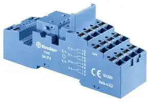
94P4SMA
Relay Socket, DIN Rail, Panel, Quick Connect, 14 Pins, 10 A, 250 V, 94 Series
⚠️ Reference pricing provided. In case of supply shortages, we will connect you with our trusted procurement partners to ensure your project's continuity.
- Manufacturer: FINDER
- Product type: Relay Sockets
- Socket Mounting:DIN Rail, Panel; Socket Terminals:Quick Connect; No. of Pins:14Pins; Current Rating:10A; Voltage Rating:250V; Product Range:94 Series; SVHC:No SVHC (15-Jan-2019)
- SVHC: No SVHC (04-Feb-2026)
- No. of Pins: 14Pins
- Product Range: 94 Series
- Current Rating: 10A
- Voltage Rating: 250V
- Socket Mounting: DIN Rail, Panel
- Socket Terminals: Quick Connect
| Delivery and price | |
|---|---|
| Units per pack | 50 |
| Price | 9.26 € |
| Current stock | 10+ |
| Lead time | 30 days |
Datasheet

**55 SERIES**

**A**

## **General purpose relays For printed circuit mounting**

**Type 55.12**

**==> picture [161 x 221] intentionally omitted <==**

**----- Start of picture text -----**<br>
 - 2 CO 10 A<br>Type 55.13<br> - 3 CO 10 A<br>Type 55.14<br> - 4 CO 7 A<br>• AC & DC coils<br>• Cadmium Free contacts<br>• Contact material options<br>• RT III (wash tight) option available<br>27.7 20.7 20.7 20.7<br>1<br>co)8<br>_s<br>es rn2 i ¥? L12 1?<br>55.12 55.13 55.14<br>**----- End of picture text -----**<br>


**==> picture [270 x 139] intentionally omitted <==**

**----- Start of picture text -----**<br>
55.12 55.13<br>| +e = *) ve hy | )<br>wsNy | ENS |<br>Ps | SNES, | ba BAO<br>• 2 CO 10 A • 3 CO 10 A • 4 CO 7 A<br>• PCB mount • PCB mount • PCB mount<br>**----- End of picture text -----**<br>


**==> picture [26 x 7] intentionally omitted <==**

**----- Start of picture text -----**<br>
55.14<br>**----- End of picture text -----**<br>


_For UL ratings see:_

||_For UL ratingsor UL ratings UL ratingsratingssee::_|_For UL ratingsor UL ratings UL ratingsratingssee::_|||||||||||
|---|---|---|---|---|---|---|---|---|---|---|---|---|
||_For UL ratingsor UL ratings UL ratingsratings see::_<br>_“General technical information” page_V||Copper side view|||Copper side view|Copper side view||Copper side view|||Copper side view|
||**Contact specification**<br>Contact configuration||2 CO (DPDT)|||3 CO (3PDT)|3 CO (3PDT)|||||4 CO (4PDT)|
||Rated current/Maximum peak current<br>A||10/20|||10/20||||||7/15|
||Rated voltage/<br>Maximum switchingvoltage|V AC|250/400|||250/400||||||250/250|
||Rated load AC1|VA|2500|||2500||||||1750|
||Rated load AC15 (230 V AC)|VA|500|||500||||||350|
||Single phase motor rating (230 V AC)<br>kW||0.37|||0.37||||||0.125|
||Breaking capacity DC1: 30/110/220 V<br>A||10/0.25/0.12|||10/0.25/0.12||||||7/0.25/0.12|
||Minimum switching load|mW (V/mA)|300 (5/5)|||300 (5/5)||||||300 (5/5)|
||Standard contact material<br>**Coil specification**||AgNi|||AgNi||||||AgNi|
||Nominal voltage (UN)|V AC (50/60 Hz)|||6 - 12 - 24 - 48 - 60 - 110 - 120 - 230 - 240|6 - 12 - 24 - 48 - 60 - 110 - 120 - 230 - 240|||6 - 12 - 24 - 48 - 60 - 110 - 120 - 230 - 240||||
|||V DC||||6 - 12 - 24 - 48 - 60 - 110 -125 - 220|||||||
||Rated power AC/DC|VA (50 Hz)/W|1.5/1|||1.5/1||||||1.5/1|
||Operating range|AC|(0.8…1.1)UN|||(0.8…1.1)UN||||||(0.8…1.1)UN|
|||DC|(0.8…1.1)UN|||(0.8…1.1)UN||||||(0.8…1.1)UN|
||Holding voltage|AC/DC|0.8 UN/ 0.5 UN|||0.8 UN/ 0.5 UN||||||0.8 UN/ 0.5 UN|
||Must drop-out voltage<br>**Technical data**|AC/DC|0.2 UN/ 0.1 UN|||0.2 UN/ 0.1 UN||||||0.2 UN/ 0.1 UN|
||Mechanical life AC/DC|cycles|20 · 106/ 50 · 106|||20 · 106/ 50 · 10|||/ 50 · 106|||20 · 106/ 50 · 106|
||Electrical life at rated load AC1|cycles|200 · 103|||200 · 103||||||150 · 103|
||Operate/release time|ms|10/5|||10/5||||||11/3|
||Insulation between coil||||||||||||
||and contacts(1.2/50μs)|kV|4||||4|||||4|
|X-2016, www.findernet.com|Dielectric strength<br>between open contacts<br>Ambient temperature range<br>Environmental protection<br>**Approvals**(according to type)|V AC<br>°C|1000<br>–40…+85<br>RT I<br>**es**|©<br>@©|©|1000<br>–40…+85<br>RT I<br> HH & @<br>B||||RINA||1000<br>–40…+85<br>RT I<br>tu**s**<br> Mi<br>&|


**1**

**55 SERIES**

**A**

## **General purpose relays For socket mounting**

## **55.32**

## **55.33**

## **55.34**

## **Type 55.32**

- 2 CO 10 A

## **Type 55.33**

- 3 CO 10 A

## **Type 55.34**

- 4 CO 7 A

- AC & DC coils

- Lockable test button and mechanical flag indicator as standard on 2 & 4 pole types

- Integral LED and coil suppression options

- 94 series sockets for PCB or 35 mm rail mounting (EN 60715) with Screw, Screwless or Push-in terminals

• 2 CO 10 A

- Plug-in 94 series sockets

- 3 CO 10 A

- Plug-in 94 series sockets

   - 4 CO 7 A

   - Plug-in 94 series sockets

- Coil Indication and EMC suppression modules 99 series and Timer module 86.30 options

- Optional alternative mounting adaptors

- UL Listing (certain relay/socket combinations)

- Cadmium Free contacts

- Contact material options

- European Patent 27.7

© 2 55.32 __? 55.33 2 55.34

_For UL ratings see:_

_“General technical information” page_ V

|**Contact specification**<br>Contact configuration||2 CO (DPDT)||3 CO (3PDT)|3 CO (3PDT)|3 CO (3PDT)|3 CO (3PDT)|4 CO (4PDT)|
|---|---|---|---|---|---|---|---|---|
|Rated current/Maximum peak current<br>A||10/20||10/20||||7/15|
|Rated voltage/<br>Maximum switchingvoltage|V AC|250/400||250/400||||250/250|
|Rated load AC1|VA|2500||2500||||1750|
|Rated load AC15 (230 V AC)|VA|500||500||||350|
|Single phase motor rating (230 V AC)<br>kW||0.37||0.37||||0.125|
|Breaking capacity DC1: 30/110/220 V<br>A||10/0.25/0.12||10/0.25/0.12||||7/0.25/0.12|
|Minimum switching load|mW (V/mA)|300 (5/5)||300 (5/5)||||300 (5/5)|
|Standard contact material<br>**Coil specification**||AgNi||AgNi||||AgNi|
|Nominal voltage (UN)|V AC (50/60 Hz)||6 - 12 - 24 - 48 - 60 - 110 - 120 - 230 - 240|6 - 12 - 24 - 48 - 60 - 110 - 120 - 230 - 240|||6 - 12 - 24 - 48 - 60 - 110 - 120 - 230 - 240||
||V DC|||6 - 12 - 24 - 48 - 60 - 110 -125 - 220|||||
|Rated power AC/DC|VA (50 Hz)/W|1.5/1||1.5/1||||1.5/1|
|Operating range|AC|(0.8…1.1)UN||(0.8…1.1)UN||||(0.8…1.1)UN|
||DC|(0.8…1.1)UN||(0.8…1.1)UN||||(0.8…1.1)UN|
|Holding voltage|AC/DC|0.8 UN/ 0.5 UN||0.8 UN/ 0.5 UN||||0.8 UN/ 0.5 UN|
|Must drop-out voltage<br>**Technical data**|AC/DC|0.2 UN/ 0.1 UN||0.2 UN/ 0.1 UN||||0.2 UN/ 0.1 UN|
|Mechanical life AC/DC|cycles|20 · 106/ 50 · 106||20 · 106/ 50 · 10|||/ 50 · 106|20 · 106/ 50 · 106|
|Electrical life at rated load AC1|cycles|200 · 103||200 · 103||||150 · 103|
|Operate/release time|ms|10/5||10/5||||11/3|
|Insulation between coil|||||||||
|and contacts(1.2/50μs)|kV|4|||4|||4|
|Dielectric strength<br>between open contacts<br>Ambient temperature range<br>Environmental protection|V AC<br>°C|1000<br>–40…+85<br>RT I<br>~~es@©~~|~~EH~~|1000<br>–40…+85<br>RT I<br>~~EH~~<br>~~S&S®BRN~~||||1000<br>–40…+85<br>RT I<br>~~®~~<br>~~Ws&~~|
|**Approvals**(according to type)||~~es@©~~|~~EH~~|~~EH~~<br>~~S&S®~~|~~®~~|~~BRN~~|~~BRN~~|~~®~~<br>~~Ws&~~|


**2**

**55 SERIES**

**A**

## **Ordering information**

Example:  55 series plug-in relay, 4 CO, 12 V DC coil, lockable test button and mechanical indicator.

**A B C D 5 5 . 3 4 . 9 . 0 1 2 . 0 0 4 0 Series A: Contact material D: Special versions** 0 =  Standard AgNi 0 **Type** 5 =  AgNi + Au 1 1 =  PCB 3 =  Plug-in **B: Contact circuit** 0 =  CO (nPDT) **C: Options No. of poles** 0 2 =  2 pole, 10 A 1 3 =  3 pole, 10 A 2 4 =  4 pole, 7 A 3 4 **Coil version** 8 =  AC (50/60 Hz) 5 9 =  DC **Coil voltage** See coil specifications

## **D: Special versions**

   - 0 = Standard 1 =  Wash tight (RT III) for 55.12, 55.13 and 55.14 only

- 0 =  CO (nPDT) **C: Options** 0 =  None 1 =  Lockable test button 2 =  Mechanical indicator 3 =  LED (AC) 4 =  Lockable test button + mechanical indicator

   - 5 =  Lockable test button + LED (AC) 54 =  Lockable test button + LED (AC) + mechanical indicator

   - 6* =  Double LED (DC non-polarized) 7* =  Lockable test button + double LED (DC non-polarized)

   - 74* =  Lockable test button + double LED (DC non-polarized) + mechanical indicator

|~~a~~|~~ee~~|||||
|---|---|---|---|---|---|
|**Type**<br>~~a~~|**Coil version**<br>~~ee~~<br>~~es~~|**A**|**B**<br>**C**||**D**|
|55.32/34<br>~~a~~|AC - DC<br>~~ee~~<br>~~es~~<br>~~es~~|0 - 5<br>~~ee~~|0<br>0<br>~~ee~~||0|
||AC<br>~~es~~<br>~~es~~<br>~~ee~~|**0**- 5<br>~~ee~~<br>~~es~~|**0**<br>2 - 3 -<br>~~ee~~<br>~~es~~|2 - 3 -**4**- 5|**0**|
||AC<br>~~es~~<br>~~ee~~<br>~~es~~|0 - 5<br>~~ee~~<br>~~es~~<br>~~ee~~|0<br>54<br>~~ee~~<br>~~es~~<br>~~ee~~||/|
||DC<br>~~ee ~~<br>~~es~~<br>~~es~~|**0**- 5<br> ~~es~~<br>~~ee~~<br>~~ee~~|**0**<br>2 -**4**- 6 - 7 - 8 - 9<br>~~es~~<br>~~ee~~<br>~~ee~~|- 6 - 7 - 8 - 9|**0**|
||DC<br>~~es ~~<br>~~es~~<br>~~es~~|0 - 5<br> ~~ee~~<br>~~ee~~<br>~~ee~~|0<br>74 - 94<br>~~ee~~<br>~~ee~~<br>~~ee~~|74 - 94|/|
|55.33|AC - DC<br>~~es ~~<br>~~es~~<br>~~es~~|**0**- 5<br> ~~ee~~<br>~~ee~~<br>~~ee~~|**0**<br>**0**<br>~~ee~~<br>~~ee~~<br>~~ee~~||**0**|
||AC<br>~~es ~~<br>~~es~~<br>~~ee~~|0 - 5<br> ~~ee~~<br>~~ee~~<br>~~es~~|0<br>1 - 3 - 5<br>~~ee~~<br>~~ee~~<br>~~es~~|1 - 3 - 5|0|
||DC<br>~~es ~~<br>~~ee~~|0 - 5<br> ~~ee~~<br>~~es~~|0<br>1 - 6 - 7 - 8 - 9<br>~~ee~~<br>~~es~~|1 - 6 - 7 - 8 - 9|0|
|55.12/13/14<br>~~ss~~|AC - DC<br>~~ee~~<br>~~ss~~|**0**- 5<br>~~es~~<br>~~ss~~|**0**<br>**0**<br>~~es~~<br>~~ss~~|~~ss~~|**0**- 1<br>~~ss~~|


- 8* =  LED + diode (DC, polarity positive to pin A1/13)

- 9* =  Lockable test button + LED + diode (DC, polarity positive to pin A1/13)

- 94* =  Lockable test button + LED + diode (DC, polarity positive to pin A1/13) + mechanical indicator

- Options not available for 220 V DC versions.

## **Descriptions: options and special versions**

**C: Option 3, 5, 54 C: Option 6, 7, 74** LED (AC) Double LED (DC non-polarized)

**==> picture [6 x 7] intentionally omitted <==**

**----- Start of picture text -----**<br>
3<br>**----- End of picture text -----**<br>


**==> picture [95 x 77] intentionally omitted <==**

**----- Start of picture text -----**<br>
1<br>2<br>**----- End of picture text -----**<br>


**C: Option 8, 9, 94** LED + diode (DC, polarity positive to pin A1/13)

**Lockable test button and mechanical flag indicator (0010, 0040, 0050, 0054, 0070, 0074, 0090, 0094)** E

The dual-purpose Finder test button can be used in two ways:

Case 1) The plastic pip (located directly above the test button) remains intact. In this case, when the test button is pushed, the contacts operate. When the test button is released the contacts return to their former state.

Case 2) The plastic pip is broken-off (using an appropriate cutting tool). In this case, (in addition to the above function), when the test button is pushed and rotated, the contacts are latched in the operating state, and remain so until the test button is rotated back to its former position. In both cases ensure that the test button actuation is swift and decisive.

**3**

**55 SERIES**

## **Technical data**

**A**

|**Insulation according to EN 61810-1**|**Insulation according to EN 61810-1**|**2 pole - 3 pole**|**2 pole - 3 pole**|**4 pole**|**4 pole**|
|---|---|---|---|---|---|
|Nominal voltage of supplysystem<br>V AC||230/400||230||
|Rated insulation voltage<br>V AC||400||250||
|Pollution degree||2||2||
|**Insulation between coil and contact set**||||||
|Type of Insulation||Basic||Basic||
|Overvoltage category||III||III||
|Rated impulse voltage<br>kV(1.2/50μs)||4||4||
|Dielectric strength<br>V AC||2000||2000||
|**Insulation between adjacent contacts**||||||
|Type of insulation||Basic||Basic||
|Overvoltage category||III||II||
|Rated impulse voltage<br>kV(1.2/50μs)||4||2.5||
|Dielectric strength<br>V AC||2000||2000||
|**Insulation between open contacts**||||||
|Type of disconnection||Micro-disconnection||Micro-disconnection||
|Dielectric strength<br>V AC/kV (1.2/50 μs)||1000/1.5||1000/1.5||
|**Conducted disturbance immunity**||||||
|Burst(5…50)ns,5 kHz,on A1 - A2||EN 61000-4-4||level 4(4 kV)||
|Surge (1.2/50 μs) on A1 - A2 (differential mode)||EN 61000-4-5||level 4 (4 kV)||
|**Other data**||||||
|Bounce time: NO/NC<br>ms||1/3||||
|Vibration resistance(5…55)Hz: NO/NC<br>g||15/15||||
|Shock resistance|g|16||||
|Power lost to the environment|without contact current<br>W <br>with rated current<br>W|1||||
|||3(2pole)|4(3pole)||3(4pole)|
|Recommended distance between relays mounted on PCB<br>mm||≥ 5||||


## **Contact specification**

**==> picture [253 x 326] intentionally omitted <==**

**----- Start of picture text -----**<br>
F 55 - Electrical life (AC) v contact current<br>2 and 3 pole relays<br>Resistive load - cosφ = 1<br>Inductive load - cosφ = 0.4<br>H 55 -  Maximum DC1 breaking capacity<br>2 & 3 pole current limit<br>4 pole current limit<br>contacts in series<br>DC voltage (V)<br>Cycles<br>DC breaking current (A)<br>**----- End of picture text -----**<br>


**F 55 - Electrical life (AC) v contact current**

**==> picture [253 x 152] intentionally omitted <==**

**----- Start of picture text -----**<br>
4 pole relays<br>Resistive load - cosφ = 1<br>Inductive load - cosφ = 0.4<br>Cycles<br>**----- End of picture text -----**<br>


- When switching a resistive load (DC1) having voltage and current values under the curve, an electrical life of ≥ 100 · 10[3] can be expected.

- In the case of DC13 loads, the connection of a diode in parallel with the load will permit a similar electrical life as for a DC1 load. Note: the release time of the load will be increased.

**4**

**55 SERIES**

## **Coil specifications**

|**Coil specifications**||
|---|---|
|**DC coil data**<br>**AC coil data**||
|Nominal<br>Coil code<br>Operating range<br>Resistance<br>Rated coil<br>Nominal<br>Coil code<br>Operating range<br>Resistance<br>Rated coil|**A**|
|voltage<br>consumption<br>voltage<br>consumption||
|UN<br>Umin<br>Umax<br>R<br>Iat UN<br>UN<br>Umin<br>Umax<br>R<br>Iat UN||
|V<br>V<br>V<br>Ω<br>mA<br>V<br>V<br>V<br>Ω<br>mA||
|6<br>**9**.006<br>4.8<br>6.6<br>40<br>150<br>6<br>**8**.006<br>4.8<br>6.6<br>12<br>200||
|12<br>**9**.012<br>9.6<br>13.2<br>140<br>86<br>24<br>**9**.024<br>19.2<br>26.4<br>600<br>40<br>48<br>**9**.048<br>38.4<br>52.8<br>2400<br>20<br>60<br>**9**.060<br>48<br>66<br>4000<br>15<br>110<br>**9**.110<br>88<br>121<br>12500<br>8.8<br>125<br>**9**.125<br>100<br>138<br>17300<br>7.2<br>220<br>**9**.220<br>176<br>242<br>54000<br>4<br>12<br>**8**.012<br>9.6<br>13.2<br>50<br>97<br>24<br>**8**.024<br>19.2<br>26.4<br>190<br>53<br>48<br>**8**.048<br>38.4<br>52.8<br>770<br>25<br>60<br>**8**.060<br>48<br>66<br>1200<br>21<br>110<br>**8**.110<br>88<br>121<br>3940<br>12.5<br>120<br>**8**.120<br>96<br>132<br>4700<br>12<br>230<br>**8**.230<br>184<br>253<br>17000<br>6<br>240<br>**8**.240<br>192<br>264<br>19100<br>5.3<br>~~pT~~<br>~~Re~~<br>~~eG~~<br>~~OeQQOO~~<br>~~se~~<br>~~eG~~<br>~~OeQQ GO~~<br>~~Ds~~<br>~~eG~~<br>~~SO QQ~~<br>~~GO~~<br>~~se~~<br>~~eG~~<br>~~OeQQGO~~<br>~~se~~<br>~~es~~<br>~~OreQO GG~~<br>~~OO~~<br>~~RQ~~<br>~~feQQ OO~~<br>~~es~~<br>~~es es~~||
|**R 55 -  DC coil operating range v ambient temperature**<br>**R 55 -** **AC coil operating range v ambient temperature**||


**==> picture [480 x 121] intentionally omitted <==**

**----- Start of picture text -----**<br>
1<br>a OO —— rr<br>|, [_] 1<br>PES EE ep<br>aOO a a a<br>49 Perr 10<br>a 2 a 2<br>rr a<br>——————— ===a<br>95 WDrr os DOL rr<br>- 20 0 20 40 60 80 - 20 0 20 40 60 80<br>(°C) (°C)<br>1 -   Max. permitted coil voltage. 1 -   Max. permitted coil voltage.<br>2 -   Min. pick-up voltage with coil at ambient temperature. 2 -   Min. pick-up voltage with coil at ambient temperature.<br>**----- End of picture text -----**<br>


## **Accessories**

**==> picture [449 x 355] intentionally omitted <==**

**----- Start of picture text -----**<br>
Top flange mount adaptor  for 55.32, 55.33, 55.34 056.25<br>056.25 056.25 with relay<br>3.5 34 . 3 1 . 7 hs<br>056.25 056.25 with relay<br>Rear flange mount adaptor  for 55.32, 55.33, 55.34 056.26<br>Sa 30.4 37<br>S<br>= =)F ae f<br>056.26 056.26 with relay |<br>le<br>22.7 22 . 7<br>056.26 056.26 with relay<br>— Py Top 35 mm rail (EN 60715) adaptor  22.7 for 55.32, 55.33, 55.34 056.27 4<br>| Ta -<br>) o l c e<br>2 : ==]<br>a<br>= ee gs 3 sf] &<br>a oo zg ol oO<br>056.27 056.27 with relay 8, 3.5 34.3 78 + Pa r | “<br>X-2016, www.findernet.com 056.27 056.27 with relay<br>**----- End of picture text -----**<br>


**5**

**55 SERIES**

**A**

**==> picture [507 x 739] intentionally omitted <==**

**----- Start of picture text -----**<br>
|||||||||
|---|---|---|---|---|---|---|---|
|a|Module|Socket|Relay|Description|Mounting|Accessories|
|99.02|94.P3|55.33|Push-in terminal socket|Panel or 35 mm rail|-  Coil indication and EMC|
||||.|
|94.P4|55.32|- For fast cable connections|(EN 60715) mount|suppression modules|
|ne|:|
|55.34|- Top terminals - Contacts|-  Jumper link|
|- Bottom terminals - Coil|-  Timer modules|
|CEs|isHe|a|i|-  Plastic retaining and release|
|94.P4|clip|
|See page 7|
|a|Module|Socket|Relay|Description|Mounting|Accessories|
|||99.02|Ct.|94.02|55.32|Screw terminal (Box clamp) socket|Panel or 35 mm rail|-  Coil indication and EMC|
|94.03|55.33|- Top terminals - Contacts|(EN 60715) mount|suppression modules|
|94.04|55.32|- Bottom terminals - Coil|-  Jumper link|
|55.34|-  Timer modules|
|-  Plastic retaining and release|
|94.04|clip|
|See page 9|
|Module|Socket|Relay|Description|Mounting|Accessories|
|99.02|94.54|55.32|Screwless terminal socket|Panel or 35 mm rail|-  Coil indication and EMC|
|Q|O-—=|55.34|- Top terminals - Contacts|(EN 60715) mount|suppression modules|
|- Bottom terminals - Coil|-  Jumper link|
|-  Timer modules|
|94.54|-  Plastic retaining and release|
|See page 10|clip|
|Module|Socket|Relay|Description|Mounting|Accessories|
|99.80|94.84.2|55.32|Screw terminal (Box clamp) socket|Panel or 35 mm rail|-  Coil indication and EMC|
|Oe|
|55.34|(EN 60715) mount|suppression modules|
|-  Jumper link|
|-  Plastic retaining and release|
|See page 11|oe|94.84.2|=|.|clip|
|a|Module|Socket|a|Relay|Description|Mounting|Accessories|
|99.80|a|94.92.3|55.32|Screw terminal (Box clamp) socket|Panel or 35 mm rail|-  Coil indication and EMC|
|94.94.3|55.32|- Top terminals - Contacts|(EN 60715) mount|suppression modules|
|=|55.34|- Bottom terminals - Coil|-  Jumper link|
|-  Plastic retaining and release|
|94.94.3|clip|
|See page 12|
|Module|Socket|Relay|Description|Mounting|Accessories|
|99.01|94.72|55.32|Screw terminal (Plate clamp)|Panel or 35 mm rail|-  Coil indication and EMC|
|94.73|55.33|socket|(EN 60715) mount|suppression modules|
|Q|For 94.82:|S|-  Plastic retaining and release|
|94.74|55.32|
|- 23 mm wide for space saving|clip|
|55.34|
|94.74|
|94.82|55.32|
|See page 13|
|Module|Socket|Relay|Description|Mounting|Accessories|
|—|94.12|55.32|PCB socket|PCB mounting|- Metal retaining clip|
|—|94.13|55.33|
|94.14|—|94.14|55.32|
|See page 14|55.34|
|Module|Socket|Relay|Description|Mounting|Accessories|
|—|94.22|55.32|Panel mount|Panel mount on|- Metal retaining clip|
|—|94.23|55.33|with solder connections|1 mm thick panel|
|94.22|—|94.24|55.32|
|See page 14|55.34|
|Module|Socket|Relay|Description|Mounting|Accessories|
|—|94.32|55.32|Panel mount|M3 screw fixing|- Metal retaining clip|
|—|94.33|55.33|with solder connections|
|94.34|
|94.34|55.32|
|See page 15|55.34|

**----- End of picture text -----**<br>


**6**

**55 SERIES**

**A**

|**Push-in terminal socket**panel or 35 mm<br>(EN 60715) rail mount<br>For relay type<br>**Accessories**<br>Metal retainingclip|**94.P3**<br>**Blue**<br>**94.P4**<br>**Blue**<br>55.33<br>55.32, 55.34<br>094.71|**94.P3**<br>**Blue**<br>**94.P4**<br>**Blue**<br>55.33<br>55.32, 55.34<br>094.71|
|---|---|---|
|Plastic retaining and release clip<br>(supplied with socket -packagingcode SPA)|094.91.3||
|6-way jumper link|094.56||
|Identification tag|094.00.4||
|2-way jumper link|094.52.1||
|yjp<br>2-way jumper link|097.52||
|Marker tagholder|097.00||
|Modules(see table below)|99.02||
|Timer modules(see table below)|86.30||
|Sheet of marker tags for plastic retaining and release clip<br>094.91.3 and for marker tag holder 097.00 , 48 tags, 6 x 12 mm<br>for CEMBRE's thermal transfer printers<br>**Technical data**<br>Rated values|094.91.3 and for marker tag holder 097.00 , 48 tags, 6 x 12 mm<br>060.48<br>10 A - 250 V||
|Dielectric strength<br>~~t~~<br>~~&~~|2 kV AC||
|Protection category<br>~~t~~<br>~~&~~<br>~~&~~<br>~~t~~|IP 20||
|Ambient temperature<br>~~&~~<br>~~t~~<br>~~t~~|°C –40…+70||
|Wire striplength<br>~~t~~<br>~~b~~|mm 8||
|Min. wire size for 94.P3 and 94.P4 sockets|solid wire<br>mm2 0.5|stranded wire|
|||0.5|
||AWG 21|21|
|Max. wire size for 94.P3 and 94.P4 sockets|solid wire<br>mm2 2 x 1.5 / 1 x 2.5|stranded wire|
|||2 x 1.5 / 1 x 2.5|
||AWG 2 x 18 / 1 x 14|2 x 18 / 1 x 14|


**94.P4**

Approvals (according to type):

Certain relay/socket combinations

**==> picture [32 x 7] intentionally omitted <==**

**----- Start of picture text -----**<br>
094.91.3<br>**----- End of picture text -----**<br>


~~t~~ E B ~~b~~

**==> picture [25 x 7] intentionally omitted <==**

**----- Start of picture text -----**<br>
060.48<br>**----- End of picture text -----**<br>


**==> picture [15 x 6] intentionally omitted <==**

**----- Start of picture text -----**<br>
94.P3<br>**----- End of picture text -----**<br>


**==> picture [16 x 6] intentionally omitted <==**

**----- Start of picture text -----**<br>
94.P4<br>**----- End of picture text -----**<br>


**==> picture [250 x 62] intentionally omitted <==**

**----- Start of picture text -----**<br>
6-way jumper link  for 94.P3 and 94.P4 sockets<br>Rated values<br>GZ 31 31 31 31 31<br>8] 0Pees0 Oea thetO 0 0<br>094.56 161 . 6<br>P E<br>P A T E N T<br>RO AN<br>U<br>E<br>E<br>U<br>NA E POR<br>**----- End of picture text -----**<br>


094.56 (blue) 10 A - 250 V

**2-way jumper link** for 94.P3 and 94.P4 sockets 094.52.1 Rated values 10 A - 250 V

**==> picture [32 x 6] intentionally omitted <==**

**----- Start of picture text -----**<br>
094.52.1<br>**----- End of picture text -----**<br>


**7**

**55 SERIES**

**A 097.52** - fl

**==> picture [25 x 7] intentionally omitted <==**

**----- Start of picture text -----**<br>
097.00<br>**----- End of picture text -----**<br>


**==> picture [42 x 17] intentionally omitted <==**

**----- Start of picture text -----**<br>
86.30 “Ta<br>**----- End of picture text -----**<br>


**99.02** Approvals (according to type):

DC Modules with non-standard polarity (+A2) on request.

**2-way jumper link** for 94.P3 and 94.P4 sockets 097.52 Rated values 10 A - 250 V sa fil o ~~F~~

## **Marker tag holder** for 94.P3 and 94.P4 sockets

|**Marker tag holder**for 94.P3 and 94.P4 sockets|**Marker tag holder**for 94.P3 and 94.P4 sockets|**Marker tag holder**for 94.P3 and 94.P4 sockets|for 94.P3 and 94.P4 sockets|||||
|---|---|---|---|---|---|
|**Marker tag holder**for 94.P3 and 94.P4 sockets<br>15~~.~~6<br>4~~.~~4|||for 94.P3 and 94.P4 sockets|||097.00<br>||
|||||||
|||||||
|||||||
|||||||
|||||||
|**86 series timer modules**||||||
|(12…24)V AC/DC;Bi-function: AI|||Bi-function: AI,DI; (0.05 s…100 h)||86.30.0.024.0000|
|(110…125)V AC;Bi-function: AI,DI; (0.05 s…100 h)|||||86.30.8.120.0000|
|(230…240)V AC;Bi-function: AI,DI; (0.05 s…100 h)|||||86.30.8.240.0000|
|Approvals (according to type):|||Approvals (according to type):<br>CE FAL & cAYis|||
|**99.02 coil indication and EMC suppression modules**for 94.P3 and 94.P4 sockets||||||
|Diode(+A1,standardpolarity)||||(6…220)V DC|99.02.3.000.00|
|LED||||(6…24)V DC/AC|99.02.0.024.59|
|LED||||(28…60)V DC/AC|99.02.0.060.59|
|LED||||(110…240)V DC/AC|99.02.0.230.59|
|LED + Diode(+A1,standardpolarity)||||(6…24)V DC|99.02.9.024.99|
|LED + Diode(+A1,standardpolarity)||||(28…60)V DC|99.02.9.060.99|
|LED + Diode(+A1,standardpolarity)||||(110…220)V DC|99.02.9.220.99|
|LED + Varistor||||(6…24)V DC/AC|99.02.0.024.98|
|LED + Varistor||||(28…60)V DC/AC|99.02.0.060.98|
|LED + Varistor||||(110…240)V DC/AC|99.02.0.230.98|
|RC circuit||||(6…24)V DC/AC|99.02.0.024.09|
|RC circuit||||(28…60)V DC/AC|99.02.0.060.09|
|RC circuit||||(110…240)V DC/AC|99.02.0.230.09|
|Residual current by-pass||||(110…240)V AC|99.02.8.230.07|


**8**

**55 SERIES**

|**Screw terminal (Box clamp) socket**panel or 35 mm<br>(EN 60715) rail mount<br>For relay type<br>**Accessories**<br>Metal retainingclip|panel or 35 mm<br>**94.02**<br>**Blue**<br>**94.02.0**<br>**Black**<br>**94.03**<br>**Blue**<br>**94.03.0**<br>**Black**<br>**94.04**<br>**Blue**<br>**94.04.0**<br>**Black**<br>55.32<br>55.33<br>55.32, 55.34<br>094.71|panel or 35 mm<br>**94.02**<br>**Blue**<br>**94.02.0**<br>**Black**<br>**94.03**<br>**Blue**<br>**94.03.0**<br>**Black**<br>**94.04**<br>**Blue**<br>**94.04.0**<br>**Black**<br>55.32<br>55.33<br>55.32, 55.34<br>094.71|panel or 35 mm<br>**94.02**<br>**Blue**<br>**94.02.0**<br>**Black**<br>**94.03**<br>**Blue**<br>**94.03.0**<br>**Black**<br>**94.04**<br>**Blue**<br>**94.04.0**<br>**Black**<br>55.32<br>55.33<br>55.32, 55.34<br>094.71|panel or 35 mm<br>**94.02**<br>**Blue**<br>**94.02.0**<br>**Black**<br>**94.03**<br>**Blue**<br>**94.03.0**<br>**Black**<br>**94.04**<br>**Blue**<br>**94.04.0**<br>**Black**<br>55.32<br>55.33<br>55.32, 55.34<br>094.71|panel or 35 mm<br>**94.02**<br>**Blue**<br>**94.02.0**<br>**Black**<br>**94.03**<br>**Blue**<br>**94.03.0**<br>**Black**<br>**94.04**<br>**Blue**<br>**94.04.0**<br>**Black**<br>55.32<br>55.33<br>55.32, 55.34<br>094.71|
|---|---|---|---|---|---|
|Plastic retaining and release clip<br>(supplied with socket -packagingcode SPA)|094.91.3 094.91.30|094.91.30 094.91.3 094.91.30|094.91.30 094.91.3|094.91.3|094.91.30|
|6-way jumper link|094.06<br>094.06.0|094.06.0 094.06<br>094.06.0|094.06.0 094.06|094.06|094.06.0|
|Identification tag|094.00.4|||||
|Marker tagholder|097.00|||||
|Modules(see table below)|99.02|||||
|Timer modules(see table below)|86.30|||||
|Sheet of marker tags for plastic retaining and release clip<br>094.91.3 and for marker tag holder 097.00 , 48 tags, 6 x 12 mm<br>for CEMBRE's thermal transfer printers<br>**Technical data**<br>Rated values|Sheet of marker tags for plastic retaining and release clip<br>094.91.3 and for marker tag holder 097.00 , 48 tags, 6 x 12 mm<br>060.48<br>10 A - 250 V|||||
|Dielectric strength|2 kV AC|||||
|Protection category|IP 20|||||
|Ambient temperature|°C –40…+70|||||
|Screw torque|Nm 0.5|||||
|Wire striplength|mm 8|||||
|Max. wire size for 94.02/03/04 sockets|solid wire<br>mm2 1 x 6 / 2 x 2.5<br>AWG 1 x 10 / 2 x 14||stranded wire|||
||||1 x 4 / 2 x 2.5|||
||||1 x 12 / 2 x 14|||


**060.48**

**A**

Top ~~termi~~ nals 27 fpee0e ooa} ~~= EeP~~ N= ~~a~~ 94.04 Bottom terminals

ZF **094.06**

**6-way jumper link** for 94.02, 94.03 and 94.04 sockets 094.06 (blue) 094.06.0 (black) Rated values 10 A - 250 V 5 ~~eT)~~

## **86 series timer modules**

**86.30**

(12…24)V AC/DC; Bi-function: AI, DI;12…24)V AC/DC; Bi-function: AI, DI;)V AC/DC; Bi-function: AI, DI;V AC/DC; Bi-function: AI, DI;; Bi-function: AI, DI; Bi-function: AI, DI;, DI; DI;; (0.05 s…100 h)0.05 s…100 h))

(12…24)V AC/DC; Bi-function: AI, DI;12…24)V AC/DC; Bi-function: AI, DI;)V AC/DC; Bi-function: AI, DI;V AC/DC; Bi-function: AI, DI;; Bi-function: AI, DI; Bi-function: AI, DI;, DI; DI;; (0.05 s…100 h)0.05 s…100 h)) 86.30.0.024.0000 (110…125)V AC; Bi-function: AI, DI; (0.05 s…100 h) 86.30.8.120.0000 (230…240)V AC; Bi-function: AI, DI; (0.05 s…100 h) 86.30.8.240.0000 Approvals (according to type): CE FAL & ANs

**99.02  coil indication and EMC suppression modules** for 94.02, 94.03 and 94.04 sockets

**99.02**

Approvals (according to type):

DC Modules with non-standard polarity (+A2) on request.

Diode (+A1, standard polarity) (6…220)V DC 99.02.3.000.00 LED (6…24)V DC/AC 99.02.0.024.59 LED (28…60)V DC/AC 99.02.0.060.59 LED (110…240)V DC/AC 99.02.0.230.59 LED + Diode (+A1, standard polarity) (6…24)V DC 99.02.9.024.99 LED + Diode (+A1, standard polarity) (28…60)V DC 99.02.9.060.99 LED + Diode (+A1, standard polarity) (110…220)V DC 99.02.9.220.99 LED + Varistor (6…24)V DC/AC 99.02.0.024.98 LED + Varistor (28…60)V DC/AC 99.02.0.060.98 LED + Varistor (110…240)V DC/AC 99.02.0.230.98 RC circuit (6…24)V DC/AC 99.02.0.024.09 RC circuit (28…60)V DC/AC 99.02.0.060.09 RC circuit (110…240)V DC/AC 99.02.0.230.09 Residual current by-pass (110…240)V AC 99.02.8.230.07

**9**

**55 SERIES**

**A**

**==> picture [65 x 30] intentionally omitted <==**

**----- Start of picture text -----**<br>
94.54<br>Approvals<br>(according to type):<br>**----- End of picture text -----**<br>


**==> picture [31 x 6] intentionally omitted <==**

**----- Start of picture text -----**<br>
094.91.3<br>**----- End of picture text -----**<br>


**==> picture [25 x 7] intentionally omitted <==**

**----- Start of picture text -----**<br>
060.48<br>**----- End of picture text -----**<br>


**==> picture [84 x 61] intentionally omitted <==**

**----- Start of picture text -----**<br>
ZF<br>094.56<br>P E<br>P A T E N T<br>RO AN<br>U<br>E<br>E<br>U<br>NA E POR<br>**----- End of picture text -----**<br>


**==> picture [65 x 103] intentionally omitted <==**

**----- Start of picture text -----**<br>
86.30<br>=<br>99.02 EL Eig<br>Approvals<br>(according to type):<br>**----- End of picture text -----**<br>


DC Modules with non-standard polarity (+A2) on request.

**==> picture [425 x 741] intentionally omitted <==**

**----- Start of picture text -----**<br>
|||||||||
|---|---|---|---|---|---|---|---|
|Screwless terminal socket|35 mm rail (EN 60715) mount|94.54 (blue)|
|For relay type|55.32, 55.34|
|Accessories|
|Metal retaining clip|094.71|
|Plastic retaining and release clip|094.91.3|
|6-way|jumper link|094.56|
|Modules (see table below)|99.02, 86.30|
|Sheet of marker tags for retaining and release clip 094.91.3,|
|plastic, 48 tags, 6 x 12 mm for CEMBRE's thermal transfer|
|printers|060.48|
|Technical data|
|Rated values|10 A - 250 V|
|Dielectric strength|2 kV AC|
|Protection category|IP 20|
|Ambient temperature|°C|–25…+70|
|Wire strip length|mm|10|
|Max. wire size for 94.54 sockets|solid wire|stranded wire|
|mm|[2]|2 x (0.2…1.5)|2 x (0.2…1.5)|
|AWG|2 x (24…14)|2 x (24…14)|
|Top|31|246|44|
|terminals|
|7a]|Gaalloa.|p=|PACAeAee|lo|o|
|42]||[32]||[22]||[72|NC|(iatAlo desiseacseeeei|i|iae|'|
|zy|f|oo|t|»|;|
|e|a|e|a|
|teo|sbo|||4|6|U|||
|Sockets +|
|col|g|jumper link|
|Bottom|
|ie)|ag|
|terminals|IM|L,|2|26|
|32.5|
|6-way jumper link|094.56 (blue)|
|Rated values|10 A - 250 V|
|ee|
|3|)|Beret|ee|Oe|eee|~|
|86 series timer modules|
|(12…24)V AC/DC; Bi-function: AI, DI;|(0.05 s…100 h)|86.30.0.024.0000|
|(110…125)V AC; Bi-function: AI, DI;|(0.05 s…100 h)|86.30.8.120.0000|
|(230…240)V AC; Bi-function: AI, DI;|(0.05 s…100 h)|86.30.8.240.0000|
|Approvals (according to type):|
|99.02  coil indication and EMC suppression modules|for 94.54 sockets|
|Diode (+A1, standard polarity)|(6…220)V DC|99.02.3.000.00|
|LED|(6…24)V DC/AC|99.02.0.024.59|
|LED|(28…60)V DC/AC|99.02.0.060.59|
|LED|(110…240)V DC/AC|99.02.0.230.59|
|LED + Diode (+A1, standard polarity)|(6…24)V DC|99.02.9.024.99|
|LED + Diode (+A1, standard polarity)|(28…60)V DC|99.02.9.060.99|
|LED + Diode (+A1, standard polarity)|(110…220)V DC|99.02.9.220.99|
|LED + Varistor|(6…24)V DC/AC|99.02.0.024.98|
|LED + Varistor|(28…60)V DC/AC|99.02.0.060.98|
|LED + Varistor|(110…240)V DC/AC|99.02.0.230.98|
|RC circuit|(6…24)V DC/AC|99.02.0.024.09|
|RC circuit|(28…60)V DC/AC|99.02.0.060.09|
|RC circuit|(110…240)V DC/AC|99.02.0.230.09|
|Residual current by-pass|(110…240)V AC|99.02.8.230.07|

**----- End of picture text -----**<br>


**10**

**55 SERIES**

**A**

|**Screw terminal (Box clamp) socket**panel or 35 mm<br>(EN 60715) rail mount<br>For relay type<br>**Accessories**<br>Metal retaining clip<br>supplied with socket -packagingcode SMA)|**94.84.2**<br>**Blue**<br>**94.84.20**<br>**Black**<br>55.32, 55.34<br>094.71|**94.84.2**<br>**Blue**<br>**94.84.20**<br>**Black**<br>55.32, 55.34<br>094.71|
|---|---|---|
|Plastic retainingand release clip|094.91.3|094.91.30|
|6-way jumper link|094.06|094.06.0|
|Identification tag|094.80.3||
|Modules(see table below)|99.80||
|Sheet of marker tags for retaining and release clip 094.91.3, plastic, 48 tags,<br>6 x 12 mm for CEMBRE's thermal transfer printers<br>**Technical data**<br>Rated values|060.48<br>10 A - 250 V||
|Dielectric strength|2 kV AC||
|Protection category|IP 20||
|Ambient temperature<br>°C|–40…+70||
|Screw torque<br>Nm|0.5||
|Wire striplength<br>mm|7||
|Max. wire size for 94.84.2 socket<br>mm2 <br>AWG|solid wire<br>~~t—~*T~~|stranded wire|
||1 x 6 / 2 x 2.5<br>~~t—~*T~~|1 x 4 / 2 x 2.5|
||1 x 10 / 2 x 14<br>~~t—~*T~~|1 x 12 / 2 x 14|


**94.84.2**

Approvals (according to type):

**094.91.3**

**==> picture [25 x 7] intentionally omitted <==**

**----- Start of picture text -----**<br>
060.48<br>**----- End of picture text -----**<br>


Top terminals (ele ~~lete) af~~ Q ~~le~~ cel| 7 LL © ST ~~U{~~ SSSspscscG > 8 F-T He ol] d no ~~l~~ lon ~~ll~~ 35 qd — oT! ~~Cuc~~ a ~~en~~ | N * 27 Bottom terminals 94.84.2 42.3 094.06 (blue) 094.06.0 (black) 10 A - 250 V

**6-way jumper link** for 94.84.2 socket Rated values ~~*~~ 135

**==> picture [104 x 60] intentionally omitted <==**

**----- Start of picture text -----**<br>
094.06 a P E *<br>P A T E N T<br>RO AN<br>U<br>E<br>E<br>U<br>NA E POR<br>**----- End of picture text -----**<br>


Rated values

## **99.80  coil indication and EMC suppression modules** for 94.84.2 socket

**99.80**

Approvals (according to type):

- Modules in Black housing are available on request.

Green LED is standard. Red LED available on

request.

||**Blue***|
|---|---|
|Diode (+A1, standardpolarity)<br>(6…220)V DC|99.80.3.000.00|
|LED<br>(6…24)V DC/AC|99.80.0.024.59|
|LED<br>(28…60)V DC/AC|99.80.0.060.59|
|LED<br>(110…240)V DC/AC|99.80.0.230.59|
|LED + Diode (+A1, standardpolarity)<br>(6…24)V DC|99.80.9.024.99|
|LED + Diode (+A1, standardpolarity)<br>(28…60)V DC|99.80.9.060.99|
|LED + Diode (+A1, standardpolarity)<br>(110…220)V DC|99.80.9.220.99|
|LED + Varistor<br>(6…24)V DC/AC|99.80.0.024.98|
|LED + Varistor<br>(28…60)V DC/AC|99.80.0.060.98|
|LED + Varistor<br>(110…240)V DC/AC|99.80.0.230.98|
|RC circuit<br>(6…24)V DC/AC|99.80.0.024.09|
|RC circuit<br>(28…60)V DC/AC|99.80.0.060.09|
|RC circuit<br>(110…240)V DC/AC|99.80.0.230.09|
|Residual current by-pass<br>(110…240)V AC|99.80.8.230.07|


**11**

**55 SERIES**

**A**

**==> picture [65 x 31] intentionally omitted <==**

**----- Start of picture text -----**<br>
94.94.3<br>Approvals<br>(according to type):<br>**----- End of picture text -----**<br>


**==> picture [31 x 7] intentionally omitted <==**

**----- Start of picture text -----**<br>
094.91.3<br>**----- End of picture text -----**<br>


**==> picture [25 x 6] intentionally omitted <==**

**----- Start of picture text -----**<br>
060.48<br>**----- End of picture text -----**<br>


|**Screw terminal (Box clamp) socket**panel or 35 mm<br>rail mount<br>**94.92.3**<br>**(blue)**<br>For relay type<br>55.32<br>**Accessories**<br>Metal retainingclip|**94.92.3**<br>**(blue)**<br>**94.92.30**<br>**(black)**<br>**94.94.3**<br>**(blue)**<br>**94.94.30**<br>**(black)**<br>55.32<br>55.32, 55.34<br>094.71|**94.92.3**<br>**(blue)**<br>**94.92.30**<br>**(black)**<br>**94.94.3**<br>**(blue)**<br>**94.94.30**<br>**(black)**<br>55.32<br>55.32, 55.34<br>094.71|**94.92.3**<br>**(blue)**<br>**94.92.30**<br>**(black)**<br>**94.94.3**<br>**(blue)**<br>**94.94.30**<br>**(black)**<br>55.32<br>55.32, 55.34<br>094.71|**94.92.3**<br>**(blue)**<br>**94.92.30**<br>**(black)**<br>**94.94.3**<br>**(blue)**<br>**94.94.30**<br>**(black)**<br>55.32<br>55.32, 55.34<br>094.71|
|---|---|---|---|---|
|Plastic retainingand release clip<br>094.91.3|094.91.3|094.91.30|094.91.3|094.91.30|
|6-way jumper link<br>094.06|094.06|094.06.0|094.06|094.06.0|
|Identification tag|094.80.3||||
|Modules(see table below)|99.80||||
|Sheet of marker tags for retaining and release clip 094.91.3,<br>plastic, 48 tags, 6 x 12 mm for CEMBRE's thermal transfer<br>printers<br>**Technical data**<br>Rated values<br>10 A - 250 V|060.48<br>10 A - 250 V||||
|Dielectric strength<br>2 kV AC|2 kV AC||||
|Protection category<br>IP 20|IP 20||||
|Ambient temperature<br>°C –25…+70|–25…+70||||
|Screw torque<br>Nm 0.5|0.5||||
|Wire striplength<br>mm 8|||||
|Max. wire size for 94.92.3 and 94.94.3 sockets<br>solid wire<br>mm2 1 x 6 / 2 x 2.5<br>AWG 1 x 10 / 2 x 14<br>~~_——~~|solid wire||stranded wire||
||1 x 6 / 2 x 2.5<br>~~_——~~||1 x 4 / 2 x 2.5||
||1 x 10 / 2 x 14||1 x 12 / 2 x 14||


**==> picture [90 x 123] intentionally omitted <==**

**----- Start of picture text -----**<br>
Top terminals<br>—————<br>eA<br>@l@l@le)<br>9g)© | Ssaz<br>melee<br>Bottom terminals<br>94.94.3<br>**----- End of picture text -----**<br>


**==> picture [84 x 60] intentionally omitted <==**

**----- Start of picture text -----**<br>
ZF<br>094.06<br>P E<br>P A T E N T<br>RO AN<br>U<br>E<br>E<br>U<br>NA E POR<br>**----- End of picture text -----**<br>


**6-way jumper link** for 94.92.3 and 94.94.3 sockets Rated values Bp

094.06 (blue) 094.06.0 (black)

10 A - 250 V

**99.80  coil indication and EMC suppression modules** for 94.92.3 and 94.94.3 sockets

|finder|||
|---|---|---|
|finder<br>99.80.0.230.93<br>ti 2avicne|Diode (+A1, standardpolarity)|**Blue***<br>(6…220)V DC 99.80.3.000.00|
|“A2<br>ate|LED|(6…24)V DC/AC 99.80.0.024.59|
||LED|(28…60)V DC/AC 99.80.0.060.59|
|**99.80**|LED|(110…240)V DC/AC 99.80.0.230.59|
|Approvals|LED + Diode (+A1, standardpolarity)|(6…24)V DC 99.80.9.024.99|
|(according to type):|LED + Diode (+A1, standardpolarity)|(28…60)V DC 99.80.9.060.99|
|EAL &|LED + Diode (+A1, standardpolarity)|(110…220)V DC 99.80.9.220.99|
||LED + Varistor|(6…24)V DC/AC 99.80.0.024.98|
|*  Modules in Black|LED + Varistor|(28…60)V DC/AC 99.80.0.060.98|
|housing are available on|LED + Varistor|(110…240)V DC/AC 99.80.0.230.98|
|request.<br>Green LED is standard.<br>Red LED available on<br>request.|RC circuit<br>RC circuit<br>RC circuit<br>Residual current by-pass|(6…24)V DC/AC 99.80.0.024.09<br>(28…60)V DC/AC 99.80.0.060.09<br>(110…240)V DC/AC 99.80.0.230.09<br>(110…240)V AC 99.80.8.230.07|


**12**

**55 SERIES**

**==> picture [21 x 7] intentionally omitted <==**

**----- Start of picture text -----**<br>
94.74<br>**----- End of picture text -----**<br>


Approvals

(according to type):

**94.82** Approvals i) (according to type): cee HS

**Screw terminal (Plate clamp) socket** panel or 35 mm **94.72 94.72.0 94.73 94.73.0 94.74 94.74.0** (EN 60715) rail mount **Blue Black Blue Black Blue Black** For relay type 55.32 55.33 55.32, 55.34 **Accessories** Metal retaining clip (supplied with socket - packaging code SMA) 094.71 Modules (see table below) 99.01 **Screw terminal (Plate clamp) socket:** panel or 35 mm rail mount **94.82 (blue) 94.82.0 (black)** For relay type 55.32 55.32 **Accessories** Metal retaining clip (supplied with socket - packaging code SMA) 094.71 Modules (see table below) 99.01 **Technical data** Rated values 10 A - 250 V Dielectric strength 2 kV AC Protection category IP 20 Ambient temperature °C –40…+70 Screw torque Nm 0.5 ~~@~~ Wire strip length mm ~~Po~~ 8 (94.72/73/74) 9 (94.82) Max. wire size for 94.72/73/74 and 94.82 sockets ~~Po~~ solid wire stranded wire mm[2] ~~Po~~ 1 x 2.5 / 2 x 1.5 1 x 2.5 / 2 x 1.5 AWG ~~-—~~ 1 x 14 / 2 x 16 1 x 14 / 2 x 16

**A**

**==> picture [363 x 115] intentionally omitted <==**

**----- Start of picture text -----**<br>
94.72 94.73 94.74<br>= —_ 29.5 |<br>< Top<br>terminals<br>2 285] a<br>l= =] | p i<br>com Se) | 2<br>43) COIL — os _ Bottom<br>. 82 an terminals<br>**----- End of picture text -----**<br>


**==> picture [16 x 6] intentionally omitted <==**

**----- Start of picture text -----**<br>
94.82<br>**----- End of picture text -----**<br>


## **99.01 coil indication and EMC suppression modules** for 94.72, 94.73, 94.74 and 94.82 sockets

||||**Blue***|
|---|---|---|---|
||Diode(+A1,standardpolarity)|(6…220)V DC|99.01.3.000.00|
||Diode(+A2,non standardpolarity)|(6…220)V DC|99.01.3.000.00|
||LED|(6…24)V DC/AC|99.01.0.024.59|
||LED|(28…60)V DC/AC|99.01.0.060.59|
|**99.01**|LED|(110…240)V DC/AC|99.01.0.230.59|
|Approvals|LED + Diode(+A1,standardpolarity)|(6…24)V DC|99.01.9.024.99|
|(according to type):|LED + Diode(+A1,standardpolarity)|(28…60)V DC|99.01.9.060.99|
|EAL &|LED + Diode(+A1,standardpolarity)|(110…220)V DC|99.01.9.220.99|
||LED + Diode(+A2,non standardpolarity)|(6…24)V DC|99.01.9.024.99|
||LED + Diode(+A2,non standardpolarity)|(28…60)V DC|99.01.9.060.99|
|*  Modules in Black|LED + Diode(+A2,non standardpolarity)|(110…220)V DC|99.01.9.220.99|
|housing are available on|LED + Varistor|(6…24)V DC/AC|99.01.0.024.98|
|request.<br>Green LED is standard.<br>Red LED available on<br>request.|LED + Varistor<br>LED + Varistor<br>RC circuit<br>RC circuit<br>RC circuit<br>Residual current by-pass|(28…60)V DC/AC <br>(110…240)V DC/AC <br>(6…24)V DC/AC <br>(28…60)V DC/AC <br>(110…240)V DC/AC <br>(110…240)V AC|99.01.0.060.98<br> 99.01.0.230.98<br> 99.01.0.024.09<br> 99.01.0.060.09<br> 99.01.0.230.09<br> 99.01.8.230.07|


**13**

**55 SERIES**

**==> picture [10 x 10] intentionally omitted <==**

**----- Start of picture text -----**<br>
A<br>**----- End of picture text -----**<br>


**94.14** Approvals (according to type):

**94.22** Approvals (according to type):

|**PCB socket**<br>For relay type<br>**Accessories**<br>Metal retaining clip<br>(supplied with socket - packaging code SMA)<br>**Technical data**<br>Rated values|**94.12**<br>**Blue**<br>**94.12.0**<br>**Black**<br>**94.13**<br>**Blue**<br>**94.13.0**<br>**Black**<br>**94.14**<br>**Blue**<br>**94.14.0**<br>**Black**<br>55.32<br>55.33<br>55.32, 55.34<br>094.51<br>10 A - 250 V|
|---|---|
|Dielectric strength|2 kV AC|
|Ambient temperature<br>°C|°C –40…+70|


||Raaere<br>~~©r~~ee|Raaere<br>~~©r~~ee|Raaere<br>org4t|Leo otto?<br>~~|t~~eeoe<br>o1d4t|Leo otto?<br>~~|t~~eeoe<br>o1d4t|Leo otto?<br>~~|t~~eeoe<br>o1d4t|Leo otto?<br>~~|t~~eeoe<br>o1d4t|Leo otto?<br>~~|t~~eeoe<br>o1d4t|Leo otto?<br>~~|t~~eeoe<br>o1d4t|Leo otto?<br>~~|t~~eeoe<br>o1d4t|Loooe<br>$3<br>GQ<br>Preoee<br>Gt|Loooe<br>$3<br>GQ<br>Preoee<br>Gt|Loooe<br>$3<br>GQ<br>Preoee<br>Gt|Loooe<br>$3<br>GQ<br>Preoee<br>Gt|Loooe<br>$3<br>GQ<br>Preoee<br>Gt|Loooe<br>$3<br>GQ<br>Preoee<br>Gt|Loooe<br>$3<br>GQ<br>Preoee<br>Gt|Loooe<br>$3<br>GQ<br>Preoee<br>Gt|||
|---|---|---|---|---|---|---|---|---|---|---|---|---|---|---|---|---|---|---|---|---|
|Copper side view|~~©~~ ~~r~~ee<br>R~~e~~ re<br>ie<br>!<br>ns||org4t<br>61463<br>6!<br>1+<br>7.5<br> er|~~|~~ ~~t~~ee oe<br>o1d4t<br>~~B~~ie<br>e:t63<br>16<br>6!<br>'<br>1<br>$7.5<br>es<br>en<br>.|||||||GQ<br>Preoee<br>Gt<br>Y~~i~~ ooooe'st6s3<br>1e@<br>!<br>:<br>1+7.5<br>es ees]<br>.||||||||||
|||21~~.~~5|||||21~~.~~5|||||||||21~~.~~5|||||
||145,<br>119<br>=||448<br>4112<br>“y||144<br>117,<br>i=||245,<br>218,|||34.6,<br>319<br>“y|||145,<br>246<br>347,<br>119,<br>2110.<br>[3111<br>i=||||448<br>[4112<br>“y||||
|||94.12||||94.13||||||||||94.14|||||
|**Panel mount solder socket**1 mm thick panel|||||||||**94.22**<br>**Blue**||**94.22.0**<br>**Black**|||||**94.23**<br>**Blue**||**94.23.0**<br>**Black**|**94.24**<br>**Blue**|**94.24.0**<br>**Black**|
|For relay type|||||||||55.32|||||||55.33|||55.32, 55.34||
|**Accessories**<br>Metal retaining clip<br>(supplied with socket - packaging code SMA)<br>**Technical data**|(supplied with socket - packaging code SMA)|||||||||||||||094.51|||||
|Rated values|||||||||10 A - 250 V||||||||||||
|Dielectric strength|||||||||2 kV AC||||||||||||
|Ambient temperature|||||||°C||–40…+70||||||||||||


**14**

**55 SERIES**

**94.34**

Approvals (according to type):

**Panel mount socket** M3 screw fixing - solder connections **94.32 94.32.0 94.33 94.33.0 94.34 94.34.0 Blue Black Blue Black Blue Black** For relay type 55.32 55.33 55.32, 55.34 **Accessories A** Metal retaining clip (supplied with socket - packaging code SMA) 094.51 **Technical data** Rated values 10 A - 250 V Dielectric strength 2 kV AC Ambient temperature °C –40…+70

## **Packaging codes**

**How to code and identify retaining clip and packaging options for sockets.**

Example:

**9 4 . P 4 S P A**

**A** Standard packaging **SM** Metal retaining clip **SP** Plastic retaining clip

**15**
Updated at June 6, 2026
About Novapart
Novapart is a B2B electronic component broker specialising in stock shortages and cost reduction. We source hard-to-find parts and identify compliant alternatives across a catalogue of 410,000+ components from 500+ manufacturers.
Learn more →Stock Shortage Specialist
When a component is unavailable, discontinued or has an unacceptable lead time, we tap into our network of vetted European and Asian distributors to source what you need — without compromising on quality or traceability.
Request a quote →Compliant Alternatives
We identify pin-to-pin, electrically equivalent substitutes that meet the same certifications (RoHS, AEC-Q100, REACH) as your original specification — validated against datasheets, not just part numbers. Often at a lower cost.
BOM Analysis service →