
Image not available
Illustrative purposes only

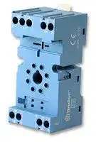
90.02SMA
Relay Socket, DIN Rail, Panel, Screw, 9 Pins, 10 A, 250 V, 90 Series
⚠️ Reference pricing provided. In case of supply shortages, we will connect you with our trusted procurement partners to ensure your project's continuity.
- Manufacturer: FINDER
- Product type: Relay Sockets
- Socket Mounting:DIN Rail, Panel; Socket Terminals:Screw; No. of Pins:9Pins; Current Rating:10A; Voltage Rating:250V; Product Range:-; SVHC:No SVHC (15-Jan-2019); Accessory Type:Socket; Colour:Blue; Con
- SVHC: No SVHC (04-Feb-2026)
- No. of Pins: 9Pins
- Product Range: 90 Series
- Current Rating: 10A
- Voltage Rating: 250V
- Socket Mounting: DIN Rail, Panel
- Socket Terminals: Screw
| Delivery and price | |
|---|---|
| Units per pack | 50 |
| Price | 4.93 € |
| Current stock | 50+ |
| Lead time | 30 days |
Datasheet

60 60 Series - General purpose relays 6 - 10 A SERIES

A

## Features

## 60.12

## 60.13

Plug-in mount 10 A General purpose relay

- 2 & 3 pole changeover contacts

- Cadmium Free contacts (preferred version)

- AC coils & DC coils

- UL Listing (certain relay/socket combinations)

- Contact material options

- Lockable test button with mechanical flag indicator (preferred version)

- 90 series sockets

- Coil EMC suppression

- 2 pole, 10 A power contacts

- 8 pin plug-in

   - 3 pole, 10 A power contacts

   - 11 pin plug-in

- Timer accessories 86 series

- European Patent

## _FOR UL RATINGS SEE:_

_“General technical information” page_ V

||Contact specification||||||||||
|---|---|---|---|---|---|---|---|---|---|---|
||Contact configuration|||||2 CO (DPDT)||||3 CO (3PDT)|
||Rated current/Maximum peak current|||A||10/20||||10/20|
||Rated voltage/Maximum switching voltage|||V AC||250/400||||250/400|
||Rated load AC1|||VA||2,500||||2,500|
||Rated load AC15 (230 V AC)|||VA||500||||500|
||Single phase motor rating (230 V AC)|Single phase motor rating (230 V AC)||kW||0.37||||0.37|
||Breaking capacity DC1: 30/110/220 V||Breaking capacity DC1: 30/110/220 V|A||10/0.4/0.15||||10/0.4/0.15|
||Minimum switching load|mW (V/mA)|mW (V/mA)|||500 (10/5)||||500 (10/5)|
||Standard contact material|||||AgNi||||AgNi|
||Coil specification||||||||||
||Nominal voltage (UN)<br>V AC (50/60 Hz)|||||6 - 12 - 24 - 48 - 60 - 110 - 120 - 230 - 240 - 400|6 - 12 - 24 - 48 - 60 - 110 - 120 - 230 - 240 - 400||||
|||||V DC||6 - 12 - 24 - 48 - 60 - 110 -125 - 220|6 - 12 - 24 - 48 - 60 - 110 -125 - 220||||
||Rated power AC/DC|VA (50 Hz)/W|VA (50 Hz)/W|||2.2/1.3||||2.2/1.3|
||Operating range|||AC||(0.8…1.1)UN||||(0.8…1.1)UN|
|||||DC||(0.8…1.1)UN||||(0.8…1.1)UN|
||Holding voltage||AC/DC||0.8 UN/0.5 UN|||||0.8 UN/0.5 UN|
||Must drop-out voltage||AC/DC||0.2 UN/0.1 UN|||||0.2 UN/0.1 UN|
||Technical data||||||||||
||Mechanical life AC/DC|||cycles|20 · 10<br>6/50 · 10<br>6|||||20 · 10<br>6/50 · 10<br>6|
||Electrical life at rated load AC1|||cycles||200 · 10<br>3||||200 · 10<br>3|
||Operate/release time|||ms||11/4||||11/4|
|IV-2014, www.findernet.com|Insulation between coil and contacts (1.2/50<br>Dielectric strength between open contacts<br>Ambient temperature range<br>Environmental protection<br>Approvals(according to type)|Insulation between coil and contacts (1.2/50µs) kV<br>Dielectric strength between open contacts V AC<br>°C|||CE|4<br>1,000<br>–40…+70<br>RT I<br>G|Hh&~~®@~~|~~®@~~||3.6<br>1,000<br>–40…+70<br>RT I<br>RINA<br>gAYys|


1

60 SERIE S 60 Series - General purpose relays 6 - 10 A

## Features

## 60.12 - 5200

## 60.13 - 5200

Plug-in mount - 6 A

A Bifurcated contacts for low level switching

- 2 & 3 pole changeover contacts

- Cadmium Free contacts (Gold plated Silver Nickel)

- AC coils & DC coils

- Lockable test button with mechanical flag indicator (preferred version)

- 90 series sockets

- Coil EMC suppression

- Timer accessories 86 series

- European Patent

- 2 pole, 6 A bifurcated contacts

- 8 pin plug-in

- 3 pole, 6 A bifurcated contacts

- 11 pin plug-in

## _FOR UL RATINGS SEE:_

_“General technical information” page_ V

|Contact specification|||||||||||
|---|---|---|---|---|---|---|---|---|---|---|
|Contact configuration|||||2 CO (DPDT)|||3 CO (3PDT)|||
|Rated current/Maximumpeak current|||A||6/10|||6/10|||
|Rated voltage/Maximum switching voltage|||V AC||250/400|||250/400|||
|Rated load AC1|||VA||1,500|||1,500|||
|Rated load AC15 (230 V AC)|||VA||250|||250|||
|Single phase motor rating (230 V AC)|Single phase motor rating (230 V AC)||kW||0.185|||0.185|||
|Breaking capacity DC1: 30/110/220 V||Breaking capacity DC1: 30/110/220 V|A||6/0.3/0.12|||6/0.3/0.12|||
|Minimum switching load|mW (V/mA)|mW (V/mA)|||50 (5/5)|||50 (5/5)|||
|Standard contact material||||AgNi + Au bifurcated contacts|AgNi + Au bifurcated contacts|||AgNi + Au bifurcated contacts|||
|Coil specification|||||||||||
|Nominal voltage (UN)<br>V AC (50/60 Hz)|||||6 - 12 - 24 - 48 - 60 - 110 - 120 - 230 - 240 - 400|6 - 12 - 24 - 48 - 60 - 110 - 120 - 230 - 240 - 400|||||
||||V DC||6 - 12 - 24 - 48 - 60 - 110 -125 - 220|6 - 12 - 24 - 48 - 60 - 110 -125 - 220|||||
|Rated power AC/DC|VA (50 Hz)/W|VA (50 Hz)/W|||2.2/1.3|||2.2/1.3|||
|Operating range|||AC||(0.8…1.1)UN|||(0.8…1.1)UN|||
||||DC||(0.8…1.1)UN|||(0.8…1.1)UN|||
|Holding voltage||AC/DC||0.8 UN/0.5 UN||||0.8 UN/0.5 UN|||
|Must drop-out voltage||AC/DC||0.2 UN/0.1 UN||||0.2 UN/0.1 UN|||
|Technical data|||||||||||
|Mechanical life AC/DC|||cycles|20 · 10<br>6/50 · 10<br>6||||20 · 10<br>6/50 · 10<br>6|||
|Electrical life at rated load AC1|||cycles||250 · 10<br>3|||250 · 10<br>3|||
|Operate/release time|||ms||11/4|||11/4|||
|Insulation between coil and contacts (1.2/50µs) kV<br>Dielectric strength between open contacts<br>V AC<br>Ambient temperature range<br>°C<br>Environmental protection<br>Approvals(according to type)||||kV<br>CE|4<br>1,000<br>–40…+70<br>RT I<br>@|FAL&~~9)~~|~~9)~~|3.6<br>1,000<br>–40…+70<br>RT I<br>RINA<br>AXys||IV-2014, www.findernet.com|


2

60 SERIES

60 Series - General purpose relays 6 - 10 A

A

## Features

## 60.62

**==> picture [27 x 9] intentionally omitted <==**

**----- Start of picture text -----**<br>
60.63<br>**----- End of picture text -----**<br>


Flange mount - General purpose relay 10 A

- Faston 187, 4.8x0.8 mm

- 2 & 3 pole changeover contacts

- AC coils & DC coils

- Cadmium Free contacts

- Contacts material options

- 2 pole, 10 A power contacts

- Flange mount/Faston 187

- 3 pole, 10 A power contacts

- Flange mount/Faston 187

_FOR UL RATINGS SEE: “General technical information” page_ V

||Contact specification|||||||||||
|---|---|---|---|---|---|---|---|---|---|---|---|
||Contact configuration|||||2 CO (DPDT)||||3 CO (3PDT)|3 CO (3PDT)|
||Rated current/Maximumpeak current|||A||10/20|||||10/20|
||Rated voltage/Maximum switching voltage|||V AC||250/400||||250/400||
||Rated load AC1|||VA|VA|2,500|||||2,500|
||Rated load AC15 (230 V AC)|||VA||500|||||500|
||Single phase motor rating (230 V AC)|Single phase motor rating (230 V AC)||kW||0.37|||||0.37|
||Breaking capacity DC1: 30/110/220 V||Breaking capacity DC1: 30/110/220 V|A||10/0.4/0.15||||10/0.4/0.15||
||Minimum switching load|mW (V/mA)|mW (V/mA)|||500 (10/5)||||500 (10/5)||
||Standard contact material|||||AgNi|||||AgNi|
||Coil specification|||||||||||
||Nominal voltage (UN)<br>V AC (50/60 Hz)|||||6 - 12 - 24 - 48 - 60 - 110 - 120 - 230 - 240 - 400|6 - 12 - 24 - 48 - 60 - 110 - 120 - 230 - 240 - 400|||||
|||||V DC||6 - 12 - 24 - 48 - 60 - 110 -125 - 220|6 - 12 - 24 - 48 - 60 - 110 -125 - 220|||||
||Rated power AC/DC|VA (50 Hz)/W|VA (50 Hz)/W|||2.2/1.3|||||2.2/1.3|
||Operating range|||AC||(0.8…1.1)UN||||(0.8…1.1)UN||
|||||DC||(0.8…1.1)UN||||(0.8…1.1)UN||
||Holding voltage||AC/DC||0.8 UN/0.5 UN|||||0.8 U|0.8 UN/0.5 UN|
||Must drop-out voltage||AC/DC||0.2 UN/0.1 UN|||||0.2 U|0.2 UN/0.1 UN|
||Technical data|||||||||||
||Mechanical life AC/DC|||cycles|20 · 10<br>6/50 · 10<br>6|||||20 · 10|20 · 10<br>6/50 · 10<br>6|
||Electrical life at rated load AC1|||cycles||200 · 10<br>3||||200 · 10<br>3||
||Operate/release time|||ms||11/4|||||11/4|
|IV-2014, www.findernet.com|Insulation between coil and contacts (1.2/50µs) kV<br>Dielectric strength between open contacts<br>V AC<br>Ambient temperature range<br>°C<br>Environmental protection<br>Approvals(according to type)||||kV<br>C€|4<br>1,000<br>–40…+70<br>RT I<br>~~GHG~~ ~~®@~~||||3.6<br>1,000<br>–40…+70<br>RT I<br>RINA<br>_ANus||


3

60 SERIE S

60 Series - General purpose relays 6 - 10 A

## Ordering information

Example: 60 series plug-in relay, 3 CO (3PDT), 12 V DC coil, test button and mechanical indicator.

A A B C D 6 0 . 1 3 . 9 . 0 1 2 . 0 0 4 0 Len Hoe Series A: Contact material D: Special versions 0 = Standard Type 1 = 8/11 pin plug-in 5 = AgNi + Au C: Options 6 = Faston 187 (4.8x0.8 mm) B: Contact circuit 0 with flange mount 0 = CO (nPDT) 2 No. of poles 2 = Bifurcated contacts 3 2 = 2 pole 60.12/13 - 6 A only 4 3 = 3 pole 5* Coil version ~~—~~ 7 4 = Current sensing (60.12/13 only)

D: Special versions

- 0 = Standard

C: Options

- 0 = None

- 2 = Mechanical indicator

- 3 = LED (AC) 4 = Lockable test button + mechanical indicator

- 5* = Lockable test button + LED (AC) 54* = Lockable test button + LED (AC) + mechanical indicator

8 = AC (50/60 Hz)

- 6* = LED + diode (DC, polarity positive to pin 2)

9 = DC

- 7* = Lockable test button + LED + diode

Coil voltage See coil specifications

   - (DC, polarity positive to pin 2)

- 74* = Lockable test button + LED + diode (DC, polarity positive to pin 2) + mechanical indicator

- Options not available for 220 V DC and 400 V AC versions.

**==> picture [508 x 456] intentionally omitted <==**

**----- Start of picture text -----**<br>
Selecting features and options: only combinations in the same row are possible. 400 V AC versions.<br>Preferred selections for best availability are shown in bold.<br>Type Coil version A B C D<br>60.12/13 rs AC 0 0 0 - 2 - 3 -  4  - 5 0<br>AC 0 0 54 /<br>AC 5 0 - 2 0 - 2 - 3 - 4 - 5 0<br>AC 5 0 - 2 54 /<br>DC 0 0 0 - 2 -  4  - 6 - 7 0<br>DC 0 0 74 /<br>DC 5 0 - 2 0 - 2 - 4 - 6 - 7 0<br>rs<br>DC 5 0 - 2 74 /<br>rs current sensing 0 0 4 0<br>[===> 60.62/63 AC-DC ee 0 - 5 0 ee 0 ee 0<br>Descriptions: Options and Special versions<br>C: Option 3, 5, 54 C: Option 6, 7, 74<br>LED (AC) LED + diode (DC, polarity<br>positive to pin 2)<br>Lockable test button and mechanical flag indicator (0040, 0050, 0054, 0070, 0074)<br>1 3 The dual-purpose Finder test button can be used in two ways:<br>Case 1) The plastic pip (located directly above the test button) remains intact. In this case, when the<br>test button is pushed, the contacts operate. When the test button is released the contacts return to their<br>former state.<br>Case 2) The plastic pip is broken-off (using an appropriate cutting tool). In this case, (in addition to<br>the above function), when the test button is pushed and rotated, the contacts are latched in the<br>operating state, and remain so until the test button is rotated back to its former position.<br>y In both cases ensure that the test button actuation is swift and decisive.<br>2<br>y -<br>P E A<br>P A T E N T<br>RO N<br>EU UE<br>NA E POR<br>**----- End of picture text -----**<br>


Case 2) The plastic pip is broken-off (using an appropriate cutting tool). In this case, (in addition to the above function), when the test button is pushed and rotated, the contacts are latched in the operating state, and remain so until the test button is rotated back to its former position. In both cases ensure that the test button actuation is swift and decisive.

4

60 SERIES

60 Series - General purpose relays 6 - 10 A

## Technical data

|Insulation according to EN 61810-1|Insulation according to EN 61810-1|2 pole|2 pole|3 pole|3 pole|
|---|---|---|---|---|---|
|Nominal voltage of supplysystem<br>V AC||230/400||230/400||
|Rated insulation voltage<br>V AC||250|400|250|400|
|Pollution degree||3|2|3|2|
|Insulation between coil and contact set||||||
|Type of insulation||Basic||Basic||
|Overvoltage category||III||III||
|Rated impulse voltage<br>kV(1.2/50µs)||4||3.6||
|Dielectric strength<br>V AC||2,000||2,000||
|Insulation between adjacent contacts||||||
|Type of insulation||Basic||Basic||
|Overvoltage category||III||III||
|Rated impulse voltage<br>kV(1.2/50µs)||4||3.6||
|Dielectric strength<br>V AC||2,000||2,000||
|Insulation between open contacts||||||
|Type of disconnection||Micro-disconnection||Micro-disconnection||
|Dielectric strength<br>V AC/kV (1.2/50 µs)||1,000/1.5||1,000/1.5||
|Conducted disturbance immunity||||||
|Burst(5...50)ns, 5 kHz, on A1 - A2<br>Surge (1.2/50 µs) on A1 - A2 (differential mode)||EN 61000-4-4||level 4(4 kV)||
|||EN 61000-4-5||level 4 (4 kV)||
|Other data||||||
|Bounce time: NO/NC<br>ms||1/4||||
|Vibration resistance(5…55)Hz: NO/NC<br>g||22/22||||
|Shock resistance|g|20||||
|Power lost to the environment|without contact current<br>W<br>with rated current<br>W|1.3||1.3||
|||2.7 (60.12, 60.62)||3.4 (60.13, 60.63)||


## Contact specification

F 60 - Electrical life (AC) v contact current

**==> picture [251 x 140] intentionally omitted <==**

**----- Start of picture text -----**<br>
Resistive load - cosϕ = 1<br>Cycles Inductive load - cosϕ = 0.4<br>**----- End of picture text -----**<br>


## H 60 - Maximum DC1 breaking capacity

**==> picture [250 x 140] intentionally omitted <==**

**----- Start of picture text -----**<br>
contacts in series<br>DC voltage (V)<br>DC breaking current (A)<br>**----- End of picture text -----**<br>


- When switching a resistive load (DC1) having voltage and current values under the curve, an electrical life of ≥ 100·103 can be expected.

- In the case of DC13 loads, the connection of a diode in parallel with the load will permit a similar electrical life as for a DC1 load. Note: the release time for the load will be increased.

## Coil specifications

## DC coil data

|IV-2014, www.findernet.com|Nominal<br>voltage<br>UN|Coil<br>code|Operating range<br>Umin<br>Umax|Operating range<br>Umin<br>Umax|Resistance<br>R|Rated coil<br>consumption<br>Iat UN|
|---|---|---|---|---|---|---|
||V||V|V|Ω|mA|
||6|9.006|4.8|6.6|28|214|
||12|9.012|9.6|13.2|110|109|
||24|9.024|19.2|26.4|445|53.9|
||48|9.048|38.4|52.8|1,770|27.1|
||60|9.060|48|66|2,760|21.7|
||110|9.110|88|121|9,420|11.7|
||125|9.125|100|138|12,000|10.4|
||220|9.220|176|242|37,300|5.8|


## AC coil data

|Nominal<br>voltage<br>UN|Coil<br>code|Operating range<br>Umin<br>Umax|Operating range<br>Umin<br>Umax|Resistance <br>R|Rated coil<br>consumption<br>Iat UN(50Hz)|
|---|---|---|---|---|---|
|V||V|V|Ω|mA|
|6|8.006|4.8|6.6|4.6|367|
|12|8.012|9.6|13.2|19|183|
|24|8.024|19.2|26.4|74|90|
|48|8.048|38.4|52.8|290|47|
|60|8.060|48|66|450|37|
|110|8.110|88|121|1,600|20|
|120|8.120|96|132|1,940|18.6|
|230|8.230|184|253|7,250|10.5|
|240|8.240|192|264|8,500|9.2|
|400|8.400|320|440|19,800|6|


5

60 SERIE S 60 Series - General purpose relays 6 - 10 A

## Coil specifications

R 60 - DC coil operating range v ambient temperature

R 60 - AC coil operating range v ambient temperature

A

1 - Max. permitted coil voltage.

2 - Min. pick-up voltage with coil at ambient temperature.

1 - Max. permitted coil voltage.

2 - Min. pick-up voltage with coil at ambient temperature.

## Current sensing version

## Current sensing DC coil data

**==> picture [7 x 132] intentionally omitted <==**

**----- Start of picture text -----**<br>
L<br>N<br>**----- End of picture text -----**<br>


Typical application with current sensing relays. An open circuit filiment of lamp L1 is detected by the current sensing relay coil (K1)  which causes the back-up safety lamp L2 to be energised, and indication of failure at the control panel via lamp S1. Example: navigation light.

L1 = Light L2 = Safety light S1= Control light K1 = Relay

**==> picture [246 x 269] intentionally omitted <==**

**----- Start of picture text -----**<br>
|||||||
|---|---|---|---|---|---|
|Coil code|Imin|(A)|IN (A)|Imax (A)|R (Ω)|
|4202|1.7|2.0|2.4|0.15|
|4182|1.5|1.8|2.2|0.19|
|4162|1.4|1.6|1.9|0.24|
|4142|1.2|1.4|1.7|0.31|
|4122|1.0|1.2|1.4|0.42|
|4102|0.85|1.0|1.2|0.61|
|4092|0.8|0.9|1.1|0.75|
|4062|0.5|0.6|0.7|1.70|
|4032|0.25|0.3|0.4|6.70|
|4012|0.085|0.1|0.15|61|
|Current sensing AC coil data|
|Coil code|Imin|(A)|IN (A)|Imax (A)|R (Ω)|
|4251|2.1|2.5|3.0|0.05|
|4181|1.5|1.8|2.2|0.10|
|4161|1.4|1.6|1.9|0.12|
|4121|1.0|1.2|1.4|0.22|
|4101|0.85|1.0|1.2|0.32|
|4051|0.42|0.5|0.6|1.28|
|4041|0.34|0.4|0.5|2.00|
|4031|0.25|0.3|0.4|3.57|
|4021|0.17|0.2|0.25|8.0|
|4011|0.085|0.1|0.15|32.1|

**----- End of picture text -----**<br>


Other types of current sensing relays are available on request.

Accessories

Sheet of marker tags for relay types 60.12 and 60.13, plastic, 72 tags, 6x12 mm 060.72

060.72

6

60 90 Series - Socket overview for 60 series relays SERIES Module Socket Relay Description Mounting Accessories 99.02 90.02 60.12 Screw terminal (Box clamp) socket Panel or 35 mm rail - Coil indication and EMC 90.03 60.13 Double A1 terminal (EN 60715) mount suppression modules A - Jumper link - Timer modules 90.03 - Metal retaining clip See page 8 ~~i~~ Module Socket Relay Description Mounting Accessories 99.01 90.20 60.12 Screw terminal (Box clamp) socket Panel or 35 mm rail - Coil indication and EMC 90.21 60.13 (EN 60715) mount suppression modules - Metal retaining clip ~ ~~.~~ 90.21 ~~[i]~~ See page 9 Module Socket Relay Description Mounting Accessories — 90.82.3 60.12 Screw terminal (Box clamp) socket Panel or 35 mm rail - Metal retaining clip — 90.83.3 60.13 (EN 60715) mount 90.83.3 See page 10 Module Socket Relay Description Mounting Accessories — 90.22 60.12 Screw terminal (Box clamp) socket Panel or 35 mm rail - Metal retaining clip — 90.23 60.13 (EN 60715) mount ~~=~~ 90.23 See page 10 Module Socket Relay Description Mounting Accessories — 90.26 60.12 Screw terminal (Plate clamp) socket Panel or 35 mm rail - Metal retaining clip — 90.27 60.13 (EN 60715) mount 90.26 See page 11 Module Socket Relay Description Mounting Accessories — 90.12 60.12 Flange mount solder socket M3 screw fixing — — 90.13 60.13 ~~_~~ 90.12 ~~ESS~~ See page 1 Module Socket Relay Description Mounting Accessories — 90.14 60.12 PCB socket PCB — — 90.14.1 60.12 ~~:~~ 90.15 — 90.15 60.13 — 90.15.1 60.13 See page 12 ~~= |~~ lt

7

60 SERIE S 90 Series - Sockets and accessories for 60 series relays

**==> picture [501 x 218] intentionally omitted <==**

**----- Start of picture text -----**<br>
|||||||
|---|---|---|---|---|---|
|Screw terminal (Box clamp) socket|90.02|90.02.0|90.03|90.03.0|
|panel or 35 mm rail (EN 60715) mount|Blue|Black|Blue|Black|
|A|For relay type|60.12|60.13|
|Accessories|
|Metal retaining clip|090.33|
|90.03|6-way|jumper link|090.06|
|Approvals|Identification tag|090.00.2|
|(according to type):|Modules (see table below)|99.02|
|C€|GHA &|Timer modules (see table below)|86.00, 86.30|
|Technical data|
|@|Ais|Rated values|10 A - 250 V|
|Dielectric strength|2 kV AC|
|Protection category|IP 20|
|et) us|Certain relay/socketcombinations|Ambient temperature|°C|–40...+70|
|©|Screw torque|Nm|0.6|
|Wire|strip length|mm|10|
|Max. wire size for 90.02 and 90.03 sockets|Po|solid|wire|stranded|wire|
|mm2|Po|1x6 / 2x2.5|1x4 / 2x2.5|
|AWG|Po|1x10 / 2x14|1x12 / 2x14|

**----- End of picture text -----**<br>


**==> picture [521 x 391] intentionally omitted <==**

**----- Start of picture text -----**<br>
|||||||||||||||||
|---|---|---|---|---|---|---|---|---|---|---|---|---|---|---|---|
|a|a|.|
|6-way jumper link|for 90.02 and 90.03 sockets|090.06 (blue)|090.06.0 (black)|
|3s|LN|Rated values|10 A - 250 V|2.|
|ee|ca|NALA|
|090.06|Approvals|
|(according to type):|@|FAL|SAdus|“aia|
|s a)|:|49.5|15|||23|||15|||23|||15|49.5|[|128|||
|86 series timer modules|
|86.00|Multi-voltage: (12…240)V AC/DC;|
|Multi-functions: AI, DI, SW, BE, CE, DE, EE, FE;|(0.05 s…100 h)|86.00.0.240.0000|
|(12…24)V AC/DC; Bi-function: AI, DI;|(0.05 s…100 h)|86.30.0.024.0000|
|(110...125)V AC; Bi-function: AI, DI;|(0.05s…100h)|86.30.8.120.0000|
|(230...240)V AC; Bi-function: AI, DI;|(0.05 s…100 h)|86.30.8.240.0000|
|Approvals (according to type):|
|86.30|
|99.02 coil indication and EMC suppression modules|for 90.02 and 90.03 sockets|
|Diode (+A1, standard polarity)|(6...220)V DC|99.02.3.000.00|
|LED|(6...24)V DC/AC|99.02.0.024.59|
|LED|(28...60)V DC/AC|99.02.0.060.59|
|99.02|“Bi|LED|(110...240)V DC/AC|99.02.0.230.59|
|LED + Diode (+A1, standard polarity)|(6...24)V DC|99.02.9.024.99|
|Approvals|LED + Diode (+A1, standard polarity)|(28...60)V DC|99.02.9.060.99|
|(according to type):|LED + Diode (+A1, standard polarity)|(110...220)V DC|99.02.9.220.99|
|EAL|&|As|LED + Varistor|(6...24)V DC/AC|99.02.0.024.98|
|LED + Varistor|(28...60)V DC/AC|99.02.0.060.98|
|LED + Varistor|(110...240)V DC/AC|99.02.0.230.98|
|RC circuit|(6...24)V DC/AC|99.02.0.024.09|
|DC Modules with|RC circuit|(28...60)V DC/AC|99.02.0.060.09|
|non-standard polarity|RC circuit|(110...240)V DC/AC|99.02.0.230.09|
|(+A2) on request.|Residual current by-pass|(110...240)V AC|99.02.8.230.07|
|E|

**----- End of picture text -----**<br>


8

60 90 Series - Sockets and accessories for 60 series relays SERIES

**==> picture [19 x 7] intentionally omitted <==**

**----- Start of picture text -----**<br>
90.21<br>**----- End of picture text -----**<br>


Approvals (according to type):

|Screw terminal (Box clamp) socket<br>panel or 35 mm rail (EN 60715) mount<br>For relay type<br>Accessories<br>Metal retainingclip (supplied with socket -packagingcode SMA)|90.20<br>90.20.0<br>90.21<br>90.21.0<br>Blue<br>Black<br>Blue<br>Black<br>60.12<br>60.13<br>090.33|90.20<br>90.20.0<br>90.21<br>90.21.0<br>Blue<br>Black<br>Blue<br>Black<br>60.12<br>60.13<br>090.33|
|---|---|---|
|Modules (see table below)<br>Technical data<br>Rated values<br>Dielectric strength|99.01<br>10 A - 250 V<br>2 kV AC||
|Dielectric strength|2 kV AC||
|Protection category|IP 20||
|Ambient temperature<br>°C<br>S~~c~~rew torque<br>Nm|–40…+70<br>0.5||
|S~~c~~rew torque<br>Nm<br>Wire striplength<br>mm|0.5<br>10||
|Max. wire size for 90.20 and 90.21 sockets<br>mm<br>2<br>AWG|solid wire<br>stranded wire|stranded wire|
||1x6/2x2.5<br>1x6|1x6/2x2.5|
||1x10 / 2x14<br>1x10 / 2x14|1x10 / 2x14|


**==> picture [177 x 7] intentionally omitted <==**

**----- Start of picture text -----**<br>
90.20 90.21<br>**----- End of picture text -----**<br>


## 99.01

Approvals (according to type):

*Modules in Black housing are available on request.

Green LED is standard. Red LED available on request.

|See technical datapage 215/216<br>Blue*|Blue*|
|---|---|
|Diode(+A1,standardpolarity)<br>(6...220)V DC<br>99.01.3.000.00|99.01.3.000.00|
|Diode(+A2,non-standardpolarity)<br>(6...220)V DC<br>99.01.2.000.00|99.01.2.000.00|
|(6...24)V DC/AC<br>99.01.0.024.59|99.01.0.024.59|
|(28...60)V DC/AC<br>99.01.0.060.59|99.01.0.060.59|
|(110...240)V DC/AC<br>99.01.0.230.59|99.01.0.230.59|
|LED + Diode(+A1,standardpolarity)<br>(6...24)V DC<br>99.01.9.024.99|99.01.9.024.99|
|LED + Diode(+A1,standardpolarity)<br>(28...60)V DC<br>99.01.9.060.99|99.01.9.060.99|
|(,py)<br>()<br>LED + Diode(+A1,standardpolarity)<br>(110...220)V DC<br>99.01.9.220.99|99.01.9.220.99|
|LED + Diode(+A2,non-standardpolarity)<br>(6...24)V DC<br>99.01.9.024.79|99.01.9.024.79|
|LED + Diode(+A2,non-standardpolarity)<br>(28...60)V DC<br>99.01.9.060.79|99.01.9.060.79|
|LED + Diode(+A2,non-standardpolarity)<br>(110...220)V DC<br>99.01.9.220.79|99.01.9.220.79|
|LED + Varistor<br>(6...24)V DC/AC<br>99.01.0.024.98|99.01.0.024.98|
|LED + Varistor<br>(28...60)V DC/AC<br>99.01.0.060.98|99.01.0.060.98|
|LED + Varistor<br>(110...240)V DC/AC<br>99.01.0.230.98|99.01.0.230.98|
|RC circuit<br>(6...24)V DC/AC<br>99.01.0.024.09|99.01.0.024.09|
|RC circuit<br>(28...60)V DC/AC<br>99.01.0.060.09|99.01.0.060.09|
|RC circuit<br>(110...240)V DC/AC<br>99.01.0.230.09|99.01.0.230.09|
|Residual current by-pass<br>(110...240)V AC<br>99.01.8.230.07|99.01.8.230.07|


9

60 SERIE S 90 Series - Sockets and accessories for 60 series relays

**==> picture [10 x 13] intentionally omitted <==**

**----- Start of picture text -----**<br>
A<br>**----- End of picture text -----**<br>


**==> picture [69 x 29] intentionally omitted <==**

**----- Start of picture text -----**<br>
90.83.3<br>Approvals<br>(according to type):<br>**----- End of picture text -----**<br>


|Screw terminal (Box clamp) socket<br>panel or 35 mm rail (EN 60715) mount<br>For relay type<br>Accessories<br>Metal retaining clip<br>Technical data<br>Rated values|90.82.3<br>90.82.30<br>90.83.3<br>90.83.30<br>Blue<br>Black<br>Blue<br>Black<br>60.12<br>60.13<br>090.33<br>10 A - 250 V|90.82.3<br>90.82.30<br>90.83.3<br>90.83.30<br>Blue<br>Black<br>Blue<br>Black<br>60.12<br>60.13<br>090.33<br>10 A - 250 V|
|---|---|---|
|Dielectric strength|2 kV AC||
|Protection category|IP 20||
|gy<br>Ambient temperature<br>S~~c~~rew torque|°C –40…+70<br>Nm0.8||
|S~~c~~rew torque<br>Max. wire size for 90.82.3 and 90.83.3 sockets|Nm 0.8<br>solid wire<br>stranded wire||
||mm<br>2 1x6/2x4<br>1x6|1x6/2x4|
||AWG 1x10 / 2x14<br>1x10 / 2x14|1x10 / 2x14|


**==> picture [197 x 6] intentionally omitted <==**

**----- Start of picture text -----**<br>
90.82.3 90.83.3<br>**----- End of picture text -----**<br>


|Screw (Box clamp) terminal socket<br>panel or 35 mm rail (EN60715) mount<br>For relay type<br>Accessories<br>Metal retaining clip (supplied with socket - packaging code SMA)<br>Technical data<br>Rated values|90.22<br>90.23<br>Blue<br>Blue<br>60.12<br>60.13<br>Metal retaining clip (supplied with socket - packaging code SMA)<br>090.33<br>10 A - 250 V|90.22<br>90.23<br>Blue<br>Blue<br>60.12<br>60.13<br>Metal retaining clip (supplied with socket - packaging code SMA)<br>090.33<br>10 A - 250 V|
|---|---|---|
|Dielectric strength|2 kV AC||
|Protection category|IP 20||
|Ambient temperature<br>S~~c~~rew torque|°C<br>–40…+70<br>Nm<br>0.5||
|S~~c~~rew torque<br>Wire striplength|Nm<br>0.5<br>mm<br>7||
|Max wire size for 90.22 and 90.23 sockets|solid wire<br>stranded wire|stranded wire|
||mm<br>2<br>1x6/2x2.5<br>1x6|1x6/2x2.5|
||AWG<br>1x10 / 2x14<br>1x10 / 2x14|1x10 / 2x14|


**==> picture [20 x 6] intentionally omitted <==**

**----- Start of picture text -----**<br>
90.22<br>**----- End of picture text -----**<br>


**==> picture [21 x 6] intentionally omitted <==**

**----- Start of picture text -----**<br>
90.23<br>**----- End of picture text -----**<br>


10

60 90 Series - Sockets and accessories for 60 series relays SERIES

**==> picture [19 x 7] intentionally omitted <==**

**----- Start of picture text -----**<br>
90.26<br>**----- End of picture text -----**<br>


Approvals (according to type):

**==> picture [19 x 6] intentionally omitted <==**

**----- Start of picture text -----**<br>
90.12<br>**----- End of picture text -----**<br>


Approvals (according to type):

|Screw terminal (Plate clamp) socket<br>panel or 35 mm rail (EN 60715) mount<br>For relay type<br>Accessories<br>Metal retaining clip (supplied with socket - packaging code SMA)<br>Technical data<br>Rated values|90.26<br>90.26.0<br>90.27<br>90.27.0<br>Blue<br>Black<br>Blue<br>Black<br>60.12<br>60.13<br>Metal retaining clip (supplied with socket - packaging code SMA)<br>090.33<br>10 A - 250 V|90.26<br>90.26.0<br>90.27<br>90.27.0<br>Blue<br>Black<br>Blue<br>Black<br>60.12<br>60.13<br>Metal retaining clip (supplied with socket - packaging code SMA)<br>090.33<br>10 A - 250 V|
|---|---|---|
|Dielectric strength|2 kV AC||
|Protection category|IP 20||
|Ambient temperature<br>Screw torque<br>Nm|°C<br>–40…+70<br>Nm<br>0.8||
|Screw torque<br>Nm<br>Wire striplength<br>mm|Nm<br>0.8<br>mm<br>10||
|Max. wire size for 90.26 and 90.27 sockets<br>mm<br>AWG|solid wire<br>stranded wire|stranded wire|
||mm<br>2<br>1x4/2x2.5<br>1x4|1x4/2x2.5|
||AWG<br>1x12 / 2x14<br>1x12 / 2x14|1x12 / 2x14|


**==> picture [20 x 7] intentionally omitted <==**

**----- Start of picture text -----**<br>
90.27<br>**----- End of picture text -----**<br>


**==> picture [20 x 7] intentionally omitted <==**

**----- Start of picture text -----**<br>
90.26<br>**----- End of picture text -----**<br>


|Flange mount solder socketmount with M3 screw<br>For relay type<br>Technical data<br>Rated values|90.12 (black)<br>90.13 (black)<br>60.12<br>60.13<br>10 A - 250 V|
|---|---|
|Dielectric strength|2 kV AC|
|Ambient temperature|°C<br>–40…+70|


**==> picture [11 x 13] intentionally omitted <==**

**----- Start of picture text -----**<br>
A<br>**----- End of picture text -----**<br>


11

60 SERIE S 90 Series - Sockets and accessories for 60 series relays

**==> picture [10 x 13] intentionally omitted <==**

**----- Start of picture text -----**<br>
A<br>**----- End of picture text -----**<br>


**==> picture [70 x 32] intentionally omitted <==**

**----- Start of picture text -----**<br>
90.15<br>Approvals<br>(according to type):<br>**----- End of picture text -----**<br>


|PCB socket|Blue|90.14 (Ø 20.5 mm)|90.14 (Ø 20.5 mm)|90.15 (Ø 22 mm)|
|---|---|---|---|---|
||Blue|90.14.1 (Ø 17.5 mm)||90.15.1 (Ø 19 mm)|
|For relay type||60.12||60.13|
|Technical data|||||
|Rated values||10 A - 250 V|||
|Dielectric strength||2 kV AC|||
|Ambient temperature<br>5|°C|–40…+70<br>~~27~~|~~28~~|~~18.5~~|


**==> picture [123 x 7] intentionally omitted <==**

**----- Start of picture text -----**<br>
90.14 90.15<br>**----- End of picture text -----**<br>


## Packaging code

How to code and identify retaining clip and packaging options for sockets.

Example:

9 0 . 2 1 S M A A Standard packaging SM Metal retaining clip ~~To~~ [_ 9 0 . 2 1 Without retaining clip IE JL LJ

12
Updated at June 6, 2026
About Novapart
Novapart is a B2B electronic component broker specialising in stock shortages and cost reduction. We source hard-to-find parts and identify compliant alternatives across a catalogue of 410,000+ components from 500+ manufacturers.
Learn more →Stock Shortage Specialist
When a component is unavailable, discontinued or has an unacceptable lead time, we tap into our network of vetted European and Asian distributors to source what you need — without compromising on quality or traceability.
Request a quote →Compliant Alternatives
We identify pin-to-pin, electrically equivalent substitutes that meet the same certifications (RoHS, AEC-Q100, REACH) as your original specification — validated against datasheets, not just part numbers. Often at a lower cost.
BOM Analysis service →