
Image not available
Illustrative purposes only

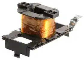
9-3185-1
AC COIL, 110/120VAC
⚠️ Reference pricing provided. In case of supply shortages, we will connect you with our trusted procurement partners to ensure your project's continuity.
- Manufacturer: EATON CUTLER HAMMER
- Product type: Other Relay Accessories
- Accessory Type: AC Coil
| Delivery and price | |
|---|---|
| Units per pack | 5 |
| Price | 152.78 € |
| Current stock | 10+ |
| Lead time | 7 days |
Datasheet

## Definite Purpose Contactors and Starters

## **0–40A Compact Contactor**

## **25–60A Starter**

## **Heavy-Duty Special Purpose**

|**4.1**|**Product Overview—Contactors and Starters**<br>Product Overview  . . . . . . . . . . . . . . . . . . . . . . . . . . . . . . . . . . . . . . . .|**V5-T4-2**|**4**|
|---|---|---|---|
||Application Description  . . . . . . . . . . . . . . . . . . . . . . . . . . . . . . . . . . . .|**V5-T4-2**|**4**|
||Catalogue Number Selection . . . . . . . . . . . . . . . . . . . . . . . . . . . . . . . .|**V5-T4-3**|**4**|
|**4.2**|**Contactors**|||
||20–40A, Compact Single- and Two-Pole—C25  . . . . . . . . . . . . . . . . . .|**V5-T4-4**|**4**|
|=|15–360A, Two-, Three- and Four-Pole—C25 . . . . . . . . . . . . . . . . . . . . .<br>Accessories . . . . . . . . . . . . . . . . . . . . . . . . . . . . . . . . . . . . . . . . . . . . .|**V5-T4-8**<br>**V5-T4-11**|**4**|
||15–40A, Three-Pole Fuse Block . . . . . . . . . . . . . . . . . . . . . . . . . . . . . .|**V5-T4-17**|**4**|
||15–75A, Reversing and Two-Speed—C65 . . . . . . . . . . . . . . . . . . . . . .|**V5-T4-20**||
|**4.3**|**Starters**||**4**|
||25–60A, Single- and Three-Phase—A25, B25  . . . . . . . . . . . . . . . . . . .|**V5-T4-23**|**4**|
||15–45A, Single- and Three-Phase—A27, B27  . . . . . . . . . . . . . . . . . . .<br>15–75A, Single- and Three-Phase—A30, B30 and|**V5-T4-30**|**4**|
||C440/XT Electronic Overload Relay . . . . . . . . . . . . . . . . . . . . . . . . . .|**V5-T4-38**|**4**|
|**4.4**|**NEMA Type 1 Enclosed Control**|||
||15–60A Contactors—C25  . . . . . . . . . . . . . . . . . . . . . . . . . . . . . . . . . .|**V5-T4-46**|**4**|
||25–60A Starters—A25, B25  . . . . . . . . . . . . . . . . . . . . . . . . . . . . . . . .<br>15–45A Starters—A27, B27 . . . . . . . . . . . . . . . . . . . . . . . . . . . . . . . . .|**V5-T4-49**<br>**V5-T4-52**|**4**|
||Accessories . . . . . . . . . . . . . . . . . . . . . . . . . . . . . . . . . . . . . . . . . . . . .<br>Options  . . . . . . . . . . . . . . . . . . . . . . . . . . . . . . . . . . . . . . . . . . . . . . . .<br>Technical Data and Specifications  . . . . . . . . . . . . . . . . . . . . . . . . . . . .|**V5-T4-55**<br>**V5-T4-57**<br>**V5-T4-58**|**4**<br>**4**|
|**4.5**|**Renewal Parts**<br>Product Selection||**4**|
||Contact Kits, Coils . . . . . . . . . . . . . . . . . . . . . . . . . . . . . . . . . . . . . .|**V5-T4-59**|**4**|
|**4.6**|**Heavy-Duty Special Purpose Contactors**<br>Product Selection . . . . . . . . . . . . . . . . . . . . . . . . . . . . . . . . . . . . . . . . .|**V5-T4-64**|**4**|
||Accessories . . . . . . . . . . . . . . . . . . . . . . . . . . . . . . . . . . . . . . . . . . . . .|**V5-T4-64**|**4**|
||Renewal Parts  . . . . . . . . . . . . . . . . . . . . . . . . . . . . . . . . . . . . . . . . . . .<br>Technical Data and Specifications  . . . . . . . . . . . . . . . . . . . . . . . . . . . .<br>Dimensions  . . . . . . . . . . . . . . . . . . . . . . . . . . . . . . . . . . . . . . . . . . . . .|**V5-T4-65**<br>**V5-T4-65**<br>**V5-T4-66**|**4**<br>**4**|
|**4.7**|**Direct Current Contactors**||**4**|
||600V Contactors  . . . . . . . . . . . . . . . . . . . . . . . . . . . . . . . . . . . . . . . . .|**V5-T4-67**||
||DPM 750V Contactor . . . . . . . . . . . . . . . . . . . . . . . . . . . . . . . . . . . . . .|**V5-T4-71**|**4**|
||AVD–Contactor  . . . . . . . . . . . . . . . . . . . . . . . . . . . . . . . . . . . . . . . . . .<br>D–Contactor . . . . . . . . . . . . . . . . . . . . . . . . . . . . . . . . . . . . . . . . . . . . .|**V5-T4-74**<br>**V5-T4-77**|**4**|
||Reversing/Assignment Contactor  . . . . . . . . . . . . . . . . . . . . . . . . . . . .|**V5-T4-80**|**4**|
|**4.8**|**Ratings**||**4**|
||Ampere Rating of AC Motors  . . . . . . . . . . . . . . . . . . . . . . . . . . . . . . .|**V5-T4-83**||


**Volume 5—Power Control Products** CA033001EN—January 2017 www.eatoncanada.ca

**V5-T4-1**

Definite Purpose Contactors and Starters

4.1

Product Overview—Contactors and Starters

**4**

## **Definite Purpose Contactors and Starters**

## **Product Overview**

Eaton offers the most complete line of Definite Purpose (DP) contactors in the industry. Designed for heating, ventilation, air conditioning and refrigeration (HVACR) applications, Eaton’s DP contactors are designed to handle the most challenging installations.

## **Application Description**

These ampere and horsepower rated devices from Eaton’s Electrical Sector are designed for service in applications such as refrigeration, air conditioning and resistance heating and are manufactured to traditional standards for quality and reliability. They are subjected to stringent quality assurance inspections and testing procedures. The life expectancy, both electrical and mechanical, will meet or exceed industry performance requirements for Definite Purpose devices.

## **Contents**

|**Contents**||
|---|---|
|**_Description_**|**_Page_**|
|Contactors||
|20–40A, Compact Single- and Two-Pole—||
|C25  . . . . . . . . . . . . . . . . . . . . . . . . . . . . . . . .|**V5-T4-4**|
|15–360A, Two-, Three- and Four-Pole—C25 . . .|**V5-T4-8**|
|15–40A, Three-Pole Fuse Block  . . . . . . . . . . . .|**V5-T4-17**|
|15–75A, Reversing and Two-Speed—C65  . . . .|**V5-T4-20**|
|Starters||
|25–60A, Single- and Three-Phase—||
|A25, B25  . . . . . . . . . . . . . . . . . . . . . . . . . . . .|**V5-T4-23**|
|15–45A, Single- and Three-Phase—||
|A27, B27  . . . . . . . . . . . . . . . . . . . . . . . . . . . .|**V5-T4-30**|
|15–75A, Single- and Three-Phase—A30, B30||
|and C440/XT Electronic Overload Relay  . . . .|**V5-T4-38**|


## **Features**

- Completely encased design impervious to dust and other environmental elements

- 15–360A contactor ratings

- Single-, two-, three- and four-pole configurations

- Contactors and starters (up to 60A)

- Open components and enclosed designs

If more detailed technical information is required— specifications, ratings, and so on—contact your local Eaton distributor or sales office.

**Volume 5—Power Control Products** CA033001EN—January 2017 www.eatoncanada.ca

**V5-T4-2**

Definite Purpose Contactors and Starters

4.1

Product Overview—Contactors and Starters

## **Catalogue Number Selection**

## **Definite Purpose Control—Contactors and Starters**

**==> picture [498 x 548] intentionally omitted <==**

**----- Start of picture text -----**<br>
-<br>C 2 5 D N A 2 1 5 A A 1 6 1  8 4<br>Model Options<br>C  = Contactor Blank  = Individual pkg.<br>A  = Three-phase starter GL  = Global listed<br>B  = Single-phase starter -84  = 20 pc./pkg. (C25D_)<br>50 pc./pkg. (C25A_, C25B_, C25C_)<br>-86  = Rotate coil terminals 180° for<br>15A–50A contactors<br>Type<br>25  = Non-reversing contactors and starters (C306)<br>27  = Non-reversing starters (XTOB)<br>30  = Non-reversing starters (C440 EOL) Fuse Blocks<br>65  = Reversing contactors 161  = Class M, 600V, 30A<br>237  = Class G, 300V, 15A<br>238  = Class G, 300V, 20A<br>231  = Class G, 300V, 30A<br>Contactor Frame Size 232  = Class G, 300V, 60A<br>A  = Compact, single-pole 361  = Class J, 600V, 30A<br>B  = Compact, two-pole 362  = Class J, 600V, 60A<br>C  = Compact, single-pole w/shunt 431  = Class T, 300V, 30A<br>D  = 15–50A, two- and three-pole 432  = Class T, 300V, 60A<br>E  = 25–40A, four-pole 461  = Class T, 600V, 30A<br>F  = 60–75A, two- and three-pole 462  = Class T, 600V, 60A<br>G  = 90A, two- and three-pole 521  = Class H, 250V, 30A<br>H  = 120A, two- and three-pole 522  = Class H, 250V, 60A<br>K  = 200 and 300A, three-pole 621  = Class R, 250V, 30A<br>L  = 360A, three-pole 622  = Class R, 250V, 60A<br>For Starters Only<br>C  = Common control wiring<br>S  = Separate control wiring<br>Auxiliary Contacts (Side Mount)<br>A  = 1NO pressure plate<br>B  = 1NC pressure plate<br>Enclosure Type C  = 1NO-1NC pressure plate<br>N   = Open with metal mounting plate D  = 2NO pressure plate<br>R   = Open with DIN rail mounting adapter  E  = 2NC pressure plate<br>(two- and three-pole, 15–50A contactors only) F  = 1NO pressure plate and QC<br>G  = NEMA Type 1 Enclosed G  = 1NC pressure plate and QC<br>H  = 1NO-1NC pressure plate and QC<br>J  = 2NO pressure plate and QC<br>K  = 2NC pressure plate and QC<br>Power Terminals L  = 1NO-1NC snap switch QC only<br>A  = Binding head screw M  = 2NO-2NC snap switch QC only<br>B  = Binding head screw and quick connect terminals (side-by-side)<br>C  = Screw/pressure plate  [1]<br>D  = Screw/pressure plate and quick connect terminals (side-by-side)  [1] Coil Selection<br>E  = Box lugs (posidrive setscrew)<br>F  = Box lugs (posidrive setscrew) and quick connect  A  = 110–120 Vac, 50/60 Hz R  =  12 Vac, 50/60 Hz<br>terminals (side-by-side) B  = 208–240 Vac, 50/60 Hz T  =  24 Vac, 50/60 Hz<br>G  = Binding head screw and quick connect terminals (vertical in-line) C  = 440–480 Vac, 50/60 Hz 1R  = 12 Vdc<br>H  = Screw/pressure plate and quick connect terminals (vertical in-line)  [1] D  = 550–600 Vac, 50/50 Hz 1T  =  24 Vdc<br>J  = Box lugs (posidrive setscrew) and quick connect terminals  H  = 277 Vac, 60 Hz 1W  = 48 Vdc<br>J  = 220–240 Vac, 50/60 Hz 1A  = 120 Vdc<br>(vertical in-line)<br>K  = Box lugs (hex socket allen head setscrew) L  = 380–415 Vac, 50 Hz<br>L  = Box lugs (hex socket allen head setscrew) and quick connect<br>terminals (side-by-side)<br>M  = Box lugs (hex socket allen head setscrew) and quick connect<br>Current Rating<br>terminals (vertical in-line)<br>15  = 15A 75  =  75A<br>Number of Poles 25  = 25A 90  =  90A<br>1  = Single-pole 30  = 30A 120  = 120A<br>2  = Two-pole 40  = 40A 200  = 200A<br>3  = Three-pole 50  = 50A 300  = 300A<br>4  = Four-pole 60  = 60A 360  = 360A<br>**----- End of picture text -----**<br>


**4**

_**Note**_

> 1 Not available on 50A devices.

**Volume 5—Power Control Products** CA033001EN—January 2017 www.eatoncanada.ca

**V5-T4-3**

Definite Purpose Contactors and Starters

4.2

## Contactors

**4**

## **20–40A, Compact Single- and Two-Pole—C25**

## **Contents**

## _**Description**_

|**_Description_**||
|---|---|
|**_Description_**|**_Page_**|
|20–40A, Compact Single- and Two-Pole—C25||
|Catalogue Number Selection . . . . . . . . . . . . . .|**V5-T4-5**|
|Product Selection . . . . . . . . . . . . . . . . . . . . . . .|**V5-T4-5**|
|Options  . . . . . . . . . . . . . . . . . . . . . . . . . . . . . .|**V5-T4-6**|
|Technical Data and Specifications  . . . . . . . . . .|**V5-T4-6**|
|Dimensions  . . . . . . . . . . . . . . . . . . . . . . . . . . .|**V5-T4-7**|
|15–360A, Two-, Three- and Four-Pole—C25  . . . . .|**V5-T4-8**|
|15–40A, Three-Pole Fuse Block . . . . . . . . . . . . . . .|**V5-T4-17**|
|15–75A, Reversing and Two-Speed—C65 . . . . . . .|**V5-T4-20**|


## **20–40A, Compact Single- and Two-Pole—C25**

## **Product Description**

Eaton’s 20–40A, single- and two-pole, Type C25 contactors from Eaton’s Electrical Sector feature a compact, efficient design with a low VA coil and straight-through wiring. New contactor housing design effectively limits dust and other contaminants from magnet structure—reduces or eliminates noise. These economically priced, UL recognized/CSA certified, ampere rated devices are well suited for use in heating/ air conditioning, refrigeration, data processing and food service applications.

## **Standards and Certifications**

- UL Recognized Components: UL File Number E1491, Guides NLDX2 and NLDX8

- CSA Certified Components: CSA C22.2 No. 14-05, File Number 238083 Class 3211 84

- IEC 60947-4-1

- EN 60947-4-1

- ARI 780/790 Standard

- CE

- RoHS Compliance

**Volume 5—Power Control Products** CA033001EN—January 2017 www.eatoncanada.ca

**V5-T4-4**

Definite Purpose Contactors and Starters

4.2

Contactors

## **Catalogue Number Selection**

## **20–40A, Compact Single- and Two-Pole—C25**

**C25BNB230 A** ~~——~~ Incomplete Catalogue number Magnet coil suffix

**4**

## _**When Ordering Specify**_

- Catalogue number plus magnet coil suffix, see below

- Modify catalogue number for any options required, see Options, **Page V5-T4-6**

## **Product Selection**

||**Compact Contactors—Open Type**|**Compact Contactors—Open Type**|**Compact Contactors—Open Type**|**Compact Contactors—Open Type**|||||||
|---|---|---|---|---|---|---|---|---|---|---|
||**Ampere Rating**1|||||**Maximum Motor**|**Maximum Motor**|**Maximum Motor**|**Maximum Motor**||
||**Inductive**<br>**Full Load**|**Resistive**|**Locked Rotor**<br>**240–277V**|**480V**|**575V**|**(hp)**<br>**115V**|**230V**|**(kW)**<br>**115V**|**230V**|**Catalogue Number**23|
|**Single-Pole**<br>a|**Single-Pole**<br>25<br>30<br>40|30<br>40<br>50|150<br>150<br>240|—<br>75<br>—|—<br>50<br>—|2<br>2<br>3|3<br>5<br>7-1/2|1.5<br>1.5<br>2.2|2.2<br>3.7<br>5.5|**C25ANB125_**<br>**C25ANB130_**<br>**C25ANB140_**|
|**Single-Pole**<br>**with Shunt**<br>iM|**Single-Pole with Shunt**<br>25<br>30<br>40|**Single-Pole with Shunt**<br>30<br>40<br>50|150<br>150<br>240|—<br>75<br>—|—<br>50<br>—|2<br>2<br>3|3<br>5<br>7-1/2|1.5<br>1.5<br>2.2|2.2<br>3.7<br>5.5|**C25CNB125_**<br>**C25CNB130_**<br>**C25CNB140_**|
|**Two-Pole**|**Two-Pole**||||||||||
|ie|20<br>25<br>30|30<br>35<br>40|120<br>150<br>150|100<br>125<br>125|80<br>100<br>100|1-1/2<br>2<br>2|3<br>3<br>5|1.1<br>1.5<br>1.5|2.2<br>2.2<br>3.7|**C25BNB220_**<br>**C25BNB225_**<br>**C25BNB230_**|
|ie|40|50|240|200|160|3|7-1/2|2.2|5.5|**C25BNB240_**|


## **Magnet Coil Suffix**

|**Magnet Coil Suffix**||
|---|---|
|**AC Coil Voltage**||
|**50/60 Hz**|**Coil Suffix**|
|24|**T**|
|110–120|**A**|
|208–240|**B**|
|277|**H**|
|380–415 (50 Hz), 440–480 (60 Hz)|**C**|


## _**Notes**_

- 1   Rating per pole.

- 2   Incomplete catalogue number. Replace underscore (_) in catalogue number with coil suffix letter from the table above.

- 3   Bulk pack quantities are available in quantities of 50, contact local sales office.

**Volume 5—Power Control Products** CA033001EN—January 2017 www.eatoncanada.ca

**V5-T4-5**

Definite Purpose Contactors and Starters

4.2

**4**

## Contactors

## **Options**

## _**When Ordering Specify**_

To order replace letter in the **6th** position of Catalogue number with letter **F** . Example: C25BN **F** 240A.

## **Compact Factory Installed Options**

## **Description**

Box lugs with quick connects for 20–40A contactors Single-pole Single-pole with shunt Two-pole

## **Technical Data and Specifications**

## **20–40A, Compact Single- and Two-Pole—C25**

|**Description**|**Specification**|
|---|---|
|Insulation voltage|690V|
|Current rated and hp/kw rated contacts<br>Magnet coil|Double break<br>Class F, 155°C|
|Contact arc covers<br>Standard power terminals|Standard on all contactors<br>5/16 in hex washer head screws|
||Quad (4) quick connect terminals on all line and load terminals<br>Box lugs available as option|
|Line and load terminal designations<br>Operating temperature range|Marked on contactors<br>–13° to 158°F (–25° to 70°C)|
|Terminal wire range<br>Hex washer head screws|6–10 AWG, 30 lb-in torque rating|
|Box lugs|6–10 AWG, 35 lb-in torque rating<br>8 AWG, 40 lb-in torque rating|
|Mounting position|6–4 AWG, 45 lb-in torque rating<br>Vertical, horizontal or tabletop|


## **Coil Characteristics**

|**AC Coil**|**Maximum**|**Maximum**|**Maximum**|
|---|---|---|---|
|**Voltage 50/60 Hz**<br>**Single-Pole**|**Inrush VA**|**Sealed VA**|**Sealed Watts**|
|24|33|6|2|
|120|33|6|2|
|208/240|33|6|2|
|277|33|6|2|
|**Two-Pole**||||
|24<br>120|41<br>41|6.5<br>6.5|3<br>3|
|208/240|41|6.5|3|
|277|41|6.5|3|
|480|41|6.5|3|


**Volume 5—Power Control Products** CA033001EN—January 2017 www.eatoncanada.ca

**V5-T4-6**

Definite Purpose Contactors and Starters

4.2

Contactors

## **Dimensions**

Approximate Dimensions in Inches (mm)

## _**20–40A, Compact Single- and Two-Pole—C25**_

## **Single-Pole and Single-Pole + Shunt**

**==> picture [233 x 148] intentionally omitted <==**

**----- Start of picture text -----**<br>
0.03 0.21<br>0.25 (6.3)<br>(0.8) (5.2)<br>1.50 1.77 2.40 3.19<br>(38) (45) (61) (81)<br>1.61 (41)<br>2.32 (59)<br>1.97 (50)<br>**----- End of picture text -----**<br>


**4**

## **Approximate Shipping Weight**

0.5 lb (0.2 kg)

## **Two-Pole**

**==> picture [230 x 148] intentionally omitted <==**

**----- Start of picture text -----**<br>
0.03 0.21<br>0.25 (6.3)<br>(0.8) (5.2)<br>1.50 1.77 2.40 3.19<br>(38) (45) (61) (81)<br>1.61 (41)<br>2.32 (59)<br>1.97 (50)<br>**----- End of picture text -----**<br>


**Approximate Shipping Weight**

0.7 lb (0.3 kg)

**Volume 5—Power Control Products** CA033001EN—January 2017 www.eatoncanada.ca

**V5-T4-7**

Definite Purpose Contactors and Starters

4.2

**4**

## Contactors

## **15–360A, Two-, Three- and Four-Pole—C25**

## **Contents**

|**Contents**||
|---|---|
|**_Description_**|**_Page_**|
|20–40A, Compact Single- and Two-Pole—C25  . . .|**V5-T4-4**|
|15–360A, Two-, Three- and Four-Pole—C25||
|Product Selection . . . . . . . . . . . . . . . . . . . . . . .|**V5-T4-9**|
|Accessories  . . . . . . . . . . . . . . . . . . . . . . . . . . .|**V5-T4-11**|
|Options  . . . . . . . . . . . . . . . . . . . . . . . . . . . . . .|**V5-T4-13**|
|Technical Data and Specifications  . . . . . . . . . .|**V5-T4-14**|
|Dimensions  . . . . . . . . . . . . . . . . . . . . . . . . . . .|**V5-T4-16**|
|15–40A, Three-Pole Fuse Block . . . . . . . . . . . . . . .|**V5-T4-17**|
|15–75A, Reversing and Two-Speed—C65 . . . . . . .|**V5-T4-20**|


## **15–360A, Two-, Three- and Four-Pole—C25**

## **Product Description**

Eaton offers the most comprehensive line of definite purpose contactors in the industry. Initially designed as an HVAC and refrigeration product, the C25 line is now the market leader and the product of choice for many OEMs and contractors serving diverse markets. Featuring current ratings between 15A and 360A, the contactors are dual-rated for inductive and resistive ratings as well as for horsepower and kilowatt ratings.

Other terminal configurations are available, see **Page V5-T4-13** . Contactors will accept add-on auxiliary contacts—order factory assembled or as kits for field installation.

The separately available snapon mechanical interlock permits interlocking two contactors for reversing or two-speed applications.

_**Standard DP Contactors (15–50A, Two- and Three-Pole)**_

The standard line of C25 DP contactor features:

- Pressure plates and quick connects are standard on 15–30A contactors

- Lugs and quick connects are standard on 40A and 50A contactors

- Highest electrical life in its class—minimum 250,000 operations

- Universal baseplate allows for easy retrofit of competitive units (optional DIN rail mounting)

- UL recognized design in U.S. and Canada “cURus”

- Accessories including auxiliary contacts, mechanical interlocks and fuse blocks

- RoHS (Reduction of Hazardous Substances) compliant

_**Global Listed Contactors (15–50A, Two- and Three-Pole)**_

In addition to all the features of the standard DP line, the Global Listed line also features:

- Exact footprint and mounting dimensions as the standard line—ideal for retrofits

- CE (Conformité Européen), CCC (China) and DEMKO (Denmark) certifications

- Higher electrical life— minimum 300,000 operations

## **Standards and Certifications**

- UL Recognized Components UL File #E-1491, Guide NLDX2

- CSA Certified Components File #LR353, Class 3211 04, 481301 and 122201

- CE mark (Global line only) EN 60947-4-1

- RoHS Compliance (15A to 50A and 90A)

Contactors between 15A and 50A are offered as two different lines—Standard and Global Listed.

**Volume 5—Power Control Products** CA033001EN—January 2017 www.eatoncanada.ca

**V5-T4-8**

Definite Purpose Contactors and Starters

4.2

Contactors

## **Product Selection**

## _**When Ordering Specify**_

- Catalogue number plus magnet coil suffix, see **Page V5-T4-10**

- Catalogue numbers of accessory kits required, see Accessories, **Page V5-T4-11**

- Modify Catalogue number for any options required, see Options, **Page V5-T4-13**

## **DP Contactor**

## **C25 Contactors—Open Type**

**4**

||||||||||**Standard DP Contactors**|**Standard DP Contactors**|**Global Listed Line**|
|---|---|---|---|---|---|---|---|---|---|---|---|
|**Ampere Rating**||||**Maximum**<br>**Motor (hp)**||**Maximum**<br>**Motor (kW)**|||**With**<br>**Baseplate**|**With DIN Rail**<br>**Adapter**|**With**<br>**Baseplate**|
|**Inductive**<br>**Full Load**|**Resistive**<br>**per Pole**|**Line**<br>**Voltage**|**Locked**<br>**Rotor**|**Single-**<br>**Phase**|**Three-**<br>**Phase**|**Single-**<br>**Phase**|**Three-**<br>**Phase**|**Number**<br>**of Poles**|**Catalogue**<br>**Number**1|**Catalogue**<br>**Number**1|**Catalogue**<br>**Number**1|
|15|20|115<br>230|90<br>90|3/4<br>2|—<br>3|0.40<br>1.5|—<br>2.2|2<br>3|**C25DND215_**<br>**C25DND315_**|**C25DRD215_**<br>**C25DRD315_**|**C25DND215_-GL**<br>**C25DND315_-GL**|
|||460<br>575|75<br>60|—<br>—|5<br>5|—<br>—|3.7<br>3.7|||||
|25|35|115<br>230|150<br>150|2<br>3|—<br>7-1/2|1.5<br>2.2|—<br>5.5|2<br>3|**C25DND225_**<br>**C25DND325_**|**C25DRD225_**<br>**C25DRD325_**|**C25DND225_-GL**<br>**C25DND325_-GL**|
|||460<br>575|125<br>100|—<br>—|10<br>10|—<br>—|7.5<br>7.5|4|**C25END425_**|**—**|**—**|
|30|40|115|180|2|—|1.5|—|2|**C25DND230_**|**C25DRD230_**|**C25DND230_-GL**|
|||230|180|5|10|3.7|7.5|3|**C25DND330_**|**C25DRD330_**|**C25DND330_-GL**|
|||460|150|—|15|—|11|4|**C25END430_**|**—**|**—**|
|||575|120|—|15|—|11|||||
|40|50|115|240|3|—|2.2|—|2|**C25DNF240_**|**C25DRF240_**|**C25DNF240_-GL**|
|||230|240|7-1/2|10|5.5|7.5|3|**C25DNF340_**|**C25DRF340_**|**C25DNF340_-GL**|
|||460|200|—|20|—|15|4|**C25ENF440_**|**—**|**—**|
|||575|160|—|20|—|15|||||
|50|65|115|300|3|—|2.2|—|2|**C25DNJ250_**|**C25DRJ250_**|**C25DNJ250_-GL**|
|||230|300|10|15|7.5|11|3|**C25DNJ350_**|**C25DRJ350_**|**C25DNJ350_-GL**|
|||460|250|—|30|—|22|||||
|||575|200|—|30|—|22|||||
|60|75|115|360|5|—|3.7|—|2|**C25FNF260_**|**—**|**—**|
|||230<br>460|360<br>300|10<br>—|20<br>40|7.5<br>—|15<br>30|3|**C25FNF360_**|**—**|**—**|
|75|90|575<br>115|240<br>450|—<br>5|40<br>—|—<br>3.7|30<br>—|2<br>~~-~~|**C25FNF275_**<br>~~-~~|**—**<br>~~-~~|**—**<br>~~-~~|
|||230<br>460|450<br>375|15<br>—|20<br>50|11<br>—|18.5<br>37|3|**C25FNF375_**|**—**|**—**|
|90|120|575<br>115|300<br>540|—<br>7-1/2|50<br>—|—<br>5.5|37<br>—|2|**C25GNF290_**|**—**|**—**|
|||230|540|15|30|11|22|3|**C25GNF390_**|**—**|**—**|
|||460|450|—|50|—|37|||||
|||575|360|—|50|—|37|||||
|120|140|230|720|—|—|—|—|3|**C25HNE3120_**|**—**|**—**|
|||460|720|||||||||
|||575|570|||||||||
|200|200|240|1200|—|—|—|—|3|**C25KNE3200_**|**—**|**—**|
|||480|1200|||||||||
|||600|1000|||||||||
|300|300|240|1800|—|—|—|—|3|**C25KNE3300_**|**—**|**—**|
|||480|1800|||||||||
|||600|1500|||||||||
|360|360|240|2320|—|—|—|—|3|**C25LNE3360_**|**—**|**—**|
|||480|2320|||||||||
|||600|1900|||||||||


## _**Note**_

> 1   Incomplete Catalogue number. Replace underscore (_) in Catalogue number with magnet coil suffix from table on **Page V5-T4-10** .

**Volume 5—Power Control Products** CA033001EN—January 2017 www.eatoncanada.ca

**V5-T4-9**

Definite Purpose Contactors and Starters

4.2

Contactors

## **Magnet Coil Suffix**

**4**

|**Magnet Coil Suffix**||
|---|---|
|**Voltage**<br>**60 Hertz**<br>**50 Hertz**<br>**Coil Suffix**<br>**AC**1<br>122<br>12<br>**R**<br>243<br>24<br>**T**<br>110–1204<br>110–1204<br>**A**<br>2085<br>—<br>**E**<br>208–2406<br>208–240<br>**B**<br>2407<br>220<br>**J**<br>277<br>—<br>**H**<br>—<br>380–415<br>**L**<br>440–480<br>440–480<br>**C**<br>550–6008<br>550–600<br>**D**|**Voltage**<br>**60 Hertz**<br>**Coil Suffix**|
||**DC**9|
||12<br>**1R**|
||24<br>**1T**|
||48<br>**1W**|
||120<br>**1A**j|
|||


## _**Notes**_

- 1   Class H AC coils available as option for 15A–50A contactor. Add 2 before AC coil suffix letter.

- 2   Available through 75A.

- 3   Available through 120A.

- 4   104–120V 50/60 Hz for 60A, 75A and all four-pole contactors (25A–40A).

- 5   Available 120–360A.

- 6   Available 15–90A, others 240V.

- 7   Available through 50A.

- 8   Not available for 90A.

- 9   Contactors with DC coils (only available up to 75A) include an early break NC auxiliary contact, C320KGD1. See **Page V5-T4-62** for more details.

- j Available only for 15A through 75A contactors and four-pole contactors.

**Volume 5—Power Control Products** CA033001EN—January 2017 www.eatoncanada.ca

**V5-T4-10**

Definite Purpose Contactors and Starters

4.2

Contactors

## **Accessories**

## _**Auxiliary Contact Kits (Side Mounted)**_

## **Heavy-Duty Pilot Rated for 10A at 600 Vac**

|||||**With Standard Pressure**|**With Pressure Plate and**|
|---|---|---|---|---|---|
|||||**Plate Terminals**|**Quick Connect Terminals**|
||||**Circuit**|**Catalogue Number**|**Catalogue Number**|
|**Side Mounted**|||**For 15 through 75A**|||
|**Auxiliary Contact**|||1NO|**C320KG1**|**C320KG11**|
||}|1NC<br>**C320KG2**<br>**C320KG12**<br>1NO-1NC<br>**C320KG3**<br>**C320KG13**<br>2NO<br>**C320KG4**<br>**C320KG14**<br>~~By~~<br>“ a<br>|<br>1 ~~OO~~||||
|i||Le}||||
||||2NC|**C320KG5**|**C320KG15**|
||74|||||
|**Auxiliary Contact for**|||**For 90A**|||
|**FI Series Contactors**|**FI Series Contactors**|||||
||||1NO|**—**|**FIC320DPG10**1|
||||1NC|**—**|**FIC320DPG01**1|
||||1NO-1NC|**—**|**FIC320DPG11**1|
||||2NO|**—**|**FIC320DPG20**1|
||||**For 120 through 360A**|||
||||1NO|**C320KGS20**|**—**|
||||1NC|**C320KGS21**|**—**|
||||1NO-1NC|**C320KGS22**|**—**|


**4**

**Side Mounted Snap Switch Design Side Mounted Auxiliary Snap Switch Contacts (For 15–75A Contactors Only)**

|**Contacts (For 15–75A Contactors Only)**|**Contacts (For 15–75A Contactors Only)**|
|---|---|
||**Snap Switch Design with**<br>**Quick Connect Terminals**|
|**Circuit**|**Catalogue Number**|
|1NO-1NC|**C320SNP11**|
|2NO-2NC|**C320SNP22**|


## **Magnet Coil Quick Connect Terminal**

## **Description**

Extra dual quick connect terminals (U-shaped) for magnet coil terminals[2]

## _**Notes**_

- 1   Valid on Series **FI** contactors only.

- 2   To order, add suffix number **9** to the complete Catalogue number. Example: C25DND215A **9** .

**Volume 5—Power Control Products** CA033001EN—January 2017 www.eatoncanada.ca

**V5-T4-11**

Definite Purpose Contactors and Starters

4.2

Contactors

## _**Auxiliary Contact Kits (Top Mounted)**_

## **Heavy-Duty Pilot Rated for 10A at 600 Vac**

|**4**|**Top Mounted**<br>**Auxiliary Contact**|**Heavy-Duty Pilot Rated for 10A at 600 Vac**|**Heavy-Duty Pilot Rated for 10A at 600 Vac**<br>**With Standard Pressure**|**Heavy-Duty Pilot Rated for 10A at 600 Vac**|**With Standard Pressure**|
|---|---|---|---|---|---|
|**4**<br>**4**<br>**4**|imi|**Circuit**<br>**For 15 through 75A**<br>1NO<br>1NC<br>1NO-1NC<br> ~~TO~~|**Plate Terminals**<br>**Catalogue Number**<br>**For 15 through 75A**1<br>**C320KGT1**<br>**C320KGT2**<br>**C320KGT3**|**Circuit**<br>1NO-2NC<br>3NC<br>4NO|**Plate Terminals**<br>**Catalogue Number**<br>**C320KGT11**<br>**C320KGT12**<br>**C320KGT13**|
|**4**||2NO|**C320KGT4**|3NO-1NC|**C320KGT14**|
|||2NC|**C320KGT5**|2NO-2NC|**C320KGT15**|
|**4**||3NO|**C320KGT9**|1NO-3NC|**C320KGT16**|
|**4**||2NO-1NC|**C320KGT10**|4NC|**C320KGT17**|


## **Mechanical Interlock Kit**

**Mechanical Interlock Description Catalogue Number** Mechanical interlock kit for 15 through 75A **C321KM60B**

## _**Solid-State ON DELAY Timer**_

Side mounted on C25D, C25E and C25F frame.

This timer is designed to be **wired in series with the load** (typically a coil). When the START button is pushed (power applied to timer), the ON DELAY timing function starts. At the completion of the set timing period, timer and series wired load will both be energized.

## **Solid-State ON DELAY Timer**

|**Solid-State ON DELAY**<br>**Timer**|**Solid-State ON DELAY Timer**<br>**Timing Range**|**Solid-State ON DELAY Timer**<br>**Catalogue Number**234|
|---|---|---|
||0.1–1.0 seconds|**C320TDN1_**|
||1–30 seconds|**C320TDN30_**|
||30–300 seconds|**C320TDN300_**|
||5–30 minutes|**C320TDN3000_**|


## _**Separate Enclosures**_

## **NEMA 1 Enclosure**

## **Separate Enclosures—NEMA 1**

|**Application**|**Catalogue Number**|
|---|---|
|15 through 50A, two- and three-pole|**C799B18**|
|60A, two- and three-pole or<br>25 through 40A, four-pole|**C799B19**|


## _**Notes**_

- 1   Not available for four-pole contactors (15–40 Amp).

- 2   Add operating voltage suffix to Catalogue number. **A** = 120V, **B** = 240V, **E** = 208V

- 3   Rated 0.5 ampere pilot duty—not to be used on larger contactors.

- 4   Terminal connections are quick connects only. Two per side.

**Volume 5—Power Control Products** CA033001EN—January 2017 www.eatoncanada.ca

**V5-T4-12**

Definite Purpose Contactors and Starters

4.2

Contactors

## **Options**

To order C25, C65, A25 and B25 contactors and starters with the factory installed options listed below, change the basic Catalogue number listed in the product selection table as noted.

|**Factory Installed Options**<br>**Description**<br>**Code Letter**<br>**Number of Poles**<br>**Terminals—15A through 50A**<br>Binding head screws<br>Without quick connect terminals<br>**A**<br>2-, 3-, 4-pole<br>With quick connect terminals (side-by-side)<br>**B**<br>2-, 3-, 4-pole<br>With quick connect terminals (vertical in-line)<br>**G**<br>2-, 3-pole<br>Screw/pressure plate1<br>Without quick connect terminals<br>**C**<br>2-, 3-, 4-pole<br>With quick connect terminals (side-by-side)<br>**D**<br>2-, 3-, 4-pole<br>With quick connect terminals (vertical in-line)<br>**H**<br>2-, 3-pole<br>Box lugs (#2 posidrive/slotted screw<br>Without quick connect terminals<br>**E**<br>2-, 3-, 4-pole2<br>With quick connect terminals (side-by-side)<br>**F**<br>2-, 3-, 4-pole2<br>With quick connect terminals (vertical in-line)<br>**J**<br>2-, 3-pole<br>Box lugs (hex socket allen head screw)<br>Without quick connect terminals<br>**K**<br>2-, 3-pole<br>With quick connect terminals (side-by-side)<br>**L**<br>2-, 3-pole<br>With quick connect terminals (vertical in-line)<br>**M**<br>2-, 3-pole<br>**Terminals—60A through 75A**3<br>Box lugs (slotted screw)<br>Without quick connect terminals<br>**E**<br>2-, 3-pole<br>With quick connect terminals<br>**F**<br>2-, 3-pole|**Field Installed Options**<br>**Description**<br>**Catalogue Number**|
|---|---|
||Finger-proof shield for 15–50A<br>**49-7899KIT**56|
|||


**4**

## _**Auxiliary Contacts (Side Mount)**_

Add code letter listed below to complete Catalogue number. Example: Change C25DND215 **A** to C25DND215 **AA** .

## **Auxiliary Contacts—Factory Installed**

||**With Standard Pressure**|**With Quick**|**Snap Switch Design with**|
|---|---|---|---|
|**Description**|**Plate Terminals**<br>**Code Letter**|**Connect Terminals**<br>**Code Letter**|**Quick Connect Terminals**<br>**Code Letter**|
|**For 15 through 90A**4||||
|1NO|**A**|**F**|**—**|
|1NC|**B**|**G**|**—**|
|1NO-1NC|**C**|**H**|**—**|
|2NO|**D**|**J**|**—**|
|2NC<br>**For 15 through 75A**|**E**|**K**|**—**|
|1NO-1NC|**—**|**—**|**L**|
|2NO-2NC|**—**|**—**|**M**|
|**For 120 through 360A**||||
|1NO|**A**|**—**|**—**|
|1NO-1NC|**C**|**—**|**—**|
|2NO<br>2NC|**D**<br>**E**|**—**<br>**—**|**—**<br>**—**|
|**Special Marking**(Special|contactor marking, consult local sales office)|||


## _**Notes**_

> 1 Screw/pressure plate terminals are not available on 50A contactors.

- 2 Four-pole contactors have box lugs with slotted screws.

> 3 Replace letter in the **6th** position of Catalogue number with code letter listed. Example: Change C25FN **F** 250 to C25FN **E** 250.

- 4 90A available only with binding head screw and quick connect terminals.

- 5 Kit contains quantity 1 shield.

- 6 Not for use with Quick Connect terminals on the power poles.

**Volume 5—Power Control Products** CA033001EN—January 2017 www.eatoncanada.ca

**V5-T4-13**

Definite Purpose Contactors and Starters

4.2

Contactors

## **Technical Data and Specifications**

## _**Standard and Global Listed Line**_

## **15–360A, Two-, Three- and Four-Pole—C25**

**4**

||**Specification**||
|---|---|---|
|**Description**<br>Magnet coil|**Standard**<br>Class B (C25E, F, G, H and K), 130°C|**Global Listed Line**<br>Class B (C25E, F, G, H and K), 130°C|
||Class F (C25D and L), 155°C<br>Class H (C25D), 180°C|Class F (C25D and L), 155°C<br>Class H (C25D), 180°C|
||(available as factory installed option)|(available as factory installed option)|
|Contacts|Double break|Double break|
|Coil terminals|18 AWG (90A)|18 AWG (90A)|
|Ambient temperature|150°F (65°C) maximum|150°F (65°C) maximum|
|Terminal wire range<br>#8–32 binding head screw|14–12 AWG (one conductor-solid)|14–12 AWG (one conductor-solid)|
|#8–32 screw/pressure plate|14–8 AWG (one conductor);<br>14–8 AWG (two conductors)|14–8 AWG (one conductor);<br>14–8 AWG (two conductors)|
|Box lugs—15–50A1|# 2 posidrive screw or 5/32 hex socket screw<br>Upper level: 14–4 AWG (one conductor)|# 2 posidrive screw or 5/32 hex socket screw<br>Upper level: 14–4 AWG (one conductor)|
||Lower level: 14–6 AWG (one conductor)|Lower level: 14–6 AWG (one conductor)|
|Box lugs—60–75A1|Upper level: 14–2 AWG|Upper level: 14–2 AWG|
||Lower level: 14–6 AWG|Lower level: 14–6 AWG|
|Box lugs—90A|1/0–8 AWG|1/0–8 AWG|
|Box lugs—120A|3/0–8 AWG|3/0–8 AWG|
|Box lugs—200–300A|350 kcmil–6 AWG|350 kcmil–6 AWG|
|Box lugs—360A|750 kcmil–2 AWG|750 kcmil–2 AWG|


## **Contactor Torque Ratings**

|**Contactor Size**|**Terminal**|**Wire Range**<br>**Tightening Torque**|
|---|---|---|
|15–50A2|8–32 binding head screw|12–14 AWG<br>22 lb-in|
||Screw/pressure plate|8–14 AWG<br>15 lb-in|
||Box lug|12–14 AWG<br>15 lb-in|
|||10 AWG<br>25 lb-in|
|||8 AWG<br>40 lb-in|
|||4–6 AWG<br>45 lb-in|
|60–75A3|Box lug|10–14 AWG<br>40 lb-in|
|||8 AWG<br>45 lb-in|
|||3–6 AWG<br>50 lb-in|
|90A|Box lug|1/0–8 AWG<br>60 lb-in|
|120A|Box lug|8 AWG<br>40 lb-in|
|||4–6 AWG<br>45 lb-in|
|||3–1/0 AWG<br>50 lb-in|
|200–300A|Box lug|6–350 kcmil<br>200 lb-in|
|360A|Box lug|2–750 kcmil<br>550 lb-in|


## _**Notes**_

- 1 The box lugs on the 15–75A device can accept two conductors per pole.

- 2 The box lugs on the 15–50A device can accept two conductors per pole, the upper section will accept 4–14 AWG and the lower section will accept 6–14 AWG.

- 3 The box lugs on the 60–75A device can accept two conductors per pole, the upper section will accept

- 3–14 AWG and the lower section will accept 6–14 AWG.

**Volume 5—Power Control Products** CA033001EN—January 2017 www.eatoncanada.ca

**V5-T4-14**

Definite Purpose Contactors and Starters

4.2

Contactors

**4**

## _**For Global Line Only**_

## **DC Ratings (Global Listed Line Only)**

||**Two-Pole,**|**15–30A**|**Inductive**|**Two-Pole,**|**40A**|**Inductive**|**Three-Pole, 15–30A**|**Three-Pole, 15–30A**|**Inductive**|**Three-Pole, 40A**|**Three-Pole, 40A**|**Inductive**|
|---|---|---|---|---|---|---|---|---|---|---|---|---|
||**UL/CSA**||**DC-3/DC-5**|**UL/CSA**||**DC-3/DC-5**|**UL/CSA**||**DC-3/DC-5**|**UL/CSA**||**DC-3/DC-5**|
|**Voltage**|**FLA**|**hp**|**Ie**|**FLA**|**hp**|**Ie**|**FLA**|**hp**|**Ie**|**FLA**|**hp**|**Ie**|
|240 Vdc three poles in series<br>120 Vdc three poles in series|—<br>—|—<br>—|—<br>—|—<br>—|—<br>—|—<br>—|4<br>8|3/4<br>3/4|4<br>8|5<br>10|1<br>1|5<br>10|
|120 Vdc two poles in series|5.5|1/2|5.5|8|3/4|8|5.5|1/2|5.5|8|3/4|8|
|120 Vdc per pole|2|1/10|2|3.5|1/4|3.5|2|1/10|2|3.5|1/4|3.5|
|24 Vdc per pole|15|—|15|20|—|20|15|—|15|20|—|20|


## **Lighting Duty Ratings (Global Listed Line Only)**

|**C25D_ Inductive Rating**|**Tungsten and Ballast (480V)**|
|---|---|
|25A<br>30A|30A<br>40A|
|40A|50A|
|50A|60A|


## **IEC/CE Ratings (IEC 60947-4-1, EN 60947-4-1) for 15A through 50A C25 D–Contactors (Global Listed Line Only)**

|**C25D_**|**AC-1**|**(Ic)**||**AC-3**|**(Ie)**||**AC-4**|**(Ie)**||**AC-8a**||
|---|---|---|---|---|---|---|---|---|---|---|---|
|**Inductive Rating**|**480V**||**600V**|**480V**||**600V**|**480V**||**600V**|**480V**|**600V**|
|15A|20A||20A|15A||15A|15A||—|15A|15A|
|25A<br>30A|30A<br>40A||30A<br>40A|25A<br>30A||25A<br>30A|25A<br>30A||—<br>—|25A<br>30A|25A<br>30A|
|40A|50A||—|40A||—|40A||—|40A|—|
|50A|65A||65A|50A||50A|50A||—|50A|50A|


**Volume 5—Power Control Products** CA033001EN—January 2017 www.eatoncanada.ca

**V5-T4-15**

Definite Purpose Contactors and Starters

4.2

Contactors

## **Dimensions**

Approximate Dimensions in Inches (mm)

## _**C25 Contactors, Open Type and Open Type—Reversing**_

**4**

## **15–75 Ampere (Non-Reversing)**

**==> picture [154 x 80] intentionally omitted <==**

**----- Start of picture text -----**<br>
J A J<br>B G D<br>F<br>C H<br>Mtg. Holes/Slots for 8 Screws E<br>Aux. Cont. Aux. Cont.<br>**----- End of picture text -----**<br>


## **15–75 Ampere (Reversing)**

**==> picture [195 x 88] intentionally omitted <==**

**----- Start of picture text -----**<br>
J A J<br>I<br>B G D<br>F<br>C H<br>Mtg. Holes/Slots for 16 Screws E<br>Aux. Cont. Aux. Cont.<br>**----- End of picture text -----**<br>


## **90 Ampere**

**==> picture [417 x 252] intentionally omitted <==**

**----- Start of picture text -----**<br>
7/32 Hex Socket (2) 0.25 x 0.032 Male<br>(6 places) with Quick Connects 0.20 (10.0)0.393 [DIA]<br>(6 places) 0.20 (5.2)<br>(5.2)<br>C<br>1NO Auxiliary Contact<br>with 0.25 x 0.032 Male<br>Quick Connects at Left 4.43 4.63<br>B (112.5) (117.5)<br>0.20<br>(5.2)<br>H 0.25 x 0.032 Male H<br>E with Quick Connect  E<br>A<br>Coil Terminal (2 places)<br>120 Ampere 200–360 Ampere<br>A J C A C<br>Side<br>B E Mtd. B E<br>Aux.<br>Aux.<br>D Mtg. Holes for 3 Screws D for 3 ScrewsMtg. Holes<br>**----- End of picture text -----**<br>


## **Dimensions and Shipping Weights**

|**Ampere**<br>**Size**|**Number**<br>**of Poles**|**Wide**<br>**A**|**High**<br>**B**|**Deep**<br>**C**|**Mounting**<br>**D**|**E**|**F**|**G**|**H**|**Side Auxiliary**<br>**Contact Adder**<br>**J**|**Shipping**<br>**Weight**<br>**Lbs (kg)**|
|---|---|---|---|---|---|---|---|---|---|---|---|
|**Open Type**<br>15–50|2 and 3|2.40 (61.0)1|3.75 (95.0)|3.35 (85.0)|3.25 (83.0)|2.00 (51.0)|—|3.13 (79.0)|1.50 (38.0)|0.34 (8.6)|1.3 (.6)|
|25–40|4|2.68 (68.0)1|3.75 (95.0)|3.38 (86.0)|3.25 (83.0)|2.00 (51.0)|1.50 (38.0)|3.13 (79.0)|1.50 (38.0)|0.50 (12.5)|2.3 (1.0)|
|60–75|2 and 3|2.63 (67.0)1|3.75 (95.0)|3.97 (101.0)|3.25 (83.0)|2.00 (51.0)|1.50 (38.0)|3.13 (79.0)|1.50 (38.0)|0.37 (9.5)|2.8 (1.3)|
|90|2 and 3|3.86 (98.0)|5.00 (127.0)|4.41 (112.0)|—|2.87 (73.0)|—|—|2.48 (63.0)|—|NN (NN)|
|120|2 and 3|3.54 (90.0)|7.17 (182.0)|5.94 (151.0)|3.00 (76.0)|6.63 (168.0)|—|—|—|0.54 (13.7)|8.5 (3.9)|
|200 and 300|2 and 3|7.05 (179.0)|9.11 (232.0)|7.25 (184.0)|6.00 (152.0)|8.50 (216.0)|—|—|—|—|20.0 (9.1)|
|360<br>2 and 3<br>**Open Type—Reversing**||7.05 (179.0)|13.12 (333.0)|7.78 (198.0)|6.00 (152.0)|12.50 (318.0)|—|—|—|—|23.0 (10.4)|
|15–50|2 and 3|5.0 (127.0)|3.75 (95.0)|3.35 (85.0)|3.25 (83.0)|4.53 (118.0)|—|3.13 (79.0)|4.13 (105.0)|0.34 (8.6)|2.6 (1.2)|
|60–75|2 and 3|5.77 (147.0)|3.75 (95.0)|3.97 (101.0)|3.25 (83.0|5.15 (131.0)|3.15 (80.0)|3.13 (79.0)|4.65 (118.0)|0.37 (9.5)|5.6 (2.5)|


_**Note**_

> 1 Add 0.30 in (8 mm) to width for C25 contactors with DC coils.

**Volume 5—Power Control Products** CA033001EN—January 2017 www.eatoncanada.ca

**V5-T4-16**

Definite Purpose Contactors and Starters

4.2

Contactors

## **15–40A, Three-Pole Fuse Block**

## **Contents**

**==> picture [243 x 79] intentionally omitted <==**

**----- Start of picture text -----**<br>
|||
|---|---|
|Description|Page|
|20–40A, Compact Single- and Two-Pole—C25  . . .|V5-T4-4|
|15–360A, Two-, Three- and Four-Pole—C25  . . . . .|V5-T4-8|
|15–40A, Three-Pole Fuse Block|
|Product Selection . . . . . . . . . . . . . . . . . . . . . . .|V5-T4-18|
|Dimensions  . . . . . . . . . . . . . . . . . . . . . . . . . . .|V5-T4-19|
|15–75A, Reversing and Two-Speed—C65 . . . . . . .|V5-T4-20|

**----- End of picture text -----**<br>


**4**

## **15–40A, Three-Pole Fuse Block**

## **Product Description**

Designed to save space and reduce installation costs, these three-pole fuse blocks will accommodate a variety of fuse classes and fuse holders to satisfy a wide range of electrical/electronic applications such as commercial space and water heaters, dishwashers, food coolers and sterilizing equipment. They are supplied either factory assembled, mounted and wired to the contactor or in kit form.

**Note:** Available only on threepole, 15–50A contactors

**Volume 5—Power Control Products** CA033001EN—January 2017 www.eatoncanada.ca

**V5-T4-17**

Definite Purpose Contactors and Starters

4.2

Contactors

## **Product Selection**

## _**Optional Three-Pole Fuse Block**_

## **Available only on three-pole, 15–50A contactors**

**4**

Designed to save space and reduce installation costs, these three-pole fuse blocks will accommodate a variety of fuse classes and fuse holders to satisfy a wide range of electrical/electronic applications such as commercial space and water heaters, dishwashers, food coolers and sterilizing equipment. They are supplied either factory assembled, mounted and wired to the contactor or in kit form.

To order factory assembled, add suffix number from table below to catalogue number of contactor listed on **Page V5-T4-9** . Example: C25DND325A **361** .

|**Three-Pole Fuse Blocks**<br>**Three-Pole Fuse Block**|**Three-Pole Fuse Blocks**<br>**Three-Pole Fuse Block**|**Three-Pole Fuse Blocks**<br>**Three-Pole Fuse Block**|**Three-Pole Fuse Blocks**||||||
|---|---|---|---|---|---|---|---|---|
|A=|**Fuse Holder**<br>**Volts**|**Amperes**|**Fuse Dimensions in Inches (mm)**<br>**Diameter**|**Fuse Dimensions in Inches (mm)**<br>**Length**|**Terminal Type**|**Maximum**<br>**Wire Size**|**Factory Installed**<br>**Ordering Suffix**|**Field Installation Kit**<br>**Catalogue Number**|
||**Class M**||||||||
|oy|600<br>**Class G**|30|0.41 (10.4)|1.50 (38.1)|Pressure plate|10 AWG Cu|**161**|**C350KM61**|
||600|15|0.41 (10.4)|1.31 (33.3)|Pressure plate|10 AWG Cu|**237**|**C350KG37**|
|||20||1.41 (35.8)|Pressure plate|10 AWG Cu|**238**|**C350KG38**|
||480|30|0.41 (10.4)|1.63 (41.4)|Pressure plate|10 AWG Cu|**231**|**C350KG31**|
|||60||2.25 (57.2)|Box lug|2 AWG Cu/Al|**232**|**C350KG32**|
||**Class J**||||||||
||600|30<br>60|0.81 (20.6)<br>1.06 (26.9)|2.25 (57.2)<br>2.38 (60.5)|Pressure plate<br>Box lug|10 AWG Cu<br>2 AWG Cu/Al|**361**<br>**362**|**C350KJ61**<br>**C350KJ62**|
||**Class T**||||||||
||300|30|0.41 (10.4)|0.88 (22.4)|Box lug|6 AWG Cu|**431**|**C350KT31**|
|||60|0.56 (14.2)|0.88 (22.4)|Box lug|2 AWG Cu/Al|**432**|**C350KT32**|
||600|30|0.56 (14.2)|1.50 (38.1)|Box lug|6 AWG Cu|**461**|**C350KT61**|
|||60|0.81 (20.6)|1.56 (39.6)|Box lug|2 AWG Cu/Al|**462**|**C350KT62**|
||**Class H**<br>250|30|0.56 (14.2)|2.00 (50.8)|Pressure plate|10 AWG Cu|**521**|**C350KH21**|
|||60|0.81 (20.6)|3.00 (76.2)|Box lug|2 AWG Cu/Al|**522**|**C350KH22**|
||**Class R**||||||||
||250|30|0.56 (14.2)|2.00 (50.8)|Pressure plate|10 AWG Cu|**621**|**C350KR21**|
|||60|0.81 (20.6)|3.00 (76.2)|Box lug|2 AWG Cu/Al|**622**|**C350KR22**|


**Volume 5—Power Control Products** CA033001EN—January 2017 www.eatoncanada.ca

**V5-T4-18**

Definite Purpose Contactors and Starters

4.2

Contactors

## **Dimensions**

Approximate Dimensions in Inches (mm)

## **Three-Pole Fuse Block and Contactor**

|||||||
|---|---|---|---|---|---|
|||||||
|||||||
|||||||
|||||||
|||||||
|**Fuse Size**<br>**Class**||||**Amps**<br>**Volts**||
|G||||15<br>600<br>20<br>30<br>480<br>60|2.41 (61)<br>2.81 (71)<br>5.14 (131)|
||||||2.41 (61)<br>2.81 (71)<br>5.14 (131)|
||||||2.41 (61)<br>2.81 (71)<br>5.14 (131)|
||||||2.62 (67)<br>4.25 (108)<br>5.18 (132)|
|H||||30<br>250<br>60|3.00 (76)<br>3.03 (77)<br>5.33 (135)|
||||||4.22 (107)<br>4.75 (121)<br>5.86 (149)|
|J||||30<br>600<br>60|4.81 (122)<br>4.12 (105)<br>5.92 (150)|
||||||4.81 (122)<br>4.12 (105)<br>5.92 (150)|
|M||||30<br>600|2.41 (61)<br>2.81 (71)<br>5.14 (131)|
|R||||30<br>250<br>60|3.00 (76)<br>3.03 (77)<br>5.33 (135)|
||||||4.22 (107)<br>4.75 (121)<br>5.86 (149)|
|T||||30<br>300<br>60<br>300<br>30<br>600<br>60<br>600|3.44 (87)<br>2.75 (70)<br>5.43 (138)|
||||||3.44 (87)<br>2.75 (70)<br>5.43 (138)|
||||||3.75 (95)<br>3.19 (81)<br>5.36 (136)|
||||||4.87 (124)<br>2.94 (75)<br>5.68 (144)|


**4**

**Volume 5—Power Control Products** CA033001EN—January 2017 www.eatoncanada.ca

**V5-T4-19**

Definite Purpose Contactors and Starters

4.2

## Contactors

**4**

## **15–75A, Reversing and Two-Speed—C65**

## **Contents**

|**Contents**||
|---|---|
|**_Description_**|**_Page_**|
|20–40A, Compact Single- and Two-Pole—C25  . . .|**V5-T4-4**|
|15–360A, Two-, Three- and Four-Pole—C25  . . . . .|**V5-T4-8**|
|15–40A, Three-Pole Fuse Block . . . . . . . . . . . . . . .|**V5-T4-17**|
|15–75A, Reversing and Two-Speed—C65||
|Catalogue Number Selection . . . . . . . . . . . . . .|**V5-T4-21**|
|Product Selection . . . . . . . . . . . . . . . . . . . . . . .|**V5-T4-21**|


## **15–75A, Reversing and Two-Speed—C65**

## **Product Description**

C65 Reversing Contactors from Eaton’s Electrical Sector are furnished with pressure plates and quick connect terminals as standard on 15, 25 and 30A devices and with box lugs and quick connect terminals on 40, 50, 60 and 75A.

Other terminal configurations are available—see Factory Installed Options on **Page V5-T4-13** . Reversing contactors will accept add-on auxiliary contacts on either side—order factory assembled or as kits for field installation. See **Page V5-T4-13** .

## **Standards and Certifications**

- UL Recognized Components UL File #E-1491, Guide NLDX2

- CSA Certified Components File #LR353, Guide 380w-1.14 Class 3211 04

- CE

**Volume 5—Power Control Products** CA033001EN—January 2017 www.eatoncanada.ca

**V5-T4-20**

Definite Purpose Contactors and Starters

4.2

Contactors

**4**

## **Catalogue Number Selection**

## **15–75A, Reversing and Two-Speed—C65**

**==> picture [224 x 43] intentionally omitted <==**

**----- Start of picture text -----**<br>
C65DND315 A X<br>Incomplete Catalogue number Magnet coil suffix Option code as necessary<br>**----- End of picture text -----**<br>


## _**When Ordering Specify**_

- Catalogue number plus magnet coil suffix, see **Page V5-T4-22**

- Catalogue numbers of accessory kits required, see Accessories, **Page V5-T4-11**

- Modify catalogue number for any options required, see Options, **Page V5-T4-13**

## **Product Selection**

|**C65 Reversing**|**Open Type Contactors—Unwired, Mechanically Interlocked Only**|**Open Type Contactors—Unwired, Mechanically Interlocked Only**|**Open Type Contactors—Unwired, Mechanically Interlocked Only**|**Open Type Contactors—Unwired, Mechanically Interlocked Only**|**Open Type Contactors—Unwired, Mechanically Interlocked Only**|**Open Type Contactors—Unwired, Mechanically Interlocked Only**|**Open Type Contactors—Unwired, Mechanically Interlocked Only**|**Open Type Contactors—Unwired, Mechanically Interlocked Only**||||
|---|---|---|---|---|---|---|---|---|---|---|---|
|**Contactor**<br>eae SO|**Ampere Rating**<br>**Inductive**<br>**Resistive**||**Line**|**Locked**|**Maximum Motor**<br>**(hp)**<br>**Single-**|**Maximum Motor**<br>**Three-**|**Maximum Motor**<br>**(kW)**<br>**Single-**|**Maximum Motor**<br>**Three-**|**Number**|**Open Type with Metal**<br>**Mounting Plate**|**Open Type with DIN**<br>**Rail Adapter**|
||**Full Load**|**per Pole**|**Voltage**|**Rotor**|**Phase**|**Phase**|**Phase**|**Phase**|**of Poles**|**Catalogue Number**1|**Catalogue Number**1|
||15|20|115|90|3/4|—|0.40|—|2|**C65DND215_**|**C65DRD215_**|
||||230|90|2|3|1.5|2.2|3|**C65DND315_**|**C65DRD315_**|
||||460<br>575|75<br>60|—<br>—|5<br>5|—<br>—|3.7<br>3.7||**C65DND315_**<br>**C65DND315_**|**C65DRD315_**<br>**C65DRD315_**|
||25|35|115|150|2|—|1.5|—|2|**C65DND225_**|**C65DRD225_**|
||||230|150|3|7-1/2|2.2|5.5|3|**C65DND325_**|**C65DRD325_**|
||||460|125|—|10|—|7.5||**C65DND325_**|**C65DRD325_**|
||||575|100|—|10|—|7.5||**C65DND325_**|**C65DRD325_**|
||30|40|115|180|2|—|1.5|—|2|**C65DND230_**|**C65DRD230_**|
||||230<br>460|180<br>150|5<br>—|10<br>15|3.7<br>—|7.5<br>11|3|**C65DND330_**<br>**C65DND330_**|**C65DRD330_**<br>**C65DRD330_**|
||||575|120|—|15|—|11||**C65DND330_**|**C65DRD330_**|
||40|50|115|240|3|—|2.2|—|2|**C65DNF240_**|**C65DRF240_**|
||||230|240|7-1/2|10|5.5|7.5|3|**C65DNF340_**|**C65DRF340_**|
||||460<br>575|200<br>160|—<br>—|20<br>20|—<br>—|15<br>15||**C65DNF340_**<br>**C65DNF340_**|**C65DRF340_**<br>**C65DRF340_**|
||50|65|115|300|3|—|2.2|—|2|**C65DNJ250_**|**C65DRJ250_**|
||||230|300|10|15|7.5|11|3|**C65DNJ350_**|**C65DRJ350_**|
||||460|250|—|30|—|22||**C65DNJ350_**|**C65DRJ350_**|
||||575|200|—|30|—|22||**C65DNJ350_**|**C65DRJ350_**|
||60|75|115|360|5|—|3.7|—|2|**C65FNF260_**|**—**|
||||230<br>460|360<br>300|10<br>—|20<br>40|7.5<br>—|15<br>30|3|**C65FNF360_**<br>**C65FNF360_**|**—**<br>**—**|
||||575|240|—|40|—|30||**C65FNF360_**|**—**|
||75|90|115|450|5|—|3.7|—|2|**C65FNF275_**|**—**|
||||230|450|15|20|11|18.5|3|**C65FNF375_**|**—**|
||||460|375|—|50|—|37||**C65FNF375_**|**—**|
||||575|300|—|50|—|37||**C65FNF375_**|**—**|


## _**Note**_

- 1   Incomplete Catalogue number. Replace underscore (_) with magnet coil suffix from **Page V5-T4-22** .

**Volume 5—Power Control Products** CA033001EN—January 2017 www.eatoncanada.ca

**V5-T4-21**

Definite Purpose Contactors and Starters

4.2

**4**

## Contactors

## **Magnet Coil Suffix**

|**Volts**|||
|---|---|---|
|**60 Hz**<br>12|**50 Hz**<br>12|**Coil Suffix**1<br>**R**|
|24|24|**T**|
|110–1202|110–1202|**A**|
|208–240|208–240|**B**|
|2403|220|**J**|
|277|—|**H**|
|—|380–415|**L**|
|440–480|440–480|**C**|
|550–600|550–600|**D**|


## **Magnet Coil Options**

## **Description**

Extra dual quick connect terminals (“U” shaped) for magnet coil terminals. To order, add Suffix Number **9** to the complete Catalogue number. Example: C65DND315A **9** .

## _**Notes**_

- 1 Class H AC coils available as option for 15A–50A contactor. Add **2** before AC coil suffix letter.

> 2 104–120V 50/60 Hz for 60A, 75A.

> 3 Available through 50A.

**Volume 5—Power Control Products** CA033001EN—January 2017 www.eatoncanada.ca

**V5-T4-22**

Definite Purpose Contactors and Starters

4.3

Starters

## **25–60A, Single- and Three-Phase—A25, B25**

## **Contents**

|**Contents**||**4**|
|---|---|---|
|**_Description_**|**_Page_**||
|25–60A, Single- and Three-Phase—A25, B25||**4**|
|Product Selection . . . . . . . . . . . . . . . . . . . . . . .|**V5-T4-24**||
|Accessories  . . . . . . . . . . . . . . . . . . . . . . . . . . .|**V5-T4-26**|**4**|
|Technical Data and Specifications  . . . . . . . . . .<br>Trip Curves . . . . . . . . . . . . . . . . . . . . . . . . . . . .|**V5-T4-27**<br>**V5-T4-28**|**4**|
|Wiring Diagrams . . . . . . . . . . . . . . . . . . . . . . . .<br>Dimensions  . . . . . . . . . . . . . . . . . . . . . . . . . . .|**V5-T4-28**<br>**V5-T4-29**|**4**|
|15–45A, Single- and Three-Phase—A27, B27  . . . .<br>15–75A, Single- and Three-Phase—A30, B30 and|**V5-T4-30**|**4**|
|C440/**_XT_**Electronic Overload Relay  . . . . . . . . . .|**V5-T4-38**|**4**|


## **25–60A, Single- and Three-Phase—A25, B25**

## **Product Description**

A25 and B25 Definite Purpose Starters from Eaton’s Electrical Sector combine the features and flexibility of the C25 Definite Purpose Contactors and Freedom Series Bi-metallic Ambient Compensated Overload Relays mounted on a common mounting plate.

## **Standards and Certifications**

## **Features and Benefits** _**Overload Relay**_

   - UL Recognized Components UL File #E-1491, Guide NLDX2

- Selectable manual or automatic reset operation

- Interchangeable heater ● CSA Certified Components packs adjustable ±24% to File #LR353, Guide match motor FLA and 380W-1.14 Class 3211 04 calibrated for use with 1.0 and 1.15 service factor motors “¢

- Class 10 or 20 heater packs

- Bimetallic, ambient compensated operated. Trip free mechanism

- Electrically isolated NO-NC contacts (pull RESET button to test)

- Overload trip indication

- Shrouded or fingerproof terminals to reduce possibility of electrical shock

## **Catalogue Number Selection**

**25–60A, Single- and Three-Phase—A25, B25**

- Single-phase sensitivity

**A25CNC30 A** Incomplete Catalogue number Magnet coil suffix

## _**When Ordering Specify**_

- Catalogue number plus magnet coil suffix, see **Page V5-T4-24** Example, order catalogue number A25CNC30 **A**

- Heater packs for specific FLA of motor, see **Pages V5-T4-26** and **V5-T4-27**

**Volume 5—Power Control Products** CA033001EN—January 2017 www.eatoncanada.ca

**V5-T4-23**

Definite Purpose Contactors and Starters

4.3

Starters

## **Product Selection**

**4**

## **A25 Starter**

## **Single- and Three-Phase Starters—Open Type**

|**Ampere Rating**|**Ampere Rating**||**Maximum Motor**<br>**(hp)**|**Maximum Motor**|**Maximum Motor**<br>**(kW)**|**Maximum Motor**|**Single-Phase**<br>**Common**<br>**Control**|**Single-Phase**12<br>**Separate**<br>**Control**|**Three-Phase**1<br>**Common**<br>**Control**|**Separate**<br>**Control**|
|---|---|---|---|---|---|---|---|---|---|---|
|**Inductive**<br>**Full Load**|**Line**<br>**Voltage**|**Locked**<br>**Rotor**|**Single-**<br>**Phase**|**Three-**<br>**Phase**|**Single-**<br>**Phase**|**Three-**<br>**Phase**|**Catalogue**<br>**Number**3|**Catalogue**<br>**Number**3|**Catalogue**<br>**Number**3|**Catalogue**<br>**Number**3|
|25|115<br>150<br>2<br>—<br>1.5<br>—<br>**B25CNC25_**<br>**B25SNC25_**<br>**A25CNC25_**<br>**A25SNC25_**<br>230<br>150<br>3<br>7-1/2<br>2.2<br>5.5<br>**B25CNC25_**<br>**B25SNC25_**<br>**A25CNC25_**<br>**A25SNC25_**<br>~~a~~||||||||||
||460<br>125<br>—<br>10<br>—<br>7.5<br>**B25CNC25_**<br>**B25SNC25_**<br>**A25CNC25_**<br>**A25SNC25_**<br>575<br>100<br>—<br>10<br>—<br>7.5<br>**B25CNC25_**<br>**B25SNC25_**<br>**A25CNC25_**<br>**A25SNC25_**<br>~~OO~~||||||||||
|30|115|180|2|—|1.5|—|**B25CNC30_**|**B25SNC30_**|**A25CNC30_**|**A25SNC30_**|
||230|180|5|10|3.7|7.5|**B25CNC30_**|**B25SNC30_**|**A25CNC30_**|**A25SNC30_**|
||460|150|—|15|—|11|**B25CNC30_**|**B25SNC30_**|**A25CNC30_**|**A25SNC30_**|
|40|575<br>115|120<br>240|—<br>3|15<br>—|—<br>2.2|11<br>—|**B25CNC30_**<br>**B25CNE40_**|**B25SNC30_**<br>**B25SNE40_**|**A25CNC30_**<br>**A25CNE40_**|**A25SNC30_**<br>**A25SNE40_**|
||230|240|7-1/2|10|5.5|7.5|**B25CNE40_**|**B25SNE40_**|**A25CNE40_**|**A25SNE40_**|
||460|200|—|20|—|15|**B25CNE40_**|**B25SNE40_**|**A25CNE40_**|**A25SNE40_**|
||575|160|—|20|—|15|**B25CNE40_**|**B25SNE40_**|**A25CNE40_**|**A25SNE40_**|
|50|115<br>230|300<br>300|—<br>—|—<br>15|—<br>—|—<br>11|**N/A**<br>**N/A**|**N/A**<br>**N/A**|**A25CNE50_**<br>**A25CNE50_**|**A25SNE50_**<br>**A25SNE50_**|
||460|250|—|30|—|22|**N/A**|**N/A**|**A25CNE50_**|**A25SNE50_**|
||575|200|—|30|—|22|**N/A**|**N/A**|**A25CNE50_**|**A25SNE50_**|
|60|115|360|—|—|—|—|**N/A**|**N/A**|**A25CNE60_**|**A25SNE60_**|
||230|360|—|20|—|15|**N/A**|**N/A**|**A25CNE60_**|**A25SNE60_**|
||460|300|—|40|—|30|**N/A**|**N/A**|**A25CNE60_**|**A25SNE60_**|
||575|240|—|40|—|30|**N/A**|**N/A**|**A25CNE60_**|**A25SNE60_**|


## **Magnet Coil Suffix**

|**Voltage**<br>**60 Hertz**|**50 Hertz**|**Coil Suffix**|**Voltage**<br>**60 Hertz**|**Coil Suffix**|
|---|---|---|---|---|
|**AC**4|||**DC**7||
|12|12|**R**|12|**1R**|
|24|24|**T**|24|**1T**|
|110–1205|110–1205|**A**|48|**1W**|
|208–240|208–240|**B**|120|**1A**|
|2406<br>277|220<br>—|**J**<br>**H**|||
|—|380–415|**L**|||
|440–480|440–480|**C**|||
|550–600|550–600|**D**|||


## _**Notes**_

- 1   Starters do not include heater packs. Select heater pack from tables, see **Pages V5-T4-26** and **V5-T4-27** .

- 2   Set of three heater packs required for single-phase applications.

- 3   Incomplete Catalogue number. Replace underscore (_) with magnet coil suffix from table above.

- 4   Class H AC coils available as option for 15A–50A contactor. Add **2** before AC coil suffix letter.

- 5   104–120V 50/60 Hz for 60A contactor.

- 6   Available through 50A.

- 7   Starters with DC coils include an early breaking auxiliary contact, C320KGD1. See **Page V5-T4-62** for more detail.

**Volume 5—Power Control Products** CA033001EN—January 2017 www.eatoncanada.ca

**V5-T4-24**

Definite Purpose Contactors and Starters

4.3

Starters

## _**Overload Relay**_

## **General**

Overload relays are provided to protect motors, motor control apparatus and motorbranch circuit conductors against excessive heating due to motor overloads and failure to start. This definition does not include: 1) motor circuits over 600 volts, 2) short-circuits, 3) ground faults and 4) fire pump control. (NEC Art. 430-31)

## **Time Current Characteristics**

The time-current characteristics of an overload relay is an expression of performance which defines its operating time at various multiples of its current setting. Tests are run at Underwriters Laboratory (UL) in accordance with NEMA Standards and the NEC.

## **FLA Dial Adjustment**

UL requires—

- When tested at 100 percent of its current rating, the overload relay shall trip ultimately

- When tested at 200 percent of its current rating, the overload relay shall trip in not more than 8 minutes

- When tested at 600 percent of its current rating, the overload relay shall trip in not more than 10 or 20 seconds, depending on the Class of the relay or heater packs

“Current Rating” is defined as the minimum current at which the relay will trip. Per NEC, an overload must ultimately trip at 125% of FLA (Full Load Amperes) current (heater) setting for a 1.15 service factor motor and 115% FLA for a 1.0 service

## **Reset Adjustment Dial**

factor motor.“Current Setting” is defined as the FLA of the motor and thus the overload heater pack setting.

Example: 600% of current rating is defined as 750% (600 x 1.25) of FLA current (heater) setting for a 1.15 service factor motor. A 10 ampere heater setting must trip in 20 seconds or less at 75 amperes motor current for a Class 20 relay.

## **Overload Relay Setting**

FLA Dial Adjustment—

For motors having a 1.15 service factor, rotate the FLA adjustment dial to correspond to the motor’s FLA rating. Estimate the dial position when the motor FLA falls between two letter values as shown in the example.

For motors having a 1.0 service factor, rotate the FLA dial single-half position counterclockwise (CCW).

Manual/Automatic Reset—

The overload relay is factory set at M for manual reset operation. For automatic reset operation, turn the reset adjustment dial to the A position as shown in the illustration.

Automatic reset is not intended for two-wire control devices.

Test for Trip Indication—

To test overload relay for trip indication when in manual reset, pull out the blue RESET button. An orange flag will appear indicating that the device has tripped. Push RESET button in to reset.

**4**

**==> picture [174 x 69] intentionally omitted <==**

**----- Start of picture text -----**<br>
1.0 1.15<br>Service Service<br>Factor Factor<br>B C A<br>A D M<br>**----- End of picture text -----**<br>


Example of 12.0 FLA setting for heater pack number H2011B showing position for 1.0 or 1.15 service factor motors.

Example of setting for manual reset.

## **Replacement Overload with Connectors**

|**Starter Size**|**Overload Part Number**|
|---|---|
|25 and 30A|**10-7125**|
|40 and 50A|**10-7132**|
|60A|**10-7131**|


**Volume 5—Power Control Products** CA033001EN—January 2017 www.eatoncanada.ca

**V5-T4-25**

Definite Purpose Contactors and Starters

4.3

## Starters

## **Accessories**

Contactor Accessories, see **Pages V5-T4-11** and **V5-T4-12** .

## _**Locking Cover for Overload Relay**_

Snap-on transparent or opaque plastic panel for covering access port to the overload relay trip setting dial—helps prevent accidental or unauthorized changes to trip and reset setting.

**4**

## **Locking Cover**

## **Locking Cover for Overload Relay**

|**Minimum Order**|
|---|
|**Description**<br>**Quantity**<br>**(Std. Pkg.)**<br>**Catalogue Number**<br>Clear cover, no accessibility<br>50<br>**C320PC3**<br>Gray cover, no accessibility, with auto only nib<br>50<br>**C320PC4**<br>_<br>~~a~~|
|Gray cover, no accessibility, with manual only nib<br>50<br>**C320PC5**<br>Gray cover with FLA dial accessibility, A, B, C, D positions<br>50<br>**C320PC6**<br>~~a~~|
|and auto only nib<br>Gray cover with FLA dial accessibility, A, B, C, D positions<br>and manual only nib<br>50<br>**C320PC7**<br>~~a~~|


## _**Separate Enclosures**_

|**Separate Enclosures—NEMA 1**|**Separate Enclosures—NEMA 1**|
|---|---|
|**Application**<br>~~ee~~|**Catalogue Number**<br>~~ee~~|
|25 and 30A|**C799B11**|
|40, 50 and 60A|**C799B13**|


## _**Heater Packs**_

## **Fast Trip—Class 10 Heater Packs**

Manual or Automatic Reset Heater packs are shipped three to a carton. Catalogue numbers listed below are for three heater packs.

## **Fast Trip Ratings**

|**Motor Full Load Ampere Rating**<br>**Dial Position**|**Motor Full Load Ampere Rating**1|**Motor Full Load Ampere Rating**1||**Catalogue Number**2<br>**(Includes Three Heater**|
|---|---|---|---|---|
|**A**<br>0.26<br>_|**B**<br>0.313|**C**<br>0.367|**D**<br>0.42|**Packs)**<br>**H2101B-3**|
|0.384<br>0.57|0.464<br>0.688|0.543<br>0.806|0.623<br>0.924|**H2102B-3**<br>**H2103B-3**|
|0.846|1.02|1.2|1.37|**H2104B-3**|
|1.28|1.55|1.83|2.1|**H2105B-3**|
|1.92|2.33|2.74|3.15|**H2106B-3**|
|2.3|2.79|3.28|3.77|**H2107B-3**|
|3.38|4.1|4.82|5.54|**H2108B-3**|
|4.96|6.03|7.09|8.16|**H2109B-3**|
|7.07|8.58|10.1|11.6|**H2110B-3**|
|9.6<br>14.4|11.2<br>17.5|12.8<br>20.7|14.4<br>23.8|**H2111B-3**<br>**H2112B-3**|
|18.7|21.8|25|28.1|**H2113B-3**|
|23.5|27.3|31|34.8|**H2114B-3**|
|28.3|32.6|37|41.3|**H2115B-3**|
|36.6|42.3|48.1|53.8|**H2116B-3**|
|53.8|60.8|67.9|74.9|**H2117B-3**|


**Trip Curves,** see **Page V5-T4-28** .

## _**Notes**_

> 1 For motor full load amperes between listed values, adjust dial clockwise for higher or counterclockwise for lower motor currents. The currents listed are for 1.5 service factor motors. A position adjustment is provided for 1.0 service factor motors.

> 2 Set of three heater packs are required for both single- and three-phase applications.

**Volume 5—Power Control Products** CA033001EN—January 2017 www.eatoncanada.ca

**V5-T4-26**

Definite Purpose Contactors and Starters

4.3

Starters

## **Standard Trip—Class 20 Heater Packs**

## Manual or Automatic Reset

Heater packs are shipped three to a carton. Catalogue numbers listed below are for three heater packs.

## **Standard Trip Ratings**

|**Motor Full Load**<br>**Dial Position**|**Ampere Rating**1|**Ampere Rating**1||**Catalogue Number**2<br>**(Includes Three Heater**|
|---|---|---|---|---|
|**A**|**B**|**C**|**D**|**Packs)**|
|0.254|0.306|0.359|0.411|**H2001B-3**|
|0.375|0.452|0.53|0.607|**H2002B-3**|
|0.56|0.676|0.791|0.907|**H2003B-3**|
|0.814|0.983|1.15|1.32|**H2004B-3**|
|1.2|1.45|1.71|1.96|**H2005B-3**|
|1.79|2.16|2.53|2.9|**H2006B-3**|
|2.15|2.6|3.04|3.49|**H2007B-3**|
|3.23|3.9|4.56|5.23|**H2008B-3**|
|4.55|5.5|6.45|7.4|**H2009B-3**|
|6.75|8.17|9.58|11|**H2010B-3**|
|9.14|10.8|12.4|14|**H2011B-3**|
|14|16.9|19.9|22.8|**H2012B-3**|
|18.7|22.7|26.7|30.7|**H2013B-3**|
|23.5|28.5|33.5|38.5|**H2014B-3**|
|29|34|39.1|44.1|**H2015B-3**|
|39.6|45.5|51.5|57.4|**H2016B-3**|
|53.9|60.9|67.9|74.9|**H2017B-3**|


**4**

**Trip Curves,** see **Page V5-T4-28** .

## **Technical Data and Specifications**

## **Terminal Wire Sizes**

**Line Side (Contactor)**[3]

|**Line Side (Contactor)**3|||
|---|---|---|
||**Wire Range—Solid or Stranded**||
|**Terminal Type**|**Power Terminals**|**Coil Terminals**|
|Screw/pressure plate|8–14 AWG|12–16 AWG|
|Box lug: 25–50A|4–14 AWG|12–16 AWG|
|Box lug: 60A|3–14 AWG|12–16 AWG|


## **Power Terminals—Load—Cu Only (Stranded or Solid)**

|**Terminal**|**Range**|**Torque Rating**|
|---|---|---|
|25 and 30A|14–6 AWG|20 lb-in (14–10 AWG)|
|40, 50 and 60A|14–2 AWG|35 lb-in (14–10 AWG)|
|||40 lb-in (8 AWG)|
|||45 lb-in (6–4 AWG)|
|||50 lb-in (3–2 AWG)|


## **Control Terminals—Cu Only**

12–16 AWG stranded, 12–14 AWG solid

## _**Notes**_

> 1 For motor full load amperes between listed values, adjust dial clockwise for higher or counterclockwise for lower motor currents. The currents listed are for 1.5 service factor motors. A position adjustment is provided for 1.0 service factor motors.

- 2 Set of three heater packs are required for both single- and three-phase applications.

- 3 Line side (contactor) torque ratings can be found on **Page V5-T4-14** .

**Volume 5—Power Control Products** CA033001EN—January 2017 www.eatoncanada.ca

**V5-T4-27**

Definite Purpose Contactors and Starters

4.3

Starters

**4**

## **Overload Relay UL/CSA Contact Ratings Control Circuit**

|**AC Volts**|**120V**|**240V**|**480V**|**600V**|
|---|---|---|---|---|
|**NC Contact B600**|||||
|Make and break|30A|15A|7.5A|6A|
|Break|3A|1.5A|0.75A|0.6A|
|Continuous<br>**NO Contact C600**|5A|5A|5A|5A|
|Make and break|15A|7.5A|3.375A|3A|
|Break|1.5A|0.75A|0.375A|0.3A|
|Continuous|2.5A|2.5A|2.5A|2.5A|


## **Trip Curves**

## _**Bimetallic Ambient Compensated Overload Relay—25°C Open Rating**_

## **Class 10 Overload Relay**

**==> picture [206 x 197] intentionally omitted <==**

**----- Start of picture text -----**<br>
10,000<br>5000<br>4000<br>3000<br>2000<br>1000<br>500<br>400 From<br>300 Cold Start<br>200<br>(Seconds)Trip Time 100 From<br>50 Hot Start<br>40<br>30<br>20<br>10<br>5<br>4<br>3<br>2<br>1<br>0 2 4 6 8 10<br>Multiples of Current Setting<br>**----- End of picture text -----**<br>


## **Class 20 Overload Relay**

**==> picture [203 x 195] intentionally omitted <==**

**----- Start of picture text -----**<br>
10,000<br>5000<br>4000<br>3000<br>2000<br>1000<br>500<br>400 From<br>300 Cold Start<br>200<br>(Seconds)Trip Time 100 From<br>50 Hot Start<br>40<br>30<br>20<br>10<br>5<br>4<br>3<br>2<br>1<br>0 2 4 6 8 10<br>Multiples of Current Setting<br>**----- End of picture text -----**<br>


## **Wiring Diagrams**

## **Single-Phase Connections**

**==> picture [144 x 177] intentionally omitted <==**

**----- Start of picture text -----**<br>
Wire “C”<br>(Supplied with Common Control)<br>1NO Aux. Contact<br>L1 L2 (When Supplied)<br>1<br>13<br>Wire “D”<br>14<br>(Supplied with<br>98 1NO Aux. Contact)<br>97<br>96<br>95<br>2/T1 4/T2 Reset<br>T1 T2<br>AC Motor<br>**----- End of picture text -----**<br>


## **Three-Phase Connections**

**==> picture [137 x 177] intentionally omitted <==**

**----- Start of picture text -----**<br>
Wire “C”<br>(Supplied with Common Control)<br>1NO Aux. Contact<br>L1 L2 L3 (When Supplied)<br>1<br>13<br>Wire “D”<br>14 (Supplied with<br>98 1NO Aux. Contact)<br>97<br>96<br>95<br>2/T1 4/T2 6/T3<br>T1 T2 T3<br>AC Motor<br>**----- End of picture text -----**<br>


**Volume 5—Power Control Products** CA033001EN—January 2017 www.eatoncanada.ca

**V5-T4-28**

Definite Purpose Contactors and Starters

4.3

Starters

**4**

## **Dimensions**

Approximate Dimensions in Inches (mm)

## _**A25 and B25 Starers—Open Type**_

|**25**|**25**|**25**|**25**|**and**|**and**|**and**|**and**|**30**|**30**|**30**|**Ampere**|**Ampere**|**Ampere**|**Ampere**|**Ampere**|**Ampere**|||||**40,**|**40,**|**50**|**50**|**50**|**and 60**|**and 60**|**and 60**|**and 60**|**and 60**||**Ampere**|**Ampere**|**Ampere**|**Ampere**|||||||
|---|---|---|---|---|---|---|---|---|---|---|---|---|---|---|---|---|---|---|---|---|---|---|---|---|---|---|---|---|---|---|---|---|---|---|---|---|---|---|---|---|---|
||||||H|||A|||||H||||C||||||||H||A||||H|||||C||||||
|||||||||||||||||||||||||||||||||||||||||||
|||||||||||||||||||||||||||||||||||||||||||
|B||E|||||||||||||||||||B<br>E|||||||||||||||||||||
|||||||||||||||||||||||||||||||||||||||||||
|||||||||||||||||||||||||||||||||||||||||||
|||||||||||||||||||||||||||||||||||||||||||
|||||||||||||||||||||||||||||||||||||||||||
|||||||||||||||||||||||||||||||||||||||||||
||||||||G|||||||||D|||||||||||G||||||||D|||||||
|||Mtg. for #10-32 Screw||||||||||||||||||||||Mtg. for #10-32 Screw||||||||||||||||||
|**Dimensions**|||||||||||||**and**|||**Shipping Weights**||||||||||||||||||||||||||
|||||||||||||||||||||||||||||||||||||||||**Auxiliary**|**Shipping**|
|||||||||||||**Wide**|||||**High**||||**Deep**|||||||**Deep**|||||||**Mounting**||||**Mounting**|**Contact Adder**|**Weight**|
|**Ampere Size**||||||||||||**A**|||||**B**||||**C**|||||||**D**|||||||**E**||||**G**|**H**|**Lbs (kg)**|
|25||and||||30||||||2.50 (64.0)|||||7.14 (181.0)||||3.56 (90.4)|||||||3.69||(93.7)|||||6.55 (166.0)||||0.20 (5.1)|0.54 (13.7)|1.8 (0.8)|
|40||||||||||||2.56|||(65.0)||8.08 (205.0)||||3.50 (89.0)|||||||3.66||(93.0)|||||7.50 (190.5)||||2.00 (51.0)|0.54 (13.7)|1.8 (0.8)|
|50||and||||60||||||2.56 (65.0)|||||8.08 (205.0)||||4.15 (105.0)|||||||3.66||(93.0)|||||7.50 (190.5)||||2.00 (51.0)|0.54 (13.7)|3.6 (1.6)|


**Volume 5—Power Control Products** CA033001EN—January 2017 www.eatoncanada.ca

**V5-T4-29**

Definite Purpose Contactors and Starters

4.3

Starters

**4**

## **15–45A, Single- and Three-Phase—A27, B27**

## **Contents**

|**Contents**||
|---|---|
|**_Description_**|**_Page_**|
|25–60A, Single- and Three-Phase—A25, B25 . . . .|**V5-T4-23**|
|15–45A, Single- and Three-Phase—A27, B27||
|Product Selection . . . . . . . . . . . . . . . . . . . . . . .|**V5-T4-31**|
|Renewal Parts  . . . . . . . . . . . . . . . . . . . . . . . . .|**V5-T4-33**|
|Technical Data and Specifications  . . . . . . . . . .|**V5-T4-33**|
|Trip Curve . . . . . . . . . . . . . . . . . . . . . . . . . . . . .|**V5-T4-36**|
|Wiring Diagrams  . . . . . . . . . . . . . . . . . . . . . . .|**V5-T4-36**|
|Dimensions  . . . . . . . . . . . . . . . . . . . . . . . . . . .|**V5-T4-37**|
|15–75A, Single- and Three-Phase—A30, B30 and||
|C440/**_XT_**Electronic Overload Relay  . . . . . . . . . .|**V5-T4-38**|


## **15–45A, Single- and Three-Phase—A27, B27**

## **Product Description**

A27 and B27 Definite Purpose Starters from Eaton’s Electrical Sector combine the features and flexibility of the C25 Definite Purpose Contactors and _**XT**_ Series Bi-metallic Ambient Compensated Overload Relays.

## **Features and Benefits**

- Selectable manual or automatic reset operation

- Class 10 trip class

- Bimetallic, ambient compensated operated. Trip free mechanism

- Electrically isolated NO-NC contacts (pull TEST button to test)

- Shrouded or fingerproof terminals to reduce possibility of electrical shock

## **Standards and Certifications**

   - UL Recognized Components UL File #E-1491, Guide NLDX2

   - CSA Certified Components File #LR353, Guide 3 80W-1.14 Class 3211 04

   - IEC/EN 60947

   - VDE 0660

   - UL

   - CSA

   - CE

- Single-phase sensitivity

## **Catalogue Number Selection**

## **15–45A, Single- and Three-Phase—A27, B27**

**==> picture [211 x 43] intentionally omitted <==**

**----- Start of picture text -----**<br>
A27CNE30 A 040<br>Incomplete Catalogue number Magnet coil suffix Overload relay suffix<br>**----- End of picture text -----**<br>


## _**When Ordering Specify**_

- Catalogue number plus magnet coil suffix plus overload relay suffix, see **Page V5-T4-32** Example, order catalogue number A27CNE30 **A040**

**Volume 5—Power Control Products** CA033001EN—January 2017 www.eatoncanada.ca

**V5-T4-30**

Definite Purpose Contactors and Starters

4.3

Starters

## **Product Selection**

## **A27 Starter Three-Phase Starter—Open Type**

|**Ampere Rating**|**Ampere Rating**||||**Common Control**<br>**Metal**<br>**Mounting Plate**|**DIN Rail**<br>**Adapter**|**Separate Control**<br>**Metal**<br>**Mounting Plate**|**DIN Rail**<br>**Adapter**|
|---|---|---|---|---|---|---|---|---|
|**Inductive**<br>**Full Load**|**Line**<br>**Voltage**|**Locked**<br>**Rotor**|**Maximum**<br>**Motor (hp)**|**Maximum**<br>**Motor (kW)**|**Catalogue**<br>**Number**1|**Catalogue**<br>**Number**1|**Catalogue**<br>**Number**1|**Catalogue**<br>**Number**1|
|15|115<br>230|90<br>90|—<br>3|—<br>2.2|**A27CNC15_**<br>**A27CNC15_**|**A27CRC15_**<br>**A27CRC15_**|**A27SNC15_**<br>**A27SNC15_**|**A27SRC15_**<br>**A27SRC15_**|
||460|75|5|3.7|**A27CNC15_**|**A27CRC15_**|**A27SNC15_**|**A27SRC15_**|
||575|60|5|3.7|**A27CNC15_**|**A27CRC15_**|**A27SNC15_**|**A27SRC15_**|
|25|115|150|—|—|**A27CNC25_**|**A27CRC25_**|**A27SNC25_**|**A27SRC25_**|
||230|150|7-1/2|5.5|**A27CNC25_**|**A27CRC25_**|**A27SNC25_**|**A27SRC25_**|
||460|125|10|7.5|**A27CNC25_**|**A27CRC25_**|**A27SNC25_**|**A27SRC25_**|
|30|575<br>115|100<br>180|10<br>—|7.5<br>—|**A27CNC25_**<br>**A27CNE30_**|**A27CRC25_**<br>**A27CRE30_**|**A27SNC25_**<br>**A27SNE30_**|**A27SRC25_**<br>**A27SRE30_**|
||230|180|10|7.5|**A27CNE30_**|**A27CRE30_**|**A27SNE30_**|**A27SRE30_**|
||460|150|15|11|**A27CNE30_**|**A27CRE30_**|**A27SNE30_**|**A27SRE30_**|
||575|120|15|11|**A27CNE30_**|**A27CRE30_**|**A27SNE30_**|**A27SRE30_**|
|40|115<br>230|240<br>240|—<br>10|—<br>7.5|**A27CNE40_**<br>**A27CNE40_**|**A27CRE40_**<br>**A27CRE40_**|**A27SNE40_**<br>**A27SNE40_**|**A27SRE40_**<br>**A27SRE40_**|
||460|200|20|15|**A27CNE40_**|**A27CRE40_**|**A27SNE40_**|**A27SRE40_**|
||575|160|20|15|**A27CNE40_**|**A27CRE40_**|**A27SNE40_**|**A27SRE40_**|
|45|115|270|—|—|**A27CNE45_**|**A27CRE45_**|**A27SNE45_**|**A27SRE45_**|
||230|270|15|11|**A27CNE45_**|**A27CRE45_**|**A27SNE45_**|**A27SRE45_**|
||460|225|30|22|**A27CNE45_**|**A27CRE45_**|**A27SNE45_**|**A27SRE45_**|
||575|180|30|22|**A27CNE45_**|**A27CRE45_**|**A27SNE45_**|**A27SRE45_**|


**4**

## _**Note**_

> 1   Incomplete catalogue number. Replace underscore (_) with magnet coil suffix and overload relay suffix from **Page V5-T4-32** .

**Volume 5—Power Control Products** CA033001EN—January 2017 www.eatoncanada.ca

**V5-T4-31**

Definite Purpose Contactors and Starters

4.3

Starters

## **Single-Phase Starter—Open Type, B27**

**4**

|**Magnet Coil Suffix**<br>**_Notes_**<br>1 Incomplete catalogue number. Replace underscore (_) with magnet coil suffix and overload<br>relay suffix from tables above.<br>2 Class H AC coils available as option. Add**2**before AC coil suffix letter.<br>3 Available through 45A.<br>**Overload Relay Suffix**<br>**Maximum**<br>**Motor (hp)**<br>**Maximum**<br>**Motor (kW)**<br>**Common Control**<br>**Separate Control**<br>**Ampere Rating**<br>**Metal**<br>**Mounting Plate**<br>**DIN Rail**<br>**Adapter**<br>**Metal**<br>**Mounting Plate**<br>**DIN Rail**<br>**Adapter**<br>**Inductive**<br>**Full Load**<br>**Line**<br>**Voltage**<br>**Locked**<br>**Rotor**<br>**Catalogue**<br>**Number**1<br>**Catalogue**<br>**Number**1<br>**Catalogue**<br>**Number**1<br>**Catalogue**<br>**Number**1<br>15<br>115<br>90<br>3/4<br>0.4<br>**B27CNC15_**<br>**B27CRC15_**<br>**B27SNC15_**<br>**B27SRC15_**<br>230<br>90<br>2<br>1.5<br>**B27CNC15_**<br>**B27CRC15_**<br>**B27SNC15_**<br>**B27SRC15_**<br>460<br>75<br>—<br>—<br>**B27CNC15_**<br>**B27CRC15_**<br>**B27SNC15_**<br>**B27SRC15_**<br>575<br>60<br>—<br>—<br>**B27CNC15_**<br>**B27CRC15_**<br>**B27SNC15_**<br>**B27SRC15_**<br>25<br>115<br>150<br>2<br>1.5<br>**B27CNC25_**<br>**B27CRC25_**<br>**B27SNC25_**<br>**B27SRC25_**<br>230<br>150<br>3<br>2.2<br>**B27CNC25_**<br>**B27CRC25_**<br>**B27SNC25_**<br>**B27SRC25_**<br>460<br>125<br>—<br>—<br>**B27CNC25_**<br>**B27CRC25_**<br>**B27SNC25_**<br>**B27SRC25_**<br>575<br>100<br>—<br>—<br>**B27CNC25_**<br>**B27CRC25_**<br>**B27SNC25_**<br>**B27SRC25_**<br>30<br>115<br>180<br>2<br>1.5<br>**B27CNE30_**<br>**B27CRE30_**<br>**B27SNE30_**<br>**B27SRE30_**<br>230<br>180<br>5<br>3.7<br>**B27CNE30_**<br>**B27CRE30_**<br>**B27SNE30_**<br>**B27SRE30_**<br>460<br>150<br>—<br>—<br>**B27CNE30_**<br>**B27CRE30_**<br>**B27SNE30_**<br>**B27SRE30_**<br>575<br>120<br>—<br>—<br>**B27CNE30_**<br>**B27CRE30_**<br>**B27SNE30_**<br>**B27SRE30_**<br>40<br>115<br>240<br>3<br>2.2<br>**B27CNE40_**<br>**B27CRE40_**<br>**B27SNE40_**<br>**B27SRE40_**<br>230<br>240<br>7-1/2<br>5.5<br>**B27CNE40_**<br>**B27CRE40_**<br>**B27SNE40_**<br>**B27SRE40_**<br>460<br>200<br>—<br>—<br>**B27CNE40_**<br>**B27CRE40_**<br>**B27SNE40_**<br>**B27SRE40_**<br>575<br>160<br>—<br>—<br>**B27CNE40_**<br>**B27CRE40_**<br>**B27SNE40_**<br>**B27SRE40_**<br>45<br>115<br>270<br>3<br>2.2<br>**B27CNE45_**<br>**B27CRE45_**<br>**B27SNE45_**<br>**B27SRE45_**<br>230<br>270<br>7-1/2<br>7.5<br>**B27CNE45_**<br>**B27CRE45_**<br>**B27SNE45_**<br>**B27SRE45_**<br>460<br>225<br>—<br>—<br>**B27CNE45_**<br>**B27CRE45_**<br>**B27SNE45_**<br>**B27SRE45_**<br>575<br>180<br>—<br>—<br>**B27CNE45_**<br>**B27CRE45_**<br>**B27SNE45_**<br>**B27SRE45_**<br>**Voltage**<br>**60 Hertz**<br>**50 Hertz**<br>**Coil Suffix**<br>**Voltage**<br>**60 Hertz**<br>**Coil Suffix**<br>**AC**2<br>**DC**4<br>12<br>12<br>**R**<br>12<br>**1R**<br>24<br>24<br>**T**<br>24<br>**1T**<br>110–120<br>110–120<br>**A**<br>48<br>**1W**<br>208–240<br>208–240<br>**B**<br>120<br>**1A**<br>2403<br>220<br>**J**<br>277<br>—<br>**H**<br>—<br>380–415<br>**L**<br>440–480<br>440–480<br>**C**<br>550–600<br>550–600<br>**D**<br>**Motor Full Load Amperes**<br>**Suffix Code**<br>**For use with Contactor**<br>**Ampere Range**<br>**Frame C**<br>0.1–0.16<br>**P16**<br>15–25A<br>0.16–0.24<br>**P24**<br>15–25A<br>0.24–0.4<br>**P40**<br>15–25A<br>0.4–0.6<br>**P60**<br>15–25A<br>0.6–1<br>**001**<br>15–25A<br>1–1.6<br>**1P6**<br>15–25A<br>1.6–2.4<br>**2P4**<br>15–25A<br>2.4–4<br>**004**<br>15–25A<br>4–6<br>**006**<br>15–25A<br>6–10<br>**010**<br>15–25A<br>10–16<br>**016**<br>15–25A<br>16–24<br>**024**<br>15–25A<br>24–32<br>**032**<br>15–25A<br>**Frame D**<br>6–10<br>**010**<br>30–45A<br>10–16<br>**016**<br>30–45A<br>16–24<br>**024**<br>30–45A<br>24–40<br>**040**<br>30–45A<br>40–57<br>**057**<br>30–45A|**Ampere Rating**<br>**Inductive**<br>**Full Load**<br>**Line**<br>**Voltage**|**Ampere Rating**<br>**Inductive**<br>**Full Load**<br>**Line**<br>**Voltage**|**Maximum**<br>**Motor (hp)**<br>**Maximum**<br>**Motor (kW)**<br>**Common Control**<br>**Separate Control**<br>**Metal**<br>**Mounting Plate**<br>**DIN Rail**<br>**Adapter**<br>**Metal**<br>**Mounting Plate**<br>**DIN Rail**<br>**Adapter**<br>**Locked**<br>**Rotor**<br>**Catalogue**<br>**Number**1<br>**Catalogue**<br>**Number**1<br>**Catalogue**<br>**Number**1<br>**Catalogue**<br>**Number**1|**Maximum**<br>**Motor (hp)**<br>**Maximum**<br>**Motor (kW)**<br>**Common Control**<br>**Separate Control**<br>**Metal**<br>**Mounting Plate**<br>**DIN Rail**<br>**Adapter**<br>**Metal**<br>**Mounting Plate**<br>**DIN Rail**<br>**Adapter**<br>**Locked**<br>**Rotor**<br>**Catalogue**<br>**Number**1<br>**Catalogue**<br>**Number**1<br>**Catalogue**<br>**Number**1<br>**Catalogue**<br>**Number**1|
|---|---|---|---|---|
||15|115|90<br>3/4<br>0.4|**B27CNC15_**<br>**B27CRC15_**<br>**B27SNC15_**<br>**B27SRC15_**|
|||230|90<br>2<br>1.5|**B27CNC15_**<br>**B27CRC15_**<br>**B27SNC15_**<br>**B27SRC15_**|
|||460|75<br>—<br>—|**B27CNC15_**<br>**B27CRC15_**<br>**B27SNC15_**<br>**B27SRC15_**|
|||575|60<br>—<br>—|**B27CNC15_**<br>**B27CRC15_**<br>**B27SNC15_**<br>**B27SRC15_**|
||25|115|150<br>2<br>1.5|**B27CNC25_**<br>**B27CRC25_**<br>**B27SNC25_**<br>**B27SRC25_**|
|||230|150<br>3<br>2.2|**B27CNC25_**<br>**B27CRC25_**<br>**B27SNC25_**<br>**B27SRC25_**|
|||460|125<br>—<br>—|**B27CNC25_**<br>**B27CRC25_**<br>**B27SNC25_**<br>**B27SRC25_**|
|||575|100<br>—<br>—|**B27CNC25_**<br>**B27CRC25_**<br>**B27SNC25_**<br>**B27SRC25_**|
||30|115|180<br>2<br>1.5|**B27CNE30_**<br>**B27CRE30_**<br>**B27SNE30_**<br>**B27SRE30_**|
|||230|180<br>5<br>3.7|**B27CNE30_**<br>**B27CRE30_**<br>**B27SNE30_**<br>**B27SRE30_**|
|||460|150<br>—<br>—|**B27CNE30_**<br>**B27CRE30_**<br>**B27SNE30_**<br>**B27SRE30_**|
|||575|120<br>—<br>—|**B27CNE30_**<br>**B27CRE30_**<br>**B27SNE30_**<br>**B27SRE30_**|
||40|115|240<br>3<br>2.2|**B27CNE40_**<br>**B27CRE40_**<br>**B27SNE40_**<br>**B27SRE40_**|
|||230|240<br>7-1/2<br>5.5|**B27CNE40_**<br>**B27CRE40_**<br>**B27SNE40_**<br>**B27SRE40_**|
|||460|200<br>—<br>—|**B27CNE40_**<br>**B27CRE40_**<br>**B27SNE40_**<br>**B27SRE40_**|
|||575|160<br>—<br>—|**B27CNE40_**<br>**B27CRE40_**<br>**B27SNE40_**<br>**B27SRE40_**|
||45|115|270<br>3<br>2.2|**B27CNE45_**<br>**B27CRE45_**<br>**B27SNE45_**<br>**B27SRE45_**|
|||230|270<br>7-1/2<br>7.5|**B27CNE45_**<br>**B27CRE45_**<br>**B27SNE45_**<br>**B27SRE45_**|
|||460|225<br>—<br>—|**B27CNE45_**<br>**B27CRE45_**<br>**B27SNE45_**<br>**B27SRE45_**|
|||575|180<br>—<br>—|**B27CNE45_**<br>**B27CRE45_**<br>**B27SNE45_**<br>**B27SRE45_**|
|||||**Overload Relay Suffix**<br>**Motor Full Load Amperes**<br>**Suffix Code**<br>**For use with Contactor**<br>**Ampere Range**|
|||||**Frame C**|
|||||0.1–0.16<br>**P16**<br>15–25A|
|||||0.16–0.24<br>**P24**<br>15–25A|
|||||0.24–0.4<br>**P40**<br>15–25A|
|||||0.4–0.6<br>**P60**<br>15–25A|
|||||0.6–1<br>**001**<br>15–25A|
|||||1–1.6<br>**1P6**<br>15–25A|
|||||1.6–2.4<br>**2P4**<br>15–25A|
|||||2.4–4<br>**004**<br>15–25A|
|||||4–6<br>**006**<br>15–25A|
|||||6–10<br>**010**<br>15–25A|
|||||10–16<br>**016**<br>15–25A|
|||||16–24<br>**024**<br>15–25A|
|||||24–32<br>**032**<br>15–25A|
|||||**Frame D**|
|||||6–10<br>**010**<br>30–45A|
|||||10–16<br>**016**<br>30–45A|
|||||16–24<br>**024**<br>30–45A|
|||||24–40<br>**040**<br>30–45A|
|||||40–57<br>**057**<br>30–45A|


- 4 Starters with DC coils include an early breaking auxiliary contact, C320KGD1. See **Page V5-T4-62** for more detail.

**Volume 5—Power Control Products** CA033001EN—January 2017 www.eatoncanada.ca

**V5-T4-32**

Definite Purpose Contactors and Starters

4.3

Starters

## **Renewal Parts**

## **Overload Relays**

|||**For use with**||
|---|---|---|---|
|**Motor Full**||**Contactor**|**Overload Relay**|
|**Load Amperes**|**Suffix Code**|**Ampere Range**|**Catalogue Number**|
|**Frame C**||||
|0.1–0.16|**P16**|15–25A|**XTOBP16CC1DP**|
|0.16–0.24|**P24**|15–25A|**XTOBP24CC1DP**|
|0.24–0.4|**P40**|15–25A|**XTOBP40CC1DP**|
|0.4–0.6|**P60**|15–25A|**XTOBP60CC1DP**|
|0.6–1|**001**|15–25A|**XTOB001CC1DP**|
|1–1.6|**1P6**|15–25A|**XTOB1P6CC1DP**|
|1.6–2.4|**2P4**|15–25A|**XTOB2P4CC1DP**|
|2.4–4|**004**|15–25A|**XTOB004CC1DP**|
|4–6|**006**|15–25A|**XTOB006CC1DP**|
|6–10|**010**|15–25A|**XTOB010CC1DP**|
|10–16|**016**|15–25A|**XTOB016CC1DP**|
|16–24|**024**|15–25A|**XTOB024CC1DP**|
|24–32|**032**|15–25A|**XTOB032CC1DP**|
|**Frame D**||||
|6–10|**010**|30–45A|**XTOB010DC1DP**|
|10–16|**016**|30–45A|**XTOB016DC1DP**|
|16–24|**024**|30–45A|**XTOB024DC1DP**|
|24–40|**040**|30–45A|**XTOB040DC1DP**|
|40–57|**057**|30–45A|**XTOB057DC1DP**|


**4**

## **Technical Data and Specifications**

## **Terminal Wire Sizes**

|**Terminal Wire Sizes**|||
|---|---|---|
|**Line Side (Contactor)**1|**Wire Range—Solid or Stranded**||
|**Terminal Type**|**Power Terminals**|**Coil Terminals**|
|Screw/pressure plate|8–14 AWG|12–16 AWG|
|Box lug: 15–45A|4–14 AWG|12–16 AWG|


## **Power Terminals—Load—Cu Only (Stranded or Solid)**

|**Power Terminals—Load—Cu Only**|**(Stranded or Solid)**|
|---|---|
|**Terminal**<br>**Range**|**Torque Rating**|
|15 and 25A<br>14–8 AWG|16 lb-in (14–8 AWG)|
|30, 40 and 45A<br>14–2 AWG|31 lb-in (14–2 AWG)|
|**Control Terminals—Cu Only**<br>12–16 AWG stranded, 12–14 AWG solid||


## _**Note**_

> 1 Line side (contactor) torque ratings can be found on **Page V5-T4-14** .

**Volume 5—Power Control Products** CA033001EN—January 2017 www.eatoncanada.ca

**V5-T4-33**

Definite Purpose Contactors and Starters

4.3

## Starters

## _**Overload Relays**_

These tripping characteristics are the mean values of the spread at 20°C ambient temperature in a cold state.

Tripping time depends on response current. With devices at operating temperature, the tripping time of the overload relay reduces to approximately 25% of the read off value. Specific characteristics for each individual setting range can be found in MN03402001E.

**4**

## **Overload Relays**

|**Overload Relays**|||
|---|---|---|
|**Description**|**XTOB … CC1**<br>**Specification**|**XTOB … DC1**<br>**Specification**|
|**General**|||
|Climatic proofing|Damp heat, constant, to IEC 60068-2-78;|Damp heat, constant, to IEC 60068-2-78;|
|Ambient temperature range1|Damp heat, cyclic, to IEC 60 068-2-30<br>–25° to 50°C [–13° to 122°F]|Damp heat, cyclic, to IEC 60 068-2-30<br>–25° to 50°C [–13° to 122°F]|
|Temperature compensation|Continuous|Continuous|
|Mechanical shock resistance (IEC/EN 60068-2-27)|||
|Half-sinusoidal shock 10 ms|10g|10g|
|Degree of protection|IP20|IP20|
|Protection against direct contact when actuated|Finger and back of hand proof|Finger and back of hand proof|
|from front (IEC 536)|||
|Insulation voltage (Ui) Vac|690|690|
|Overvoltage category/pollution degree<br>Impulse withstand voltage (Uimp) Vac|III/3<br>6000|III/3<br>6000|
|Operational voltage (Ue) Vac|690|690|
|Safe isolation to VDE 0106 Part 101 and Part 101/A1|||
|Between auxiliary contacts and main contacts (Vac)|440|440|
|Between main contacts (Vac)|440|440|
|Overload relay setting range|0.1–32A|6–75A|
|Temperature compensation residual error >20°C (%/K)<br>Current heat loss (3 conductors)|<<br>~~0~~.25|<<br>~~0~~.25|
|Lower value of setting range, W<br>Upper value of setting range, W|2.5<br>6|3<br>7.5|
|Terminal capacity|2 x (1–6)|2 x (1–6)|
|Solid, mm2|2 x (1–4)|1 x 25|
|Flexible with ferrule, mm2|2 x (1–6)2|2 x (1–10)3|
|Solid or stranded, AWG|14-8|14-2|
|Terminal screw|M4|M6|
|Tightening torque Nm (lb-in)<br>Tools|1.8 (16)|3.5 (31)|
|Pozidrive screwdriver|Size 2|Size 2|
|Standard screwdriver|1 x 6|1 x 6|


## _**Notes**_

> 1 Ambient temperature operating range to IEC/EN 60947, PTB: –5° to 50°C [23° to 122°F].

- 2 6 mm2 flexible with ferrules to DIN 46228.

- 3 Main contact terminal capacity, solid and stranded conductors with ferrules: When using two conductors use identical cross-section.

**Volume 5—Power Control Products** CA033001EN—January 2017 www.eatoncanada.ca

**V5-T4-34**

Definite Purpose Contactors and Starters

4.3

Starters

**4**

## **Overload Relays, continued**

|**Overload Relays, continued**|||
|---|---|---|
||**XTOB … CC1**|**XTOB … DC1**|
|**Description**<br>**Auxiliary and Control Circuit Connections**|**Specification**|**Specification**|
|Impulse withstand voltage (Uimp) Vac|6000|6000|
|Overvoltage category/pollution degree|III/3|III/3|
|Terminal capacity|||
|Solid, mm2|2 x (0.75–4)|2 x (0.75–4)|
|Flexible with ferrule, mm2|2 x (0.75–2.5)|2 x (0.75–2.5)|
|Solid or stranded, AWG<br>Terminal screw|2 x (18–12)<br>M3.5|2 x (18–12)<br>M3.5|
|Tightening torque Nm (lb-in)|0.8–1.3 (7–11.5)|0.8–1.3 (7–11.5)|
|Tools|||
|Pozidrive screwdriver|Size 2|Size 2|
|Standard screwdriver|1 x 6|1 x 6|
|Auxiliary circuit rated insulation voltage (Ui) Vac|500|500|
|Rated operational voltage (Ue) Vac<br>Safe isolation to VDE 0106 Part 101 and Part 101/A1|500|500|
|Between the auxiliary contacts (Vac)<br>Conventional thermal current, Ith|240<br>6|240<br>6|
|Rated operational current—AC-15|||
|NO contact|||
|120V|1.5|1.5|
|240V|1.5|1.5|
|415V|0.5|0.5|
|500V<br>NC contact|0.5|0.5|
|120V|1.5|1.5|
|240V|1.5|1.5|
|415V|0.9|0.9|
|500V|0.8|0.8|
|Rated operational current—DC-13 L/R <<br>~~1~~5 ms1|||
|NO contact|||
|24V|0.9|0.9|
|60V|0.75|0.75|
|110V|0.4|0.4|
|220V|0.2|0.2|
|Short-circuit rating without welding maximum fuse, A gG/gL|6|6|


## _**Note**_

> 1 Rated operational current: Making and breaking conditions to DC-13, L/R constant as stated.

**Volume 5—Power Control Products** CA033001EN—January 2017 www.eatoncanada.ca

**V5-T4-35**

Definite Purpose Contactors and Starters

4.3

Starters

## **Trip Curve**

## **Overload Relay**

**==> picture [173 x 205] intentionally omitted <==**

**----- Start of picture text -----**<br>
4<br>2h<br>100<br>4 6040 XTOB...CC1,XTOB...DC1<br>4 20<br>10<br>4 64<br>2<br>4 1<br>40<br>3-Phase<br>4 20<br>10<br>4 6<br>4<br>2-Phase<br>4 2<br>1<br>4 0.6<br>1   1.5 2  3  4  6 8  10 15 20<br>4 x Setting Current<br>Minutes<br>Seconds<br>**----- End of picture text -----**<br>


## **Wiring Diagrams**

## **Single-Phase Connections**

**==> picture [144 x 177] intentionally omitted <==**

**----- Start of picture text -----**<br>
Wire “C”<br>(Supplied with Common Control)<br>1NO Aux. Contact<br>L1 L2 (When Supplied)<br>1<br>13<br>Wire “D”<br>14<br>(Supplied with<br>98 1NO Aux. Contact)<br>97<br>96<br>95<br>2/T1 4/T2 Reset<br>T1 T2<br>AC Motor<br>**----- End of picture text -----**<br>


## **Three-Phase Connections**

**==> picture [137 x 177] intentionally omitted <==**

**----- Start of picture text -----**<br>
Wire “C”<br>(Supplied with Common Control)<br>1NO Aux. Contact<br>L1 L2 L3 (When Supplied)<br>1<br>13<br>Wire “D”<br>14 (Supplied with<br>98 1NO Aux. Contact)<br>97<br>96<br>95<br>2/T1 4/T2 6/T3<br>T1 T2 T3<br>AC Motor<br>**----- End of picture text -----**<br>


**Volume 5—Power Control Products** CA033001EN—January 2017 www.eatoncanada.ca

**V5-T4-36**

Definite Purpose Contactors and Starters

4.3

Starters

## **Dimensions**

Approximate Dimensions in Inches (mm)

## _**A27 and B27 Starters—Open Type**_

## **15 and 25 Ampere**

## **30, 40 and 45 Ampere**

||E|A<br>H|C||A<br>H||||C|
|---|---|---|---|---|---|---|---|---|---|
|||||||||||
|B|||D|||||D||
|||||||||||
|||||||||||
|||||||||||
|**Dimensions and Shipping**<br>**Ampere Size**||||||||||
||||||**unting**|||||
|15 and 25 (metal plate)||||2.40 (61.0)<br>5.50 (139.0)<br>3.35 (85.0)<br>3.70 (94.0)<br>3.13|(82.6)||—<br>0.54 (13.7)<br>1.6 (0.7)|||
|15 and 25 (DIN rail mount)||||2.23 (56.5)<br>5.20 (133.0)<br>3.35 (85.0)<br>3.70 (94.0)<br>—|||—<br>0.54 (13.7)<br>1.6 (0.7)|||
|30, 40 and 45 (metal plate)||||2.40 (61.0)<br>6.00 (152.0)<br>3.35 (85.0)<br>3.90 (98.0)<br>3.13|(82.6)||—<br>0.54 (13.7)<br>1.11 (0.9)|||
|30, 40 and 45 (DIN rail mount)||||2.23 (56.5)<br>5.70 (145.0)<br>3.35 (85.0)<br>3.90 (98.0)<br>—|||—<br>0.54 (13.7)<br>1.11 (0.9)|||


**4**

**Volume 5—Power Control Products** CA033001EN—January 2017 www.eatoncanada.ca

**V5-T4-37**

Definite Purpose Contactors and Starters

4.3

Starters

**4**

**15–75A, Single- and Three-Phase—A30, B30 and C440/** _**XT**_ **Electronic Overload Relay**

## **Contents**

|**Contents**||
|---|---|
|**_Description_**|**_Page_**|
|25–60A, Single- and Three-Phase—A25, B25 . . . .|**V5-T4-23**|
|15–45A, Single- and Three-Phase—A27, B27  . . . .|**V5-T4-30**|
|15–75A, Single- and Three-Phase—A30, B30 and||
|C440/**_XT_**Electronic Overload Relay||
|Standards and Certifications  . . . . . . . . . . . . . .|**V5-T4-39**|
|Catalogue Number Selection . . . . . . . . . . . . . .|**V5-T4-39**|
|Product Selection . . . . . . . . . . . . . . . . . . . . . . .|**V5-T4-40**|
|Accessories  . . . . . . . . . . . . . . . . . . . . . . . . . . .|**V5-T4-42**|
|Technical Data and Specifications  . . . . . . . . . .|**V5-T4-43**|
|Wiring Diagrams  . . . . . . . . . . . . . . . . . . . . . . .|**V5-T4-45**|


## **15–75A, Single- and Three-Phase—A30, B30 and C440/** _**XT**_ **Electronic Overload Relay**

## **Product Description**

## _**A30 and B30 Starters**_

A30 and B30 Definite Purpose Starters from Eaton’s Electrical Sector combine the features and flexibility of the C25 Definite Purpose Contactors and C440 Electronic Overload Relays.

## _**C440 Overload**_

C440 is the most compact, high-featured, economical product in its class.

C440 is a self-powered electronic overload relay available up to 100A as a self contained unit. With external CTs, C440 can protect motor up to 1500 FLA. Available add-on accessories include remote reset capability and communication modules with I/O for DeviceNet, PROFIBUS, and Modbus.

## **Features**

## _**A30 and B30 Starters**_

- Standard version: selectable trip class (10A, 10, 20, 30) with selectable manual or auto reset

- Current adjustment range: 5:1

- Self-powered design—will accept AC voltages from 12 to 690V 50/60 Hz

- Ambient temperature compensation

- Low heat generation

- Phase loss protection

- Phase unbalance protection

- Electrically isolated 1NO-1NC contacts (push-to-test)

- Trip status indicator

## _**C440 Overload**_

- Reliable, accurate, electronic motor protection

- Easy to select, install and maintain

- Compact size

- Flexible, intelligent design

- Global product offering— available with NEMA, IEC and DP power control

## **Motor Control**

- Two B600 alarm (NO) and fault (NC) contacts

- Test/Trip button

## **Motor Protection**

- Thermal overload

- Phase loss

- Selectable (ON/OFF) phase unbalance

- Selectable (ON/OFF) ground fault

## **User Interface**

- Large FLA selection dial

- Trip status indicator

- Operating mode LED

- DIP switch selectable trip class, phase unbalance and ground fault

- Selectable Auto/Manual reset

## **Feature Options**

- Remote reset

- 120 Vac

- 24 Vac

- 24 Vdc

- Tamper-proof cover

**Volume 5—Power Control Products** CA033001EN—January 2017 www.eatoncanada.ca

**V5-T4-38**

Definite Purpose Contactors and Starters

4.3

Starters

**4**

## **Standards and Certifications**

## _**A30 and B30 Starters**_

- UL Listed Components

- CSA Certified Components

- IEC EN 60947-4-1, EN 60947-5-1

- CE Certified Components

- CCC Certified Components

- RoHS Certified Components

## **Catalogue Number Selection**

## **A30 and B30 Definite Purpose Starters**

**==> picture [480 x 380] intentionally omitted <==**

**----- Start of picture text -----**<br>
A 3 0 C N C 2 5 A X 5 E 0 0 5<br>Designation Overload Range<br>A  = Three-phase starter DP Starters with C440 Electronic Overload<br>B  = Single-phase starter 15A–75A Contactor<br>005  = 1–5A 045  = 9–45A<br>020  = 4–20A 100  = 20–100A<br>Type<br>30  = Non-reversing<br>OLR Model Designation<br>Control 5C  = C440 with ground fault<br>5E  = Standard C440 OLR SEL Reset, SEL Class<br>C  = Common control<br>S  = Separate control<br>Auxiliary Contacts (Side Mount)<br>Enclosure Type A  = 1NO pressure plate<br>N  = Open with metal mounting plate B  = 1NC pressure plate<br>R  = Open with DIN rail mounting adapter  C  = 1NO-1NC pressure plate<br>(two- and three-pole, 15–50A contactors only) D  = 2NO pressure plate<br>G  = NEMA Type 1 enclosed E  = 2NC pressure plate<br>F  = 1NO pressure plate and QC<br>G  = 1NC pressure plate and QC<br>Power Terminals H  = 1NO-1NC pressure plate and QC<br>J  = 2NO pressure plate and QC<br>15–40A Contactor K  = 2NC pressure plate and QC<br>A  = Binding head screws without quick connect terminals L  = 1NO-1NC snap switch QC only<br>B  = Binding head screws with quick connect terminals M  = 2NO-2NC snap switch QC only<br>C  = Pressure plate without quick connect terminals X  = None<br>D  = Pressure plate with quick connect terminals<br>E  = Lugs without quick connect terminals<br>F  = Lugs with quick connect terminals AC Coil Codes<br>50–75A Contactor<br>T  = 24V D  = 550/600V<br>E  = Lugs without quick connect terminals A  = 110/120V H  = 277V<br>F  = Lugs with quick connect terminals B  = 208/240V L  = 380/415V<br>C  = 440/480V J  = 240V/60 Hz; 220V/50 Hz<br>(Available through 50A)<br>Current Ratings<br>25  = 25A 50  = 50A<br>30  = 30A 60  = 60A<br>40  = 40A 75  = 75A<br>**----- End of picture text -----**<br>


**Volume 5—Power Control Products** CA033001EN—January 2017 www.eatoncanada.ca

**V5-T4-39**

Definite Purpose Contactors and Starters

4.3

Starters

## **Product Selection**

## _**When Ordering Specify**_

- Catalogue number plus AC coil code, auxiliary contact code, OLR model designation and overload range code, see below

**4**

## **A30 Starter**

## **Three-Phase Starters—Open Type A30 with C440 Electronic Overload**

||**Ampere Rating**|**Ampere Rating**||||**Common Control**||**Separate Control**||
|---|---|---|---|---|---|---|---|---|---|
||**Inductive**<br>**Full Load**|**Line**<br>**Voltage**|**Locked**<br>**Rotor**|**Maximum**<br>**Motor (hp)**|**Maximum**<br>**Motor (kW)**|**Metal**<br>**Mounting Plate**<br>**Catalogue Number**|**DIN Rail Adapter**<br>**Catalogue Number**1**Catalogue Number**|**Metal**<br>**Mounting Plate**<br>**Catalogue Number**1**Catalogue Number**|**DIN Rail Adapter**<br>**Catalogue Number**1**Catalogue Number**1|
||25|115<br>150<br>—<br>—<br>**A30CNC25_**<br>230<br>150<br>7-1/2<br>5-1/2<br>~~TO~~|||||**A30CRC25_**|**A30SNC25_**|**A30SRC25_**|
|||~~et~~||||||||
|||460|125|10|7-1/2|||||
|575<br>100<br>30<br>115<br>180<br>~~mijn~~||||10<br>—|7-1/2<br>—|**A30CNE30_**|**A30CRE30_**|**A30SNE30_**|**A30SRE30_**|
|||230<br>180<br>10<br>7-1/2<br>~~CT~~||||||||
|||460|150|15|11|||||
||40|575<br>115|120<br>240|15<br>—|11<br>—|**A30CNE40_**|**A30CRE40_**|**A30SNE40_**|**A30SRE40_**|
|||230|240|10|7-1/2|||||
|||460|200|20|15|||||
|||575|160|20|15|||||
||45|115|300|—|—|**A30CNE45_**|**A30CRE45_**|**A30SNE45_**|**A30SRE45_**|
|||230|300|15|11|||||
|||460|250|30|22|||||
|||575|200|30|22|||||
||60|115<br>230|360<br>360|—<br>20|—<br>15|**A30CNE60_**|—|**A30SNE60_**|—|
|||460|300|40|30|||||
|||575|340|40|30|||||
||75|115|450|—|—|**A30CNE75_**|—|**A30SNE75_**|—|
|||230|450|20|18-1/2|||||
|||460|375|50|37|||||
|||575|300|50|37|||||


## _**Note**_

> 1   Incomplete catalogue number. Replace underscore (_) with suffix, see **Page V5-T4-41** .

**Volume 5—Power Control Products** CA033001EN—January 2017 www.eatoncanada.ca

**V5-T4-40**

Definite Purpose Contactors and Starters

4.3

Starters

## _**When Ordering Specify**_

- Catalogue number plus AC coil code, auxiliary contact code, OLR model designation and overload range code, see below

## **Single-Phase Starters—Open Type, B30 with C440 Electronic Overload**

## **C440/** _**XT**_ **Electronic Overload Relay**

|**Ampere Rating**|**Ampere Rating**||||**Common Control**||**Separate Control**||
|---|---|---|---|---|---|---|---|---|
|**Inductive**|**Line**|**Locked**|**Maximum**|**Maximum**|**Metal**<br>**Mounting Plate**|**DIN Rail Adapter**|**Metal**<br>**Mounting Plate**|**DIN Rail Adapter**|
|**Full Load**<br>25|**Voltage**<br>115|**Rotor**<br>150|**Motor (hp)**<br>2|**Motor (kW)**<br>1.5|**Catalogue Number**<br>**B30CNC25_**|**Catalogue Number**1**Catalogue Number**<br>**B30CRC25_**|**Catalogue Number**1**Catalogue Number**<br>**B30SNC25_**|**Catalogue Number**1**Catalogue Number**1<br>**B30SRC25_**|
||230|150|3|2.2|||||
||460|125|—|—|||||
||575|100|—|—|||||
|30|115|180|2|1.5|**B30CNE30_**|**B30CRE30_**|**B30SNE30_**|**B30SRE30_**|
||230|180|5|3.7|||||
||460<br>575|150<br>120|—<br>—|—<br>—|||||
|40|115|240|3|2.2|**B30CNE40_**|**B30CRE40_**|**B30SNE40_**|**B30SRE40_**|
||230|240|7-1/2|5.5|||||
||460|200|—|—|||||
||575|160|—|—|||||
|45|115|300|3|2.2|**B30CNE45_**|**B30CRE45_**|**B30SNE45_**|**B30SRE45_**|
||230|300|10|7.5|||||
||460|250|—|—|||||
||575|200|—|—|||||


## **C440 Electronic Overload Relay for Integrated Use with DP Contactors**

C440 Overload Relay for Integrated Use with DP Contactors by Feature Set

**4**

||**FLA Range**|**DP Contactor**|**Suffix**|**Overload Relay Catalogue**|**Overload Relay Catalogue**|
|---|---|---|---|---|---|
||**(Amps)**|**Rating**|**Code**|**Number (Standard)**|**Number (Ground Fault)**|
||**Frame D**|||||
||1–5|25–50A|**005**|**C440A1A005SDD**|**C440A2A005SDD**|
|——— bas ite J <br>COCO|4–20<br>25–50A<br>**020**<br>**C440A1A020SDD**<br>**C440A2A020SDD**<br>9–45<br>25–50A<br>**045**<br>**C440A1A045SDD**<br>**C440A2A045SDD**<br> ~~sss~~|||||
||**Frame F**|||||
||20–100|60–75A|**100**|**C440B1A100SDF**|**C440B2A100SDF**|


## _**Note**_

1   Incomplete catalogue number. Replace underscore (_) with suffix, see table above.

**Volume 5—Power Control Products** CA033001EN—January 2017 www.eatoncanada.ca

**V5-T4-41**

Definite Purpose Contactors and Starters

4.3

Starters

## **Accessories**

## _**CT Kits**_

**4**

|**_CT Kits_**|||
|---|---|---|
||**Accessories**||
|**Safety Cover**<br>~~a~~|**Description**<br>**Safety Cover**<br>~~a~~|**Catalogue Number**<br>~~a~~|
||Clear Lexan cover that mounts on top of the FLA dial and DIP switches when closed.|**ZEB-XSC**|
|~~S~~<br>~~s~~<br>“A «<br>~ oo|~~S~~<br>~~s~~<br>P|~~S~~<br>~~s~~|
|*..|||
|**Reset Bar**|**Reset Bar**||
||Assembles to the top of the overload to provide a larger target area for door|**ZEB-XRB**|
|mounted reset operators.<br>y<br>‘><br>soy|||
|~n/<br>eS|,<br>:||
|a|||
|i]|||
|**Remote Reset**|**Remote Reset**||
||Remote reset module (24 Vdc)1|**C440-XCOM**|
||Remote reset module (120 Vac)1<br>Remote reset module (24 Vac)1|**ZEB-XRR-120**<br>**ZEB-XRR-24**|


## _**Note**_

1   Customer can wire remote mounted button to reset module (that is, 22 mm pushbutton, catalogue number M22-D-B-GB14-K10).

**Volume 5—Power Control Products** CA033001EN—January 2017 www.eatoncanada.ca

**V5-T4-42**

Definite Purpose Contactors and Starters

4.3

Starters

**4**

## **Technical Data and Specifications**

## **Electronic Overload Relays up to 1500A**

||**Specification**||
|---|---|---|
|**Description**|**45 mm**|**55 mm**|
|**Electrical Ratings**|**Range**|**Range**|
|Operating voltage (three-phase) and frequency<br>**FLA Range**|690 Vac (60/50 Hz)|690 Vac (60/50 Hz)|
||0.33–1.65A<br>1–5A|20–100A|
||4–20A||
||9–45A||
|**Use with Contactors**|||
|**_XT_**IEC frames|B, C, D|F, G|
|Freedom NEMA sizes<br>DP contactors|00, 0, 1, 2<br>25–50A|3<br>60, 75A|
|**Trip Class**|||
||10A, 10, 20, 30|10A, 10, 20, 30|
||Selectable|Selectable|
|**Motor Protection**|||
|Thermal overload setting|1.05 x FLA: does not trip|1.05 x FLA: does not trip|
||1.15 x FLA: overload trip|1.15 x FLA: overload trip|
|**Feature**|**Range**|**Range**|
|Phase loss|Fixed threshold 50%|Fixed threshold 50%|
|Phase unbalance (selectable: enable/disable)|Fixed threshold 50%|Fixed threshold 50%|
|Ground fault (selectable: enable/disable)|50% of FLA dial setting<br>>150% = 2 sec|50% of FLA dial setting<br>>150% = 2 sec|
||>250% = 1 sec|>250% = 1 sec|
|Reset|Manual/automatic|Manual/automatic|
|**Indicators**|||
|Trip status|Orange flag|Orange flag|
|Mode LED|One flash: Overload operating properly<br>Two flashes: Current is above FLA dial setting—pending trip|One flash: Overload operating properly<br>Two flashes: Current is above FLA dial setting—pending trip|
|**Options**<br>Remote reset|Yes|Yes|
|Reset bar|Yes|Yes|
|Communication expansion module|Yes|Yes|
|Communication adapter|Yes|Yes|
|**Capacity**<br>Load terminals|||
|Terminal capacity|12–10 AWG (4–6 mm2)<br>8–6 AWG (6–16 mm2)|6–1 AWG (16–50 mm2)|
|Tightening torque|20–25 lb-in (2.3–2.8 Nm)<br>25–30 lb-in (2.8–3.4 Nm)|25–30 lb-in (2.8–3.4 Nm)|
|Input, auxiliary contact and remote reset terminals<br>Terminal capacity|2 x (18–12) AWG|2 x (18–12) AWG|
|Tightening torque|5.3 lb-in (0.8–1.2 Nm)|5.3 lb-in (0.8–1.2 Nm)|
|**Voltages**|||
|Insulation voltage Ui(three-phase)|690 Vac|690 Vac|
|Insulation voltage Ui(control)|500 Vac|500 Vac|
|Rated impulse withstand voltage|6000 Vac|6000 Vac|
|Overvoltage category/pollution degree|III/3|III/3|


**Volume 5—Power Control Products** CA033001EN—January 2017 www.eatoncanada.ca

**V5-T4-43**

Definite Purpose Contactors and Starters

4.3

Starters

## **Electronic Overload Relays up to 1500A, continued**

|**4**<br>**4**<br>**4**<br>**4**<br>**4**<br>**4**<br>**4**<br>**4**<br>**4**<br>**4**<br>**4**<br>**4**<br>**4**<br>**4**<br>**4**<br>**4**<br>**4**<br>**4**<br>**4**<br>**4**<br>**4**<br>**4**<br>**4**<br>**4**<br>**4**<br>**4**<br>**4**|**ecoc veo eys up o , coue**<br>**Specification**<br>**Description**<br>**45 mm**<br>**55 mm**|
|---|---|
||**Auxiliary and Control Circuit Ratings**|
||Conventional thermal continuous current<br>5A<br>5A|
||Rated operational current—IEC AC-15<br>Make contact (1800 VA)|
||120V<br>15A<br>15A|
||240V<br>15A<br>15A|
||415V<br>0.5A<br>0.5A|
||500V<br>0.5A<br>0.5A|
||Break contact (180 VA)|
||120V<br>1.5A<br>1.5A|
||240V<br>1.5A<br>1.5A|
||415V<br>0.9A<br>0.9A|
||500V<br>0.8A<br>0.8A|
||IEC DC-13 (L/R F 15 ms1)|
||0–250V<br>1.0A<br>1.0A|
||Rated operational current—UL B600<br>Make contact (3600 VA)|
||120V<br>30A<br>30A|
||240V<br>15A<br>15A|
||480V<br>7.5A<br>7.5A|
||600V<br>6A<br>6A|
||Break contact (360 VA)|
||120V<br>3A<br>3A|
||240V<br>1.5A<br>1.5A|
||480V<br>0.75A<br>0.75A|
||600V<br>0.6A<br>0.6A|
||R300—Vdc ratings (28 VA)|
||0–120V<br>0.22A<br>0.22A|
||250V<br>0.11A<br>0.11A|
||**Short-Circuit Rating without Welding**|
||Maximum fuse<br>6A gG/gL<br>6A gG/gL|
||**Environmental Ratings**|
||Ambient temperature (operating)<br>–13° to 149°F (–25° to 65°C)<br>–13° to 149°F (–25° to 65°C)|
||Ambient temperature (storage)<br>–40° to 185°F (–40° to 85°C)<br>–40° to 185°F (–40° to 85°C)|
||Operating humidity UL 991 (H3)<br>5% to 95% non-condensing<br>5% to 95% non-condensing|
||Altitude (no derating) NEMA ICS1<br>2000m<br>2000m|
||Shock (IEC 600068-2-27)<br>15g any direction<br>15g any direction|
||Vibration (IEC 60068-2-6)<br>3g any direction<br>3g any direction|
||Pollution degree per IEC 60947-4-1<br>3 for product (2 for pcb)<br>3 for product (2 for pcb)|
||Ingress protection<br>IP20<br>IP20|
||Protection against direct contact when actuated from front (IEC 536)<br>Finger- and back-of-hand proof<br>Finger- and back-of-hand proof|
||Mounting position<br>Any<br>Any|
||Climatic proofing<br>Damp heat, constant to IEC 60068-2-30<br>Damp heat, constant to IEC 60068-2-30|
|||


**Volume 5—Power Control Products** CA033001EN—January 2017 www.eatoncanada.ca

**V5-T4-44**

Definite Purpose Contactors and Starters

4.3

Starters

**4**

## **Electronic Overload Relays up to 1500A, continued**

|**Electronic Overload Relays up to 1500A, continued**||
|---|---|
|**Description**|**Specification**<br>**45 mm**<br>**55 mm**|
|**Electrical/EMC**||
|Radiated emissions<br>IEC 60947-4-1-Table 15<br>EN 55011 (CISPIR 11) Group 1, Class A, ISM|30 MHz to 1000 MHz<br>30 MHz to 1000 MHz|
|Conducted emissions<br>IEC 60947-4-1-Table 14<br>EN 55011 (CISPIR 11) Group 1; Class ISM|0.15 MHz to 30 MHz<br>0.15 MHz to 30 MHz|
|ESD immunity<br>IEC 60947-4-1 (Table 13)|±8 kV air, ±6 kV contact<br>±8 kV air, ±6 kV contact|
|Radiated immunity<br>IEC 60947-4-1<br>IEC 61000-4-3|10V/m 80 MHz–1000 MHz<br>3V/m from 1.4 to 2.7 GHz<br>80% amplitude modulated<br>1 kHz sine wave<br>10V/m 80 MHz–1000 MHz<br>3V/m from 1.4 to 2.7 GHz<br>80% amplitude modulated<br>1 kHz sine wave|
|Conducted immunity<br>IEC 60947-4-1, IEC 61000-4-6|140 dub (10V rms)<br>150 kHz–100 MHz<br>140 dub (10V rms)<br>150 kHz–100 MHz|
|Fast transient immunity<br>IEC 60947-4-1 (Table 13)<br>IEC 61000-4-4|±4 kV using direct method<br>with accessory installed in expansion bay<br>±2 kV using direct method<br>±4 kV using direct method<br>with accessory installed in expansion bay<br>±2 kV using direct method|
|Surge immunity<br>IEC 60947-4-1 (Table 13)<br>IEC 61000-4-5 a Class 4|Three-phase power inputs:<br>±4 kV line-to-line (DM)<br>±4 kV line-to-ground (CM)<br>Three-phase power inputs:<br>±4 kV line-to-line (DM)<br>±4 kV line-to-ground (CM)|
||With accessory installed in expansion bay:<br>±2 kV line-to-line (DM) –>1.2/50 us;<br>2 kV line-to-earth, 1 kV line-to-line<br>±4 kV line-to-ground (CM)<br>With accessory installed in expansion bay:<br>±2 kV line-to-line (DM) –>1.2/50 us;<br>2 kV line-to-earth, 1 kV line-to-line<br>±4 kV line-to-ground (CM)|
|Power freq. magnetic field immunity<br>IEC 60947-4-1, IEC 61000-4-8|30A/m, 50 Hz<br>30A/m, 50 Hz|
|Electromagnetic field<br>IEC 60947-4-1 Table 13, IEC 61000-4-3|10 V/m<br>10 V/m|
|Distortion IEEE 519|5% THD max., 5th harmonic 3% max.<br>5% THD max., 5th harmonic 3% max.|
|Electrostatic discharge (ESD)<br>IEC 61000-4-2, EN 61131-2|4 kV contact<br>8 kV air discharge<br>4 kV contact<br>8 kV air discharge|
|Electrical fast transient (EFT)<br>IEC 61000-4-4, EN 61131-2|±2 kV using direct method<br>±2 kV using direct method|
|Surge immunity<br>IEC 61000-4-5, EN 61131-2|±2 kV line-to-ground (CM)<br>±2 kV line-to-ground (CM)|


## **Wiring Diagrams**

## **Single-Phase Connections**

**==> picture [144 x 177] intentionally omitted <==**

**----- Start of picture text -----**<br>
Wire “C”<br>(Supplied with Common Control)<br>1NO Aux. Contact<br>L1 L2 (When Supplied)<br>1<br>13<br>Wire “D”<br>14<br>(Supplied with<br>98 1NO Aux. Contact)<br>97<br>96<br>95<br>2/T1 4/T2 Reset<br>T1 T2<br>AC Motor<br>**----- End of picture text -----**<br>


## **Three-Phase Connections**

**==> picture [136 x 176] intentionally omitted <==**

**----- Start of picture text -----**<br>
Wire “C”<br>(Supplied with Common Control)<br>1NO Aux. Contact<br>L1 L2 L3 (When Supplied)<br>1<br>13<br>Wire “D”<br>14 (Supplied with<br>98 1NO Aux. Contact)<br>97<br>96<br>95<br>2/T1 4/T2 6/T3<br>T1 T2 T3<br>AC Motor<br>**----- End of picture text -----**<br>


**Volume 5—Power Control Products** CA033001EN—January 2017 www.eatoncanada.ca

**V5-T4-45**

Definite Purpose Contactors and Starters

4.4

NEMA Type 1 Enclosed Control

**4 15–60A Contactors—C25 4 4 4 4 4 4 4** ~~5~~

## **Contents**

|**_Description_**<br>15–60A Contactors—C25<br>Catalogue Number Selection . . . . . . . . . . . . . .<br>Product Selection . . . . . . . . . . . . . . . . . . . . . . .<br>Dimensions  . . . . . . . . . . . . . . . . . . . . . . . . . . .<br>25–60A Starters—A25, B25  . . . . . . . . . . . . . . . . .<br>15–45A Starters—A27, B27 . . . . . . . . . . . . . . . . . .<br>Accessories . . . . . . . . . . . . . . . . . . . . . . . . . . . . . .<br>Options . . . . . . . . . . . . . . . . . . . . . . . . . . . . . . . . .<br>Technical Data and Specifications . . . . . . . . . . . . .|**_Page_**<br>**V5-T4-47**<br>**V5-T4-47**<br>**V5-T4-48**<br>**V5-T4-49**<br>**V5-T4-52**<br>**V5-T4-55**<br>**V5-T4-57**<br>**V5-T4-58**|
|---|---|


## **15–60A Contactors—C25**

## **Product Description**

Eaton offers the Definite Purpose Contactors and Starters in NEMA 1 enclosures. The C25 contactors are available as enclosed. The A25 and B25 Definite Purpose Starters

combine the features and flexibility of the C25 Definite Purpose Contactors and Freedom Series Bimetallic Ambient Compensated Overload Relays mounted on a common mounting plate.

**Volume 5—Power Control Products** CA033001EN—January 2017 www.eatoncanada.ca

**V5-T4-46**

Definite Purpose Contactors and Starters

4.4

NEMA Type 1 Enclosed Control

## **Catalogue Number Selection**

## **15–60A Contactors—C25**

**==> picture [224 x 43] intentionally omitted <==**

**----- Start of picture text -----**<br>
C25DGD215 A X<br>Incomplete Catalogue number Magnet coil suffix Option code as necessary<br>**----- End of picture text -----**<br>


**4**

## _**When Ordering Specify**_

- Catalogue number plus magnet coil suffix, see **Page V5-T4-48**

- Modify catalogue number for any options required, see Options, **Page V5-T4-57**

||**Product Selection**|**Product Selection**||||||||||
|---|---|---|---|---|---|---|---|---|---|---|---|
|**Two-, Three- and Four-Pole NEMA Type 1 Enclosed Contactors**<br>**Ampere Rating**<br>**Maximum Motor (hp)**<br>**Maximum Motor (kW)**<br>**Number of**<br>**Poles**<br>**NEMA Type 1**<br>**Inductive**<br>**Full Load**<br>**Resistive**<br>**per Pole**<br>**Line**<br>**Voltage**<br>**Locked**<br>**Rotor**<br>**Single-**<br>**Phase**<br>**Three-**<br>**Phase**<br>**Single-**<br>**Phase**<br>**Three-**<br>**Phase**<br>**Catalogue**<br>**Number**1<br>15<br>20<br>115<br>90<br>3/4<br>—<br>0.40<br>—<br>2<br>**C25DGD215_**<br>230<br>90<br>2<br>3<br>1.5<br>2.2<br>3<br>**C25DGD315_**<br>460<br>75<br>—<br>5<br>—<br>3.7<br>**C25DGD315_**<br>575<br>60<br>—<br>5<br>—<br>3.7<br>**C25DGD315_**<br>25<br>35<br>115<br>150<br>2<br>—<br>1.5<br>—<br>2<br>**C25DGD225_**<br>**C25 Enclosed**~~1:~~||||||||||||
|||||230|150|3|7-1/2|2.2|5.5|3|**C25DGD325_**|
|||||460|125|—|10|—|7.5|4|**C25EGD425_**|
|||||575|100|—|10|—|7.5||**C25EGD425_**|
|||30|40|115|180|2|—|1.5|—|2|**C25DGD230_**|
|||||230<br>460|180<br>150|5<br>—|10<br>15|3.7<br>—|7.5<br>11|3<br>4|**C25DGD330_**<br>**C25EGD430_**|
|||||575|120|—|15|—|11||**C25EGD430_**|
|||40|50|115|240|3|—|2.2|—|2|**C25DGF240_**|
|||||230|240|7-1/2|10|5.5|7.5|3|**C25DGF340_**|
|||||460|200|—|20|—|15|4|**C25EGF440_**|
|||||575|160|—|20|—|15||**C25EGF440_**|
|||50|65|115<br>230|300<br>300|3<br>10|—<br>15|2.2<br>7.5|—<br>11|2<br>3|**C25DGJ250_**<br>**C25DGJ350_**|
|||||460|250|—|30|—|22||**C25DGJ350_**|
|||||575|200|—|30|—|22||**C25DGJ350_**|
|||60|75|115|360|5|—|3.7|—|2|**C25FGF260_**|
|||||230<br>460|360<br>300|10<br>—|20<br>40|7.5<br>—|15<br>30|3|**C25FGF360_**<br>**C25FGF360_**|
|||||575|240|—|40|—|30||**C25FGF360_**|


## _**Note**_

- 1   Incomplete Catalogue number. Replace underscore (_) in Catalogue number with magnet coil suffix from table on **Page V5-T4-48** .

**Volume 5—Power Control Products** CA033001EN—January 2017 www.eatoncanada.ca

**V5-T4-47**

Definite Purpose Contactors and Starters

4.4

NEMA Type 1 Enclosed Control

## **Magnet Coil Suffix**

**4**

|**Voltage**<br>**60 Hertz**<br>**50 Hertz**<br>**Coil Suffix**<br>**AC**1<br>12<br>12<br>**R**<br>24<br>24<br>**T**<br>110–1202<br>110–1202<br>**A**<br>208–240<br>208–240<br>**B**<br>2403<br>220<br>**J**<br>277<br>—<br>**H**<br>—<br>380–415<br>**L**<br>440–480<br>440–480<br>**C**<br>550–600<br>550–600<br>**D**|**Voltage**<br>**60 Hertz**<br>**Coil Suffix**|
|---|---|
||**DC**4|
||12<br>**1R**|
||24<br>**1T**|
||48<br>**1W**|
||120<br>**1A**|
|||


## **Dimensions**

Approximate Dimensions in Inches (mm)

## _**C25 Contactors, NEMA 1 Enclosed**_

## **15–50 Ampere, Two- and Three-Pole (C799B18)**

**==> picture [135 x 102] intentionally omitted <==**

**----- Start of picture text -----**<br>
B E<br>D<br>A C<br>**----- End of picture text -----**<br>


**25–40 Ampere, Four-Pole— 60 Ampere, Two- and Three-Pole (C799B19)**

**==> picture [132 x 102] intentionally omitted <==**

**----- Start of picture text -----**<br>
B E<br>D C<br>A<br>**----- End of picture text -----**<br>


## **Dimensions and Shipping Weights**

|**Ampere**<br>**Size**|||**Number**<br>**of Poles**|**Wide**<br>**A**|**High**<br>**B**|**Deep**<br>**C**|**Mounting**<br>**D**|**E**|**Shipping Weight**<br>**Lbs (kg)**|
|---|---|---|---|---|---|---|---|---|---|
|**NEMA**<br>15–50|**1**|**Enclosed**|2 and 3|4.10 (104.0)|6.75 (171.0)|3.50 (89.0)|2.75 (70.0)|4.88 (124.0)|3.4 (1.5)|
|25–40|||4|5.62 (142.0)|9.51 (241.0)|4.81 (122.0)|4.50 (114.0)|8.00 (203.0)|5.8 (2.6)|
|60|||2 and 3|5.62 (142.0)|9.51 (241.0)|4.81 (122.0)|4.50 (114.0)|8.00 (203.0)|6.3 (2.9)|


## _**Notes**_

> 1 Class H AC coils available as option. Add **2** before AC coil suffix letter.

- 2 104–120A 50/60 Hz for 60A contactor.

- 3 Available through 50A.

> 4 Contactors with DC coils include an early break NC auxiliary contact, C320KGD1. See **Page V5-T4-62** for more detail.

**Volume 5—Power Control Products** CA033001EN—January 2017 www.eatoncanada.ca

**V5-T4-48**

Definite Purpose Contactors and Starters

4.4

NEMA Type 1 Enclosed Control

## **25–60A Starters—A25, B25**

## **Contents**

**==> picture [244 x 114] intentionally omitted <==**

**----- Start of picture text -----**<br>
|||
|---|---|
|Description|Page|
|15–60A Contactors—C25  . . . . . . . . . . . . . . . . . . .|V5-T4-46|
|25–60A Starters—A25, B25|
|Catalogue Number Selection . . . . . . . . . . . . . .|V5-T4-50|
|Product Selection . . . . . . . . . . . . . . . . . . . . . . .|V5-T4-50|
|Dimensions  . . . . . . . . . . . . . . . . . . . . . . . . . . .|V5-T4-51|
|15–45A Starters—A27, B27 . . . . . . . . . . . . . . . . . .|V5-T4-52|
|Accessories . . . . . . . . . . . . . . . . . . . . . . . . . . . . . .|V5-T4-55|
|Options  . . . . . . . . . . . . . . . . . . . . . . . . . . . . . . . . .|V5-T4-57|
|Technical Data and Specifications  . . . . . . . . . . . . .|V5-T4-58|

**----- End of picture text -----**<br>


**4**

## **25–60A Starters—A25, B25**

## **Product Description**

A25 and B25 Definite Purpose Starters from Eaton’s Electrical Sector combine the features and flexibility of the C25 Definite Purpose Contactors and Freedom Series Bi-metallic Ambient Compensated Overload Relays mounted on a common mounting plate.

## **Standards and Certifications**

- UL Recognized Components UL File #E-1491, Guide NLDX2

- CSA Certified Components File #LR353, Guide 380W-1.14 Class 3211 04

**Volume 5—Power Control Products** CA033001EN—January 2017 www.eatoncanada.ca

**V5-T4-49**

Definite Purpose Contactors and Starters

4.4

NEMA Type 1 Enclosed Control

## **Catalogue Number Selection**

## **25–60A Starters—A25, B25**

**4**

**A25CGC30 A X** Incomplete Catalogue number Magnet coil suffix Option code as necessary

## _**When Ordering Specify**_

- Catalogue number plus magnet coil suffix, see **Page V5-T4-51**

- Modify catalogue number for any options required, see Options, **Page V5-T4-57**

- Heater packs for specific FLA of motor, see **Page V5-T4-56**

## **Product Selection**

## **A25, B25 Enclosed Single- and Three-Phase NEMA Type 1 Enclosed Starters**

||||||||**Single-Phase**|**Single-Phase**12|**Three-Phase**2||
|---|---|---|---|---|---|---|---|---|---|---|
||||**Maximum Motor**|**Maximum Motor**|**Maximum Motor**|**Maximum Motor**|**Common**|**Separate**|**Common**|**Separate**|
|**Ampere Rating**|||**(hp)**||**(kW)**||**Control**|**Control**|**Control**|**Control**|
|**Inductive**<br>**Full Load**|**Line**<br>**Voltage**|**Locked**<br>**Rotor**|**Single-**<br>**Phase**|**Three-**<br>**Phase**|**Single-**<br>**Phase**|**Three-**<br>**Phase**|**Catalogue**<br>**Number**3|**Catalogue**<br>**Number**3|**Catalogue**<br>**Number**3|**Catalogue**<br>**Number**3|
|25|115|150|2|—|1.5|—|**B25CGC25_**|**B25SGC25_**|**A25CGC25_**|**A25SGC25_**|
||230|150|3|7-1/2|2.2|5.5|**B25CGC25_**|**B25SGC25_**|**A25CGC25_**|**A25SGC25_**|
||460|125|—|10|—|7.5|**B25CGC25_**|**B25SGC25_**|**A25CGC25_**|**A25SGC25_**|
|30|575<br>115|100<br>180|—<br>2|10<br>—|—<br>1.5|7.5<br>—|**B25CGC25_**<br>**B25CGC30_**|**B25SGC25_**<br>**B25SGC30_**|**A25CGC25_**<br>**A25CGC30_**|**A25SGC25_**<br>**A25SGC30_**|
||230|180|5|10|3.7|7.5|**B25CGC30_**|**B25SGC30_**|**A25CGC30_**|**A25SGC30_**|
||460|150|—|15|—|11|**B25CGC30_**|**B25SGC30_**|**A25CGC30_**|**A25SGC30_**|
||575|120|—|15|—|11|**B25CGC30_**|**B25SGC30_**|**A25CGC30_**|**A25SGC30_**|
|40|115|240|3|—|2.2|—|**B25CGE40_**|**B25SGE40_**|**A25CGE40_**|**A25SGE40_**|
||230|240|7-1/2|10|5.5|7.5|**B25CGE40_**|**B25SGE40_**|**A25CGE40_**|**A25SGE40_**|
||460<br>575|200<br>160|—<br>—|20<br>20|—<br>—|15<br>15|**B25CGE40_**<br>**B25CGE40_**|**B25SGE40_**<br>**B25SGE40_**|**A25CGE40_**<br>**A25CGE40_**|**A25SGE40_**<br>**A25SGE40_**|
|50|115|300|—|—|—|—|**—**|**—**|**A25CGE50_**|**A25SGE50_**|
||230|300|—|15|—|11|**—**|**—**|**A25CGE50_**|**A25SGE50_**|
||460|250|—|30|—|22|**—**|**—**|**A25CGE50_**|**A25SGE50_**|
||575|200|—|30|—|22|**—**|**—**|**A25CGE50_**|**A25SGE50_**|
|60|115|360|—|—|—|—|**—**|**—**|**A25CGE60_**|**A25SGE60_**|
||230<br>460|360<br>300|—<br>—|20<br>40|—<br>—|15<br>30|**—**<br>**—**|**—**<br>**—**|**A25CGE60_**<br>**A25CGE60_**|**A25SGE60_**<br>**A25SGE60_**|
||575|240|—|40|—|30|**—**|**—**|**A25CGE60_**|**A25SGE60_**|


_**Notes**_

- 1   Starters do not include heater packs. Select heater pack from tables, see **Page V5-T4-56** .

- 2   Set of three heater packs required for single-phase applications.

- 3   Incomplete catalogue number. Replace underscore (_) in Catalogue number with magnet coil suffix from table on **Page V5-T4-51** .

**Volume 5—Power Control Products** CA033001EN—January 2017 www.eatoncanada.ca

**V5-T4-50**

Definite Purpose Contactors and Starters

4.4

NEMA Type 1 Enclosed Control

## **Magnet Coil Suffix**

|**Voltage**<br>**60 Hertz**<br>**50 Hertz**<br>**Coil Suffix**<br>**AC**1<br>12<br>12<br>**R**<br>24<br>24<br>**T**<br>110–1202<br>110–1202<br>**A**<br>208–240<br>208–240<br>**B**<br>2403<br>220<br>**J**<br>277<br>—<br>**H**<br>—<br>380–415<br>**L**<br>440–480<br>440–480<br>**C**<br>550–600<br>550–600<br>**D**|**Voltage**<br>**60 Hertz**<br>**Coil Suffix**|
|---|---|
||**DC**4|
||12<br>**1R**|
||24<br>**1T**|
||48<br>**1W**|
||120<br>**1A**|
|||


**4**

## **Dimensions**

Approximate Dimensions in Inches (mm)

## _**A25 and B25 Starters**_

## **25, 30, 40, 50 and 60 Ampere**

**==> picture [141 x 121] intentionally omitted <==**

**----- Start of picture text -----**<br>
B E<br>G C<br>A<br>**----- End of picture text -----**<br>


## **Dimensions and Shipping Weights**

|||||||**Shipping**|
|---|---|---|---|---|---|---|
||**Wide**|**High**|**Deep**|**Mounting**|**Mounting**|**Weight**|
|**Ampere Size**|**A**|**B**|**C**|**E**|**G**|**Lbs (kg)**|
|25 and 30|5.63 (143.0)|10.17 (258.0)|5.81 (148.0)|8.00 (203.0)|4.50 (114.0)|4.8 (2.2)|
|40, 50 and 60|7.64 (194.0)|13.27 (337.0)|6.67 (169.0)|10.75 (273.0)|6.00 (152.0)|10.6 (4.8)|


## _**Notes**_

- 1 Class H AC coils available as option. Add **2** before AC coil suffix letter.

- 2 104–120A 50/60 Hz for 60A starter.

- 3 Available through 50A.

- 4 Starters with DC coils include an early breaking auxiliary contact, C320KGD1. See **Page V5-T4-62** for more detail.

**Volume 5—Power Control Products** CA033001EN—January 2017 www.eatoncanada.ca

**V5-T4-51**

Definite Purpose Contactors and Starters

4.4

NEMA Type 1 Enclosed Control

**4**

## **15–45A Starters—A27, B27**

## **Contents**

|**Contents**||
|---|---|
|**_Description_**|**_Page_**|
|15–60A Contactors—C25  . . . . . . . . . . . . . . . . . . .|**V5-T4-46**|
|25–60A Starters—A25, B25  . . . . . . . . . . . . . . . . .|**V5-T4-49**|
|15–45A Starters—A27, B27||
|Product Selection . . . . . . . . . . . . . . . . . . . . . . .|**V5-T4-53**|
|Dimensions  . . . . . . . . . . . . . . . . . . . . . . . . . . .|**V5-T4-54**|
|Accessories . . . . . . . . . . . . . . . . . . . . . . . . . . . . . .|**V5-T4-55**|
|Options . . . . . . . . . . . . . . . . . . . . . . . . . . . . . . . . .|**V5-T4-57**|
|Technical Data and Specifications . . . . . . . . . . . . .|**V5-T4-58**|


## **15–45A Starters—A27, B27**

## **Product Description**

A27 and B27 Definite Purpose Starters from Eaton’s Electrical Sector combine the features and flexibility of the C25 Definite Purpose Contactors and _**XT**_ Series Bi-metallic Ambient Compensated Overload Relays.

## **Standards and Certifications**

- UL Recognized Components UL File #E-1491, Guide NLDX2

- CSA Certified Components File #LR353, Guide 380W-1.14 Class 3211 04

- CE

**Volume 5—Power Control Products** CA033001EN—January 2017 www.eatoncanada.ca

**V5-T4-52**

Definite Purpose Contactors and Starters

4.4

NEMA Type 1 Enclosed Control

## **Catalogue Number Selection**

## **15–45A Starters—A27, B27**

**A27CGE30 A 040** ~~—————~~ Incomplete Catalogue number Magnet coil suffix Overload relay suffix

**4**

## _**When Ordering Specify**_

- Catalogue number plus magnet coil suffix plus overload relay suffix, see **Page V5-T4-54**

## **Product Selection**

|**A27, B27 Enclosed**|**Single- and Three-Phase NEMA Type 1 Enclosed Starters**|**Single- and Three-Phase NEMA Type 1 Enclosed Starters**|**Single- and Three-Phase NEMA Type 1 Enclosed Starters**|**Single- and Three-Phase NEMA Type 1 Enclosed Starters**|**Single- and Three-Phase NEMA Type 1 Enclosed Starters**|**Single- and Three-Phase NEMA Type 1 Enclosed Starters**|**Single- and Three-Phase NEMA Type 1 Enclosed Starters**|||||
|---|---|---|---|---|---|---|---|---|---|---|---|
|**Single-Phase**<br>**Three-Phase**<br>**Ampere Rating**<br>**Maximum Motor**<br>**(hp)**<br>**Maximum Motor**<br>**(kW)**<br>**Common**<br>**Control**<br>**Separate**<br>**Control**<br>**Common**<br>**Control**<br>**Separate**<br>**Control**<br>**Inductive**<br>**Full Load**<br>**Line**<br>**Voltage**<br>**Locked**<br>**Rotor**<br>**Single-**<br>**Phase**<br>**Three-**<br>**Phase**<br>**Single-**<br>**Phase**<br>**Three-**<br>**Phase**<br>**Catalogue**<br>**Number**1<br>**Catalogue**<br>**Number**1<br>**Catalogue**<br>**Number**1<br>**Catalogue**<br>**Number**1<br>15<br>115<br>90<br>3/4<br>—<br>0.4<br>—<br>**B27CGC15_**<br>**B27SGC15_**<br>**A27CGC15_**<br>**A27SGC15_**<br>230<br>90<br>2<br>3<br>1.5<br>2.2<br>**B27CGC15_**<br>**B27SGC15_**<br>**A27CGC15_**<br>**A27SGC15_**<br>460<br>75<br>—<br>5<br>—<br>3.7<br>**B27CGC15_**<br>**B27SGC15_**<br>**A27CGC15_**<br>**A27SGC15_**<br>A~~Oe~~||||||||||||
|||575|60|—|5|—|3.7|**B27CGC15_**|**B27SGC15_**|**A27CGC15_**|**A27SGC15_**|
||25|115|150|2|—|1.5|—|**B27CGC25_**|**B27SGC25_**|**A27CGC25_**|**A27SGC25_**|
|||230<br>460|150<br>125|3<br>—|7-1/2<br>10|2.2<br>—|5.5<br>7.5|**B27CGC25_**<br>**B27CGC25_**|**B27SGC25_**<br>**B27SGC25_**|**A27CGC25_**<br>**A27CGC25_**|**A27SGC25_**<br>**A27SGC25_**|
|||575|100|—|10|—|7.5|**B27CGC25_**|**B27SGC25_**|**A27CGC25_**|**A27SGC25_**|
||30|115|180|2|—|1.5|—|**B27CGE30_**|**B27SGE30_**|**A27CGE30_**|**A27SGE30_**|
|||230|180|5|10|3.7|7.5|**B27CGE30_**|**B27SGE30_**|**A27CGE30_**|**A27SGE30_**|
|||460|150|—|15|—|11|**B27CGE30_**|**B27SGE30_**|**A27CGE30_**|**A27SGE30_**|
|||575|120|—|15|—|11|**B27CGE30_**|**B27SGE30_**|**A27CGE30_**|**A27SGE30_**|
||40|115|240|3|—|2.2|—|**B27CGE40_**|**B27SGE40_**|**A27CGE40_**|**A27SGE40_**|
|||230|240|7-1/2|10|5.5|7.5|**B27CGE40_**|**B27SGE40_**|**A27CGE40_**|**A27SGE40_**|
|||460|200|—|20|—|15|**B27CGE40_**|**B27SGE40_**|**A27CGE40_**|**A27SGE40_**|
|||575|160|—|20|—|15|**B27CGE40_**|**B27SGE40_**|**A27CGE40_**|**A27SGE40_**|
||45|115|270|3|—|2.2|—|**B27CGE45_**|**B27SGE45_**|**A27CGE45_**|**A27SGE45_**|
|||230<br>460|270<br>225|7-1/2<br>—|15<br>30|7.5<br>—|11<br>22|**B27CGE45_**<br>**B27CGE45_**|**B27SGE45_**<br>**B27SGE45_**|**A27CGE45_**<br>**A27CGE45_**|**A27SGE45_**<br>**A27SGE45_**|
|||575|180|—|30|—|22|**B27CGE45_**|**B27SGE45_**|**A27CGE45_**|**A27SGE45_**|


_**Note**_

> 1   Incomplete catalogue number. Replace underscore (_) in catalogue number with magnet coil suffix plus overload relay suffix from tables on **Page V5-T4-54** .

**Volume 5—Power Control Products** CA033001EN—January 2017 www.eatoncanada.ca

**V5-T4-53**

Definite Purpose Contactors and Starters

4.4

NEMA Type 1 Enclosed Control

## **Magnet Coil Suffix**

|**4**<br>**4**<br>**4**<br>**4**<br>**4**<br>**4**<br>**4**|**ge o ux**<br>**Voltage**<br>**60 Hertz**<br>**50 Hertz**<br>**Coil Suffix**<br>**AC**1<br>12<br>12<br>**R**<br>24<br>24<br>**T**<br>110–120<br>110–120<br>**A**<br>208–240<br>208–240<br>**B**<br>2402<br>220<br>**J**<br>277<br>—<br>**H**<br>—<br>380–415<br>**L**<br>440–480<br>440–480<br>**C**<br>550–600<br>550–600<br>**D**|**Voltage**<br>**60 Hertz**<br>**Coil Suffix**|
|---|---|---|
|||**DC**3|
|||12<br>**1R**|
|||24<br>**1T**|
|||48<br>**1W**|
|||120<br>**1A**|
||||


## **Overload Relay Suffix**

|||**For use with Contactor**|
|---|---|---|
|**Motor Full Load Amperes**<br>**Frame C**|**Suffix Code**|**Ampere Range**|
|0.1–0.16|**P16**|15–25A|
|0.16–0.24|**P24**|15–25A|
|0.24–0.4|**P40**|15–25A|
|0.4–0.6|**P60**|15–25A|
|0.6–1|**001**|15–25A|
|1–1.6|**1P6**|15–25A|
|1.6–2.4|**2P4**|15–25A|
|2.4–4|**004**|15–25A|
|4–6|**006**|15–25A|
|6–10|**010**|15–25A|
|10–16<br>16–24|**016**<br>**024**|15–25A<br>15–25A|
|24–32|**032**|15–25A|
|**Frame D**|||
|6–10|**010**|30–45A|
|10–16|**016**|30–45A|
|16–24|**024**|30–45A|
|24–40<br>40–57|**040**<br>**057**|30–45A<br>30–45A|


## **Dimensions**

Approximate Dimensions in Inches (mm)

## _**A27 and B27 Starters**_

## **15, 25, 30, 40 and 50 Ampere**

**==> picture [141 x 121] intentionally omitted <==**

**----- Start of picture text -----**<br>
B E<br>G C<br>A<br>**----- End of picture text -----**<br>


## **Dimensions and Shipping Weights**

||**Wide**|**High**|**Deep**|**Mounting**|**Mounting**|**Shipping**<br>**Weight**|
|---|---|---|---|---|---|---|
|**Ampere Size**|**A**|**B**|**C**|**E**|**G**|**Lbs (kg)**|
|25 and 30|5.63 (143.0)|10.17 (258.0)|5.81 (148.0)|8.00 (203.0)|4.50 (114.0)|4.8 (2.2)|
|40, 50 and 60|7.64 (194.0)|13.27 (337.0)|6.67 (169.0)|10.75 (273.0)|6.00 (152.0)|10.6 (4.8)|


## _**Notes**_

> 1 Class H AC coils available as option. Add **2** before AC coil suffix letter.

> 2 Available through 45A.

> 3 Starters with DC coils include an early breaking auxiliary contact, C320KGD1. See **Page V5-T4-62** for more detail.

**Volume 5—Power Control Products** CA033001EN—January 2017 www.eatoncanada.ca

**V5-T4-54**

Definite Purpose Contactors and Starters

4.4

NEMA Type 1 Enclosed Control

## **Accessories**

## _**Auxiliary Contact Kits (Side Mounted)**_

## **Heavy-Duty Pilot Rated for 10A at 600 Vac**

|**Side Mounted**|**Side Mounted**|**Side Mounted**|**Side Mounted**|**Heavy-Duty Pilot Rated for 10A at 600 Vac**|**Heavy-Duty Pilot Rated for 10A at 600 Vac**||
|---|---|---|---|---|---|---|
|**Auxiliary Contact**|||||**With Standard Pressure**|**With Pressure Plate and**|
||||||**Plate Terminals**|**Quick Connect Terminals**|
|||||**Circuit**|**Catalogue Number**|**Catalogue Number**|
||<br>cs |<br>ible<br>Im;<br>=|||1<br>|**For 15 through 75A**<br>1NO<br>**C320KG1**<br>**C320KG11**<br>~~ooo~~<br> ~~a~~|||
|||||1NC|**C320KG2**|**C320KG12**|
|\|[ >|<br>ay||a|1NO-1NC<br>**C320KG3**<br>**C320KG13**<br>2NO<br>**C320KG4**<br>**C320KG14**<br>~~ee~~|||
|||||2NC|**C320KG5**|**C320KG15**|
|||||**For 90A**|||
|||||1NO|**—**|**C320DPG10**|
|||||1NC|**—**|**C320DPG01**|
|||||1NO-1NC|**—**|**C320DPG11**|
|||||2NO|**—**|**C320DPG20**|
|||||**For 120 through 360A**|||
|||||1NO|**C320KGS20**|**—**|
|||||1NC|**C320KGS21**|**—**|
|||||1NO-1NC|**C320KGS22**|**—**|


**4**

## **Side Mounted Snap Switch Design Side Mounted Snap Switch Auxiliary Contacts**

||**Snap Switch Design with**<br>**Quick Connect Terminals**|
|---|---|
|**Circuit**|**Catalogue Number**|
|1NO-1NC|**C320SNP11**|
|2NO-2NC|**C320SNP22**|


## **Magnet Coil Quick Connect Terminal**

## **Description**

Extra dual quick connect terminals (U-shaped) for magnet coil terminals[2]

## _**Note**_

> 1   To order, add suffix number **9** to the complete catalogue number. Example: C25DND215A **9** .

**Volume 5—Power Control Products** CA033001EN—January 2017 www.eatoncanada.ca

**V5-T4-55**

Definite Purpose Contactors and Starters

## 4.4

NEMA Type 1 Enclosed Control

## _**Heater Packs**_

**4**

## **Fast Trip—Class 10 Heater Packs**

## Manual or Automatic Reset

Heater packs are shipped three to a carton. Catalogue numbers listed below are for three heater packs.

## **Fast Trip Ratings**

|**Fast Trip Ratings**|**Fast Trip Ratings**|**Fast Trip Ratings**|||
|---|---|---|---|---|
|**Motor Full Load Ampere Rating**1<br>**Dial Position**||||**Catalogue Number**2<br>**(Includes Three Heater**|
|**A**|**B**|**C**|**D**|**Packs)**|
|0.26|0.313|0.367|0.42|**H2101B-3**|
|0.384<br>0.57|0.464<br>0.688|0.543<br>0.806|0.623<br>0.924|**H2102B-3**<br>**H2103B-3**|
|0.846|1.02|1.2|1.37|**H2104B-3**|
|1.28|1.55|1.83|2.1|**H2105B-3**|
|1.92|2.33|2.74|3.15|**H2106B-3**|
|2.3|2.79|3.28|3.77|**H2107B-3**|
|3.38|4.1|4.82|5.54|**H2108B-3**|
|4.96|6.03|7.09|8.16|**H2109B-3**|
|7.07|8.58|10.1|11.6|**H2110B-3**|
|9.6<br>14.4|11.2<br>17.5|12.8<br>20.7|14.4<br>23.8|**H2111B-3**<br>**H2112B-3**|
|18.7|21.8|25|28.1|**H2113B-3**|
|23.5|27.3|31|34.8|**H2114B-3**|
|28.3|32.6|37|41.3|**H2115B-3**|
|36.6|42.3|48.1|53.8|**H2116B-3**|
|53.8|60.8|67.9|74.9|**H2117B-3**|
|**Trip Curves,**|see**Page**|**V5-T4-58**.|||


## _**Notes**_

## **Standard Trip—Class 20 Heater Packs**

## Manual or Automatic Reset

Heater packs are shipped three to a carton. Catalogue numbers listed below are for three heater packs.

## **Standard Trip Ratings**

|**Standard Trip Ratings**|**Standard Trip Ratings**|**Standard Trip Ratings**|||
|---|---|---|---|---|
|**Motor Full Load Ampere Rating**1<br>**Dial Position**||||**Catalogue Number**2<br>**(Includes Three Heater**|
|**A**|**B**|**C**|**D**|**Packs)**|
|0.254|0.306|0.359|0.411|**H2001B-3**|
|0.375|0.452|0.53|0.607|**H2002B-3**|
|0.56|0.676|0.791|0.907|**H2003B-3**|
|0.814|0.983|1.15|1.32|**H2004B-3**|
|1.2|1.45|1.71|1.96|**H2005B-3**|
|1.79|2.16|2.53|2.9|**H2006B-3**|
|2.15|2.6|3.04|3.49|**H2007B-3**|
|3.23|3.9|4.56|5.23|**H2008B-3**|
|4.55|5.5|6.45|7.4|**H2009B-3**|
|6.75|8.17|9.58|11|**H2010B-3**|
|9.14|10.8|12.4|14|**H2011B-3**|
|14|16.9|19.9|22.8|**H2012B-3**|
|18.7|22.7|26.7|30.7|**H2013B-3**|
|23.5|28.5|33.5|38.5|**H2014B-3**|
|29|34|39.1|44.1|**H2015B-3**|
|39.6|45.5|51.5|57.4|**H2016B-3**|
|53.9|60.9|67.9|74.9|**H2017B-3**|
|**Trip Curves,**|see**Page**|**V5-T4-58**.|||


> 1 For motor full load amperes between listed values, adjust dial clockwise for higher or counter-clockwise for lower motor currents. The currents listed are for 1.5 service factor motors. A position adjustment is provided for 1.0 service factor motors.

> 2 Set of three heater packs are required for both single- and three-phase applications.

**Volume 5—Power Control Products** CA033001EN—January 2017 www.eatoncanada.ca

**V5-T4-56**

Definite Purpose Contactors and Starters

4.4

NEMA Type 1 Enclosed Control

## **Options**

To order C25, C65, A25 and B25 contactors and starters with the factory installed options listed below, change the basic Catalogue number listed in the product selection table as noted.

## **Factory Installed Options**

|**Factory Installed Options**|||
|---|---|---|
|**Description**|**Code Letter**|**Number of Poles**|
|**Terminals—15A through 50A**|||
|Binding head screws|||
|Without quick connect terminals|**A**|2-, 3-, 4-pole|
|With quick connect terminals (side-by-side)|**B**|2-, 3-, 4-pole|
|With quick connect terminals (vertical in-line)|**G**|2-, 3-pole|
|Screw/pressure plate1|||
|Without quick connect terminals|**C**|2-, 3-, 4-pole|
|With quick connect terminals (side-by-side)|**D**|2-, 3-, 4-pole|
|With quick connect terminals (vertical in-line)|**H**|2-, 3-pole|
|Box lugs (#2 posidrive/slotted screw)|||
|Without quick connect terminals|**E**|2-, 3-, 4-pole2|
|With quick connect terminals (side-by-side)|**F**|2-, 3-, 4-pole2|
|With quick connect terminals (vertical in-line)|**J**|2-, 3-pole|
|Box lugs (hex socket allen head screw)|||
|Without quick connect terminals|**K**|2-, 3-pole|
|With quick connect terminals (side-by-side)|**L**|2-, 3-pole|
|With quick connect terminals (vertical in-line)|**M**|2-, 3-pole|
|**Terminals—60A through 75A**3|||
|Box lugs (slotted screw)|||
|Without quick connect terminals|**E**|2-, 3-pole|
|With quick connect terminals|**F**|2-, 3-pole|


**4**

## _**Notes**_

> 1 Screw/pressure plate terminals are not available on 50A contactors.

> 2 Four-pole contactors have box lugs with slotted screws.

> 3 Replace letter in the **6th** position of catalogue number with code letter listed. Example: Change C25FN **F** 250 to C25FN **E** 250.

**Volume 5—Power Control Products** CA033001EN—January 2017 www.eatoncanada.ca

**V5-T4-57**

Definite Purpose Contactors and Starters

4.4

NEMA Type 1 Enclosed Control

**4**

## **Technical Data and Specifications**

## **20–40A, Compact Single- and Two-Pole—C25**

|**Description**|**Specification**|
|---|---|
|Insulation voltage|690V|
|Current rated and hp/kw rated contacts|Double break|
|Magnet coil|Class F, 155°C|
|Contact arc covers|Standard on all contactors|
|Standard power terminals|5/16 in hex washer head screws|
||Quad (4) quick connect terminals on all line and load terminals|
||Box lugs available as option|
|Line and load terminal designations|Marked on contactors|
|Operating temperature range|–13° to 158°F (–25° to 70°C)|
|Terminal wire range<br>Hex washer head screws|6–10 AWG, 30 lb-in torque rating|
|Box lugs|6–10 AWG, 35 lb-in torque rating<br>8 AWG, 40 lb-in torque rating|
||6–4 AWG, 45 lb-in torque rating|
|Mounting position|Vertical, horizontal or tabletop|


## **Coil Characteristics**

|**AC Coil**<br>**Voltage**<br>**50/60 Hz**<br>**Maximum**<br>**Inrush**<br>**VA**<br>**Maximum Sealed**<br>**VA**<br>**Watts**<br>**Single-Pole**<br>24<br>33<br>6<br>2<br>120<br>33<br>6<br>2<br>208/240<br>33<br>6<br>2<br>277<br>33<br>6<br>2|**AC Coil**<br>**Voltage**<br>**50/60 Hz**<br>**Maximum**<br>**Inrush**<br>**VA**<br>**Maximum Sealed**<br>**VA**<br>**Watts**|
|---|---|
||**Two-Pole**|
||24<br>41<br>6.5<br>3|
||120<br>41<br>6.5<br>3|
||208/240<br>41<br>6.5<br>3|
||277<br>41<br>6.5<br>3|


## **Trip Curves**

## _**Bimetallic Ambient Compensated Overload Relay—25°C Open Rating**_

**Class 10 Overload Relay (25°C Open Rating)**

**==> picture [206 x 197] intentionally omitted <==**

**----- Start of picture text -----**<br>
10,000<br>5000<br>4000<br>3000<br>2000<br>1000<br>500<br>400 From<br>300 Cold Start<br>200<br>(Seconds)Trip Time 100 From<br>50 Hot Start<br>40<br>30<br>20<br>10<br>5<br>4<br>3<br>2<br>1<br>0 2 4 6 8 10<br>Multiples of Current Setting<br>**----- End of picture text -----**<br>


## **Class 20 Overload Relay (25°C Open Rating)**

**==> picture [203 x 196] intentionally omitted <==**

**----- Start of picture text -----**<br>
10,000<br>5000<br>4000<br>3000<br>2000<br>1000<br>500<br>400 From<br>300 Cold Start<br>200<br>(Seconds)Trip Time 100 From<br>50 Hot Start<br>40<br>30<br>20<br>10<br>5<br>4<br>3<br>2<br>1<br>0 2 4 6 8 10<br>Multiples of Current Setting<br>**----- End of picture text -----**<br>


**Volume 5—Power Control Products** CA033001EN—January 2017 www.eatoncanada.ca

**V5-T4-58**

Definite Purpose Contactors and Starters

4.5

Renewal Parts

## **Renewal Parts**

## **Renewal Contact Kits for C25 Definite Purpose Contactors**

- Replace complete contactor for:

- C25A_

- C25B_

- C25C_

- C25D_

**4**

**Renewal Contact Kits for C25 Definite Purpose Contactors**

||**Single-Pole Kit**|**Two-Pole Kit**|**Three-Pole Kit**|
|---|---|---|---|
|**Catalogue Number**|**Part Number**|**Part Number**|**Part Number**|
|**C25FNF250**|—|6-65-5|—|
|**C25FNF350**|—|—|6-65-6|
|**C25FNF260**|—|6-65-7|—|
|**C25FNF360**|—|—|6-65-8|
|**C25FNF275**|—|6-65-20|—|
|**C25FNF375**|—|—|6-65-19|
|**C25GNF290**|—|—|—|
|**C25GNF390**|—|—|—|
|**C25HNE3120**|—|—|6-43-6|
|**C25KNE3200**|—|—|6-288|
|**C25KNE3300**|—|—|6-286|
|**C25LNE3360**|—|—|6-45-2|


## **Product Selection**

## **AC Coils**

|**AC Coils**|||
|---|---|---|
|**AC Coil**<br>**Voltage**<br>**Frequency**|**Inrush (Maximum)**<br>**Sealed (Maximum)**<br>**Coil**<br>**Suffix**<br>**VA**<br>**Watts**<br>**VA**<br>**Watts**<br>**Class**|**Part Number**|
|**15, 25, 30 and 40A—Two-**|**and Three-Pole (Series D1 and E1)**||
|12<br>60<br>24<br>110/120<br>208/240|74.85<br>46.1<br>5.53<br>1.68<br>**R**<br>Class F, 155°C<br>81.35<br>49.7<br>5.83<br>1.74<br>**T**<br>74.69<br>51.6<br>5.79<br>1.81<br>**A**<br>82.64<br>59.1<br>6.96<br>2.38<br>**B**|**9-3185-5**|
|||**9-3185-6**|
|||**9-3185-1**|
|||**9-3185-2**|
|220/240<br>60<br>440/480<br>550/600<br>277|74.03<br>51.8<br>5.85<br>1.99<br>**J**<br>Class F, 155°C<br>73.39<br>52.1<br>6.09<br>2.58<br>**C**<br>79.47<br>51.7<br>6.56<br>3.05<br>**D**<br>72.88<br>52.4<br>6.09<br>2.58<br>**H**|**9-3185-10**|
|||**9-3185-3**|
|||**9-3185-4**|
|||**9-3185-7**|
|380/415<br>50|64.5<br>50.6<br>6.08<br>2.43<br>**L**<br>Class F, 155°C|**9-3185-8**|
|**15, 25, 30 and 40A—Two-**|**and Three-Pole (Series C1)**||
|12<br>60<br>24<br>104/120|65<br>30<br>11<br>2.5<br>**R**<br>Class F, 155°C<br>65<br>30<br>11<br>2.5<br>**T**<br>65<br>30<br>11<br>2.5<br>**A**|**9-3125-5**|
|||**9-3125-6**|
|||**9-3125-1**|
|208/240<br>50<br>440/480<br>550/600|75<br>35<br>17<br>3.5<br>**B**<br>Class F, 155°C<br>75<br>35<br>17<br>3.5<br>**C**<br>75<br>35<br>17<br>3.5<br>**D**|**9-3125-2**|
|||**9-3125-3**|
|||**9-3125-4**|
|277<br>60|65<br>30<br>11<br>2.5<br>**H**<br>Class F, 155°C|**9-3125-8**|
|380/415<br>50|75<br>35<br>17<br>3.5<br>**L**<br>Class F, 155°C|**9-3125-8**|


**Volume 5—Power Control Products** CA033001EN—January 2017 www.eatoncanada.ca

**V5-T4-59**

Definite Purpose Contactors and Starters

4.5

## Renewal Parts

## **AC Coils, continued**

**4**

|**AC Coils, continued**||||
|---|---|---|---|
|**AC Coil**<br>**Voltage**<br>**Frequency**|**Inrush (Maximum)**<br>**Sealed (Maximum)**<br>**VA**<br>**Watts**<br>**VA**<br>**Watts**|**Coil**<br>**Suffix**<br>**Class**|**Part Number**|
|**15, 25, 30 and 40A—Two-**|**and Three-Pole (Series D1 and E1)**|||
|12<br>60<br>24<br>110/120<br>208/240|74.85<br>46.1<br>5.53<br>1.68|**R**<br>Class H, 180°C<br>**T**<br>**A**<br>**B**|**9-3252-5**|
||81.35<br>49.7<br>5.83<br>1.74||**9-3252-6**|
||74.69<br>51.6<br>5.79<br>1.81||**9-3252-1**|
||82.64<br>59.1<br>6.96<br>2.38||**9-3252-2**|
|220/240<br>60<br>440/480<br>550/600<br>277|74.03<br>51.8<br>5.85<br>1.99|**J**<br>Class H, 180°C<br>**C**<br>**D**<br>**H**|**9-3252-10**|
||73.39<br>52.1<br>6.09<br>2.58||**9-3252-3**|
||79.47<br>51.7<br>6.56<br>3.05||**9-3252-4**|
||72.88<br>52.4<br>6.09<br>2.58||**9-3252-7**|
|380/415<br>50|64.5<br>50.6<br>6.08<br>2.43|**L**<br>Class H, 180°C|**9-3252-8**|
|**50A—Two- and Three-Pole (Series D1 and E1)**||||
|12<br>60<br>24<br>110/120<br>208/240|115.8<br>73.6<br>7.71<br>2.8|**R**<br>Class F, 155°C<br>**T**<br>**A**<br>**B**|**9-3186-5**|
||118.1<br>70.7<br>7.58<br>2.79||**9-3186-6**|
||110.7<br>73.3<br>7.67<br>2.89||**9-3186-1**|
||124.9<br>90.3<br>10.04<br>3.74||**9-3186-2**|
|220/240<br>60<br>440/480<br>550/600<br>277|112.9<br>76.2<br>7.6<br>3.02|**J**<br>Class F, 155°C<br>**C**<br>**D**<br>**H**|**9-3186-10**|
||114.7<br>75.6<br>8.01<br>3.68||**9-3186-3**|
||109<br>78.6<br>8.21<br>4.11||**9-3186-4**|
||115.4<br>73.1<br>7.73<br>3.12||**9-3186-7**|
|380/415<br>50|110.3<br>77<br>8.66<br>3.31|**L**<br>Class F, 155°C|**9-3186-8**|
|**50A—Two- and Three-Pole (Series D1 and E1)**||||
|12<br>60<br>24<br>110/120<br>208/240|115.8<br>73.6<br>7.71<br>2.8|**R**<br>Class H, 180°C<br>**T**<br>**A**<br>**B**|**9-3253-5**|
||118.1<br>70.7<br>7.58<br>2.79||**9-3253-6**|
||110.7<br>73.3<br>7.67<br>2.89||**9-3253-1**|
||124.9<br>90.3<br>10.04<br>3.74||**9-3253-2**|
|220/240<br>60<br>440/480<br>550/600<br>277|112.9<br>76.2<br>7.6<br>3.02|**J**<br>Class H, 180°C<br>**C**<br>**D**<br>**H**|**9-3253-10**|
||114.7<br>75.6<br>8.01<br>3.68||**9-3253-3**|
||109<br>78.6<br>8.21<br>4.11||**9-3253-4**|
||115.4<br>73.1<br>7.73<br>3.12||**9-3253-7**|
|380/415<br>50|110.3<br>77<br>8.66<br>3.31|**L**<br>Class H, 180°C|**9-3253-8**|
|**60 and 75A—Two- and Three-Pole; 25, 30 and 40A—Four-Pole**||||
|12<br>60<br>204<br>84<br>36.5<br>8<br>24<br>104/120||**R**<br>Class B, 130°C<br>**T**<br>**A**|**9-3256-5**|
||||**9-3256-6**|
||||**9-3256-1**|
|208/240<br>50<br>240<br>100.8<br>50.4<br>10.8<br>440/480<br>550/600||**B**<br>Class B, 130°C<br>**C**<br>**D**|**9-3256-2**|
||||**9-3256-3**|
||||**9-3256-4**|
|277<br>60<br>204<br>84<br>36.5<br>8||**H**<br>Class B, 130°C|**9-3256-7**|
|380/415<br>50<br>199<br>88.8<br>37.8<br>8.8||**L**<br>Class B, 130°C|**9-3256-8**|


**Volume 5—Power Control Products** CA033001EN—January 2017 www.eatoncanada.ca

**V5-T4-60**

Definite Purpose Contactors and Starters

4.5

Renewal Parts

|**AC Coils, continued**<br>**AC Coil**<br>**Voltage**<br>**Inrush (Maximum)**<br>**Sealed (Maximum)**<br>**Frequency**<br>**VA**<br>**Watts**<br>**VA**<br>**Watts**|**Coil**<br>**Suffix**<br>**Class**|**Part Number**|
|---|---|---|
|**90A—Two- and Three-Pole (Series F1)**|||
|24<br>50/60<br>325/300<br>—<br>48/35<br>12<br>110/120<br>208–220|**T**<br>Class B, 130°C<br>**A**<br>**B**|**9-3080-1**|
|||**9-3080-2**|
|||**9-3080-3**|
|380–415<br>50/60<br>325/300<br>—<br>48/35<br>12|**C**<br>Class B, 130°C|**9-3080-5**|
|277<br>60<br>325/300<br>—<br>48/35<br>12|**H**<br>Class B, 130°C|**9-3080-4**|
|**120A—Three-Pole**|||
|24<br>50/60<br>390<br>112<br>49.8<br>13<br>110/120<br>220/240<br>440/480<br>550/600|**T**<br>Class B, 130°C<br>**A**<br>**B**<br>**C**<br>**D**|**9-2756-16**|
|||**9-2756-1**|
|||**9-2756-2**|
|||**9-2756-3**|
|||**9-2756-4**|
|208<br>60<br>390<br>112<br>49.8<br>13<br>277|**E**<br>Class B, 130°C<br>**H**|**9-2756-5**|
|||**9-2756-9**|
|**200, 300 and 360A—Three-Pole**|||
|110/120<br>50/60<br>1040<br>216<br>116<br>17<br>220/240<br>440/480<br>550/600|**A**<br>Class F, 155°C<br>**B**<br>**C**<br>**D**|**9-1891-1**|
|||**9-1891-2**|
|||**9-1891-3**|
|||**9-1891-4**|
|208<br>60<br>1040<br>216<br>116<br>17<br>277|**E**<br>Class F, 155°C<br>**H**|**9-1891-13**|
|||**9-1891-26**|


**4**

**Volume 5—Power Control Products** CA033001EN—January 2017 www.eatoncanada.ca

**V5-T4-61**

Definite Purpose Contactors and Starters

4.5

Renewal Parts

## _**DC Operation**_

These DC coils have separate pick-up and seal windings. **4** The pick-up winding must be connected to an early break **4** normally closed auxiliary contact block and provide **4** the magnetic force required to close the magnet. As the magnet approaches the **4** closed position, the early break normally closed contact **4** is opened and the holding coil is inserted in series with the **4** pick-up winding.

The early break contact block (C320KGD1) has to be attached to the side of the contactor, taking up one of the positions available for add-on auxiliary contact blocks.

## **DC Coil Elementary Diagram—Contactors and Starters**

**==> picture [237 x 122] intentionally omitted <==**

**----- Start of picture text -----**<br>
A1 (Top) A2 (Top)<br>Hold (Seal) Pick-Up<br>Conductor Extending<br>from Bottom of Coil<br>NCI<br>Early Break Normally<br>Closed Auxiliary Contact<br>**----- End of picture text -----**<br>


## **DC Coils**[1]

|**DC Coils**1||
|---|---|
|**DC Coil**<br>**Voltage**<br>**Inrush (Maximum)**<br>**Sealed (Maximum)**<br>**Coil**<br>**Suffix**<br>**Amperes**<br>**Watts**<br>**Amperes**<br>**Watts**<br>**Class**|**Part Number**|
|**15, 25, 30 and 40A—Two- and Three-Pole (Series D1 and E1)**||
|12<br>5.8<br>69<br>0.272<br>3.27<br>**1R**<br>Class F, 155°C<br>24<br>2.9<br>69<br>0.13<br>3.12<br>**1T**<br>48<br>1.5<br>72<br>0.07<br>3.37<br>**1W**<br>120<br>0.61<br>73<br>0.03<br>3.68<br>**1A**|**9-3254-2**|
||**9-3254-3**|
||**9-3254-4**|
||**9-3254-5**|
|**50A—Two- and Three-Pole (Series D1 and E1)**||
|12<br>5.8<br>69<br>0.272<br>3.27<br>**1R**<br>Class F, 155°C<br>24<br>2.9<br>69<br>0.13<br>3.12<br>**1T**<br>48<br>1.5<br>72<br>0.07<br>3.37<br>**1W**<br>120<br>0.61<br>73<br>0.03<br>3.68<br>**1A**|**9-3255-2**|
||**9-3255-3**|
||**9-3255-4**|
||**9-3255-5**|
|**15, 25, 30 and 40A—Two- and Three-Pole (Series C1)**||
|12<br>4.7<br>51<br>232 mA<br>1.8<br>**1R**<br>Class F, 155°C<br>24<br>2.7<br>64<br>110 mA<br>2.4<br>**1T**<br>48<br>1.4<br>65<br>55 mA<br>2.5<br>**1W**|**9-3126-1**|
||**9-3126-2**|
||**9-3126-3**|
|**60 and 75A—Two- and Three-Pole; 25, 30 and 40A—Four-Pole (Series C1)**||
|12<br>15.4<br>126<br>0.434<br>5.26<br>**1R**<br>Class F, 155°C<br>24<br>6.2<br>88.4<br>0.211<br>5.12<br>**1T**<br>48<br>2.9<br>76.2<br>0.102<br>4.92<br>**1W**<br>120<br>1.1<br>67.3<br>0.044<br>5.32<br>**1A**|**9-3257-1**|
||**9-3257-2**|
||**9-3257-3**|
||**9-3257-4**|


_**Note**_

> 1 DC coils require an early break NC auxiliary contact C320KGD1 (1NCI) or C320KGD2 (1NO-1NCI). Order separately, not included with replacement coil.

**Volume 5—Power Control Products** CA033001EN—January 2017 www.eatoncanada.ca

**V5-T4-62**

Definite Purpose Contactors and Starters

4.6

Heavy-Duty Special Purpose Contactors

## **Heavy-Duty Special Purpose Contactors**

## **Product Description**

The DPCK Contactors are designed to provide peak performance and reliability on special switching applications. These heavyduty special purpose contactors are rated for applications up to 1500 Vac.

## **Application Description**

- Typical applications include mining equipment, welding equipment, heating and air conditioning applications and other loads that require a compact heavyduty contactor rated up to 1500 Vac

- The DPCK Contactors are supplied with bolts and washers on each terminal for use with customer supplied lugs

## **Contents**

**==> picture [243 x 78] intentionally omitted <==**

**----- Start of picture text -----**<br>
|||
|---|---|
|Description|Page|
|Heavy-Duty Special Purpose Contactors|
|Product Selection . . . . . . . . . . . . . . . . . . . . . . .|V5-T4-64|
|Accessories  . . . . . . . . . . . . . . . . . . . . . . . . . . .|V5-T4-64|
|Renewal Parts  . . . . . . . . . . . . . . . . . . . . . . . . .|V5-T4-65|
|Technical Data and Specifications  . . . . . . . . . .|V5-T4-65|
|Dimensions  . . . . . . . . . . . . . . . . . . . . . . . . . . .|V5-T4-66|

**----- End of picture text -----**<br>


## **Benefits**

## **Features**

- A double wound epoxy ● All contacts are silver alloy, coil allows for lower providing long life and temperature rise and resistance to welding longer life ●

- Straight-through wiring and

- ● The U-shaped magnet up front terminals allow for provides fast, reliable fast, easy installation action, long life and lower ● Loosening two captive power requirements

- Loosening two captive

- power requirements screws allows for easy

- ● Stainless steel kick-out visual inspection of springs contacts

- Rugged single-piece mounting plate

- Allows up to four double circuit auxiliary contacts per contactor

**4**

**Volume 5—Power Control Products** CA033001EN—January 2017 www.eatoncanada.ca

**V5-T4-63**

Definite Purpose Contactors and Starters

4.6

Heavy-Duty Special Purpose Contactors

## **Product Selection**

## _**When Ordering Specify**_

- Catalogue number with any required accessories from below

**4**

## **DPCK Air Break Contactors—Two- and Three-Pole**[1]

|**35A 600/1000V**|**DPCK Air Break Contactors—Two- and Three-Pole**|**DPCK Air Break Contactors—Two- and Three-Pole**|**DPCK Air Break Contactors—Two- and Three-Pole**|**DPCK Air Break Contactors—Two- and Three-Pole**|**DPCK Air Break Contactors—Two- and Three-Pole**[1]||
|---|---|---|---|---|---|---|
|**Contactor**|**Open Ampere Rating**|||**Coil Voltage**|**Open Type—**<br>**Two-Pole**|**Three-Pole**|
||**600V**<br>35|**1000V**<br>35|**1500V**<br>20|**60 Hz**2<br>240|**Catalogue Number**3<br>**DPCK2035WW**|**Catalogue Number**3<br>**DPCK3035WW**|
|||||480|**DPCK2035XW**|**DPCK3035XW**|
|||||600|**DPCK2035EW**|**DPCK3035EW**|
||100|100|75|240|**DPCK2100WW**|**DPCK3100WW**|
|||||480|**DPCK2100XW**|**DPCK3100XW**|
|||||600|**DPCK2100EW**|**DPCK3100EW**|
||250|220|150|110<br>220/240|**DPCK2250V**<br>**DPCK2250W**|**DPCK3250V**<br>**DPCK3250W**|
|||||440/480|**DPCK2250X**|**DPCK3250X**|
|||||550/600|**DPCK2250E**|**DPCK3250E**|


## **DPCK Air Break Contactors—Four- and Five-Pole**[1]

## **250A 600V Contactor**

|**Open Ampere Rating**|**Open Ampere Rating**||**Coil Voltage**|**Open Type—**<br>**Four-Pole**|**Five-Pole**|
|---|---|---|---|---|---|
|**600V**|**1000V**|**1500V**|**60 Hz**2|**Catalogue Number**3|**Catalogue Number**3|
|35|35|20|240|**DPCK4035WW**|**DPCK5035WW**|
||||480|**DPCK4035XW**|**DPCK5035XW**|
||||600<br>**DPCK4035EW**<br>**DPCK5035EW**<br>~~OO~~|||


## **Accessories**

|**Accessory Kits**||
|---|---|
|**Description**<br>Auxiliary contacts, 1NO-1NC|**Catalogue Number**<br>**J11**|
|**Horizontal Mechanical Interlock**|**Horizontal Mechanical Interlock**|
|35A|**180C113G09**|
|100A|**1264C37G01**|
|250A|**179C984G01**|
|Line, load terminal kit|**TK250A**4|
|Surge suppressor|**SS56**|


## _**Notes**_

- 1   Holding circuit auxiliary contact not included. If required, order from Accessories above.

- 2   For other coil voltages, refer to replacement coils on **Page V5-T4-65** and insert proper letter in place of **9th** character of listed catalogue number. Example: DPCK3035 **W** W with 380/50 coil DPCK3035 **H** W.

- 3   If short load terminals are desired, add the letter **S** in the **10th** position of the listed Catalogue number. Example: DPCK3250W **S** .

- 4   Includes two terminals and hardware for #4 to 1 600 kcmil Cu conductors. Contactors supplied with terminals for ring type connectors only.

**Volume 5—Power Control Products** CA033001EN—January 2017 www.eatoncanada.ca

**V5-T4-64**

Definite Purpose Contactors and Starters

4.6

Heavy-Duty Special Purpose Contactors

## **Renewal Parts**

## **DPCK Contactor Renewal Parts**

|||**Coil**|**35A**||**100A**|**Model A, 250A**1|**Model B, 250A**1|
|---|---|---|---|---|---|---|---|
|**Description**|**Hz**|**Suffix**<br>**Code**|**Two-, Three-Pole**<br>**Part Number**|**Four-, Five-Pole**<br>**Part Number**|**Two-, Three-Pole**<br>**Part Number**|**Two-, Three-Pole**<br>**Part Number**|**Two-, Three-Pole**<br>**Part Number**|
|**Contact Kit**||||||||
|Two-pole|—|**—**|**180C180G01**|2|**180C180G05**|**672B839G21**|**672B839G21**|
|Three-pole|—|**—**|**180C180G02**|3|**180C180G06**|**672B839G22**|**672B839G22**|
|ARC box<br>Upper base|—<br>—|**—**<br>**—**|**673B439G01**<br>**673B439G03**|**673B439G02**<br>**673B439G04**|**673B440G01**<br>**673B440G02**|**N/A**<br>**N/A**|**672B839G29**<br>**672B839G32**|
|Lower base|—|**—**|**673B439G05**|**673B439G06**|**673B440G03**|**N/A**|**672B839G25**|
|Crossbar|—|**—**|**673B439G07**|**673B439G08**|**673B440G04**|**N/A**|**672B839G24**|
|**Magnet Coil**||||||||
|120/110|60/50|**A**|**1266C28G01**|**1266C29G01**|**1254C70G01**|**179C749G01**|**N/A**|
|110|60|**V**|**1266C28G08**|**1266C29G06**|**1254C70G08**|**179C749G08**|**5249C90G01**|
|208/220<br>220/240|60<br>60|**B**<br>**—**|**1266C28G02**<br>**N/A**|**1266C29G02**<br>**N/A**|**1254C70G02**<br>**N/A**|**179C749G02**<br>**N/A**|**N/A**<br>**5249C90G02**|
|240/220|60/50|**W**|**1266C28G09**|**1266C29G07**|**1254C70G03**|**179C749G03**|**N/A**|
|480/440|60/50|**X**|**1266C28G10**|**1266C29G08**|**1254C70G05**|**179C749G05**|**N/A**|
|440/480|60|**—**|**N/A**|**N/A**|**N/A**|**N/A**|**5249C90G03**|
|600/550<br>550|60/50<br>60|**E**<br>**—**|**1266C28G05**<br>**N/A**|**1266C29G04**<br>**N/A**|**1254C70G07**<br>**N/A**|**179C749G07**<br>**179C749G06**|**N/A**<br>**5249C90G05**|
|380|50|**H**|**1266C28G06**|**1266C29G09**|**N/A**|**N/A**|**N/A**|
|380/110|60|**—**|**N/A**|**N/A**|**1254C70G12**|**179C749G11**|**N/A**|


**4**

## **Technical Data and Specifications**

## **Magnet Coil VA—60 Hz**

|**Catalogue Number**|**Open**<br>**VA**|**Closed**<br>**VA**|**Closed**<br>**Watts**|
|---|---|---|---|
|**DPCK3035**|625|50|18|
|**DPCK3100, DPCK3250**|1200|130|40|
|**DPCK3250—Model B Only**|1000|40|5|


## _**Notes**_

> 1 Model B replaces Model A—renewal parts are different. Only use parts for proper model.

- 2 For a four-pole device, use (2) of the 180C180G01 contact kits.

- 3 For a five-pole device, use (1) of the 180C180G01 and (1) of the 180C180G02 contact kits.

**Volume 5—Power Control Products** CA033001EN—January 2017 www.eatoncanada.ca

**V5-T4-65**

Definite Purpose Contactors and Starters

4.6

**4**

Heavy-Duty Special Purpose Contactors

## **Contact Ratings**

||**Full Load Current**|**Locked Rotor Current**|**Resistive Load**|**Lighting Load**|
|---|---|---|---|---|
|**Volts**<br>**Catalogue**|**(Amperes)**<br>**Number DPCK3035**|**(Amperes)**|**(Amperes)**|**(Amperes)**|
|120|35|240|35|35|
|240|35|240|35|35|
|480|35|200|35|35|
|600|35|200|35|35|
|1000|35|200|—|—|
|1500|20|160|—|—|
|**Catalogue**|**Number DPCK3100**||||
|120|100|600|100|100|
|240|100|600|100|100|
|480|100|600|100|100|
|600<br>1000|100<br>100|600<br>450|100<br>—|100<br>—|
|1500|75|300|—|—|
|**Catalogue**|**Number DPCK3250**||||
|120|250|1500|250|250|
|240|250|1250|250|250|
|480|250|1000|250|250|
|600<br>1000|250<br>220|1000<br>1000|250<br>—|250<br>—|
|1500|150|900|—|—|


## **Dimensions**

Approximate Dimensions in Inches (mm)

## **DPCK Air Break Contactors—35 and 100 Ampere**

**DPCK Air Break Contactors—250 Ampere**

||||B||||||||C||||
|---|---|---|---|---|---|---|---|---|---|---|---|---|---|---|
||||||||||||||||
||||||||||||||||
||||||||||||||||
|C||||A|||||||||||
|**Poles**<br>**Wide**<br>**A**<br>**High**<br>**B**|||||||||||||||
||||||||||||||||
||||||||||||||||
||||||||||||**Shipping**<br>**Lbs (kg)**||||
|**35A Contactors**|||||||||||||||
|2 and 3<br>4.06 (103.1)<br>5.44 (138.2)|||||||5.63 (143.0)||||16.0 (7.3)||||
|4 and 5<br>6.06 (153.9)<br>5.44 (138.2)|||||||5.63 (143.0)||||19.0 (8.6)||||
|**100A Contactors**|||||||||||||||
|2 and 3<br>5.38 (136.7)<br>7.81 (198.4)|||||||6.75 (171.5)||||||||
|**250A Contactors**|||||||||||||||
|2 and 3<br>8.25 (209.6)<br>10.81 (274.6)|||||||7.69 (195.3)||||||||


**Volume 5—Power Control Products** CA033001EN—January 2017 www.eatoncanada.ca

**V5-T4-66**

Definite Purpose Contactors and Starters

4.7

Direct Current Contactors

**==> picture [47 x 7] intentionally omitted <==**

**----- Start of picture text -----**<br>
600V Contactors<br>**----- End of picture text -----**<br>


## **Contents**

|**Contents**||**4**|
|---|---|---|
|**_Description_**|**_Page_**||
|600V Contactors||**4**|
|Product Selection . . . . . . . . . . . . . . . . . . . . . . .|**V5-T4-68**||
|Accessories. . . . . . . . . . . . . . . . . . . . . . . . . . . .|**V5-T4-69**|**4**|
|Renewal Parts . . . . . . . . . . . . . . . . . . . . . . . . . .<br>Dimensions . . . . . . . . . . . . . . . . . . . . . . . . . . . .|**V5-T4-70**<br>**V5-T4-70**|**4**|
|DPM 750V Contactor  . . . . . . . . . . . . . . . . . . . . . .<br>AVD–Contactor  . . . . . . . . . . . . . . . . . . . . . . . . . . .|**V5-T4-71**<br>**V5-T4-74**|**4**|
|D–Contactor  . . . . . . . . . . . . . . . . . . . . . . . . . . . . .<br>Reversing/Assignment Contactor  . . . . . . . . . . . . .|**V5-T4-77**<br>**V5-T4-80**|**4**|


## **600V Contactors**

## **Product Description**

These DC Contactors are designed to handle rugged DC applications. They provide durable service and easy installation and maintenance.

## **Application Description**

- Applications including mining, milling, cranes and transportation

- These contactors utilize DC coils

**Note:** Be sure to utilize a rectifier module if the only control voltage source available is 120 Vac.

## **Benefits**

## **Features**

- Sturdy glass polyester base

- Sturdy glass polyester base ● Able to mount on steel or

- ● Knife edge bearings that panels of any material for guarantee precise maximum flexibility operation and minimal ● Front or rear mounting wear available for convenient

- ● High contact pressure installation and maintenance

- Vacuum impregnated magnetic coil

- Rapid arc quenching to ensure long life

- Easily accessible contact tips to remove and replace

**Volume 5—Power Control Products** CA033001EN—January 2017 www.eatoncanada.ca

**V5-T4-67**

Definite Purpose Contactors and Starters

4.7

## Direct Current Contactors

## **Product Selection**

## _**When Ordering Specify**_

- Catalogue number with appropriate coil suffix

- Any required accessories

**4**

|**600V Contactor**|**600V Contactors**|**600V Contactors**||||||
|---|---|---|---|---|---|---|---|
|||**Open 8 Hour**|**Contact**|**Provisions for Interlocks**|**Provisions for Interlocks**|**Magnet Coil**||
||**Size**|**Ampere Rating**|**Arrangement**|**Mechanical**|**Electrical**|**Voltage**|**Catalogue Number**|
|ipo|**Front Connected**<br>0<br>10||1NO<br>2NO<br>1NO, 1NC<br>~~—~~|Yes|4<br>2<br>4<br>~~a~~|125 Vdc1|**ME010C**<br>**ME020C**<br>**ME011C**<br>~~_~~|
||||1NC||2||**ME001C**|
||1|25|1NO|Yes|4|125 Vdc1|**ME110C**|
||||2NO||2||**ME120C**|
||||1NO, 1NC<br>1NC||4<br>2||**ME111C**<br>**ME101C**|
||2|50|1NO|Yes|4|125 Vdc1|**ME210C**|
||||2NO||2||**ME220C**|
||||1NO, 1NC||4||**ME211C**|
||||1NC||2||**ME201C**|
||3|100|1NO|Yes|4|125 Vdc1|**ME310C**|
||||2NO<br>1NO, 1NC||2<br>4||**ME320C**<br>**ME311C**|
||||1NC||2||**ME301C**|
||4|150|1NO|Yes|4|125 Vdc1|**ME410C**|
||||2NO||2||**ME420C**|
||||1NO, 1NC||4||**ME411C**|
||||1NC||2||**ME401C**|
||**Rear Connected**<br>0–4<br>10–150||—|—|—|—|**ME**2|


## _**Notes**_

> 1   Other coil voltages available, see **Page V5-T4-70** . Substitute suffix code of desired voltage for last digit in listed catalogue number. Example: ME010 **B** .

- 2   For 10–150A rear connected contactors, order front connected ME contactor above and rear connection kit, catalogue number 2184A10G08, (field installed only). See **Page V5-T4-70** .

**Volume 5—Power Control Products** CA033001EN—January 2017 www.eatoncanada.ca

**V5-T4-68**

Definite Purpose Contactors and Starters

4.7

Direct Current Contactors

## **Accessories**

**Auxiliary Contacts (Electrical Interlocks)—For Field Installation Only**[1]

|**uxary on**<br>**Auxiliary**<br>**Contact Type**|**cs ecrca ner**<br>**Application**|**cs—or e nsaao**<br>**Contact**<br>**Arrangement**2<br>**Number of**<br>**Auxiliary**<br>**Contacts**|**ny**<br>**Auxiliary Contacts**<br>**Factory Installed**1<br>**Auxiliary Contacts**<br>**Unmounted**<br>**Replacement Only**<br>**Mounting and Operating**<br>**Hardware for New**<br>**Applications**<br>**Catalogue Number**<br>**Catalogue Number**<br>**Catalogue Number**<br>**11A8713G10**<br>**11A8713G10**<br>None required<br>**11A8713G09**<br>**11A8713G09**<br>None required<br>**487B878G01**<br>**487B878G01**<br>None required<br>**11A8713G09**<br>**11A8713G09**<br>None required<br>**11A8713G10**<br>**11A8713G10**<br>None required<br>**659C301G04**<br>**659C301G04**<br>None required<br>**659C301G05**<br>**659C301G05**<br>None required<br>**487B878G06**<br>**487B878G06**<br>None required<br>**487B878G07**<br>**487B878G07**<br>None required|**4**<br>**4**|
|---|---|---|---|---|
|||||**4**|
|L46|ME01 only|NO–FC<br>1<br>NC–FC|||
|||||**4**<br>**4**<br>**4**<br>**4**<br>**4**<br>**4**<br>**4**<br>**4**<br>**4**<br>**4**<br>**4**|
||ME10 only|NC–FC–OB<br>1|||
||ME10, ME11, ME20, ME30,<br>ME31, ME40 and ME41|NO–FC<br>1<br>NC–FC|||
|L66|ME10, ME11, ME20, ME30,<br>ME31, ME40 and ME41|DB–FC–L<br>1<br>DB–FC–R|||
||ME10 Only|DB–FC–L–OB<br>1<br>DB–FC–R–OB|||
|**Standard Magnet Coil Suffix**<br>**Voltage**<br>**Suffix Code**<br>65 Vdc (ME Size 0–4 only)<br>**A**<br>115 Vdc<br>**B**<br>125 Vdc<br>**C**<br>230 Vdc<br>**D**<br>250 Vdc<br>**E**<br>550 Vdc<br>**F**<br>Other<br>**G**|||||


## **Accessory Option**

## **Rear Connector Kit for**

**ME Contactors**[3]

**Description Catalogue Number Rectifier for AC Operation 2184A10G08** Order by description

## **Mechanical Interlocks, Unmounted**

||**Contactor**||||
|---|---|---|---|---|
|**Type**<br>M-25|**Type**<br>ME|**Size**<br>All|**Contacts**<br>1NO, 1NO + 1NC|**Catalogue Number**<br>**878D400G01**|
|M-25|ME|All|2NO, 2NO + 1NC|**878D401G01**|


## _**Notes**_

> 1 For factory installed electrical interlocks, consult Eaton.

> 2 NO = Normally Open, NC = Normally Closed, DB = Delayed Break, FC = Front Connected, L = Left Hand, R = Right Hand, OB = Outboard (for single-pole, Size 2 frame).

- 3 Field installation only.

**Volume 5—Power Control Products** CA033001EN—January 2017 www.eatoncanada.ca

**V5-T4-69**

Definite Purpose Contactors and Starters

4.7

## Direct Current Contactors

## **Renewal Parts**

## _**ME Series**_

## **Kits**

**4**

|**One NO Pole**<br>**Description**<br>**Qty.**<br>**Part Number**<br>Contact kit<br>1<br>**2184A10G14**<br>Arc box 10/25/50A<br>1<br>**2184A10G09**<br>Arc box 100/150A<br>1<br>**2184A10G10**<br>Shunt kit<br>1<br>**2184A10G21**<br>Armature kit<br>1<br>**2184A10G19**<br>**Blowout Assembly**<br>10A<br>1<br>**2184A10G15**<br>25A<br>1<br>**2184A10G16**<br>50A<br>1<br>**2184A10G17**<br>110/150A<br>1<br>**2184A10G18**<br>Rear conn. kit<br>1<br>**2184A10G08**|**Two NO Poles**<br>**Qty.**<br>**Part Number**<br>2<br>**2184A10G14**<br>2<br>**2184A10G09**<br>2<br>**2184A10G10**<br>1<br>**2184A20G16**<br>1<br>**2184A20G15**<br>1<br>**2184A20G11**<br>1<br>**2184A20G12**<br>1<br>**2184A20G13**<br>1<br>**2184A20G14**<br>1<br>**2184A10G08**|**One NC Pole**<br>**Qty.**<br>**Part Number**<br>1<br>**2184A10G14**<br>1<br>**2184A10G09**<br>1<br>**2184A10G10**<br>1<br>**2084A01G07**<br>1<br>**2084A01G06**<br>1<br>**2184A10G15**<br>1<br>**2184A10G16**<br>1<br>**2184A10G17**<br>1<br>**2184A10G18**<br>1<br>**2184A10G08**|**One NO/NC Pole**<br>**Qty.**<br>**Part Number**|
|---|---|---|---|
||||2<br>**2184A10G14**|
||||2<br>**2184A10G09**|
||||2<br>**2184A10G10**|
||||1<br>**2184A11G07**|
||||1<br>**2184A11G06**|
|||||
||||2<br>**2184A10G15**|
||||2<br>**2184A10G16**|
||||2<br>**2184A10G17**|
||||2<br>**2184A10G18**|
||||1<br>**2184A10G08**|


## **Coils**

|**Operating Coils**<br>**10/25/50/100/150**<br>**Ampere Sizes**<br>**Voltage**<br>**Part Number**<br>65V<br>**30B4376G06**<br>90/92V<br>**30B4376G25**<br>115V<br>**30B4376G07**<br>125V<br>**30B4376G08**<br>230/240V<br>**30B4376G09**<br>250V<br>**30B4376G10**<br>500V<br>**30B4376G14**<br>550V<br>**30B4376G11**|**Holding Coils (Lower)—1NO-1NC Contactors Only**1<br>**10/25/50**<br>**Ampere Sizes**<br>**100/150**<br>**Ampere Sizes**<br>**Part Number**<br>**Part Number**|
|---|---|
||**44A6366G10**<br>**30B4376G27**|
||**44A6366G12**<br>**427C048G16**|
||**44A6366G13**<br>**30B4376G01**|
||**44A6366G19**<br>**30B4376G26**|
||**44A6366G15**<br>**30B4376G02**|
||**44A6366G23**<br>**30B4376G17**|
||**N/A**<br>**N/A**|
||**44A6366G18**<br>**30B4376G03**|


## **Dimensions**

Approximate Dimensions in Inches (mm)

## **600V Contactors**

|**Contactor Size**|**Contact**<br>**Arrangement**<br>**Width**<br>**Height**<br>**Depth**<br>**Shipping Weight**<br>**Lbs (kg)**|
|---|---|
|**Front Connected**||
|0–2|1NO<br>3.18 (80.8)<br>7.56 (192.0)<br>6.81 (173.0)<br>8.0 (3.6)|
||2NO<br>5.53 (140.5)<br>6.75 (171.5)<br>6.81 (173.0)<br>10.0 (4.5)|
||1NO, 1NC<br>3.67 (93.2)<br>12.44 (316.0)<br>6.81 (173.0)<br>12.0 (5.4)|
||1NC<br>3.67 (93.2)<br>9.57 (243.1)<br>6.81 (173.0)<br>10.0 (4.5)|
|3–4|1NO<br>3.18 (80.8)<br>7.78 (197.6)<br>6.81 (173.0)<br>8.0 (3.6)|
||2NO<br>5.53 (140.5)<br>7.44 (189.0)<br>6.81 (173.0)<br>10.0 (4.5)|
||1NO, 1NC<br>3.67 (93.2)<br>12.88 (327.2)<br>6.81 (173.0)<br>12.0 (5.4)|
||1NC<br>3.67 (93.2)<br>9.69 (246.1)<br>6.81 (173.0)<br>10.0 (4.5)|


## _**Note**_

> 1 If lower coils are required, order separately.

**Volume 5—Power Control Products** CA033001EN—January 2017 www.eatoncanada.ca

**V5-T4-70**

Definite Purpose Contactors and Starters

4.7

Direct Current Contactors

## **DPM 750V Contactor**

## **Contents**

|**Contents**||**4**|
|---|---|---|
|**_Description_**|**_Page_**||
|600V Contactors  . . . . . . . . . . . . . . . . . . . . . . . . . .|**V5-T4-67**|**4**|
|DPM 750V Contactor|||
|Product Selection . . . . . . . . . . . . . . . . . . . . . . .|**V5-T4-72**|**4**|
|Accessories  . . . . . . . . . . . . . . . . . . . . . . . . . . .<br>Renewal Parts  . . . . . . . . . . . . . . . . . . . . . . . . .|**V5-T4-72**<br>**V5-T4-72**|**4**|
|Technical Data and Specifications  . . . . . . . . . .<br>Dimensions  . . . . . . . . . . . . . . . . . . . . . . . . . . .|**V5-T4-73**<br>**V5-T4-73**|**4**|
|AVD–Contactor  . . . . . . . . . . . . . . . . . . . . . . . . . . .<br>D–Contactor  . . . . . . . . . . . . . . . . . . . . . . . . . . . . .|**V5-T4-74**<br>**V5-T4-77**|**4**|
|Reversing/Assignment Contactor  . . . . . . . . . . . . .|**V5-T4-80**|**4**|


## **DPM 750V Contactor**

## **Product Description**

The DPM 750 Vdc Definite Purpose Contactor has been designed to meet severe environmental and vibration conditions found in your worst applications. The contactor is of unit construction, assembled on a moulded insulated base, providing maximum performance in minimum space.

## **Application Description**

This rugged device was designed for applications such as railway equipment, offshore drilling, mining, offroad vehicles, marine, and so on.

## **Benefits**

## **Features**

- Power circuit insulating ● Saves panel space by barriers are moulded from locating the arc chute vents glass-polyester materials on the front of the unit. having high arc and track This eliminates the need resisting qualities for arcing clearance above

- ● the contactor

- The DPM is designed to mount directly on a ● All vital parts are channel or angle frame, but removable from the front may be adapted for without having to mounting on a flat metal or disconnect line or load insulated panel connections, allowing for

- ● Available with or without easy maintenance

- Available with or without an overcurrent latching ● Safety is a must. The mechanism to prevent mechanical interlock opening under heavy prevents the contactor overload currents. When from closing when the arc the line current returns to box has been removed or normal, the overcurrent when it is not installed latch disengages properly

**Volume 5—Power Control Products** CA033001EN—January 2017 www.eatoncanada.ca

**V5-T4-71**

Definite Purpose Contactors and Starters

4.7

Direct Current Contactors

## **Product Selection**

## _**When Ordering Specify**_

- Catalogue number of contactor and any required accessories

**4**

## **750 Vdc Contactors**

|**750 Vdc Contactor**|**750 Vdc Contactor**|**750 Vdc Contactors**|**750 Vdc Contactors**|||||
|---|---|---|---|---|---|---|---|
|||**Coil Operating**|||**Coil Operating**|||
|||**Voltage**1|**Over-Current Latch**|**Catalogue Number**|**Voltage**1|**Over-Current Latch**|**Catalogue Number**|
|||28 Vdc|Without|**2120A07G01**2|74 Vdc|Without|**2120A07G09**|
||||With|**2120A07G02**2||With|**2120A07G10**|
|||36 Vdc|Without<br>With|**2120A07G03**2<br>**2120A07G04**2|110 Vdc|Without<br>With|**2120A07G13**<br>**2120A07G14**|
|||55 Vdc|Without|**2120A07G05**2|125 Vdc|Without|**2120A07G17**|
||||With|**2120A07G06**2||With|**2120A07G18**|


## **Accessories**

## **Extra L-67 Auxiliary Contacts—Order Separately**

|**Contact Combination Provided by**||
|---|---|
|**One Auxiliary Contact Assembly**<br>**Normally Open**<br>**Normally Closed**|**Field Installed Kit**<br>**Catalogue Number**|
|0<br>4<br>1<br>3|**2087A40G11**<br>**2087A40G12**|
|2<br>2|**2087A40G13**|
|3<br>1|**2087A40G14**|
|4<br>0|**2087A40G15**|
|**Mechanical Interlock Kit**||
|**Description**<br>**Mechanical Horizontal Interlock Kit**|**Catalogue Number**<br>**1954D13G01**|
|Includes mounting instructions and<br>mounting hardware3||


## **Mechanical Interlock Kit**

## **Renewal Parts**

## **DPM Contactor**

|**Description**|**Catalogue**<br>**Number**|
|---|---|
|**Contact Kit**|**2131A94G10**|
|**Arc Box**|**2131A94G03**|
|**Shunt**|**3534C86G01**|
|**Coils**||
|28 Vdc|**2114A92G04**|
|36 Vdc|**2114A92G05**|
|55 Vdc|**2114A92G06**|
|74 Vdc|**2114A92G09**|
|110/115 Vdc|**2114A92G14**|
|125 Vdc|**2114A92G15**|
|275 Vdc<br>600 Vdc|**2114A92G16**<br>**2114A92G20**|


## _**Notes**_

> 1 For other coil operating voltages, contact EatonCare.

- 2 Includes factory installed 2NO/2NC auxiliary contacts.

> 3 When interlock kit is installed, only one L-67 auxiliary contact can be mounted on each DPM contactor.

**Volume 5—Power Control Products** CA033001EN—January 2017 www.eatoncanada.ca

**V5-T4-72**

Definite Purpose Contactors and Starters

4.7

Direct Current Contactors

## **Technical Data and Specifications**

## **DPM Contactor**

|**DPM Contactor**||
|---|---|
|**Description**|**Specification**|
|Line voltage|750 Vdc|
|Continuous current rating||
|Carrying and interrupting capacity|1250A|
|Operating coil||
|Duty rating|Continuous|
|Operation|Will operate at 80–110% of rated voltage|
|Insulation between power circuit and operating coil|Rated 750 Vdc|
|Arcing and creepage distances|Meet or exceed NEMA standards for 750V equipment|
|Blowout coil|Rated for continuous duty|


**4**

## **Dimensions**

Approximate Dimensions in Inches (mm)

## **DPM Contactor**

**==> picture [473 x 333] intentionally omitted <==**

**----- Start of picture text -----**<br>
.44 (11.1) Dia. - 2 Mounting Holes<br>.38-16 Tap 1.00 (25.4) Deep<br>2 Line Terminal Holes<br>1.00 (25.4)<br>4.00 2.00 (50.8)<br>(101.6) 1.00 (25.4)<br>Clearance to Ground C L<br>6.25<br>.63 (15.9) 1.88 1.25 (158.8) 5.00 (127.0)<br>(47.6) (31.8) Duplicate<br>12.13 1.38 Adjacent<br>To Remove Arc Chute (308.0) (34.9) Contactor<br>1.00 (25.4)<br>.50<br>(12.7)<br>.50 (12.7) 11.06<br>1.88 (26.3) Customer (281.0)<br>Mounting Two L-67 Auxiliary<br>Channel 10.56 Contact Units<br>3.00 (268.3)<br>(76.2)*<br>5.31<br>(134.9)<br>.88 (22.4)<br>1.50 Coil Terminal Tabs for No. 250 Faston<br>(38.1) 2.06<br>(52.4)<br>4.00 1.25 .38-16 Tap 1.00 (25.4) Deep 4.13<br>(101.6) (31.8) 2 Load Terminal Holes (105.0)<br>**----- End of picture text -----**<br>


- *This dimension must not be exceeded or flashover may occur.

||||**Shipping Weight**|
|---|---|---|---|
|**Width**|**Height**|**Depth**|**Lbs (kg)**|
|4.13 (105)|11.06 (280.9)|12.12 (307.8)|30.5 (13.8)|


**Volume 5—Power Control Products** CA033001EN—January 2017 www.eatoncanada.ca

**V5-T4-73**

Definite Purpose Contactors and Starters

4.7

Direct Current Contactors

**4**

## **AVD–Contactor**

## **Contents**

|**Contents**||
|---|---|
|**_Description_**|**_Page_**|
|600V Contactors . . . . . . . . . . . . . . . . . . . . . . . . . .|**V5-T4-67**|
|DPM 750V Contactor  . . . . . . . . . . . . . . . . . . . . . .|**V5-T4-71**|
|AVD–Contactor||
|Product Selection . . . . . . . . . . . . . . . . . . . . . . .|**V5-T4-75**|
|Accessories  . . . . . . . . . . . . . . . . . . . . . . . . . . .|**V5-T4-75**|
|Renewal Parts  . . . . . . . . . . . . . . . . . . . . . . . . .|**V5-T4-75**|
|Technical Data and Specifications  . . . . . . . . . .|**V5-T4-76**|
|Dimensions  . . . . . . . . . . . . . . . . . . . . . . . . . . .|**V5-T4-76**|
|D–Contactor  . . . . . . . . . . . . . . . . . . . . . . . . . . . . .|**V5-T4-77**|
|Reversing/Assignment Contactor . . . . . . . . . . . . .|**V5-T4-80**|


## **AVD–Contactor**

## **Product Description**

The AVD–Contactor is a single-pole normally open, load break, bi-directional definite purpose DC contactor. The device is rated at 1400 amps continuous and is capable of switching up to 2000 Vdc loads.

## **Application Description**

The AVD–Contactor was designed for the demanding environmental requirements of locomotive, rapid transit and off highway vehicle applications. This device is also applied in high horsepower DC drive applications including process lines and off shore oil drilling rigs.

## **Features**

- Bi-directional interrupting capability

- 2000 Vdc switching in a compact design due to arc chute

- Any combination of up to four isolated NO or NC auxiliary contacts

- Panel mount design

- Continuous duty operating coil

- Continuous duty blow out coil

**Volume 5—Power Control Products** CA033001EN—January 2017 www.eatoncanada.ca

**V5-T4-74**

Definite Purpose Contactors and Starters

4.7

Direct Current Contactors

## **Product Selection**

## _**When Ordering—Contact EatonCare**_

- Product specification: The AVD-contactor is a definite purpose DC contactor

- Please consult with EatonCare for Catalogue numbers of other device configurations and application assistance

## **1400A Contactor**

## **AVD–Contactor**

**4**

||**Auxiliary Contact**|||
|---|---|---|---|
|**Device Type**|**Configuration**|**Coil Voltage**|**Catalogue Number**|
|1400A contactor|3NO/1NC|28|**6702ED667-4**|
|||37|**6702ED667-5**|
|||74|**6702ED667-6**|
|||100|**6702ED667-3**|
|||230|**6702ED667-7**|


## **Accessories**

## **Auxiliary Contacts**

|**Contact**|**Terminal**||
|---|---|---|
|**Configuration**|**Configuration**|**Catalogue Number**|
|1NO/1NC|Fast-on|**10-3519-5**|
|2NO|Fast-on|**10-3519-6**|
|2NC|Fast-on|**10-3519-7**|
|1NO/1NC|Screw type|**10-6817**|
|2NO|Screw type|**10-6817-2**|
|2NC|Screw type|**10-6817-3**|


## **Renewal Parts**

## **Contacts**

|**Contacts**|||
|---|---|---|
||**Quantity Required**||
|**Description**|**per Contactor**|**Catalogue Number**|
|Stationary contact|1|**23-7253**|
|Movable contact|2|**23-7255**|


**Volume 5—Power Control Products** CA033001EN—January 2017 www.eatoncanada.ca

**V5-T4-75**

Definite Purpose Contactors and Starters

4.7

Direct Current Contactors

## **Technical Data and Specifications**

## **AVD-Contactor**

**4**

|**AVD-Contactor**||
|---|---|
|**Description**|**Specification**|
|Current carrying capability at 55°C|1400A continuous|
|Electrical creepage and clearance distances|Up to 2000 Vdc applications|
|Mechanical life|2 million operations|
|Operating coil voltages (DC)|28, 37, 74, 100, 230 (others available)|


## **Operating Coil Characteristics**

||**Current Draw at**|**Nominal**||
|---|---|---|---|
|**Coil Voltage**|**Voltage (±5% at**|**20°C)**|**Catalogue Number**|
|28|1.87||**9-3004-2**|
|37|1.58||**9-3004-3**|
|74|0.79||**9-3004-1**|
|100|0.62||**9-3004-5**|
|230|0.25||**9-3004-4**|


## **Dimensions**

Approximate Dimensions in Inches (mm)

## **AVD-Contactor**

**==> picture [314 x 369] intentionally omitted <==**

**----- Start of picture text -----**<br>
5.00 15.00<br>(127) (381)<br>1.25<br>.75<br>(19.1) 2.25 Maximum Stud Length  Max<br>(57.2) to Maintain 2000 Volt<br>Electrical Clearance Rating<br>(Top Right Stud Only)<br>D<br>A<br>N<br>G<br>E<br>R<br>17.50<br>(444.5)<br>19.50<br>16.00 (495.3)<br>(406.4)<br>.75<br>(19.1)<br>.75 3.50 .43 (10.9) Dia.<br>(19.1) (88.9) Mounting Hole<br>(4 Places)<br>Shipping Weight<br>Width Height Depth Lbs (kg)<br>15.0 (381.0) 19.5 (495.3) 5.0 (127.0) 70 (31.8)<br>Arc Clearances<br>Front Top Sides<br>2 (51) 2 (51) 1 (25)<br>**----- End of picture text -----**<br>


**Volume 5—Power Control Products** CA033001EN—January 2017 www.eatoncanada.ca

**V5-T4-76**

Definite Purpose Contactors and Starters

4.7

Direct Current Contactors

## **D–Contactor**

## **Contents**

|**Contents**||**4**|
|---|---|---|
|**_Description_**|**_Page_**||
|600V Contactors  . . . . . . . . . . . . . . . . . . . . . . . . . .|**V5-T4-67**|**4**|
|DPM 750V Contactor  . . . . . . . . . . . . . . . . . . . . . .|**V5-T4-71**||
|AVD–Contactor  . . . . . . . . . . . . . . . . . . . . . . . . . . .|**V5-T4-74**|**4**|
|D–Contactor<br>Product Selection . . . . . . . . . . . . . . . . . . . . . . .|**V5-T4-78**|**4**|
|Accessories  . . . . . . . . . . . . . . . . . . . . . . . . . . .<br>Renewal Parts  . . . . . . . . . . . . . . . . . . . . . . . . .|**V5-T4-78**<br>**V5-T4-78**|**4**|
|Technical Data and Specifications  . . . . . . . . . .<br>Dimensions  . . . . . . . . . . . . . . . . . . . . . . . . . . .|**V5-T4-79**<br>**V5-T4-79**|**4**|
|Reversing/Assignment Contactor  . . . . . . . . . . . . .|**V5-T4-80**|**4**|


## **D–Contactor**

## **Product Description**

The D–Contactor is a singlepole normally open, load break, bi-directional definite purpose DC contactor. Two devices are available rated at 1800A and 3000A at 750 Vdc.

## **Application Description**

The D–Contactor was designed for the demanding environmental requirements of locomotive, rapid transit and off highway vehicle applications. This device is also widely applied in high horsepower DC drive applications including process lines and off shore oil drilling rigs.

## **Features**

- Bi-directional interrupting capability

- Compact design due to intermittent duty blowout coil and arc interruption circuit (not suitable for extremely high duty cycle or jogging applications)

- Any combination of up to eight isolated NO or NC auxiliary contacts

- Channel/angle frame mounting standard, optional panel mount kit available

- Continuous duty operating coil

- Screw type or fast-on control terminals

**Volume 5—Power Control Products** CA033001EN—January 2017 www.eatoncanada.ca

**V5-T4-77**

Definite Purpose Contactors and Starters

4.7

Direct Current Contactors

## **Product Selection**

## _**When Ordering—Contact EatonCare**_

- Product specification: The D-contactor is a definite purpose DC contactor

- Please consult with EatonCare for Catalogue numbers of other device configurations and application assistance

**4**

## **D–Contactor**

|**D–Contactor**|**D–Contactor**|**D–Contactor**|**D–Contactor**|
|---|---|---|---|
|**D–Contactor**<br>**Device Type**<br>**Auxiliary Contact**<br>**Configuration**<br>**Coil Voltage**<br>**Catalogue Number**<br>1800A contactor<br>3NO/1NC<br>74 Vdc<br>**6702ED584**<br>3NO/1NC<br>100 Vdc<br>**6702ED663**<br>2NO/2NC<br>115 Vdc<br>**6702ED584-2**<br>3000A contactor<br>3NO/1NC<br>74 Vdc<br>**6702ED587-2**<br>2NO/2NC<br>100 Vdc<br>**6702ED668**<br>**1800A Contactor**~~——~~||||
||3NO/1NC|115 Vdc|**6702ED587-4**|
|**Accessories**||||
|**Auxiliary Contacts**||||


|**Auxiliary Contacts**|||
|---|---|---|
|**Contact**<br>**Configuration**|**Terminal**<br>**Configuration**|**Catalogue Number**|
|1NO/1NC|Fast-on|**10-3519-5**|
|2NO|Fast-on|**10-3519-6**|
|2NC|Fast-on|**10-3519-7**|
|1NO/1NC<br>2NO|Screw type<br>Screw type|**10-6817**<br>**10-6817-2**|
|2NC|Screw type|**10-6817-3**|
|**Panel Mounting Kit**<br>**Description**|**Panel Mounting Kit**<br>**Catalogue Number**||
|Panel mounting kit|**99-3842**||


## **Renewal Parts**

## **Contact Kits**

||**Main Contact**|||
|---|---|---|---|
|**Device Rating**|**Configuration**|**Contacts**|**Catalogue Number**|
|1800A|2-Main|Main contacts|**6-497**|
|1800A<br>3000A|2-Main<br>4-Main|Arcing contacts<br>Main contacts|**23-5449**<br>**6-496**|
|3000A|4-Main|Arcing contacts|**23-5448**|


**Volume 5—Power Control Products** CA033001EN—January 2017 www.eatoncanada.ca

**V5-T4-78**

Definite Purpose Contactors and Starters

4.7

Direct Current Contactors

## **Technical Data and Specifications**

## **D–Contactor**

|**D–Contactor**||
|---|---|
|**Description**|**Specification**|
|Current carrying capability at 55°C|1800A and 3000A continuous|
|Resistive interrupt rating|5000A 750 Vdc|
|Electrical creepage and clearance distances|Up to 1500 Vdc applications|
|Mechanical life|2 million operations|
|Operating coil voltages (DC)|12, 24, 32, 48, 74, 100, 115, 230 (others available)|


**4**

## **Operating Coil Characteristics**

||**Current Draw at Nominal**||
|---|---|---|
|**Coil Voltage**|**Voltage (±7.5% at 20°C)**|**Catalogue Number**|
|12|3.96|**9-1688-15**|
|24|2.00|**9-1688-7**|
|32|1.44|**9-1688-9**|
|48|1.00|**9-1688-12**|
|74|0.97|**9-2064-3**|
|100|0.45|**9-1688-8**|
|115|0.37|**9-1688-2**|
|230|0.20|**9-1688-1**|


## **Dimensions**

Approximate Dimensions in Inches (mm)

## **D–Contactor**

**==> picture [289 x 226] intentionally omitted <==**

**----- Start of picture text -----**<br>
.562 (14.3) Dia. 1.75 (44.5) to<br>Mtg. Hole Remove Arc Shoot<br>2.52<br>6.33 (64)<br>(160.8)<br>6.52<br>(165.6)<br>13.68<br>(347.5)<br>9.6<br>5.0 (127) (243.8)<br>6.04 (153.4)<br>Shipping Weight<br>Width Height Depth Lbs (kg)<br>9.6 (243.8) 13.68 (347.5) 6.04 (153.4) 43 (19.5)<br>Arc Clearances<br>750V<br>Type of Load Front Top Sides<br>Resistive 4 (102) 2 (51) 3 (76)<br>Inductive 7 (178) 4 (102) 3 (76)<br>**----- End of picture text -----**<br>


**Volume 5—Power Control Products** CA033001EN—January 2017 www.eatoncanada.ca

**V5-T4-79**

Definite Purpose Contactors and Starters

4.7

Direct Current Contactors

**4**

## **Reversing/Assignment Contactor**

## **Contents**

|**Contents**||
|---|---|
|**_Description_**|**_Page_**|
|600V Contactors . . . . . . . . . . . . . . . . . . . . . . . . . .|**V5-T4-67**|
|DPM 750V Contactor  . . . . . . . . . . . . . . . . . . . . . .|**V5-T4-71**|
|AVD–Contactor  . . . . . . . . . . . . . . . . . . . . . . . . . . .|**V5-T4-74**|
|D–Contactor  . . . . . . . . . . . . . . . . . . . . . . . . . . . . .|**V5-T4-77**|
|Reversing/Assignment Contactor||
|Product Selection . . . . . . . . . . . . . . . . . . . . . . .|**V5-T4-81**|
|Accessories  . . . . . . . . . . . . . . . . . . . . . . . . . . .|**V5-T4-81**|
|Renewal Parts  . . . . . . . . . . . . . . . . . . . . . . . . .|**V5-T4-81**|
|Technical Data and Specifications  . . . . . . . . . .|**V5-T4-82**|
|Dimensions  . . . . . . . . . . . . . . . . . . . . . . . . . . .|**V5-T4-82**|


## **Reversing/Assignment Contactor**

## **Product Description**

The Reversing/Assignment Contactor is a two-pole, double-throw non-load break definite purpose DC contactor. A three-position centre-off and a two-position magnetically-latched configuration is available. The device is rated for 1100A, 1000 Vdc. The Reversing Contactor includes cross over busbars for DC motor reversing applications; the Assignment Contactor omits the cross over busbars for motor assignment applications. (See **Page V5-T4-82** .)

## **Application Description**

The Reversing/Assignment Contactor was designed for the demanding environmental requirements of off highway vehicle applications. This device is also widely utilized with high horsepower DC drives for DC motor reversing and drive assignment applications.

## **Features**

- Bi-directional current carrying capability (nonload break)

- Can replace four singlepole contactors in DC motor reversing applications

- Can replace two or four single-pole contactors in DC motor assignment applications

- Any combination of up to eight isolated NO or NC auxiliary contacts

- Panel mount design

- Continuous duty operating coil

- Screw type or fast-on control terminals

**Volume 5—Power Control Products** CA033001EN—January 2017 www.eatoncanada.ca

**V5-T4-80**

Definite Purpose Contactors and Starters

4.7

Direct Current Contactors

## **Product Selection**

## _**When Ordering—Contact EatonCare**_

- Product specification: The Reversing/assignment contactor is a definite purpose DC contactor

- Please consult with EatonCare for Catalogue numbers of other device configurations and application assistance

## **1000V Contactor**

## **Reversing/Assignment Contactor (Three-Position, Centre OFF)**

**4**

||**Auxiliary Contact**|||
|---|---|---|---|
|**Device Type**|**Configuration**|**Coil Voltage**|**Catalogue Number**|
|Reverser|8NO|74|**6702ED615**|
||4NO/4NC|125|**6702ED621-2**|
|||250|**6702ED622**|
|Assignment<br>4NO/4NC<br>74<br>**6702ED664-2**<br> ~~eS~~||||
||||~~oo~~|
|||125|**6702ED621**|
|||250|**6702ED664-6**|


## **Accessories**

## **Auxiliary Contacts**

|**Contact**|**Terminal**||
|---|---|---|
|**Configuration**<br>~~SSS~~|**Configuration**<br>~~SSS~~|**Catalogue Number**<br>~~SSS~~|
|1NO/1NC|Fast-on|**10-3519-5**|
|2NO|Fast-on|**10-3519-6**|
|2NC|Fast-on|**10-3519-7**|
|1NO/1NC|Screw type|**10-6817**|
|2NO|Screw type|**10-6817-2**|
|2NC|Screw type|**10-6817-3**|


## **Renewal Parts**

## **Contact Kits**

|**Device**<br>~~el~~|**Configuration**<br>~~el~~|**Catalogue Number**<br>~~el~~|
|---|---|---|
|Reversing/assignment|Three-position|**6-602**|
|Reversing/assignment upgrade kit1|Three-position|**6-602-3**|
|Magnetic latched reversing/assignment|Two-position|**6-602-5**|


## _**Note**_

- 1 The 6-602-3 contact kit will upgrade the three-position, reversing/assignment device from the original design that incorporated a leaf spring contact structure to the present design that incorporates a coil spring contact structure. The 6-602 contact kit can then be used after the device has been upgraded for subsequent contact replacement.

**Volume 5—Power Control Products** CA033001EN—January 2017 www.eatoncanada.ca

**V5-T4-81**

Definite Purpose Contactors and Starters

4.7

Direct Current Contactors

## **Technical Data and Specifications**

## **Reversing/Assignment Contactor**

**4**

|**Description**|**Specification**|
|---|---|
|Current carrying capability at 55°C|1100A continuous|
|Electrical creepage and clearance distances|For 1000 Vdc applications|
|Mechanical life|1 million operations|
|Operating coil voltages (DC)|24, 28, 36, 74, 110, 125, 250 (others available)|


## **Operating Coil Characteristics**

||**Current Draw at Nominal**||
|---|---|---|
|**Coil Voltage**|**Voltage (±7.5% at 20°C)**|**Catalogue Number**|
|24|1.60|**9-1903-9**|
|28|1.30|**9-1903-1**|
|36|1.06|**9-1903-3**|
|74|0.49|**9-1903-7**|
|110|0.33|**9-1903-6**|
|125|0.33|**9-1903-4**|
|250|0.17|**9-1903-8**|


## **Reversing Contactor Schematic Diagram**

**==> picture [17 x 146] intentionally omitted <==**

**----- Start of picture text -----**<br>
Load<br>Line<br>**----- End of picture text -----**<br>


The reversing contactor includes the cross over busbars for DC motor reversing applications. The assignment contactor omits the cross over busbars for motor assignment applications.

## **Dimensions**

Approximate Dimensions in Inches (mm)

## **Reversing Contactor**

**==> picture [288 x 157] intentionally omitted <==**

**----- Start of picture text -----**<br>
2 1/2-13 x 1.0<br>Mtg. Screws<br>11.3 6.8<br>(287) (172.7)<br>9.38<br>10.5<br>(238.3)<br>(266.7)<br>3/8-16 ASA 23<br>1.25 12 Holes<br>3.89 (31.8)<br>(98.8)<br>Shipping Weight<br>Width Height Depth Lbs (kg)<br>11.3 (287) 10.5 (266.7) 6.8 (172.7) 45 (20.4)<br>**----- End of picture text -----**<br>


**Volume 5—Power Control Products** CA033001EN—January 2017 www.eatoncanada.ca

**V5-T4-82**

Definite Purpose Contactors and Starters

4.8

Ratings

## **Ampere Rating of AC Motors**

Ampere ratings of motors vary somewhat, depending upon the type of motor. The values given below are for drip-proof, Class B insulated (T Frame) where available, 1.15 service factor, NEMA Design B motors. These values represent an average

full load motor current which was calculated from the motor performance data published by several motor manufacturers. In the case of high torque squirrel cage motors, the ampere ratings will be at least 10% greater than the values given below.

**Caution—These average ratings could be high or low for a specific motor and therefore heater coil selection on this basis always involves risk. For fully reliable motor protection, select heater coils on the basis of full load current rating as shown on the motor nameplate.**

**4**

**Ampere Ratings of Three-Phase, 60 Hz, AC Induction Motor**

|**hp**1|**Syn. Speed**<br>**RPM**<br>**Current in Amperes**<br>**200V**<br>**230V**<br>**380V**2<br>**460V**<br>**575V**<br>**2200V**|
|---|---|
|1/4|1800<br>1.09<br>0.95<br>0.55<br>0.48<br>0.38<br>—|
||1200<br>1.61<br>1.4<br>0.81<br>0.7<br>0.56<br>—|
||900<br>1.84<br>1.6<br>0.93<br>0.8<br>0.64<br>—|
|1/3|1800<br>1.37<br>1.19<br>0.69<br>0.6<br>0.48<br>—|
||1200<br>1.83<br>1.59<br>0.92<br>0.8<br>0.64<br>—|
||900<br>2.07<br>1.8<br>1.04<br>0.9<br>0.72<br>—|
|1/2|1800<br>1.98<br>1.72<br>0.99<br>0.86<br>0.69<br>—|
||1200<br>2.47<br>2.15<br>1.24<br>1.08<br>0.86<br>—|
||900<br>2.74<br>2.38<br>1.38<br>1.19<br>0.95<br>—|
|3/4|1800<br>2.83<br>2.46<br>1.42<br>1.23<br>0.98<br>—|
||1200<br>3.36<br>2.92<br>1.69<br>1.46<br>1.17<br>—|
||900<br>3.75<br>3.26<br>1.88<br>1.63<br>1.3<br>—|
|1|3600<br>3.22<br>2.8<br>1.7<br>1.4<br>1.12<br>—|
||1800<br>4.09<br>3.56<br>2.06<br>1.78<br>1.42<br>—|
||1200<br>4.32<br>3.76<br>2.28<br>1.88<br>1.5<br>—|
||900<br>4.95<br>4.3<br>2.6<br>2.15<br>1.72<br>—|
|1-1/2|3600<br>5.01<br>4.36<br>2.64<br>2.18<br>1.74<br>—|
||1800<br>5.59<br>4.86<br>2.94<br>2.43<br>1.94<br>—|
||1200<br>6.07<br>5.28<br>3.2<br>2.64<br>2.11<br>—|
||900<br>6.44<br>5.6<br>3.39<br>2.8<br>2.24<br>—|
|2|3600<br>6.44<br>5.6<br>3.39<br>2.8<br>2.24<br>—|
||1800<br>7.36<br>6.4<br>3.87<br>3.2<br>2.56<br>—|
||1200<br>7.87<br>6.84<br>4.14<br>3.42<br>2.74<br>—|
||900<br>9.09<br>7.9<br>4.77<br>3.95<br>3.16<br>—|
|3|3600<br>9.59<br>8.34<br>5.02<br>4.17<br>3.34<br>—|
||1800<br>10.8<br>9.4<br>5.7<br>4.7<br>3.76<br>—|
||1200<br>11.7<br>10.2<br>6.2<br>5.12<br>4.1<br>—|
||900<br>13.1<br>11.4<br>6.9<br>5.7<br>4.55<br>—|
|5|3600<br>15.5<br>13.5<br>8.2<br>6.76<br>5.41<br>—|
||1800<br>16.6<br>14.4<br>8.74<br>7.21<br>5.78<br>—|
||1200<br>18.2<br>15.8<br>9.59<br>7.91<br>6.32<br>—|
||900<br>18.3<br>15.9<br>9.6<br>7.92<br>6.33<br>—|


## _**Notes**_

> 1 To convert horsepower to kW, multiply horsepower by 0.7457.

> 2 380V 50 Hz.

**Volume 5—Power Control Products** CA033001EN—January 2017 www.eatoncanada.ca

**V5-T4-83**

Definite Purpose Contactors and Starters

4.8

Ratings

## **Ampere Ratings of Three-Phase, 60 Hz, AC Induction Motor, continued**

**4**

|**hp**1|**Syn. Speed**<br>**RPM**<br>**Current in Amperes**<br>**200V**<br>**230V**<br>**380V**2<br>**460V**<br>**575V**<br>**2200V**|
|---|---|
|7-1/2|3600<br>22.4<br>19.5<br>11.8<br>9.79<br>7.81<br>—|
||1800<br>24.7<br>21.5<br>13<br>10.7<br>8.55<br>—|
||1200<br>25.1<br>21.8<br>13.2<br>10.9<br>8.7<br>—|
||900<br>26.5<br>23<br>13.9<br>11.5<br>9.19<br>—|
|10|3600<br>29.2<br>25.4<br>15.4<br>12.7<br>10.1<br>—|
||1800<br>30.8<br>26.8<br>16.3<br>13.4<br>10.7<br>—|
||1200<br>32.2<br>28<br>16.9<br>14<br>11.2<br>—|
||900<br>35.1<br>30.5<br>18.5<br>15.2<br>12.2<br>—|
|15|3600<br>41.9<br>36.4<br>22<br>18.2<br>14.5<br>—|
||1800<br>45.1<br>39.2<br>23.7<br>19.6<br>15.7<br>—|
||1200<br>47.6<br>41.4<br>25<br>20.7<br>16.5<br>—|
||900<br>51.2<br>44.5<br>26.9<br>22.2<br>17.8<br>—|
|20|3600<br>58<br>50.4<br>30.5<br>25.2<br>20.1<br>—|
||1800<br>58.9<br>51.2<br>31<br>25.6<br>20.5<br>—|
||1200<br>60.7<br>52.8<br>31.9<br>26.4<br>21.1<br>—|
||900<br>63.1<br>54.9<br>33.2<br>27.4<br>21.9<br>—|
|25|3600<br>69.9<br>60.8<br>36.8<br>30.4<br>24.3<br>—|
||1800<br>74.5<br>64.8<br>39.2<br>32.4<br>25.9<br>—|
||1200<br>75.4<br>65.6<br>39.6<br>32.8<br>26.2<br>—|
||900<br>77.4<br>67.3<br>40.7<br>33.7<br>27<br>—|
|30|3600<br>84.8<br>73.7<br>44.4<br>36.8<br>29.4<br>—|
||1800<br>86.9<br>75.6<br>45.7<br>37.8<br>30.2<br>—|
||1200<br>90.6<br>78.8<br>47.6<br>39.4<br>31.5<br>—|
||900<br>94.1<br>81.8<br>49.5<br>40.9<br>32.7<br>—|
|40|3600<br>111<br>96.4<br>58.2<br>48.2<br>38.5<br>—|
||1800<br>116<br>101<br>61<br>50.4<br>40.3<br>—|
||1200<br>117<br>102<br>61.2<br>50.6<br>40.4<br>—|
||900<br>121<br>105<br>63.2<br>52.2<br>41.7<br>—|
|50|3600<br>138<br>120<br>72.9<br>60.1<br>48.2<br>—|
||1800<br>143<br>124<br>75.2<br>62.2<br>49.7<br>—|
||1200<br>145<br>126<br>76.2<br>63<br>50.4<br>—|
||900<br>150<br>130<br>78.5<br>65<br>52<br>—|
|60|3600<br>164<br>143<br>86.8<br>71.7<br>57.3<br>—|
||1800<br>171<br>140<br>90<br>74.5<br>59.4<br>—|
||1200<br>173<br>150<br>91<br>75<br>60<br>—|
||900<br>177<br>154<br>93.1<br>77<br>61.5<br>—|
|75|3600<br>206<br>179<br>108<br>89.6<br>71.7<br>—|
||1800<br>210<br>183<br>111<br>91.6<br>73.2<br>—|
||1200<br>212<br>184<br>112<br>92<br>73.5<br>—|
||900<br>222<br>193<br>117<br>96.5<br>77.5<br>—|


## _**Notes**_

> 1 To convert horsepower to kW, multiply horsepower by 0.7457.

> 2 380V 50 Hz.

**Volume 5—Power Control Products** CA033001EN—January 2017 www.eatoncanada.ca

**V5-T4-84**

Definite Purpose Contactors and Starters

4.8

Ratings

**Ampere Ratings of Three-Phase, 60 Hz, AC Induction Motor, continued**

|**hp**1|**Syn. Speed**<br>**RPM**<br>**Current in Amperes**<br>**200V**<br>**230V**<br>**380V**2<br>**460V**<br>**575V**<br>**2200V**|
|---|---|
|100|3600<br>266<br>231<br>140<br>115<br>92.2<br>—|
||1800<br>271<br>236<br>144<br>118<br>94.8<br>23.6|
||1200<br>275<br>239<br>145<br>120<br>95.6<br>24.2|
||900<br>290<br>252<br>153<br>126<br>101<br>24.8|
|125|3600<br>—<br>292<br>176<br>146<br>116<br>—|
||1800<br>—<br>293<br>177<br>147<br>117<br>29.2|
||1200<br>—<br>298<br>180<br>149<br>119<br>29.9|
||900<br>—<br>305<br>186<br>153<br>122<br>30.9|
|150|3600<br>—<br>343<br>208<br>171<br>137<br>—|
||1800<br>—<br>348<br>210<br>174<br>139<br>34.8|
||1200<br>—<br>350<br>210<br>174<br>139<br>35.5|
||900<br>—<br>365<br>211<br>183<br>146<br>37|
|200|3600<br>—<br>452<br>257<br>226<br>181<br>—|
||1800<br>—<br>458<br>265<br>229<br>184<br>46.7|
||1200<br>—<br>460<br>266<br>230<br>184<br>47|
||900<br>—<br>482<br>279<br>241<br>193<br>49.4|
|250|3600<br>—<br>559<br>338<br>279<br>223<br>—|
||1800<br>—<br>568<br>343<br>284<br>227<br>57.5|
||1200<br>—<br>573<br>345<br>287<br>229<br>58.5|
||900<br>—<br>600<br>347<br>300<br>240<br>60.5|
|300|1800<br>—<br>678<br>392<br>339<br>271<br>69|
||1200<br>—<br>684<br>395<br>342<br>274<br>70|
|400|1800<br>—<br>896<br>518<br>448<br>358<br>91.8|
|500|1800<br>—<br>1110<br>642<br>555<br>444<br>116|


**4**

## _**Notes**_

> 1 To convert horsepower to kW, multiply horsepower by 0.7457.

> 2 380V 50 Hz.

**Volume 5—Power Control Products** CA033001EN—January 2017 www.eatoncanada.ca

**V5-T4-85**

Definite Purpose Contactors and Starters Ratings

4.8

**4**

This page left intentionally blank

**Volume 5—Power Control Products** CA033001EN—January 2017 www.eatoncanada.ca

**V5-T4-86**
Updated at February 9, 2023
About Novapart
Novapart is a B2B electronic component broker specialising in stock shortages and cost reduction. We source hard-to-find parts and identify compliant alternatives across a catalogue of 410,000+ components from 500+ manufacturers.
Learn more →Stock Shortage Specialist
When a component is unavailable, discontinued or has an unacceptable lead time, we tap into our network of vetted European and Asian distributors to source what you need — without compromising on quality or traceability.
Request a quote →Compliant Alternatives
We identify pin-to-pin, electrically equivalent substitutes that meet the same certifications (RoHS, AEC-Q100, REACH) as your original specification — validated against datasheets, not just part numbers. Often at a lower cost.
BOM Analysis service →