


890283327008CS
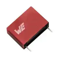
General Purpose Film Capacitor, Metallized PP, Radial Box - 2 Pin, 2.2 µF, ± 5%, 400 V
- Manufacturer: WURTH ELEKTRONIK
- Product type: General Purpose Film Capacitors
- SVHC: No SVHC (25-Jun-2025)
- Capacitance: 2.2µF
- Voltage(AC): -
- Voltage(DC): 400V
- Lead Spacing: 27.5mm
- Product Range: WCAP-FTBP Series
- Product Width: 15mm
- Qualification: -
- Product Height: 24.5mm
- Product Length: 31mm
- Dielectric Type: Metallized PP
- Humidity Rating: GRADE II (Test Condition A)
- Capacitor Mounting: Through Hole
- Capacitor Terminals: PC Pin
- Capacitance Tolerance: ± 5%
- Capacitor Case / Package: Radial Box - 2 Pin
- Operating Temperature Max: 105°C
- Operating Temperature Min: -40°C
| Delivery and price | |
|---|---|
| Units per pack | 170 |
| Price | 1.71 € |
| Current stock | 10+ |
| Lead time | 30 days |
**==> picture [799 x 517] intentionally omitted <==**

**----- Start of picture text -----**<br>
Dimensions: [mm] Recommended Hole Pattern: [mm] Electrical Properties:<br>ee Properties es Test conditions ee es Value Unit Tol.<br>Se ee Capacitance C 1 V/ 1 kHz ± 0.2 kHz 2.2 µF ±5%<br>Rated Voltage VR 400 V (DC) max.<br>[ ee es<br>Insulation Resistance RISO 1 min @ 100 V (DC) 4.55 GΩ min.<br>|na e dL| ae Dissipation Factor e e DF esGs @ 1 kHz es es 0.1 % max.<br>r —|- —_ 7 ee<br>Fs 27,5±0,5 po ee Dissipation Factor eeee DF  Gs @ 10 kHz es 0.4 % max.<br>Dissipation Factor DF @ 100 kHz 3.4 % max.<br>— — |— | — e Rate of Voltage Rise e dV/dt eeee Gsees 98 V/µs max.<br>27,5 ee Dielectric Strength Pin to Pin ee 1 min. @ 20 °C es 600 V (DC) max.<br>31,0±1,5<br>Dielectric Strength Pin toCase 5 sec. @ 20 °C 800 V (DC) max.<br>LE<br>Scale - 1:1<br>Schematic:<br>| Marking | _<br>General Information:<br>General Purpose; wound type; boxed; MKP-Metallized polypropylene<br>Operating Temperature -40 °C up to +105 °C<br>Storage Conditions<br>5 °C up to + 35 °C; 10 % rH up to 75 % rH<br>(in original packaging)<br>Maximum Selfheating (Rated) 7 °C<br>Moisture Sensitivity Level (MSL) 1<br>Climatic Category 40/105/56<br>Test conditions of electrical properties: +20 °C, 35 % rH if not specified differently<br>Scale - 1:1 FIT according to separate documentation<br>U y ==<br>CHECKED REVISION DATE (YYYY-MM-DD) GENERAL TOLERANCE PROJECTION<br>METHOD<br>FPu 002.001 2024-11-30 DIN ISO 2768-1m<br>DESCRIPTION TECHNICAL REFERENCE<br>WCAP-FTBP Film Capacitors MPPP275225J400DCPP25004<br>@ee Würth Elektronik eiSos GmbH & Co. KG fF LL de<br>EMC & Inductive Solutions ORDER CODE<br>Max-Eyth-Str. 174638 Waldenburg 890283327008CS<br>Germany<br>Tel. +49 (0) 79 42 945 - 0 SIZE/TYPE BUSINESS UNIT STATUS PAGE<br>www.we-online.com<br>eiSos@we-online.com Pitch 27.5 mm eiCap Valid 1/9<br>1,1<br>O<br>0,8±0,05<br>O<br>±1,0<br>±0,5<br>24,5<br>4,0<br>15,0±1,0<br>**----- End of picture text -----**<br>


This electronic component has been designed and developed for usage in general electronic equipment only. This product is not authorized for use in equipment where a higher safety standard and reliability standard is especially required or where a failure of the product is reasonably expected to cause severe personal injury or death, unless the parties have executed an agreement specifically governing such use. Moreover Würth Elektronik eiSos GmbH & Co KG products are neither designed nor intended for use in areas such as military, aerospace, aviation, nuclear control, submarine, transportation, transportation signal, disaster prevention, medical, public information network etc.. Würth Elektronik eiSos GmbH & Co KG must be informed about the intent of such usage before the design-in stage. In addition, sufficient reliability evaluation checks for safety must be performed on every electronic component which is used in electrical circuits that require high safety and reliability functions or performance.

## **Product Marking:**

|**Product Marking:**|||
|---|---|---|
|**1st Line right**|Matchcode: FTBP||
|**2nd Line right**|Rated Voltage: 400 V (DC)||
|**Bottom Line**|Capacitance & Tolerance Code: 225 J ( Basis pF ), Date Code ( YWW ), Internal Marking|Capacitance & Tolerance Code: 225 J ( Basis pF ), Date Code ( YWW ), Internal Marking|


## **Mechanical Properties:**

|**Properties**|Test Conditions||Lead Diameter [ mm ]|Force [ N ]|Force [ N ]|condition|
|---|---|---|---|---|---|---|
|**Termination Robustness**|IEC 60068 - 2 - 21|Pull Test|0.5 to ≤ 0.8|10||min. 10 sec.|
||||0.9 to ≤ 1.25|20||min. 10 sec.|
|||Bend Test|0.5 to ≤ 0.8|5||min. 2 cycles|
||||0.9 to ≤ 1.25|10||min. 2 cycles|


## **Test items and standards:**

|**Properties**<br>**Vibration**<br>**Damp Heat**<br>**Temperature Cycles**<br>**Certification:**<br>**RoHS Approval**<br>**REACh Approval**<br>**Halogen Free**<br>**Halogen Free**|Standard<br>IEC 60068 - 2 - 6<br>IEC 60068 - 2 - 78<br>IEC 60068 - 2 - 14|all 3 directions, 2 hours each @ 10 - 55 - 10<br>Hz, amplitude 0.75 mm or 10 g<br>40 °C, 95 % rH, 56 days<br>5 cycles, upper and lower temperature 30<br>minutes each, 3 minutes Max transfer time<br>Compliant [2011/65/EU&2015/863]<br>Conform or declared [(EC)1907/2006]<br>Conform [JEDEC JS709B]<br>Conform [IEC 61249-2-21]|
|---|---|---|


## **Certification:**

## **Capacitance Change vs. Temperature:**

|Capacitance & Tolerance Code: 225 J ( Basis pF ), Date Code ( YWW ), Internal Marking<br>Force [ N ]<br>condition<br>min. 10 sec.<br>min. 10 sec.<br>min. 2 cycles<br>min. 2 cycles<br>all 3 directions, 2 hours each @ 10 - 55 - 10<br>Hz, amplitude 0.75 mm or 10 g<br>40 °C, 95 % rH, 56 days<br>5 cycles, upper and lower temperature 30<br>minutes each, 3 minutes Max transfer time<br>Compliant [2011/65/EU&2015/863]<br>Conform or declared [(EC)1907/2006]|**Capacitance Change vs. Temperature:**<br>-5.0%<br>-3.0%<br>-1.0%<br>1.0%<br>3.0%<br>5.0%<br>-40<br>-30<br>-20<br>-10<br>0<br>10<br>20<br>30<br>40<br>50<br>60<br>70<br>80<br>90<br>100 105<br>**Capacitance Change [%]**<br>**Temperature [°C]**<br>a<br>~~a~~|**Capacitance Change vs. Temperature:**<br>-5.0%<br>-3.0%<br>-1.0%<br>1.0%<br>3.0%<br>5.0%<br>-40<br>-30<br>-20<br>-10<br>0<br>10<br>20<br>30<br>40<br>50<br>60<br>70<br>80<br>90<br>100 105<br>**Capacitance Change [%]**<br>**Temperature [°C]**<br>a<br>~~a~~|**Capacitance Change vs. Temperature:**<br>-5.0%<br>-3.0%<br>-1.0%<br>1.0%<br>3.0%<br>5.0%<br>-40<br>-30<br>-20<br>-10<br>0<br>10<br>20<br>30<br>40<br>50<br>60<br>70<br>80<br>90<br>100 105<br>**Capacitance Change [%]**<br>**Temperature [°C]**<br>a<br>~~a~~|**Capacitance Change vs. Temperature:**<br>-5.0%<br>-3.0%<br>-1.0%<br>1.0%<br>3.0%<br>5.0%<br>-40<br>-30<br>-20<br>-10<br>0<br>10<br>20<br>30<br>40<br>50<br>60<br>70<br>80<br>90<br>100 105<br>**Capacitance Change [%]**<br>**Temperature [°C]**<br>a<br>~~a~~|**Capacitance Change vs. Temperature:**<br>-5.0%<br>-3.0%<br>-1.0%<br>1.0%<br>3.0%<br>5.0%<br>-40<br>-30<br>-20<br>-10<br>0<br>10<br>20<br>30<br>40<br>50<br>60<br>70<br>80<br>90<br>100 105<br>**Capacitance Change [%]**<br>**Temperature [°C]**<br>a<br>~~a~~|**Capacitance Change vs. Temperature:**<br>-5.0%<br>-3.0%<br>-1.0%<br>1.0%<br>3.0%<br>5.0%<br>-40<br>-30<br>-20<br>-10<br>0<br>10<br>20<br>30<br>40<br>50<br>60<br>70<br>80<br>90<br>100 105<br>**Capacitance Change [%]**<br>**Temperature [°C]**<br>a<br>~~a~~|**Capacitance Change vs. Temperature:**<br>-5.0%<br>-3.0%<br>-1.0%<br>1.0%<br>3.0%<br>5.0%<br>-40<br>-30<br>-20<br>-10<br>0<br>10<br>20<br>30<br>40<br>50<br>60<br>70<br>80<br>90<br>100 105<br>**Capacitance Change [%]**<br>**Temperature [°C]**<br>a<br>~~a~~|**Capacitance Change vs. Temperature:**<br>-5.0%<br>-3.0%<br>-1.0%<br>1.0%<br>3.0%<br>5.0%<br>-40<br>-30<br>-20<br>-10<br>0<br>10<br>20<br>30<br>40<br>50<br>60<br>70<br>80<br>90<br>100 105<br>**Capacitance Change [%]**<br>**Temperature [°C]**<br>a<br>~~a~~|
|---|---|---|---|---|---|---|---|---|
|||CHECKED<br>FPu|REVISION<br>002.001|DATE (YYYY-MM-DD)<br>2024-11-30|GENERAL TOLERANCE<br>DIN ISO 2768-1m||PROJECTION<br>METHOD||
|||DESCRIPTION<br>**WCAP-FTBP Film Capacitors**||||TECHNICAL REFERENCE<br>MPPP275225J400DCPP25004|||
|Würth Elektronik eiSos GmbH & Co. KG<br>EMC & Inductive Solutions<br>Max-Eyth-Str. 1<br>74638 Waldenburg<br>Germany<br>Tel. +49 (0) 79 42 945 - 0<br>www.we-online.com<br>eiSos@we-online.com|||||||||
|||||||ORDER CODE<br>**890283327008CS**|||
|||SIZE/TYPE<br>Pitch 27.5 mm|||BUSINESS UNIT<br>eiCap|STATUS<br>Valid||PAGE<br>2/9|


This electronic component has been designed and developed for usage in general electronic equipment only. This product is not authorized for use in equipment where a higher safety standard and reliability standard is especially required or where a failure of the product is reasonably expected to cause severe personal injury or death, unless the parties have executed an agreement specifically governing such use. Moreover Würth Elektronik eiSos GmbH

- & Co KG products are neither designed nor intended for use in areas such as military, aerospace, aviation, nuclear control, submarine, transportation, transportation signal, disaster prevention, medical, public information network etc.. Würth Elektronik eiSos GmbH & Co KG must be informed about the intent of such usage before the design-in stage. In addition, sufficient reliability evaluation checks for safety must be performed on every electronic component which is used in electrical circuits that require high safety and reliability functions or performance.

## **Dissipation Factor vs. Temperature:**

## **Rated Voltage vs. Temperature:**

**==> picture [795 x 516] intentionally omitted <==**

**----- Start of picture text -----**<br>
0.100% 120.0%<br>PT TT ETE ETE EE EEE EEE PT TTT tT iyi te et ey ey ey ee<br>PLETE EEE EE EEE ELE LEP EP EEE Pit itt TT tT TT TT Py ty [TT]<br>POEL PEELE AER EEREEEEEEE<br>PLETE EEE EE EEE ELE LEP EP EEE See eee<br>100.0%<br>0.080%<br>SSE EE<br>PLETE EEE EE EEE ELE LEP EP EEE Pit itt TT tT TT TT Py ty [TT]<br>SES0 000000 00000000 Gee eeeeeeee EERE EEE EEE EEEEEE EEE EEE EEE EE<br>80.0%<br>Pie ETE ELE EEE EEL EEL EEE LEE EE FP}PTT tt PEEett P ee teeLetT TT ELLE ET E EEL L E TLLLLELLELLLEE EE EE<br>0.060%<br>SeesPLE EEEpeseta EE EE eesEEE ELEereeeaEEE? eesEP ETEtienes LEE a TTTPit itt TT tTTI TT TT PyTTty [TT]<br>60.0%<br>SES0 000000 00000000 Gee eeeeeeee PEE CECE EEEEEE<br>Pie ETE ELE EEE EEL EEL EEE LEE EE P i}y ttPee eet ee EE E E EELE E EELE EE E EL E ELL E LELLE<br>0.040%<br>HERE EH a eeee<br>POPE) Lee TES 40.0% Pitt tT tT eT PPP<br>rT ar LES Pi ti yt tte TT TE TT Py Ee EE<br>|_| a P} tt et tee EE EE EE EE EE EE EE<br>PTT tLe EEE EEE EE Py Pee EE EELEEELEELELLELELL<br>0.020%<br>FEE EEE EEE 20.0% PEEEEEEEEEEEEEEEEEEEEEEEEE<br>PEPE EE EE EE EEE EEE EE EE EEE Pit i PITT TTT tT tT TP Pe eye eeEEtt<br>REUOAUOMEBTOGUGBUOGUOREEEGIE Saceennanceennn<br>0.000% PiePLETEEE EEL EEE  EEL EEL EE EEL EEE EEL Ey Ey  EL  EEE EEE EE 0.0% PT PEP  PPPPePeeeeePEPE EEE EEE E LELELL<br>-40 -30 -20 -10 0 10 20 30 40 50 60 70 80 90 100 105 -40 -30 -20 -10 0 10 20 30 40 50 60 70 80 90 100 105<br>Temperature [°C] Temperature [°C]<br>CHECKED REVISION DATE (YYYY-MM-DD) GENERAL TOLERANCE PROJECTION<br>METHOD<br>FPu 002.001 2024-11-30 DIN ISO 2768-1m<br>| DESCRIPTION | ft TECHNICAL REFERENCE | eo<br>WCAP-FTBP Film Capacitors MPPP275225J400DCPP25004<br>Würth Elektronik eiSos GmbH & Co. KG<br>EMC & Inductive Solutions ORDER CODE<br>Max-Eyth-Str. 174638 Waldenburg 890283327008CS<br>Germany<br>WE = [Brose] Tel. +49 (0) 79 42 945 - 0www.we-online.com Oo SIZE/TYPE BUSINESS UNIT STATUS PAGE<br>eiSos@we-online.com Pitch 27.5 mm eiCap Valid 3/9<br>ae ee<br>This electronic component has been designed and developed for usage in general electronic equipment only. This product is not authorized for use in equipment where a higher safety standard and reliability standard is especially required or where a failure of the product is reasonably expected to cause severe personal injury or death, unless the parties have executed an agreement specifically governing such use. Moreover Würth Elektronik eiSos GmbH ee<br>Dissipation Factor [%] Rated Voltage / Max Voltage [%]<br>**----- End of picture text -----**<br>


This electronic component has been designed and developed for usage in general electronic equipment only. This product is not authorized for use in equipment where a higher safety standard and reliability standard is especially required or where a failure of the product is reasonably expected to cause severe personal injury or death, unless the parties have executed an agreement specifically governing such use. Moreover Würth Elektronik eiSos GmbH & Co KG products are neither designed nor intended for use in areas such as military, aerospace, aviation, nuclear control, submarine, transportation, transportation signal, disaster prevention, medical, public information network etc.. Würth Elektronik eiSos GmbH & Co KG must be informed about the intent of such usage before the design-in stage. In addition, sufficient reliability evaluation checks for safety must be performed on every electronic component which is used in electrical circuits that require high safety and reliability functions or performance.

**==> picture [216 x 12] intentionally omitted <==**

**----- Start of picture text -----**<br>
Packaging Specification - Inner Carton: [mm]<br>**----- End of picture text -----**<br>


**==> picture [218 x 12] intentionally omitted <==**

**----- Start of picture text -----**<br>
Packaging Specification - Outer Carton: [mm]<br>**----- End of picture text -----**<br>


**==> picture [778 x 458] intentionally omitted <==**

**----- Start of picture text -----**<br>
Paperboard sa asesatasasts tte.<br>Se Ni \iisissassee n tsssasesatestactaesesesateae?<br>in ieee<br>CAAyy, e sesarey)ees A ><br>Y> Wt R yyy a ‘a e yyy P yy y taeALe Bry ,PIiet Ch e e AL a un CAi T L al ra Ra a veee Wll yteee l ythu Lis  meee s e eeeSeergigeie \<br>Cet yy,<br>lh Te Tee Tee tee<br>atesP S. D e . Dee Dee tee tee h<br>eSTee aaaPeT ee Te s te, c Dt e et ee Tee tet Te e n tet treetecttes hy teeheeaPe), ,<br>Ch e e Tee teeth aaa =<br>aaaaa D y re} RPr e h hTee . teethtatseh han eh atwets h y be s<br>gtaeePeaeaaTeetetteetee te et h e e ee5.TeeteeT e eteet T e etre e teeteee hB ee Dehh et Deat<ah vrsb a hst te s<br>egypeeee~~TeeTeeTeeP e Teee et hTee t Teeh Teer e Tee t h traa e e ee e e teeaaahtee ethtr e eehh h y P s beBaty s bes<br>TS t aaa tata er D s<br>RPeeTee DeeDA t e Treete et h Deh ee t e teeeth t e seetee h y vhsir s<br>ReeeegTet TeeDee teee t tetee teeheh atehThsThs<br>RDeegPee TeeDeteTee ~ De at teh e nay} nat<br>Tee re te tee eIPS<br>RR Tee IP s<br>Rs Naw Test ee<br>LIC (mm) WIC (mm) HIC (mm) No. ofPaperboard No. ofLayer PackagingUnit Material LC (mm) WC (mm) HC (mm) No. ofinner Carton PackagingUnit Material<br>Tolerance typ. typ. typ. pcs. pcs. pcs. Tolerance typ. typ. typ. pcs. pcs.<br>Value 275,00 160,00 95,00 3 2 170 Paper Value 500,00 290,00 240,00 6 1020 Paper<br>a po<br>CHECKED REVISION DATE (YYYY-MM-DD) GENERAL TOLERANCE PROJECTION i]<br>METHOD<br>FPu 002.001 2024-11-30 DIN ISO 2768-1m<br>DESCRIPTION TECHNICAL REFERENCE<br>WCAP-FTBP Film Capacitors MPPP275225J400DCPP25004<br>~ — Würth Elektronik eiSos GmbH & Co. KG So<br>EMC & Inductive Solutions ORDER CODE<br>ELEKTRONIK Max-Eyth-Str. 174638 Waldenburg74638 Waldenburg 890283327008CS<br>FLEKTRMORE THAN GermanyTel. +49 (0) 79 42 945 - 0Tel. +49 (0) 79 42 945 - 0 SIZE/TYPE BUSINESS UNIT FS STATUS PAGE<br>YOU EXPECT www.we-online.com<br>Pitch 27.5 mm eiCap Valid 4/9<br>L C<br>W<br>C<br>L IC<br>W<br>IC<br>IC<br>H<br>C<br>H<br>**----- End of picture text -----**<br>


Würth Elektronik eiSos GmbH & Co. KG EMC & Inductive Solutions Max-Eyth-Str. 174638 Waldenburg74638 Waldenburg GermanyTel. +49 (0) 79 42 945 - 0Tel. +49 (0) 79 42 945 - 0 www.we-online.com eiSos@we-online.com

This electronic component has been designed and developed for usage in general electronic equipment only. This product is not authorized for use in equipment where a higher safety standard and reliability standard is especially required or where a failure of the product is reasonably expected to cause severe personal injury or death, unless the parties have executed an agreement specifically governing such use. Moreover Würth Elektronik eiSos GmbH & Co KG products are neither designed nor intended for use in areas such as military, aerospace, aviation, nuclear control, submarine, transportation, transportation signal, disaster prevention, medical, public information network etc.. Würth Elektronik eiSos GmbH & Co KG must be informed about the intent of such usage before the design-in stage. In addition, sufficient reliability evaluation checks for safety must be performed on every electronic component which is used in electrical circuits that require high safety and reliability functions or performance.

## **Classification Wave Soldering Profile:**

**==> picture [234 x 204] intentionally omitted <==**

**----- Start of picture text -----**<br>
t<br>p<br>T<br>p<br>First Wave Second Wave<br>\.<br>‘.\<br>\,<br>\1\<br>11s.<br>\<br>VS<br>es<br>1 .<br>.<br>Ts max ag ‘ . _<br>T<br>s typical e ' .Y .<br>Ts min Pag ° Poa . . ss.<br>oe Pad _<br>oe ° . * .<br>of Preheat area Cool down area me<br>**----- End of picture text -----**<br>


**==> picture [11 x 58] intentionally omitted <==**

**----- Start of picture text -----**<br>
Temperature<br>**----- End of picture text -----**<br>


## **Time**

typical temperature procedure min temperature procedure max temperature procedure

## **Classification Wave Soldering Profile:**

|aro<br>Tee<br>eee|**Classification Wave Soldering Profile:**<br>**Profile Feature**<br>**Pb-Free Assembly**<br>**Sn-Pb Assembly**<br>**Preheat Temperature Min**<br>Ts min<br>100 °C<br>100 °C<br>**Preheat Temperature Typical**<br>Ts typical<br>120 °C<br>120 °C<br>**Preheat Temperature Max**<br>Ts max<br>130 °C<br>130 °C<br>**Preheat Time ts from Ts min to Ts max**<br>ts<br>70 seconds<br>70 seconds<br>**Ramp-up Rate Δ Temperature from Ts typical**<br>**to Tp**<br>Δ T<br>150 °C max.<br>150 °C max.<br>**Peak Temperature**<br>Tp<br>250 °C - 260 °C<br>235 °C - 260 °C<br>**Time of actual peak temperature**<br>tp<br>max. 10 seconds<br>max. 5 seconds each wave<br>max. 10 seconds<br>max. 5 seconds each wave<br>**Ramp-down Rate, Min**<br>~ 2 K/ second<br>~ 2 K/ second<br>**Ramp-down Rate, Typical**<br>~ 3.5 K/ second<br>~ 3.5 K/ second<br>**Ramp-down Rate, Max**<br>~ 5 K/ second<br>~ 5 K/ second<br>**Time 25 °C to 25 °C**<br>4 minutes<br>4 minutes<br>refer to EN61760-1:2006<br>~~a~~<br>~~a~~<br>~~(~~|**Classification Wave Soldering Profile:**<br>**Profile Feature**<br>**Pb-Free Assembly**<br>**Sn-Pb Assembly**<br>**Preheat Temperature Min**<br>Ts min<br>100 °C<br>100 °C<br>**Preheat Temperature Typical**<br>Ts typical<br>120 °C<br>120 °C<br>**Preheat Temperature Max**<br>Ts max<br>130 °C<br>130 °C<br>**Preheat Time ts from Ts min to Ts max**<br>ts<br>70 seconds<br>70 seconds<br>**Ramp-up Rate Δ Temperature from Ts typical**<br>**to Tp**<br>Δ T<br>150 °C max.<br>150 °C max.<br>**Peak Temperature**<br>Tp<br>250 °C - 260 °C<br>235 °C - 260 °C<br>**Time of actual peak temperature**<br>tp<br>max. 10 seconds<br>max. 5 seconds each wave<br>max. 10 seconds<br>max. 5 seconds each wave<br>**Ramp-down Rate, Min**<br>~ 2 K/ second<br>~ 2 K/ second<br>**Ramp-down Rate, Typical**<br>~ 3.5 K/ second<br>~ 3.5 K/ second<br>**Ramp-down Rate, Max**<br>~ 5 K/ second<br>~ 5 K/ second<br>**Time 25 °C to 25 °C**<br>4 minutes<br>4 minutes<br>refer to EN61760-1:2006<br>~~a~~<br>~~a~~<br>~~(~~|**Classification Wave Soldering Profile:**<br>**Profile Feature**<br>**Pb-Free Assembly**<br>**Sn-Pb Assembly**<br>**Preheat Temperature Min**<br>Ts min<br>100 °C<br>100 °C<br>**Preheat Temperature Typical**<br>Ts typical<br>120 °C<br>120 °C<br>**Preheat Temperature Max**<br>Ts max<br>130 °C<br>130 °C<br>**Preheat Time ts from Ts min to Ts max**<br>ts<br>70 seconds<br>70 seconds<br>**Ramp-up Rate Δ Temperature from Ts typical**<br>**to Tp**<br>Δ T<br>150 °C max.<br>150 °C max.<br>**Peak Temperature**<br>Tp<br>250 °C - 260 °C<br>235 °C - 260 °C<br>**Time of actual peak temperature**<br>tp<br>max. 10 seconds<br>max. 5 seconds each wave<br>max. 10 seconds<br>max. 5 seconds each wave<br>**Ramp-down Rate, Min**<br>~ 2 K/ second<br>~ 2 K/ second<br>**Ramp-down Rate, Typical**<br>~ 3.5 K/ second<br>~ 3.5 K/ second<br>**Ramp-down Rate, Max**<br>~ 5 K/ second<br>~ 5 K/ second<br>**Time 25 °C to 25 °C**<br>4 minutes<br>4 minutes<br>refer to EN61760-1:2006<br>~~a~~<br>~~a~~<br>~~(~~|**Classification Wave Soldering Profile:**<br>**Profile Feature**<br>**Pb-Free Assembly**<br>**Sn-Pb Assembly**<br>**Preheat Temperature Min**<br>Ts min<br>100 °C<br>100 °C<br>**Preheat Temperature Typical**<br>Ts typical<br>120 °C<br>120 °C<br>**Preheat Temperature Max**<br>Ts max<br>130 °C<br>130 °C<br>**Preheat Time ts from Ts min to Ts max**<br>ts<br>70 seconds<br>70 seconds<br>**Ramp-up Rate Δ Temperature from Ts typical**<br>**to Tp**<br>Δ T<br>150 °C max.<br>150 °C max.<br>**Peak Temperature**<br>Tp<br>250 °C - 260 °C<br>235 °C - 260 °C<br>**Time of actual peak temperature**<br>tp<br>max. 10 seconds<br>max. 5 seconds each wave<br>max. 10 seconds<br>max. 5 seconds each wave<br>**Ramp-down Rate, Min**<br>~ 2 K/ second<br>~ 2 K/ second<br>**Ramp-down Rate, Typical**<br>~ 3.5 K/ second<br>~ 3.5 K/ second<br>**Ramp-down Rate, Max**<br>~ 5 K/ second<br>~ 5 K/ second<br>**Time 25 °C to 25 °C**<br>4 minutes<br>4 minutes<br>refer to EN61760-1:2006<br>~~a~~<br>~~a~~<br>~~(~~|**Classification Wave Soldering Profile:**<br>**Profile Feature**<br>**Pb-Free Assembly**<br>**Sn-Pb Assembly**<br>**Preheat Temperature Min**<br>Ts min<br>100 °C<br>100 °C<br>**Preheat Temperature Typical**<br>Ts typical<br>120 °C<br>120 °C<br>**Preheat Temperature Max**<br>Ts max<br>130 °C<br>130 °C<br>**Preheat Time ts from Ts min to Ts max**<br>ts<br>70 seconds<br>70 seconds<br>**Ramp-up Rate Δ Temperature from Ts typical**<br>**to Tp**<br>Δ T<br>150 °C max.<br>150 °C max.<br>**Peak Temperature**<br>Tp<br>250 °C - 260 °C<br>235 °C - 260 °C<br>**Time of actual peak temperature**<br>tp<br>max. 10 seconds<br>max. 5 seconds each wave<br>max. 10 seconds<br>max. 5 seconds each wave<br>**Ramp-down Rate, Min**<br>~ 2 K/ second<br>~ 2 K/ second<br>**Ramp-down Rate, Typical**<br>~ 3.5 K/ second<br>~ 3.5 K/ second<br>**Ramp-down Rate, Max**<br>~ 5 K/ second<br>~ 5 K/ second<br>**Time 25 °C to 25 °C**<br>4 minutes<br>4 minutes<br>refer to EN61760-1:2006<br>~~a~~<br>~~a~~<br>~~(~~|**Classification Wave Soldering Profile:**<br>**Profile Feature**<br>**Pb-Free Assembly**<br>**Sn-Pb Assembly**<br>**Preheat Temperature Min**<br>Ts min<br>100 °C<br>100 °C<br>**Preheat Temperature Typical**<br>Ts typical<br>120 °C<br>120 °C<br>**Preheat Temperature Max**<br>Ts max<br>130 °C<br>130 °C<br>**Preheat Time ts from Ts min to Ts max**<br>ts<br>70 seconds<br>70 seconds<br>**Ramp-up Rate Δ Temperature from Ts typical**<br>**to Tp**<br>Δ T<br>150 °C max.<br>150 °C max.<br>**Peak Temperature**<br>Tp<br>250 °C - 260 °C<br>235 °C - 260 °C<br>**Time of actual peak temperature**<br>tp<br>max. 10 seconds<br>max. 5 seconds each wave<br>max. 10 seconds<br>max. 5 seconds each wave<br>**Ramp-down Rate, Min**<br>~ 2 K/ second<br>~ 2 K/ second<br>**Ramp-down Rate, Typical**<br>~ 3.5 K/ second<br>~ 3.5 K/ second<br>**Ramp-down Rate, Max**<br>~ 5 K/ second<br>~ 5 K/ second<br>**Time 25 °C to 25 °C**<br>4 minutes<br>4 minutes<br>refer to EN61760-1:2006<br>~~a~~<br>~~a~~<br>~~(~~|**Classification Wave Soldering Profile:**<br>**Profile Feature**<br>**Pb-Free Assembly**<br>**Sn-Pb Assembly**<br>**Preheat Temperature Min**<br>Ts min<br>100 °C<br>100 °C<br>**Preheat Temperature Typical**<br>Ts typical<br>120 °C<br>120 °C<br>**Preheat Temperature Max**<br>Ts max<br>130 °C<br>130 °C<br>**Preheat Time ts from Ts min to Ts max**<br>ts<br>70 seconds<br>70 seconds<br>**Ramp-up Rate Δ Temperature from Ts typical**<br>**to Tp**<br>Δ T<br>150 °C max.<br>150 °C max.<br>**Peak Temperature**<br>Tp<br>250 °C - 260 °C<br>235 °C - 260 °C<br>**Time of actual peak temperature**<br>tp<br>max. 10 seconds<br>max. 5 seconds each wave<br>max. 10 seconds<br>max. 5 seconds each wave<br>**Ramp-down Rate, Min**<br>~ 2 K/ second<br>~ 2 K/ second<br>**Ramp-down Rate, Typical**<br>~ 3.5 K/ second<br>~ 3.5 K/ second<br>**Ramp-down Rate, Max**<br>~ 5 K/ second<br>~ 5 K/ second<br>**Time 25 °C to 25 °C**<br>4 minutes<br>4 minutes<br>refer to EN61760-1:2006<br>~~a~~<br>~~a~~<br>~~(~~|**Classification Wave Soldering Profile:**<br>**Profile Feature**<br>**Pb-Free Assembly**<br>**Sn-Pb Assembly**<br>**Preheat Temperature Min**<br>Ts min<br>100 °C<br>100 °C<br>**Preheat Temperature Typical**<br>Ts typical<br>120 °C<br>120 °C<br>**Preheat Temperature Max**<br>Ts max<br>130 °C<br>130 °C<br>**Preheat Time ts from Ts min to Ts max**<br>ts<br>70 seconds<br>70 seconds<br>**Ramp-up Rate Δ Temperature from Ts typical**<br>**to Tp**<br>Δ T<br>150 °C max.<br>150 °C max.<br>**Peak Temperature**<br>Tp<br>250 °C - 260 °C<br>235 °C - 260 °C<br>**Time of actual peak temperature**<br>tp<br>max. 10 seconds<br>max. 5 seconds each wave<br>max. 10 seconds<br>max. 5 seconds each wave<br>**Ramp-down Rate, Min**<br>~ 2 K/ second<br>~ 2 K/ second<br>**Ramp-down Rate, Typical**<br>~ 3.5 K/ second<br>~ 3.5 K/ second<br>**Ramp-down Rate, Max**<br>~ 5 K/ second<br>~ 5 K/ second<br>**Time 25 °C to 25 °C**<br>4 minutes<br>4 minutes<br>refer to EN61760-1:2006<br>~~a~~<br>~~a~~<br>~~(~~|
|---|---|---|---|---|---|---|---|---|
|&<br>6||CHECKED<br>FPu|REVISION<br>002.001|DATE (YYYY-MM-DD)<br>2024-11-30|GENERAL TOLERANCE<br>DIN ISO 2768-1m||PROJECTION<br>METHOD<br>i]<br>3||
|||DESCRIPTION<br>**WCAP-FTBP Film Capacitors**||||TECHNICAL REFERENCE<br>MPPP275225J400DCPP25004|||
|Würth Elektronik eiSos GmbH & Co. KG<br>EMC & Inductive Solutions<br>Max-Eyth-Str. 1<br>74638 Waldenburg<br>Germany<br>Tel. +49 (0) 79 42 945 - 0<br>www.we-online.com<br>eiSos@we-online.com<br>\WURTH<br>W/E<br>ELEKTRONIK<br>MORE<br>THAN<br>YOU EXPECT|||||||||
|||||||ORDER CODE<br>**890283327008CS**|||
|||SIZE/TYPE<br>Pitch 27.5 mm|||BUSINESS UNIT<br>eiCap|STATUS<br>Valid||PAGE<br>5/9|


This electronic component has been designed and developed for usage in general electronic equipment only. This product is not authorized for use in equipment where a higher safety standard and reliability standard is especially required or where a failure of the product is reasonably expected to cause severe personal injury or death, unless the parties have executed an agreement specifically governing such use. Moreover Würth Elektronik eiSos GmbH

& Co KG products are neither designed nor intended for use in areas such as military, aerospace, aviation, nuclear control, submarine, transportation, transportation signal, disaster prevention, medical, public information network etc.. Würth Elektronik eiSos GmbH & Co KG must be informed about the intent of such usage before the design-in stage. In addition, sufficient reliability evaluation checks for safety must be performed on every electronic component which is used in electrical circuits that require high safety and reliability functions or performance.

## **Further information**

## **Tutorials:**

|**Further information**|**Further information**||
|---|---|---|
|**Component Libraries:**|||
||3D_890283327008CS||
||Altium_WCAP-FTBP(22c)||
||Downloads_CADENCE_WCAP-FTBP|AP-FTBP(22a)|
||Cadstar_WCAP-FTBP(19a)||
||Eagle_WCAP-FTBP(20a)||
||IGS_890283327008CS||
||PSpice_WCAP-FTBP(24a)||
||Download_STP_890283327008CS||
|**Design Kits:**|||
|■<br>Design KitWCAP-FTBPGeneral Purpose|||
||||
|**Free Sample Order:**|||
|Order free samples ofthis article directlyhere!|||


|■<br>Capacitor PortfolioFlyer(PDF)|
|---|
||
|**REDEXPERT:**|
|Determine characteristicsfor890283327008CSwith REDEXPERT|


||CHECKED|REVISION||DATE (YYYY-MM-DD)|GENERAL TOLERANCE||PROJECTION||
|---|---|---|---|---|---|---|---|---|
||||||||METHOD||
||FPu|002.001||2024-11-30|DIN ISO 2768-1m||||
||DESCRIPTION|||||TECHNICAL REFERENCE|||
||**WCAP-FTBP Film Capacitors**||**WCAP-FTBP Film Capacitors**|||MPPP275225J400DCPP25004|||
|Würth Elektronik eiSos GmbH & Co. KG|||||||||
|EMC & Inductive Solutions||||||ORDER CODE|||
|Max-Eyth-Str. 1<br>74638 Waldenburg||||||**890283327008CS**|||
|Germany|||||||||
|Tel. +49 (0) 79 42 945 - 0|SIZE/TYPE||||BUSINESS UNIT|STATUS||PAGE|
|www.we-online.com<br>eiSos@we-online.com|Pitch 27.5 mm||||eiCap|Valid||6/9|


This electronic component has been designed and developed for usage in general electronic equipment only. This product is not authorized for use in equipment where a higher safety standard and reliability standard is especially required or where a failure of the product is reasonably expected to cause severe personal injury or death, unless the parties have executed an agreement specifically governing such use. Moreover Würth Elektronik eiSos GmbH

- & Co KG products are neither designed nor intended for use in areas such as military, aerospace, aviation, nuclear control, submarine, transportation, transportation signal, disaster prevention, medical, public information network etc.. Würth Elektronik eiSos GmbH & Co KG must be informed about the intent of such usage before the design-in stage. In addition, sufficient reliability evaluation checks for safety must be performed on every electronic component which is used in electrical circuits that require high safety and reliability functions or performance.

## **Cautions and Warnings:**

## **The following conditions apply to all goods within the product series of Film Capacitors of Würth Elektronik eiSos GmbH & Co. KG:**

## **General:**

- The storage conditions stated in the original packaging apply to the storage time and not to the transportation time of the components.

## **Operating climatic conditions:**

   - Do not exceed the lower nor the upper specified temperature under no circumstances.

   - Do not use the capacitors under high humidity, high temperature or under high or low atmospheric pressure which may affect capacitors reliability.

   - Surface temperature including self-heating must be kept below the maximum operating temperature.

- This electronic component is designed and manufactured for use in general electronic equipment.

- Würth Elektronik must be asked for a written approval (following the certain PPAP level procedure) before incorporating the components into any equipment in the field such as military, aerospace, aviation, nuclear control, submarine, transportation (automotive control, train control, ship control), transportation signal, disaster prevention, medical, public information network etc. where higher safety and reliability are especially required and/or if there is the possibility of direct damage or human injury.

- Electronic components that will be used in safety-critical or high-reliability applications, should be pre-evaluated by the customer.

- Direct mechanical impact to the product shall be prevented as material of the body, pins or termination could flake or in the worst case it could break.

- Avoid any water or heavy dust on capacitors surface, which may cause electrical leakage, damage, overheating or corrosion.

- Würth Elektronik products are qualified according to international standards, which are listed in each product reliability report. Würth Elektronik does not warrant any customer qualified product characteristic, beyond Würth Elektronik specifications, for its validity and sustainability over time.

- The customer is responsible for the functionality of his or her own products. All technical specifications for standard products also apply to customer specific products.

- The component is designed and manufactured to be used within the datasheet specified values. If the usage and operation conditions specified in the datasheet are not met, the body, pins or termination may be damaged or dissolved.

## **Operating load conditions:**

   - Due to self-heating the reliability of the capacitor may be reduced, if high frequency AC or pulse is applied.

   - Consider carefully possible specific changes of electrical characteristics like capacitance over temperature, voltage and time as well as the specific performance over frequency for the actual use conditions.

   - Avoid any overvoltage and do not apply a continuous overvoltage. If an overvoltage is applied to the capacitor, the leakage current can increase drastically. The applied working voltage is not allowed to exceed the rated working voltage of the specific capacitor.

   - If film capacitors with safety approvals are operated with a DC voltage exceeding the specified AC voltage, the approvals given on the basis of IEC 60384-14 are no longer valid.

   - For the WCAP-FTDB film capacitor the maximum peak voltage Vpeak+ shall not be greater than the rated voltage VR according to the temperature derating of the rated voltage VR. The peak-to-peak value of the ripple voltage Vp-p should not be greater than 0.3*VR according to the temperature derating of the rated voltage VR. The rated voltage of the capacitor may need to be reduced for different operating temperatures. See voltage derating curve within this datasheet.

   - Film capacitors from Würth Elektronik are generally not designed for series connection to the mains and are not suitable for this application, unless otherwise specified.

- Do not apply any kind of flexural or compressive force onto soldered or unsoldered component.

- The capacitance tolerance as specified within the datasheet is only valid on the date of delivery and according specified measurement criteria.

## **Product specific:**

## **Storage conditions:**

- A storage of Würth Elektronik products for longer than 12 months is not recommended. Within other effects, the terminals may suffer degradation, resulting in bad solderability. Therefore, all products shall be used within the period of 12 months based on the day of shipment.

- Do not expose the components into direct sunlight.

- The storage condition in the original packaging is defined according to DIN EN 61760-2.

- The environment in which the capacitors are operated and stored has to have atmospheric characteristics and must be free of dew condensation and toxic gases (e.g. chlorine, ammonia, sulfur, hydrogen sulphide and hydrogen sulfate).

- Do not expose the capacitor to environments with hazardous gas, ozone, ultraviolet rays or any kind of radiation. Avoid any contact of the capacitor with direct sunshine, saltwater, spray of water or types of oil during storage.

The following information describes the effect of humidity on capacitance stability:

- Prolonged exposure of film capacitors to humid environments can lead to irreversible consequences. Direct interaction with liquid water or excessive exposure to high ambient humidity or dew can eventually erode the film metallization, resulting in capacitor failure. It is crucial to precisely test plastic boxed capacitors under the most extreme anticipated conditions of temperature and humidity in their final application to ensure that any parameter drift does not cause circuit malfunction. If humidity infiltrates the film, the metal layer may deteriorate, particularly under AC operation (polarity changes), which is exacerbated by elevated temperatures. This degradation can increase the series resistance of the electrode and decrease the capacitance value. For DC operation, the parameter drift is significantly less pronounced. Plastic enclosures and resins do not provide complete protection against humidity. Additional protective measures, implemented by customers in their applications, can offer enhanced defense against humidity ingress.

## **Packaging:**

- The packaging specifications apply only to purchase orders comprising whole packaging units. If the ordered quantity exceeds or is lower than the specified packaging unit, packaging in accordance with the packaging specifications cannot be ensured.

|6}|CHECKED<br>FPu<br>~~i~~|REVISION<br>002.001<br>~~|~~|DATE (YYYY-MM-DD)<br>2024-11-30<br>~~|~~|GENERAL TOLERANCE<br>DIN ISO 2768-1m<br>~~|~~|GENERAL TOLERANCE<br>DIN ISO 2768-1m<br>~~|~~|PROJECTION<br>METHOD<br>~~ae]~~|PROJECTION<br>METHOD<br>~~ae]~~|
|---|---|---|---|---|---|---|---|
||DESCRIPTION<br>**WCAP-FTBP Film Capacitors**<br>~~i~~<br>~~|~~<br>~~|~~||||TECHNICAL REFERENCE<br>MPPP275225J400DCPP25004<br>~~|~~<br>~~ae]~~|||
|Würth Elektronik eiSos GmbH & Co. KG<br>EMC & Inductive Solutions<br>Max-Eyth-Str. 1<br>74638 Waldenburg<br>Germany<br>Tel. +49 (0) 79 42 945 - 0<br>www.we-online.com<br>eiSos@we-online.com<br>ELEKTRONIK<br>MORE THAN||||||||
||||||ORDER CODE<br>**890283327008CS**|||
||SIZE/TYPE<br>Pitch 27.5 mm|||BUSINESS UNIT<br>eiCap|STATUS<br>Valid||PAGE<br>7/9|


This electronic component has been designed and developed for usage in general electronic equipment only. This product is not authorized for use in equipment where a higher safety standard and reliability standard is especially required or where a failure of the product is reasonably expected to cause severe personal injury or death, unless the parties have executed an agreement specifically governing such use. Moreover Würth Elektronik eiSos GmbH

& Co KG products are neither designed nor intended for use in areas such as military, aerospace, aviation, nuclear control, submarine, transportation, transportation signal, disaster prevention, medical, public information network etc.. Würth Elektronik eiSos GmbH & Co KG must be informed about the intent of such usage before the design-in stage. In addition, sufficient reliability evaluation checks for safety must be performed on every electronic component which is used in electrical circuits that require high safety and reliability functions or performance.

## **Soldering:**

- The solder profile must comply with the technical product specifications. All other profiles will void the warranty.

## **Flammability:**

   - Avoid any external energy or open fire (passive flammability).

- All other soldering methods are at the customer’s own risk.

- Strong forces which may affect the coplanarity of the component’s electrical connection with the PCB (i.e. pins), can damage the part, resulting in void of the warranty.

These cautions and warnings comply with the state of the scientific and technical knowledge and are believed to be accurate and reliable. However, no responsibility is assumed for inaccuracies or incompleteness.(V2.4)

- Customer needs to ensure that the applied solder paste, the paste thickness and solder conditions are enough to guarantee a sufficient solder result according to the relevant criteria of IPC-A-610.

- Excessive amount of solder may lead to higher tensile force and chip cracking. Insufficient amount of solder may detach the capacitor due to defective contacts.

- Do not use excessive nor insufficient flux.

## **Cleaning:**

- Do not use any other cleaning solvents for box-typed capacitors except: ethanol, isopropanol, n-propanol - water mixtures.

- After cleaning a drying process with temperatures not exceeding 65°C and not longer than 4 hours is mandatory to prevent any kind of electrical damage.

## **Coating, molding and potting of the PCB:**

- If the product is potted in the costumer’s application, the potting material might shrink or expand during and after hardening. Shrinking could lead to an incomplete seal, allowing contaminants into the body and termination. Expansion could damage the body or termination. We recommend a manual inspection after potting to avoid these effects.

- If final assemblies will be placed completely in any plastic resin, physical, chemical and thermal influences must be considered.

- When coating and molding the PCB, verify the quality influence on the capacitor.

- Verify the curing temperature and assure that there is no harmful decomposing or reaction gas emission during curing.

- Do not exceed the specified max. self-heating.

## **Vibration resistance:**

- Do not exceed the vibration limits given by IEC60068-2-6.

## **Handling:**

- After soldering, please pay attention not to bend, twist or distort the PCB in handling and storage.

- Avoid excessive pressure during the functional check of the PCB.

- Avoid bending stress while breaking the PCB.

- WCAP-FTXX and WCAP-FTX2 capacitors are not designed and not recommended to be used in series connection to the mains.

- The temperature rise of the component must be taken into consideration. The operating temperature is comprised of ambient temperature and temperature rise of the component.The operating temperature of the component shall not exceed the maximum temperature specified.

|6}|CHECKED<br>FPu<br>~~i~~|REVISION<br>002.001<br>~~|~~|DATE (YYYY-MM-DD)<br>2024-11-30<br>~~|~~|GENERAL TOLERANCE<br>DIN ISO 2768-1m<br>~~|~~|GENERAL TOLERANCE<br>DIN ISO 2768-1m<br>~~|~~|PROJECTION<br>METHOD<br>~~ae]~~|PROJECTION<br>METHOD<br>~~ae]~~|
|---|---|---|---|---|---|---|---|
||DESCRIPTION<br>**WCAP-FTBP Film Capacitors**<br>~~i~~<br>~~|~~<br>~~|~~||||TECHNICAL REFERENCE<br>MPPP275225J400DCPP25004<br>~~|~~<br>~~ae]~~|||
|Würth Elektronik eiSos GmbH & Co. KG<br>EMC & Inductive Solutions<br>Max-Eyth-Str. 1<br>74638 Waldenburg<br>Germany<br>Tel. +49 (0) 79 42 945 - 0<br>www.we-online.com<br>eiSos@we-online.com<br>ELEKTRONIK<br>MORE THAN||||||||
||||||ORDER CODE<br>**890283327008CS**|||
||SIZE/TYPE<br>Pitch 27.5 mm|||BUSINESS UNIT<br>eiCap|STATUS<br>Valid||PAGE<br>8/9|


This electronic component has been designed and developed for usage in general electronic equipment only. This product is not authorized for use in equipment where a higher safety standard and reliability standard is especially required or where a failure of the product is reasonably expected to cause severe personal injury or death, unless the parties have executed an agreement specifically governing such use. Moreover Würth Elektronik eiSos GmbH & Co KG products are neither designed nor intended for use in areas such as military, aerospace, aviation, nuclear control, submarine, transportation, transportation signal, disaster prevention, medical, public information network etc.. Würth Elektronik eiSos GmbH & Co KG must be informed about the intent of such usage before the design-in stage. In addition, sufficient reliability evaluation checks for safety must be performed on every electronic component which is used in electrical circuits that require high safety and reliability functions or performance.

## **Important Notes**

## **The following conditions apply to all goods within the product range of Würth Elektronik eiSos GmbH & Co. KG:**

## **1. General Customer Responsibility**

Some goods within the product range of Würth Elektronik eiSos GmbH & Co. KG contain statements regarding general suitability for certain application areas. These statements about suitability are based on our knowledge and experience of typical requirements concerning the areas, serve as general guidance and cannot be estimated as binding statements about the suitability for a customer application. The responsibility for the applicability and use in a particular customer design is always solely within the authority of the customer. Due to this fact it is up to the customer to evaluate, where appropriate to investigate and decide whether the device with the specific product characteristics described in the product specification is valid and suitable for the respective customer application or not.

## **2. Customer Responsibility related to Specific, in particular Safety-Relevant Applications**

## **6. Product Life Cycle**

Due to technical progress and economical evaluation we also reserve the right to discontinue production and delivery of products. As a standard reporting procedure of the Product Termination Notification (PTN) according to the JEDEC-Standard we will inform at an early stage about inevitable product discontinuance. According to this we cannot guarantee that all products within our product range will always be available. Therefore it needs to be verified with the field sales engineer or the internal sales person in charge about the current product availability expectancy before or when the product for application design-in disposal is considered. The approach named above does not apply in the case of individual agreements deviating from the foregoing for customer-specific products.

## **7. Property Rights**

All the rights for contractual products produced by Würth Elektronik eiSos GmbH & Co. KG on the basis of ideas, development contracts as well as models or templates that are subject to copyright, patent or commercial protection supplied to the customer will remain with Würth Elektronik eiSos GmbH & Co. KG. Würth Elektronik eiSos GmbH & Co. KG does not warrant or represent that any license, either expressed or implied, is granted under any patent right, copyright, mask work right, or other intellectual property right relating to any combination, application, or process in which Würth Elektronik eiSos GmbH & Co. KG components or services are used.

It has to be clearly pointed out that the possibility of a malfunction of electronic components or failure before the end of the usual lifetime cannot be completely eliminated in the current state of the art, even if the products are operated within the range of the specifications. In certain customer applications requiring a very high level of safety and especially in customer applications in which the malfunction or failure of an electronic component could endanger human life or health it must be ensured by most advanced technological aid of suitable design of the customer application that no injury or damage is caused to third parties in the event of malfunction or failure of an electronic component. Therefore, customer is cautioned to verify that data sheets are current before placing orders. The current data sheets can be downloaded at www.we-online.com.

## **8. General Terms and Conditions**

Unless otherwise agreed in individual contracts, all orders are subject to the current version of the “General Terms and Conditions of Würth Elektronik eiSos Group”, last version available at www.we-online.com.

## **3. Best Care and Attention**

Any product-specific notes, cautions and warnings must be strictly observed. Any disregard will result in the loss of warranty.

## **4. Customer Support for Product Specifications**

Some products within the product range may contain substances which are subject to restrictions in certain jurisdictions in order to serve specific technical requirements. Necessary information is available on request. In this case the field sales engineer or the internal sales person in charge should be contacted who will be happy to support in this matter.

## **5. Product R&D**

Due to constant product improvement product specifications may change from time to time. As a standard reporting procedure of the Product Change Notification (PCN) according to the JEDEC-Standard inform about minor and major changes. In case of further queries regarding the PCN, the field sales engineer or the internal sales person in charge should be contacted. The basic responsibility of the customer as per Section 1 and 2 remains unaffected.

|6}|CHECKED<br>FPu<br>~~i~~|REVISION<br>002.001<br>~~|~~|DATE (YYYY-MM-DD)<br>2024-11-30<br>~~|~~|GENERAL TOLERANCE<br>DIN ISO 2768-1m<br>~~|~~|GENERAL TOLERANCE<br>DIN ISO 2768-1m<br>~~|~~|PROJECTION<br>METHOD<br>~~ae]~~|PROJECTION<br>METHOD<br>~~ae]~~|
|---|---|---|---|---|---|---|---|
||DESCRIPTION<br>**WCAP-FTBP Film Capacitors**<br>~~i~~<br>~~|~~<br>~~|~~||||TECHNICAL REFERENCE<br>MPPP275225J400DCPP25004<br>~~|~~<br>~~ae]~~|||
|Würth Elektronik eiSos GmbH & Co. KG<br>EMC & Inductive Solutions<br>Max-Eyth-Str. 1<br>74638 Waldenburg<br>Germany<br>Tel. +49 (0) 79 42 945 - 0<br>www.we-online.com<br>eiSos@we-online.com<br>ELEKTRONIK<br>MORE THAN||||||||
||||||ORDER CODE<br>**890283327008CS**|||
||SIZE/TYPE<br>Pitch 27.5 mm|||BUSINESS UNIT<br>eiCap|STATUS<br>Valid||PAGE<br>9/9|


This electronic component has been designed and developed for usage in general electronic equipment only. This product is not authorized for use in equipment where a higher safety standard and reliability standard is especially required or where a failure of the product is reasonably expected to cause severe personal injury or death, unless the parties have executed an agreement specifically governing such use. Moreover Würth Elektronik eiSos GmbH & Co KG products are neither designed nor intended for use in areas such as military, aerospace, aviation, nuclear control, submarine, transportation, transportation signal, disaster prevention, medical, public information network etc.. Würth Elektronik eiSos GmbH & Co KG must be informed about the intent of such usage before the design-in stage. In addition, sufficient reliability evaluation checks for safety must be performed on every electronic component which is used in electrical circuits that require high safety and reliability functions or performance.
Updated at April 28, 2026
Würth Elektronik is a globally recognized leader in the manufacture of electronic and electromechanical components, renowned for its exacting quality standards and reliable supply chain. Supported by an extensive international network of manufacturing facilities, the company provides robust, high-performance solutions designed to add value and durability to demanding engineering projects across a wide range of industries. Our comprehensive selection of Würth Elektronik components is strongly driven by their industry-leading passive technologies. The portfolio features an exceptional variety of magnetic components, highlighted by thousands of power and RF inductors engineered for maximum efficiency. This is complemented by a massive array of advanced capacitance solutions, including aluminium electrolytic, film, and polymer capacitors, built to satisfy the rigorous requirements of modern power management and high-frequency circuit designs. Beyond foundational passives, the offering encompasses critical solutions for signal integrity and circuit protection, such as common mode chokes, EMI shielding materials, and transient voltage suppressors like TVS diodes and varistors. Engineers will also find a highly reliable selection of electromechanical components, notably wire-to-board and pluggable terminal blocks, alongside specialized additions like wireless communication modules and thermal interface materials to complete complex system architectures.
About Novapart
Novapart is a B2B electronic component broker specialising in stock shortages and cost reduction. We source hard-to-find parts and identify compliant alternatives across a catalogue of 410,000+ components from 500+ manufacturers.
Learn more →Stock Shortage Specialist
When a component is unavailable, discontinued or has an unacceptable lead time, we tap into our network of vetted European and Asian distributors to source what you need — without compromising on quality or traceability.
Request a quote →Compliant Alternatives
We identify pin-to-pin, electrically equivalent substitutes that meet the same certifications (RoHS, AEC-Q100, REACH) as your original specification — validated against datasheets, not just part numbers. Often at a lower cost.
BOM Analysis service →