
Image not available
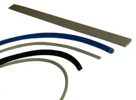
Illustrative purposes only

8863-0202-93
Gasket, EMI Shielding, Round, Silicone, 9.5 mm
⚠️ Reference pricing provided. In case of supply shortages, we will connect you with our trusted procurement partners to ensure your project's continuity.
- Manufacturer: LAIRD
- Product type: Shielding Gaskets & Material
- Length: 9.5mm
- Product Range: 8863
- Shielding Type: EMI Shielding
- Gasket Material: Silicone
| Delivery and price | |
|---|---|
| Units per pack | 250 |
| Price | 49.82 € |
| Current stock | 10+ |
| Lead time | 30 days |
Datasheet

**EMI** C A T A L O G

## ABOUT **LAIRD**

Laird is a global technology business focused on enabling wireless communication and smart systems, and providing components and systems that protect electronics. Laird operates through two divisions, Wireless Systems and Performance Materials. Wireless Systems solutions include antenna systems, embedded wireless modules, telematics products and wireless automation and control solutions. Performance Materials solutions include electromagnetic interference shielding, thermal management and signal integrity products. As a leader in the design, supply and support of innovative technology, our products allow people, organisations, machines and applications to connect effectively, helping to build a world where smart technology transforms the way of life. Custom products are supplied to major sectors of the electronics industry including the handset, telecommunications, IT, automotive, public safety, consumer, medical, rail, mining and industrial markets. Providing value and differentiation to our customers though innovation, reliable fulfilment and speed, Laird PLC is listed and headquartered in London, and employs over 9,000 people in more than 58 facilities located in 18 countries. .

**==> picture [516 x 98] intentionally omitted <==**

## TABLE OF **CONTENTS**

|TABLE OF**CONTENTS**|**CONTENTS**|
|---|---|
|**EMI INTRODUCTION**|2|
|**EMI SUMMARY**|3|
|**BOARD LEVEL SHIELDS**|6|
|Product Selection Guide<br>Introduction<br>Standard Design Shields|6<br>8<br>9|
|EZ Peel™|11|
|Rigid Corner|11|
|ReCovr™|12|
|ReMovl|12|
|Overview|13|
|**FINGERSTOCK**|14|
|Product Selection Guide|14|
|Introduction|15|
|Mounting Methods|16|
|Ordering Information|17|
|UltraSoft®Series|18|
|Recyclable Clean Copper|18|
|Slot Mount Series|19|
|Dual Slot Series|21|
|Teardrop Series|21|
|Compact PCI Symmetrical Mount|22|
|Alternate Slot Series|22|
|Variable Slot Mount|23|
|Symmetrical (S3) Slotted Shielding|24|
|Solid Top (S3) Symmetrical Slotted Shielding|25|
|Clip-On Symmetrical Shielding|26|
|No Snag Gasket|27|
|All-Purpose Series|28|
|Clip-On Series|29|
|Low Profile Hook-On Gasket|31|
|Low Profile Gasket|31|
|Large Enclosure Series|32|
|Double-Sided Contact Series|32|
|Foldover Series|33|
|Stainless Steel I/O Shielding|33|
|Flexible Low Compression Series|34|
|Clip-On Twist Series|34|
|Twist Series|35|
|Divider Edge Shielding|35|
|Card Guide Clip-On|36|
|Clip-On Perpendicular Shielding<br>Clip-On Perpendicular Grounding Strip<br>Clip-On Longitudinal Grounding Strip<br>Mini-Longitudinal Grounding Gasket<br>Longitudinal Grounding Series<br>Custom Stamping<br>Contact Strips / Contact Rings<br>IEEE 1394 Horizontal Connector Gasket|36<br>37<br>37<br>38<br>38<br>39<br>39<br>39|
|DIN Connector Series|39|
|USB Connector|40|


|Fiber Optic Shield|40|
|---|---|
|GBIC Fiber Optic Shield|40|
|"D" Connector Shielding / Slotted "D"|41|
|Precision Stamped Metals|42|
|Contacts|42|
|Custom Design|44|
|Metals Galvanic Compatibility Chart|46|
|**VENT PANELS**|48|
|MaxAir™|49|
|Elecro-Air™|50|
|Electrovent™|51|
|**FABRIC-OVER FOAM**|52|
|Product Selection Guide|52|
|Introduction|54|
|EcoGreen™|56|
|I/O / Gasket Selection Guide|57|
|Profile Selection Guide|58|
|I/O Selection Guide|62|
|Knitted Conductive Gaskets|65|
|Visual Part Reference Guide|66|
|Part Number Cross Reference|67|
|Ultraflex®|68|
|All Mesh|69|
|Elastomer Core|70|
|Electroground®EMI Washers|72|
|Electromesh®Tape|75|
|Conductive Fabric|76|
|MRI "A" Fabric|77|
|Conductive Tape|78|
|**ELECTRICALLY CONDUCTIVE ELASTOMERS**|79|
|Introduction|79|
|Product Selection Guide|80|
|Case Study|81|
|Visual Part Reference Guide|85|
|Electroseal™Conductive Elastomer|86|
|Extrusions Guide|87|
|Gemini™Coextrusions|93|
|Fabricated Components Guide|95|
|Metal Impregnated Materials|99|
|Specialty Products|102|
|Automated Form-In-Place Gaskets|103|
|**MICROWAVE ABSORBERS**|105|
|Product Selection Guide|105|
|Design Guide|106|
|Q-Zorb®2000 HF|109|
|Q-Zorb®3000 HP|110|
|RFRET 4000|111|
|RFLS 5000|112|
|Analysis, Test and Prototype Development|113|


**www.lairdtech.com**

## TABLE OF **CONTENTS**

|TABLE OF**CONTENTS**|**CONTENTS**|
|---|---|
|**EMI INTRODUCTION**|2|
|**EMI SUMMARY**|3|
|**BOARD LEVEL SHIELDS**|6|
|Product Selection Guide<br>Introduction<br>Standard Design Shields|6<br>8<br>9|
|EZ Peel™|11|
|Rigid Corner|11|
|ReCovr™|12|
|ReMovl|12|
|Overview|13|
|**FINGERSTOCK**|14|
|Product Selection Guide|14|
|Introduction|15|
|Mounting Methods|16|
|Ordering Information<br>UltraSoft®Series|17<br>18|
|Recyclable Clean Copper|18|
|Slot Mount Series|19|
|Dual Slot Series|21|
|Teardrop Series|21|
|Compact PCI Symmetrical Mount|22|
|Alternate Slot Series|22|
|Variable Slot Mount|23|
|Symmetrical (S3) Slotted Shielding|24|
|Solid Top (S3) Symmetrical Slotted Shielding|25|
|Clip-On Symmetrical Shielding|26|
|No Snag Gasket|27|
|All-Purpose Series|28|
|Clip-On Series|29|
|Low Profile Hook-On Gasket|31|
|Low Profile Gasket|31|
|Large Enclosure Series|32|
|Double-Sided Contact Series|32|
|Foldover Series|33|
|Stainless Steel I/O Shielding|33|
|Flexible Low Compression Series|34|
|Clip-On Twist Series|34|
|Twist Series|35|
|Divider Edge Shielding|35|
|Card Guide Clip-On|36|
|Clip-On Perpendicular Shielding<br>Clip-On Perpendicular Grounding Strip<br>Clip-On Longitudinal Grounding Strip<br>Mini-Longitudinal Grounding Gasket<br>Longitudinal Grounding Series<br>Custom Stamping<br>Contact Strips / Contact Rings<br>IEEE 1394 Horizontal Connector Gasket|36<br>37<br>37<br>38<br>38<br>39<br>39<br>39|
|DIN Connector Series|39|
|USB Connector|40|


|Fiber Optic Shield|40|
|---|---|
|GBIC Fiber Optic Shield|40|
|"D" Connector Shielding / Slotted "D"|41|
|Precision Stamped Metals|42|
|Contacts|42|
|Custom Design|44|
|Metals Galvanic Compatibility Chart|46|
|**VENT PANELS**|48|
|MaxAir™|49|
|Elecro-Air™|50|
|Electrovent™|51|
|**FABRIC-OVER FOAM**|52|
|Product Selection Guide|52|
|Introduction|54|
|EcoGreen™|56|
|I/O / Gasket Selection Guide|57|
|Profile Selection Guide|58|
|I/O Selection Guide|62|
|Knitted Conductive Gaskets|65|
|Visual Part Reference Guide|66|
|Part Number Cross Reference|67|
|Ultraflex®|68|
|All Mesh|69|
|Elastomer Core|70|
|Electroground®EMI Washers|72|
|Electromesh®Tape|75|
|Conductive Fabric|76|
|MRI "A" Fabric|77|
|Conductive Tape|78|
|**ELECTRICALLY CONDUCTIVE ELASTOMERS**|79|
|Introduction|79|
|Product Selection Guide|80|
|Case Study|81|
|Visual Part Reference Guide|85|
|Electroseal™Conductive Elastomer|86|
|Extrusions Guide|87|
|Gemini™Coextrusions|93|
|Fabricated Components Guide|95|
|Metal Impregnated Materials|99|
|Specialty Products|102|
|Automated Form-In-Place Gaskets|103|
|**MICROWAVE ABSORBERS**|105|
|Product Selection Guide|105|
|Design Guide|106|
|Q-Zorb®2000 HF|109|
|Q-Zorb®3000 HP|110|
|RFRET 4000|111|
|RFLS 5000|112|
|Analysis, Test and Prototype Development|113|


**www.lairdtech.com**

EMI ESSENTIALS

**EMI INTRODUCTION**

## **Overview of EMC/RFI Issues**

The phenomenon of electromagnetic interference (EMI) is familiar to virtually everyone, even if they do not understand the underlying principles. Most people have witnessed firsthand the effects of interference. To control EMI, government organizations, such as the FCC, CSA, and EEC, mandate that manufacturers may not design, produce or sell electronic equipment that jams the public broadcast services. In other instances, however, EMI can constitute more than a mere nuisance. The military and medical communities, for example, require trouble-free operation of their electronic equipment in adverse electromagnetic environments since malfunctions could jeopardize missions and personnel.  The European Union’s EMC directive also mandates that “the apparatus has an adequate level of intrinsic immunity to electromagnetic disturbance to enable it to operate as intended”.

## **EMC Design of High Speed Systems**

The interference and susceptibility (immunity) effects of electronic apparatus are created by time-variant electromagnetic fields which may be propagated along a conducting medium or by radiation through space. Because the source of the conducted and radiated interference energy levels may be related, a coordinated systems design effort is required to reduce these effects.

A design program for an equipment item that must meet both an emission and an immunity requirement consists of:

- Suppression: Reducing the interference at its source.

- Isolation: Isolating the offending circuits by filtering, grounding and shielding.

- Desensitization: Increasing the immunity of any susceptible circuits.

These three steps should be carried on throughout the entire equipment design and implemented as early as possible within the design program.

## **Effects of Logic Speed**

The trend in today’s electronic devices is faster, smaller, and digital rather than analog. Most equipment (95%) of today contains digital circuits. Today’s digital designer must create a circuit board that has the lowest possible EMI, combined with the highest possible operating/processing speeds. Design of the PCB is the most critical EMC influencing factor for any system, since virtually all active devices are located on the board. It is the changing current (accelerated electron movement) produced by the active devices that result in EMI.

## **Design Approaches**

There are two approaches that can be used to reduce the emission from the PC board. The first approach is to operate the circuit at the slowest speeds consistent with the functionality of the system, lay out the PCB with the smallest possible loop areas (especially the high speed devices), and insert suppression components such as filters, ferrite beads, and bypass capacitors into the circuit to reduce its bandwidth. These techniques will result in a desired decrease in the high frequency harmonic amplitudes and circuit bandwidth and a corresponding undesired decrease in both the operating speed and system reliability. The use of slower speeds with reduced bandwidth will help to desensitize the circuit to external susceptibility fields.

The second is to use shielding. Shielding is the only non-invasive suppression technique. Since the shielding is not inserted into the circuit, it does not affect the high frequency operating speed of the system, nor does it affect the operation of the system should changes be made to the design in the future. In addition, shielding does not create timing problems and waveform distortion; it does not decrease system reliability; and it reduces crosstalk. Plus, shielding works for both emission suppression as well as susceptibility (immunity) problems.

Even with the overall advantages of shielding, the most cost-effective approach is to use a combination of circuit suppression/hardening and shielding.

2

**www.lairdtech.com**

||Fabric-Over-Foam and Conductive Foam||Wire Mesh|Tape|
|---|---|---|---|---|
|**Applications**|• Shielding or grounding of computer and<br>telecommunication equipment seams<br>and apertures||• Covers opened infrequently for servicing<br>(6-12 times per year)<br>• Long lasting resiliency is ideal for highly<br>sensitive components in permanent or<br>semi-permanent enclosures<br>• Consistent point-to-point contact for high<br>shielding effectiveness over the life of the<br>gasket|• Design flexibility provides grounding and<br>shielding solutions for I/O shielding panels,<br>disk drive insulators, ground planes or circuit<br>boards, electromedical devices, keyboard<br>devices<br>• Mask-and-peel tape for painted electronic<br>enclosures<br>• Cable and wire harness wrapping|
|**Features and Benefits**<br>Product Highlights|• UL 94VO and HB flame retardant<br>• Ideal for applications requiring low<br>pressure force<br>• Self-terminating cut-to lengths<br>• High conductivity and shielding attenuation<br>• Galvanically-compatible with most mating<br>surfaces<br>• High abrasion and shear resistance||• Most economical gasket for low-cycling<br>applications<br>• High shielding effectiveness over broad<br>frequency range<br>• Available in wide variety of sizes and shapes<br>• Knit construction for long lasting resiliency<br>• Versatile mounting options<br>• Available with elastomer gasket for moisture<br>and dust sealing|• Simple installation<br>• Ideally suited for thin or low-profile<br>applications<br>• Conductive foil tape with release mask for<br>painted enclosures<br>• Tin copper cloth and nickel copper cloth<br>versions provide easy-to-handle alternatives<br>to foils|
|**Electrical Shielding**<br>**Effectiveness**<br>Transfer Impedance (500 MHz)|>85 dB|90 - 105 dB<br>~~OO~~||—|
|H-field (200 MHz)<br>Modified Mil 285<br>Plane Wave (2 GHz)<br>Modified Mil 285|30 - 45 dB<br>90 - 100 dB|55 - 65 dB<br>—<br>80 - 115 dB<br>85 - 95 dB<br>~~Co~~<br>~~CS~~|||
|Surface Resistivity<br>Volume Resistivity|<0.07 ohms/square<br>N/A|N/A<br>Low surface resistivity based on material selection<br>0.0004 - 0.114 ohm-cm<br>N/A<br>~~PO~~<br>~~PO~~|||
|**Mechanical**<br>Available Size Range|Height: 0.015 - 0.945 (0,038 - 24,0)||Height: 0.062 - 0.500 (1,57 - 12,7)|Width: 0.025 - 2.00 (6,4 - 50,8)<br>Thickness: 0.003 - 0.007 (0,08 - 0,18)|
|Deflection Operating Range|20 - 75% deflection|20 - 70% deflection<br>~~OC~~||N/A|
|Compression Force<br>(based on shape selection)|3 - 10 Ibs/in. ft. (4,5 - 15,0 Kg/m)<br>@ 20% deflection (dependent on foam<br>selection and shape)||From 6 - 50 Ibs/in. ft.<br>(8,8 - 74 Kg/m) round|N/A|
|Compression Set|<4 - 20% @ 50% deflection|10% @ 20% compression<br>N/A<br>~~PO~~|||
|Joint Unevenness<br>Accommodation<br>Compound/Material<br>Availability|0.020 - 0.050 (0,51 - 1,27)<br>Cover: Flame retardant metallized Ni/Cu,<br>Tin/Cu and silver woven or non-woven textile.<br>Core: Flame retardant urethane, TPE|0.010 - 0.300 (0,25 - 7,6)<br>N/A<br>BeCu, Monel, aluminum, tin-plated steel,<br>tin-plated brass, Enviroseal version with<br>neoprene or silicone<br>Tin-plated copper, copper foil, nickel copper<br>cloth tape<br>~~Co~~|||
|Temperature Range|-40 - 158°F (-40 - 70°C)|Enviroseal -103 - 500°F (-75 - 260°C)<br>50 - 500°F (10 - 260°C) based on material<br>selection<br>~~CS~~|||
|Available Profiles|Round, rectangular, square “D”, “C”, “J”, “P”,<br>“U”, clip-on, knife edge|Round, rectangular, square, single-round with<br>fin, double-round with fin<br>~~OC~~||Rolls|
|Mounting Methods|Groove, PSA, clip-on, dart|Groove, pressure-sensitive adhesive,<br>mechanical fasteners, channel mount<br>Pressure-sensitive adhesive, conductive or<br>non-conductive<br>~~OC~~|||
|Custom Shapes Available|Cut-to lengths, mitered and spliced corners,<br>kiss-cut, other profiles|Cut-to lengths, mitered corners, flat tape, and<br>EMI washers<br>~~OO~~||Die-cut shapes|
|**Environmental**<br>Fluid Seal|N/A|Enviroseal product only: moisture, rain<br>~~OO~~||N/A|
|Air/Dust|Provides barrier against dust|Enviroseal product only<br>N/A<br>~~Po~~|||
|Galvanic Compatibility|Compatible with a wide variety of mating<br>surfaces—zinc, aluminum, stainless steel, etc.|Variety of platings to ensure galvanic<br>compatibility with mating surface<br>~~Oe~~||3<br>Wide variety of materials available to meet<br>galvanic compatibility requirements|


- Design flexibility provides grounding and shielding solutions for I/O shielding panels, disk drive insulators, ground planes or circuit boards, electromedical devices, keyboard devices

**www.lairdtech.comwww.lairdtech.com**

|Applications|Fingerstock<br>• Ideal for high-cycling applications requiring<br>frequent access<br>• Ideal in wiping applications when gasket needs<br>to be engaged from either the top or side<br>• Wide variety of profiles and mounting methods<br>accommodating applications from small hand-<br>held devices to room-size enclosures<br>A,<br>FY<br>A|Fingerstock<br>• Ideal for high-cycling applications requiring<br>frequent access<br>• Ideal in wiping applications when gasket needs<br>to be engaged from either the top or side<br>• Wide variety of profiles and mounting methods<br>accommodating applications from small hand-<br>held devices to room-size enclosures<br>A,<br>FY<br>A|Board-Level Shields<br>Vent Panels and Filters<br>• All applications that require shielding of<br>board- level components<br>• Low height down to 0.04 (1,0)<br>accommodating mother/daughter board<br>configurations<br>• Secure cover design ideal for applications<br>subject to shock and vibration such as<br>mobile military vehicles, commercial aircraft,<br>and wireless electronics<br>• Provides air flow for component cooling and a barrier to<br>reduce RF leakage<br>• Sizes range from small muffin fans on desktops to large<br>room-size facilities<br>• Available in commercial and military grade materials<br>wW<br>~~oo~~|Board-Level Shields<br>Vent Panels and Filters<br>• All applications that require shielding of<br>board- level components<br>• Low height down to 0.04 (1,0)<br>accommodating mother/daughter board<br>configurations<br>• Secure cover design ideal for applications<br>subject to shock and vibration such as<br>mobile military vehicles, commercial aircraft,<br>and wireless electronics<br>• Provides air flow for component cooling and a barrier to<br>reduce RF leakage<br>• Sizes range from small muffin fans on desktops to large<br>room-size facilities<br>• Available in commercial and military grade materials<br>wW<br>~~oo~~|
|---|---|---|---|---|
|Features and Benefits<br>Product Highlights|• Large selection of sizes and shapes<br>• Wide mechanical operating range||• Custom shapes available<br>• Provides isolation of board-level|• Available in a wide range of materials and platings<br>that meet a broad range of shielding effectiveness|
||• Superior performance at elevated temperatures<br>• High shielding effectiveness levels<br>• Ideal for high-cycle applications<br>• Good design flexibility with either wiping action<br>or in compression||components<br>• Minimizes crosstalk and susceptibility<br>without impacting system speed<br>• Available in tape-and-reel for automated<br>pick-and-place applications|requirements<br>• Varied mounting configurations meeting<br>environmental space criteria<br>• Available protective grille for high traffic areas<br>• Provides cooling of electronic equipment while|
||• For use in a wide variety of slotted and<br>grounding contact applications||• ReCovr/ReMovl features available for<br>convenient component access.|maintaining EMI integrity of enclosure<br>• MaxAir vent panels offer 10-20% additional airflow<br>over frames Al vent panels|
|**Electrical Shielding**|80 - 100 dB||—|—|
|**Effectiveness**|||||
|Transfer Impedance (500 MHz)|||||
|H-field (200 MHz)<br>Modified Mil 285|60 - 70 dB||48 dB|40 - 70 dB|
|Plane Wave (2 GHz)<br>Modified Mil 285|75 - 120 dB||40 - 60 dB|45 - 115 dB|
|Surface Resistivity|N/A||N/A|N/A|
|Volume Resistivity|N/A||N/A|N/A|
|**Mechanical**<br>Available Size Range|Selection of various sizes and configurations<br>to accommodate gaps from 0.010 - 0.400|Selection of various sizes and configurations|Fence and lid: 0.130 - 1.00 (3,3 - 25,4) height<br>6.000 (152,4) width|Thickness: 0.25 - 0.500 (6,35 - 12,7)|
||(0,25 - 10,2)||One-piece construction: 0.04 - 0.25 (1,0 - 6,4)<br>height, 0.250 - 0.375 (6,35 - 9,53) width||
|Deflection Operating Range|20 - 80% deflection,<br>Maximum deflection is dependent on the part<br>profile||N/A|N/A|
|Compression Force|UltraSoft®98 Series: 1.6 Ibs/in. ft.||N/A|N/A|
|(based on shape selection)|(2,4 Kg/m) to 41 Ibs/in. ft. (61 Kg/m)||||
||Standard 97 Series: 3.1 Ibs/in. ft.||||
||(4.6 Kg/m) to 118 Ibs/in. ft. (176 Kg/m)||||
|Compression Set|None within operating range||N/A|N/A|
|Joint Unevenness|0.003 - 0.350 (0,08 - 8,89) maximum||N/A|N/A|
|Accommodation|||||
|Compound/Material|Standard material is Beryllium Copper, other|Standard material is Beryllium Copper, other|Tin-plated phosphor bronze, tin-coated steel,|Gasket material: Monel, tin/copper/steel, BeCu,|
|Availability|beryllium free variants on request||stainless steel, brass, BeCu, and nickel silver;|metallized fabric-over-foam|
||||other materials also available|Fingerstock frame: aluminum alloy, steel, brass|
|||||Honeycomb material: aluminum, steel, brass,|
|||||metallized polymeric|
|Temperature Range|Continuous operation @ 250°F (121°C)||Withstands reflow and solder temperature|N/A|
|Available Profiles|Over 350 standard shapes available, as well<br>as cut-to lengths and modified standards that<br>include finger removal, notches, punch holes, etc.||Squares, rectangles, L-shapes, 90° inside<br>corners, and other custom shapes|N/A|
|Mounting Methods|Clip-on, Sticky Fingers®(pressure-sensitive||Surface mount/thru-hole, various pin styles|Captive fastener thru-holes|
||adhesive tape), rivet, weld, solder, and slot mount||available||
|Custom Shapes Available|Custom designs to meet specific applications||Flexible fence with flat lid, photo etched<br>flat blanks for hand forming, solid can<br>construction, supplied with dividers to provide<br>isolation|Available in circular configurations and<br>custom shapes|
|**Environmental**|None||N/A|Drip-proof versions available|
|Fluid Seal|||||
|Air/Dust|Limited to twist series with Poron seal||N/A|95% open area for minimal pressure drop|
|4<br>Galvanic Compatibility|Over 20 plating finishes available to ensure<br>galvanic compatibility with mating surface||Compatible with all solder materials|Gasket materials compatible with wide variety of<br>plated surfaces|


**www.lairdtech.com**

|_e738|Form-In-Place<br>Electrically Conductive Elastomers<br>Oriented Wire<br>• Ideal for applications with miniature<br>electrical housings, thin wall<br>construction, and intricate multi-<br>components (i.e., cell phones, hand-<br>held devices, medical instrumentation<br>• EMI and environmental sealing applications<br>where flat or groove mounting surface re-<br>quires a complex molded or extruded shape<br>• Providing both EMI shielding and an<br>environmental seal on cast or machined<br>surfaces<br>• Vulcanized frame configurations can be<br>used with pre-cast housings, vent panels,<br>e738@|Form-In-Place<br>Electrically Conductive Elastomers<br>Oriented Wire<br>• Ideal for applications with miniature<br>electrical housings, thin wall<br>construction, and intricate multi-<br>components (i.e., cell phones, hand-<br>held devices, medical instrumentation<br>• EMI and environmental sealing applications<br>where flat or groove mounting surface re-<br>quires a complex molded or extruded shape<br>• Providing both EMI shielding and an<br>environmental seal on cast or machined<br>surfaces<br>• Vulcanized frame configurations can be<br>used with pre-cast housings, vent panels,<br>e738@|Form-In-Place<br>Electrically Conductive Elastomers<br>Oriented Wire<br>• Ideal for applications with miniature<br>electrical housings, thin wall<br>construction, and intricate multi-<br>components (i.e., cell phones, hand-<br>held devices, medical instrumentation<br>• EMI and environmental sealing applications<br>where flat or groove mounting surface re-<br>quires a complex molded or extruded shape<br>• Providing both EMI shielding and an<br>environmental seal on cast or machined<br>surfaces<br>• Vulcanized frame configurations can be<br>used with pre-cast housings, vent panels,<br>e738@|Microwave Absorbers<br>• Antenna sidelobe reduction<br>• Surface current suppression<br>• Applied directly to the top of high-speed<br>CPUs, LSIs, and ICs<br>• Crosstalk suppression<br>@|Microwave Absorbers<br>• Antenna sidelobe reduction<br>• Surface current suppression<br>• Applied directly to the top of high-speed<br>CPUs, LSIs, and ICs<br>• Crosstalk suppression<br>@|
|---|---|---|---|---|---|
||and equipment)||and computer terminal window frames|• Improves antenna gain in RFID||
||||• Die-cut wall widths as low as 0.090||applications|
||||(2,27) for circular military connectors<br>and D-sub connectors|• Radar cross-section reduction||
||• Automated process offers cost savings<br>on raw material, labor and assembly time<br>• Small dimension which provide critical<br>packaging space for board level<br>components<br>• Fast prototyping and turn over to mass<br>production<br>• Various bead size and cross section<br>shape available<br>• Dispense on metal or plastics<br>85 - 120 dB|• Meets military and commercial standards<br>• Provides EMI and environmental shielding<br>• Extruded shapes ideal for extremely narrow<br>mounting surfaces<br>• Custom die-cut and molding available<br>• Wide variety of material compounds for<br>galvanic compatibility to mounting surfaces<br>• High corrosion-resistant compounds available<br>40 - 105 dB<br>~~a~~|• Provides both EMI and moisture seal<br>• Available in sponge or solid silicone with<br>Monel or aluminum wire<br>• Can be die-cut in complex shapes<br>• Monel wire bonded into the silicone<br>provides multiple spring effect with each<br>contact point resulting in low compres-<br>sion set<br>60 - 100 dB|• Higher frequency use than traditional shielding<br>• Frequency range extended used with other<br>shielding<br>• Variety of types for custom solutions<br>• Easy installation into noisy cavities<br>with pressure-sensitive adhesive<br>• EMI and radar cross-section reduction<br>• Internal EMI and cavity resonance reduction,<br>used in conjunction with board-level shielding<br>N/A||
||50 - 70 dB|30 - 75 dB|25 - 60 dB|N/A||
||70 - 100 dB<br>N/A<br>0.002 - 0.03 ohm-cm|40 - 120 dB<br>N/A<br>0.002 - 5 ohm-cm<br>~~EE~~|30 - 95 dB<br>N/A<br>0.006 ohm-cm|N/A<br>N/A<br>N/A||
||Height: 0.014 - 0.090 (0,36 - 2,3)<br>Width: 0.020 - 0.125 (0,5 - 3,1)|Sheet: 0.020 (0,51) - 0.125 (3,17) thick<br>O-strip: 0.040 (1,02) - 0.250 (6,35) dia.<br>O-tubing: 0.090 (2,28) O.D. x 0.050 (1,27) I.D.<br>to 0.4371 (11,10) O.D. x 0.250 (6,35) I.D.<br>~~ee~~|Thickness: 0.032 - 0.250 (0,81 - 6,35)|Offered in sheets as a die-cut or kiss-cut<br>component||
||15 - 20% deflection<br>Sheet: 10% deflection<br>Solid extrusions: 10 -25% deflection<br>Hollow extrusions: 20 - 50% deflection<br>1.5 Ibs/in. ft. (0,27 Kg/cm) @<br>0.222 (0,56) height @ 20% deflection<br>Sheet: 75 - 100 PSI (516,7 - 689 kPa)<br><20% @ 50% deflection<br>15 - 50% @ 50% deflection<br>0.002 - 0.006 (0,05 - 0,15)<br>Sheet: 0.005 - 0.010 (0,13 - 0,25)<br>Tubing: 0.005 - 0.300 (0,13 - 7,6)<br>Elastomer silicone fillers: Ag/Al, Ag/<br>Cu, Ag/Ni, Ni/graphite<br>Compounds that meet MIL-G-83528:<br>Elastomers: silicone, fluorosilicone, EPDM<br>Fillers: Ag, Ag/Cu, Ag/Al, Ag/Ni, Ag/Gl, CAR,<br>Ni/graphite.<br>Available in NASA-specified ES75 compounds<br>for outgassing<br>-58 - 212°F (-50 - 100°C)<br>-67 to 302°F (-55 to 150°C)<br>“D” shape bead<br>Solid extrusions: rectangular, round ,“D”, and U-channel<br>Hollow extrusions: square, round, “D”, “P”, modified<br>standards, cut-to length sheets<br>Directly applied to mounting surface<br>Groove, pressure-sensitive adhesive, channel<br>clip- on, mechanical fastening<br>Infinite variety of patterns and larger<br>custom bead sizes<br>Large variation on extruded shapes, complex<br>die-cuts, and molded parts<br>~~OB~~<br>~~oOa~~<br>~~a~~<br>~~Ooa~~||10 - 20% deflection<br>25 - 100 PSI<br>(125 - 689 KPa)<br>2 - 5% @ 50 PSI (344,5 KPa)<br>0.005 - 0.015 (0,13 - 0,38)<br>Elastomer: solid or sponge silicone<br>Wire: Monel, aluminum<br>80 - 500°F (26 - 260°C)<br>Rectangular, strip, flat sheets; die-cut<br>shapes<br>Groove, pressure-sensitive adhesive<br>Complex die-cut shapes, bonded or<br>vulcanized|N/A<br>N/A<br>N/A<br>N/A<br>Microwave absorbing elastomers (Q-Zorb)<br>are offered in silicone; microwave absorber<br>foam is urethene-based, open-celled foam<br>Q-Zorb: -85 - 350°F (-65 - 175°C)<br>RF foam: -85 - 250°F (-65 - 120°C)<br>Q-Zorb thickness: 0.006 - 0.375 (0,15 - 9,53)<br>RF Foam thickness: 0.125 - 0.250 (3,18 - 6,35)<br>Pressure-sensitive adhesive<br>Infinite die-cut shapes and molded parts||
||Moisture, rain seal|Moisture, rain, jet fuel, and nuclear biological<br>chemical(NBC)UL compounds<br>~~a~~|Moisture and rain|Moisture, rain, jet fuel, and nuclear<br>biological chemical(NBC)UL compounds||
||In limited applications<br>Available in four compounds to provide<br>galvanic compatibility with most mating<br>materials|Excellent sealing against air and dust<br>21 standard variations<br>~~a~~|Provides barrier against dust<br>Monel and aluminum wire are compatible<br>with a broad range of mating surfaces|5<br>Available in limited applications<br>Moisture, rain, jet fuel, and nuclear<br>biological chemical (NBC) UL compounds||


**www.lairdtech.com**

All dimensions are in inches (millimeters) unless otherwise specified.

EMI ESSENTIALS

## **BOARD LEVEL SHIELDS** PRODUCT SELECTION GUIDE

**==> picture [592 x 628] intentionally omitted <==**

**----- Start of picture text -----**<br>
|||||||
|---|---|---|---|---|---|
|Corner Feature|
|Traditional|Rigid|Full Drawn|Full Drawn|
|Folded|Corner|w/ Flange|Zero Flange|
|Improves Flatness|Most mechanically rigid,|Similar to Full|
|by increasing|but depth attainable is|Drawn, Tooling|
|torsional rigidity|material and configuration|more complex.|
|BLS Design|Key Attributes &|dependent|
|Type / Features|||Application Consideration|
|SINGLE PIECE|
|Single Piece|Simple low cost BLS Solution|Opt|Std|Opt (height/matl limits)|Opt|
|S|Pt|tt|
|TWO PIECE|
|Traditional|Post Reflow Component Access for|
|inspect, test, cleaning, etc. Various|
|Frame|cover retention features available|Opt|Std|Opt (height/matl limits)|Low Height|
|to address rattling, EMI, and shock/|Option|
|vibration concerns.|
|Cover|Std|Opt|Opt (height/matl limits)|N/A|
|Optional pre-assembled deliverable|
|ReCovr|Lower total cost 2 piece solution.|N/A|Req'd|N/A|N/A|
|Eaveless side wall for maximum|
|component access.|
|=|Pt|ff|
|EZ Peel|Support for legacy products.|Std|N/A|Opt|
|ReCovr can often be a more reliable|
|alternative. EZ Peel can utilize a|
|separate replacement cover if desired.|
|a|eee|
|97-2000|Large BLS Applications.  Can|
|accommodate internal walls for|
|Frame|N/A|N/A|N/A|N/A|
|EMI compartmentation.|
|Cover|Std|N/A|N/A|N/A|
|BLE|EE|
|BLS MATERIALS|
|Material Type|Description / Specs|Comments|
|MATRIX|
|CRS, Tin Plated|1010 / 1008 CRS|High Permeability Material for low Freq Applications, Very Good Solderability,|
|Mitigation options for Tin Whisker Growth, Pre-plated, Bare stamped edges|
|Nickel Silver|CA770, CA752|Environmental Performance & Aesthetic Quality, Good Mechanical /|
|Strength Properties, Good Solderability, Active Flux may be required|
|Stainless Steel|Typical 301 and 316 Series|Environmental Performance, Good option for the cover of 2 piece designs|
|Copper Alloys|Phosphor Bronze, Beryllium Copper, Brass|Can be chosen for unique requirements that integrate spring contacts,|
|6|Typically Plated for Solderability and/or corrosion resistance|

**----- End of picture text -----**<br>


**www.lairdtech.com**

EMI ESSENTIALS

|**Unique Product**<br>**Features**|**Mounting Features**|**Mounting Features**|**Mounting Features**||**Size & Shape**|**Size & Shape**|||
|---|---|---|---|---|---|---|---|---|
|ReMovl Pick &<br>Place Bridge<br>Easy removal of pick<br>and place bridge for<br>post reflow inspection<br>,<br>—<br>= ay|SMT<br>Castellations<br>.|Thru Hole<br>Loc Pins<br>Through hole style<br>pin that engages<br>to underside of<br>PCB by mechanical<br>engagement.|Pins, Tabs,<br>Etc.<br>~—<br>U ees|Interior<br>Walls|Typical<br>Material<br>Thickness|Low Height<br>(less than 2<br>mm)|Typical<br>Length<br>& Width|Flatness<br>(Size Dep)|
|N/A|Std|Opt|Opt|No|0.2|Yes|10- 75 mm|0.08|
|Opt|Std|Opt|Opt|Opt|0.2|Yes|10- 75 mm|0.08|
|N/A|N/A|N/A|N/A|N/A|0.15|Yes|10- 75 mm|0.15|
|N/A<br>N/A|Std<br>Std|N/A<br>N/A|Opt<br>Opt|No<br>No|0.12<br>0.3|Yes<br>No|10-30 mm<br>10-40 mm|0.1<br>0.1|
|N/A|Std|Opt|Opt|Opt|0.4|No|50-300 mm|0.2|
|N/A|N/A|N/A|N/A|0.25|0.25|No|50-300 mm|0.2|


## **Cost Position Applications**

Best Most common BLS solutions Good Hi Performance BLS solutions (Mechanical & Environmental) Better BLS Covers, Specialty Military Good Specialty BLS applications Integrated Spring Contacts

**==> picture [5 x 7] intentionally omitted <==**

**----- Start of picture text -----**<br>
7<br>**----- End of picture text -----**<br>


**www.lairdtech.com**

EMI ESSENTIALS **BOARD LEVEL SHIELDS**

Whether it’s a one-piece shield, multi-compartmental shield or precision contact, each solution Laird delivers is designed to provide maximum performance within a minimum timeline. Laird produces metal electronic components for surface mount applications in a variety of industries. Laird expertise in a number of key areas ensures that the part provided not only performs, but also optimizes applications. After determining the right board level shield or contact design for an application, Laird experts use the latest systems to develop part designs in just hours.

Laird experienced engineers and technical specialists look beyond the component to the total application.

They work with you to engineer the ideal finished product at the best value.

| 8

**www.lairdtech.com**

EMI ESSENTIALS

## **BOARD LEVEL SHIELDS** STANDARD DESIGN SHIELDS

## **STANDARD SURFACE MOUNT SHIELDS —**

## ONE-PIECE

## **Off the Shelf, On Spec and On Budget**

Standard surface mount shields are available in both one-piece and two-piece designs. One-piece shields offer six sides of protection, with the sixth side being the board itself. One-piece designs offer economical shielding protection where access to covered components is not necessary. There are no tooling costs associated with either the one and/or two-piece standard design.

## **TYPICAL PROPERTIES AND PERFORMANCE**

## **Features and Benefits:**

## ALL PART NUMBERS

• Available in both one-piece and two-piece designs • One-piece designs offer economical shielding protection

PROPERTY TEST METHOD RESULT and two-piece designs Co-planarity LTWI-1119 < 0.10 mm • One-piece designs offer economical Solderability ANSI/JSTD-002 >99% shielding protection • No tooling costs associated with one Solderability MIL-STD-202 Method 208 >99% or two-piece standard designs Surface mount solderability ANSI/EIA 638 Passes Appearance LTIES-125 Passes Adhesion ASTM B-571 Passes 3 Axis mechanical shock LTES-461 Passes STANDARD ONE-PIECE BOARD LEVEL SHIELDS PART MAXIMUM MAXIMUM MAXIMUM PARTS NUMBER OVERALL OVERALL OVERALL PER REEL LENGTH WIDTH HEIGHT in (mm) in (mm) in (mm) BMI-S-101 .538 .476 .100 1000 (13,66) (12,10) (2,54) BMI-S-102 .650 .650 .142 700 (16,50) (16,50) (3,60) BMI-S-103 1.032 1.032 .200 300 (26,21) (26,21) (5,08) BMI-S-104 1.260 1.260 .236 225 (32,00) (32,00) (6,00) BMI-S-105 1.500 1.000 .236 250 (38,10) (25,40) (6,00) BMI-S-106 1.450 1.326 .200 300 (36,83) (33,68) (5,08) BMI-S-107 1.747 1.747 .384 120 (44,37) (44,37) (9,75) BMI-S-111 1.032 1.032 .079 625 (26,21) (26,21) (2,00) ~~os~~ . 9 **www.lairdtech.com** —_

EMI ESSENTIALS

## **BOARD LEVEL SHIELDS** STANDARD DESIGN SHIELDS

## **STANDARD SURFACE MOUNT SHIELDS —**

## **TWO-PIECE**

## **Reduce Board Damage From Inspection and Repairs**

Two-piece board level shields offer users the flexibility to inspect or repair shielded components without having to risk board damage by removing the entire shield or incur any tooling costs. Covers snap on and off with ease, which makes repair of the component under the shield quicker and easier and reduces board re-work. Two-piece shields are available unassembled*, and are designed to survive drop, shock and no-rattle tests.

*Pre-assembly is an option. Consult sales

## **STANDARD TWO-PIECE BOARD LEVEL SHIELDS**

||**STANDARD TWO-PIECE BOARD LEVEL SHIELDS**|**STANDARD TWO-PIECE BOARD LEVEL SHIELDS**|**STANDARD TWO-PIECE BOARD LEVEL SHIELDS**||||
|---|---|---|---|---|---|---|
||PART<br>NUMBER<br>OVERALL<br>LENGTH<br>in (mm)<br>OVERALL<br>WIDTH<br>in (mm)<br>OVERALL<br>HEIGHT<br>in (mm)<br>PARTS<br>PER REEL<br>BMI-S-201-F<br>.538<br>(13,66)<br>.476<br>(12,10)<br>.100<br>(2,54)<br>1000<br>BMI-S-202-F<br>.650<br>(16,50)<br>.650<br>(16,50)<br>.142<br>(3,60)<br>700<br>~~|~~<br>~~|~~<br>~~|~~<br>~~ft~~<br>~~esa~~|||||**Features and Benefits:**<br>• Offers flexibility to inspect<br>or repair shield components<br>without risking board<br>damage<br>• Covers snap on and off<br>with ease|
||BMI-S-203-F<br>1.032<br>(26,21)<br>1.032<br>(26,21)<br>.200<br>(5,08)<br>300<br>~~a~~||||||
||BMI-S-204-F<br>1.260<br>(32,00)<br>1.260<br>(32,00)<br>.236<br>(6,00)<br>225<br>BMI-S-205-F<br>1.500<br>(38,10)<br>1.000<br>(25,40)<br>.236<br>(6,00)<br>250<br>~~>~~||||||
||BMI-S-206-F<br>1.450<br>1.326<br>.200|300|||||
||(36,83)<br>(33,68)<br>(5,08)||||||
||BMI-S-207-F<br>1.747<br>(44,37)<br>1.747<br>(44,37)<br>.384<br>(9,75)<br>120<br>~~a~~||||||
||BMI-S-209-F<br>1.156<br>0.728<br>.275|400|||||
||(29,36)<br>(18,50)<br>(7,00)||||||
||BMI-S-210-F<br>1.732<br>1.201<br>.118|370|||||
||(44,02)<br>(30,50)<br>(3,00)||||||
||BMI-S-230-F<br>1.500<br>(38,10)<br>2.000<br>(50,80)<br>.200<br>(5,08)<br>250<br>BMI-S-230-F-R<br>1.500<br>(38,10)<br>2.000<br>(50,80)<br>.200<br>(5,08)<br>250<br>BMI-S-305<br>1.500<br>(38,10)<br>1.000<br>(25,40)<br>.236<br>(6,00)<br>250<br>~~a~~<br>~~| ~~<br>~~es~~||||oe|oe|
||**DESIGN PARAMETERS – ALL PART NUMBERS**||||||
|10<br>_|PICK-UP SPOT<br>DIAMETER MATERIAL<br>MATERIAL<br>THICKNESS<br>CARRIER TAPE<br>6 mm orgreater 0,20 mm<br>CRS Tin, Nickel Silver, 300 Series SS<br>0,20 mm<br>COVER TAPE<br>MATERIAL<br>REEL<br>LTIMS-PSA<br>330 mm (101, 102, 103, 104, 201, 202, 203, 204)<br>381 mm (105, 106, 107, 205, 206, 207)<br>Plastic<br>~~———~~|||||MATERIAL<br>LTIMS-LCB<br>DIAMETER<br>EIA-481|


## **Features and Benefits:**

- Offers flexibility to inspect or repair shield components without risking board damage

- Covers snap on and off with ease

**www.lairdtech.com**

EMI ESSENTIALS

## **BOARD LEVEL SHIELDS** EZ PEEL[™]

## **PATENTED SHIELDS ARE SCORED TO ALLOW PEEL-OFF WHEN ACCESS IS NEEDED**

These patented shields have a solid top, scored to allow peel-off when access to board level components within the shield is required.

The peel-off feature prevents damage to the board and components by eliminating the need for labor intensive de-soldering, which can often result in increased scrap. Peeling off the cover is accomplished by using a small starter hole for simple removal. This hand operation requires minimal force using a hook scriber or tweezers.

After repair, replacement or adjustment of internal components, the shield can be resealed using a replacement cover. Laird offers two replacement cover options: a snap-in cover and a dish cover.

The snap-in cover utilizes a lance and hole design. The replacement cover snaps into place and locks into a lance feature on the frame of the original shield.

The other option is a dish cover that gets soldered into place on the board. The dish shape allows for self-location of the cover for soldering.

EZ Peel board level shields can be packaged in tape and reel formats for easy SMT installation using conventional pick-and-place equipment. The four standard sizes are also available without the EZ Peel (scored) feature.

## **Features and Benefits:**

- Easy removal of scored cover area

- Only requires 1.5 lbs force for cover removal

- Simple replacement technique for cover

- Use on surface mount or through-hole applications

- Shield retains all physical properties after PCMCIA/JEIDA testing for shock, bending, torque, drop and vibration

- CRS 1008/1010 (tin plated) for solderability

## RIGID CORNER

The rigid corner board-level shield incorporates a corner design that optimizes component rigidity for increased part and printed circuit board (PCB) firmness. As PCB designers are increasingly using thinner substrates, a rigid frame reinforces the assembly, thereby improving overall ruggedness and performance. The shield has improved solder joint reliability and resistance to solder joint fracture, especially in drop testing performance with thin PCBs. Several standard Laird EMI style parts including single-piece, two-piece, and multi-compartmental board-level shields use this new rigid corner design, along with availability in custom sizes as well.

The rigid corner shield is stronger and more robust than traditional formed shields, which results in coplanarity improvement of the solder castellations. The shield can tolerate more deflection (i.e., more handling) without plastic deformation. Elimination of drawn flange reduces the space needed on the PCB for shielding trace width by potentially ~0.3 mm, allowing for the shield to be more closely placed on the PCB. Elimination of draft allows for more undershield space and improved component clearance.

The partially drawn corner is located near the top portion the shield, resulting in improved torsional rigidity with no drawn lip and no draft. For parts over 2 mm, the corner is both drawn and formed with an interlocking multi-radius corner, which provides superior EMI shielding effectiveness. The interlocking corner can be meshed and closed in during the forming and drawing process for additional improved rigidity for parts taller than 2 mm. For parts under 2 mm, the entire corner is drawn without an interlocking corner.

## FEATURES

- Corner openings are reduced, improving shielding performance

- Partially drawn corner located near the top portion of the corner combined with 90° straight forming of wall sections for improved torsional rigidity.

- U.S. Patent No. 7,488,902

## MARKETS

- Computing

- Telecommunications

- Data Transfer and Information Technology

- Automotive

- Consumer Electronics

- Aerospace / Defense

- Medical

- Portability

- Industrial & Instrumentation

- Public Utilities

**==> picture [9 x 7] intentionally omitted <==**

**----- Start of picture text -----**<br>
11<br>**----- End of picture text -----**<br>


**www.lairdtech.com**

EMI ESSENTIALS

## **BOARD LEVEL SHIELDS** RECOVR[™]

The proprietary and patented ReCovr[™] product line incorporates the functionality of a two-piece shield without the need for a separate frame and cover. The shield is specially designed with a locking mechanism that allows for easy removal of the shield cover when access to board-level components is required. The locking mechanism makes repair of components under the shield quick and easy by eliminating the need for removing the entire shield and reducing board re-work. The removable top shield also integrates Laird patented rigid corner board-level shield technology, which incorporates a new corner design that optimizes component rigidity for increased part and printed circuit board (PCB) firmness.

## FEATURES

- Single-piece board-level shield with a removable top cover

- Eave-less side walls when the cover is removed

- SMT or through-hole pin configurations available

- U.S. Patent No. 7504592

- Other characteristics typical to one-piece shields: vent hole patterns, castellations, trace clearance notches, etc.

## BENEFITS

- Eliminates need for replacement covers

- Offered as an assembled product only: tape and reel, tray pack, or layer pack

- Excellent for periodic testing or rework applications.

- Limited footprint configurations (L-shapes, etc)

- Available in select Laird standard board-level sizes or custom configurations

## MARKETS OR APPLICATIONS

- Computing

- Telecommunications / Datacom

- Automotive

- Consumer Electronics

- SMART Metering

- Aerospace / Defense

- Medical

- Industrial & Instrumentation

**==> picture [260 x 89] intentionally omitted <==**

**----- Start of picture text -----**<br>
4.05 5.00  TYP<br>.159 .197<br>Po E N<br>2.70 , Poooo00ge ! 6.000<br>.106 ,}ooo00000 25.400 X .236 _ _<br>5.00  TYP 1.000<br>.197<br>9000000 2.550  TYP<br>.100 0.100 [.0<br>on5 .0932.36 TYP Looooooo 3.000  TYP - + 3.000.118  TYP<br>38.1001.500 .118 NOTE CRITICAL D<br>X<br>**----- End of picture text -----**<br>


## REMOVL[™]

The ReMovl feature incorporates the ReCovr attachment mechanism applied to the pickup bridge of a BLS frame to allow for easy, tool less detachment of the bridge after the frame is soldered to the PCB. Ease of detachment along with reliable and consistent separation force will allow for automated detachment.

## FEATURES

- Detachment is permanent – cannot be replaced like ReCovr

- Min Height: 2.0 mm (.080”) Lower heights required Product Development Review

- Top Flange Width: 1.8 mm (.071”)

- Flatness: Part Size Dependent, but typical to other Frame BLS parts

- Configurations Min 4 legs/branches required

- (see BLS Style options)

## MARKETS

   - Ideal for customer manufacturing processes where post reflow detachment of the pickup bridge is required or desired. Applications that often require the bridge to be detached include:

   - Inspection

   - Rework

   - TIM Assembly into cover

   - Cover with contact fingers to chip, etc.

   - Noise / Vibration concerns of bridge to cover

- Limitations: Must be folded or rigid corner type BLS.

- (No fully drawn parts.)

- Pull Force (Typ) 0.5 – 1.0 lbs

**Note:** Due to delicate nature of the attachment of the pickup bridge, there will be some risk to the bridge separating during pick and place operations depending on customer manufacturing processes. Pick and place head depth tolerance (z axis) -.020”

12

**www.lairdtech.com**

EMI ESSENTIALS

## **BOARD LEVEL SHIELDS**

## **INTRODUCTION**

The complexities of today's electronics pose several design challenges. Resolving EMI needs to be balanced with space, weight and production restraints. When designing a custom shielding solution, beginning in the earliest stages of the application design allows  effective elimination of EMI while meeting all specifications.

Laird board level shielding experts work through all phases of development. From design, rapid prototyping and pre-production through production and automated packaging, Laird has the experience to help speed a product to market and stay within budget.

To increase manufacturing throughout and reduce costs, Laird has developed a proprietary in-line production process that includes part formation, wash, assembly, inspection and automated packaging.

By integrating quality processes, board level shield quality and performance is ensured from design stage through final packaging. One process is the automated co-planarity inspection system. Laird replicates the customer application by measuring shields in the same plane as the printed circuit board. This is accomplished without "securing" or "touching" shields, which could throw off measurement and/or deform parts. Laird measures shields immediately prior to placement into carrier tape at speeds that match automation packing. Shield base materials include our exclusive Shield-Lite[TM] , CRS 1008/1010, beryllium copper alloys, nickel-silver alloys, copper-based alloys and spring steels. All shields are fully solderable.

## **ONE-PIECE SHIELD DESIGN**

## **LOW COST/EXCELLENT EFFECTIVENESS**

Custom surface mount shields are available in both one-piece and two-piece designs. One-piece shields provide six sides of protection, with the sixth side being the board itself. One-piece designs offer economical shielding alternatives where access to covered components for repair is not necessary.

## **TWO-PIECE SHIELD DESIGN QUICK, EASY REPAIR AND INSPECTION OF COVERED COMPONENTS**

Two-piece board level shields offer users the flexibility to inspect or repair shielded components without having to risk board damage by removing the entire shield. Covers snap on and off with ease, making repairs quicker and easier, and reducing board re-work. Two-piece shields are available pre-assembled or unassembled. Large locking dimples snap into slots on covers to provide mechanical retention force. Smaller grounding dimples provide electrical grounding for proper shielding and to prevent rattle. Two-piece shields survive drop, shock and no-rattle tests. Here are critical test results:

- Able to withstand acceleration of 4g from 10 Hz to 2000 Hz for three hours in each of three planes as per SAE J1455

- Pass EN 50 155 for railway electrical equipment including vibration test

- of 30g from 5 Hz to 200 Hz in 3 directions and a shock test with 500 m/s for 11/ms

- Pass standard telecommunications drop tests [6 faces, dropped 1 meter

- onto concrete floor]

Notice: The data set forth in all text, tables, charts, graphs and figures herein are based on samples tested and are not guaranteed for all samples or applications. Such data are intended as guides and do not reflect product specification for any specific part. Material properties are for reference only.  Product testing by purchaser is recommended to confirm.  Laird assumes no liability for product failure unless specifically stated in writing.

**==> picture [25 x 4] intentionally omitted <==**

**----- Start of picture text -----**<br>
Series 97-2100<br>**----- End of picture text -----**<br>


## **MULTI-COMPARTMENTAL SHIELD DESIGN**

## **SHIELD MULTIPLE CIRCUIT GROUPS SAVE PCB SPACE AND PRODUCTION TIME**

Multi-compartmental shields feature internal dividing walls of one material thickness and meet all on-board shield requirements for FCC, VDE, CISPR and CE. These shields are available in two-piece designs, either assembled or unassembled. Our unassembled versions allow for automatic optical inspection prior to cover placement. As in all our shielding offerings, Laird proprietary process for 100% automatic optical inspection verifies co-planarity including inner walls.

## **DRAWN BOARD LEVEL SHIELDS**

## **SEAMLESS CORNERS ADDRESS HIGH-FREQUENCY LEAKAGE**

As microprocessor speeds continue to increase, so does the potential for EMI leakage through the smallest apertures in board level shields. Laird drawn board level shields are designed to provide additional near-field and far-field circuit isolation (attenuation) at higher frequencies by eliminating the apertures found in the corners of traditional board level solutions. Drawn board level shields utilize small ground trace sizes, thereby preserving space on the circuit board.

- Solid corner designs when additional circuit isolation (attenuation) is required at higher frequencies

- Available in custom heights up to .250" (6,4 mm) with length and width dimensions from .300" (7,6 mm)  to 2.0" (50,8 mm)

- Tape and reel packaging provides an economical and automated SMT attachment method

- Available in cold rolled steel, brass, stainless steel and nickel silver

- Molded Compartment Shields and Form-In-Place elastomers can be combined with drawn board level shields to achieve shielding of multiple components with a single part

- Available with an EZ Peel scored cover feature; allows for easy top section removal for component repair and re-sealing

- Ventilation holes as needed for solder outgassing.

- Online shielding effectiveness calculator

## **SURFACE MOUNT SHIELDS MATERIAL VARIATIONS**

|RAW MATERIAL*|THICKNESS<br>in (mm)|COMMENTS|
|---|---|---|
|Cold Rolled Steel<br>1008/1010|0.005 to 0.090 (0,127<br>to 2,286)|Pre-plated Tin|
|Nickel-silver alloys|0.004 to 0.016<br>(0,102 to 0,406)|No plating required<br>for SMT<br>solderability|
|Phosphor Bronze alloys|0.004 to 0.020<br>(0,100 to 0,510)|Pre-tempered & Preplated|


*Other materials may be available, please consult sales.

**Note** : Co-planarity dependant on design

13

**www.lairdtech.com**

EMI ESSENTIALS

## **FINGERSTOCK** PRODUCT SELECTION GUIDE

**==> picture [442 x 418] intentionally omitted <==**

**----- Start of picture text -----**<br>
Application<br>Type<br>Enclosure Shielding  Continuous Length  Std. Contact Strips<br>Gaskets & Contact  (Coil Products)<br>Reverse Bend<br>Strips<br>Contact Strips<br>Double Sided<br>Contact Strip<br>Twist Series<br>Fixed Length Strips Tape Mount<br>Fold Over Series<br>Low Profile<br>Low Profile with<br>Mini-Clip On Edge Hook<br>Clip-On Mount<br>Symmetrical Large Enclosure<br>Twist Std Contact Strips<br>Contact Strips Reverse Bend<br>Reverse Bend   Contact Strips<br>Contact Strips Double Sided<br>Longitudinal   Contact Strip<br>Contacts All Purpose<br>Perpendicular /   S3 - Solid Top,<br>PCB Edge Contact Symmetrical,<br>Slotted<br>No-Snag<br>Track Mount<br>Brass Track with<br>Rivet Mount<br>Direct to Chassis /  Slot Mount Stainless Track<br>Extrusion Mount Compact PCI -   Stainless Track w/<br>Dot 10 Integral rivet<br>Variable Slot<br>Mount<br>Internal Contact<br>Contact Rings<br>External Contact<br>**----- End of picture text -----**<br>


**==> picture [180 x 112] intentionally omitted <==**

**----- Start of picture text -----**<br>
D-Sub<br>Enclosure & PCB I/O's<br>Back Plane<br>DIN Connector<br>Gaskets<br>USB<br>IEEE 1394<br>Fiber Optic<br>GBIC<br>SFP/XFP<br>**----- End of picture text -----**<br>


**==> picture [180 x 27] intentionally omitted <==**

**----- Start of picture text -----**<br>
Contact / Grounding SMT<br>**----- End of picture text -----**<br>


14

**www.lairdtech.com**

EMI ESSENTIALS **FINGERSTOCK**

Engineered metal Fingerstock solutions from Laird dates from 1938. Laird specializes in designing miniature parts of thin strip metal in quantities ranging from thousands of pieces to millions of pieces. With over 3,400 standard parts, Laird probably already has an off-theshelf solution that meets your application’s requirements.

When custom designs are needed, Laird engineering staff helps construct efficiencies in performance, cost and manufacturability from the very beginning stages of the application.

## Laird specialized capabilities:

- Assembly • Heat staking (both hand and automatic)

- Heat treating • In-house die and fixture manufacturing

- Multislide equipment • Photoetching

- Plating • Progressive die stamping

- Prototype fabrication • Resistance welding

- Riveting • Secondary fabrication

- Wire EDM

15

**www.lairdtech.com**

EMI ESSENTIALS

## **FINGERSTOCK** MOUNTING METHODS

## **UNIVERSAL MOUNTING**

A stainless steel mounting track is available for use with our full line of gasketing materials. Its unique design offers a secure mounting option versatile enough for use with fingerstock, ElectroNit[®] mesh, ElectroSeal elastomers, UltraSoft[®] Knit and fabric-over-foam products.

**==> picture [484 x 329] intentionally omitted <==**

**----- Start of picture text -----**<br>
PART NUMBER WIDTH X =  THICKNESS [MATERIAL ] (9.042)0.356<br>0095-X996-00 0.310 (7.874) 0.205 0.205<br>0095-X997-00 0.430 (10.922) (3.683)0.145 (5.207) (5.207)<br>i ry<br>0095-X998-00 0.600 (15.240)<br>s e 0.018 DETAIL “A”<br>MATERIAL THICKNESS (0.457)<br>A = 0.030 (0.762) W<br>B = 0.045 (1.143) SEE DETAIL “A”<br>C = 0.060 (1.524)<br>D = 0.090 (2.286)<br>Universal Mount E = 0.150 (3.810)<br>0.699<br>(17.755) 1.500<br>To identify proper mounting track, select width and   14.898 (38.100)<br>corresponding part number from the above chart.   se (378.409)<br>Replace the “X” with required material thickness.<br>^ Shielding gaskets may be mounted for either<br>wiping or compression closing applications.<br>Proper positioning of the shielding gasket must<br>take into consideration the closing design and<br>the configuration of the mounting surface.<br>wl & Sate<br>Rivet Mount Slot Mount<br>Laird shielding devices may be mounted quickly and easily using any of several different<br>oe ae ie<br>methods. Each installation method is described in the text that follows. However, if you should<br>run into a unique situation not resolved by any of these methods, give us a call. More than  Sticky Fingers [®] Clip-On Mounting Tape Track Mount<br>**----- End of picture text -----**<br>


To identify proper mounting track, select width and corresponding part number from the above chart. Replace the “X” with required material thickness.

Laird shielding devices may be mounted quickly and easily using any of several different oe methods. Each installation method is described in the text that follows. However, if you should run into a unique situation not resolved by any of these methods, give us a call. More than likely we can provide the exact answer you need.

## 4. Allow 24 hours minimum curing time.

## RIVET MOUNT

Riveting produces a tight, long-lasting installation. Either plastic or metal rivets may be used.

Standard parts are supplied with nonconductive tape. For rough surface applications, such as flame-sprayed surfaces, 0.010 in. (0.254 mm) thick nonconductive tape is recommended. Optional conductive tape is also available. Contact a sales department representative for additional ordering information.

## SLOT MOUNT

Slot mounted parts are easily installed using slots where bi-directional movement is required. Simply install part into one slot and snap it into the second slot or over the edge of the frame.

## CLIP-ON MOUNTING

## ADHESIVE MOUNTING

Clip-on gaskets hold firmly in place due to their own spring characteristics. Simply push the strips onto the edge or flange of the door or enclosure. Also available are clip-on gaskets with either “T” or “D” lances.

Sticky Fingers[®] is an instant, pressure-sensitive adhesive bonding system, ideal for all-purpose contact strips for metal cabinets and electronic enclosures, and is unaffected by temperatures from -67 to +250°F (-55 to +121°C).

## TAPE TRACK MOUNTING

Simply follow these four easy steps:

Stainless Steel mounting track with PSA (pressure sensitive adhesive) is available on the Symmetrical Slotted Series and Slot Mount Series.

1. Remove all grease and oily residue with solvent. Smooth the mounting surface with emery cloth.

## 2. Peel off protective paper backing.

## WELDING

3. Place gasket in correct position. (See mounting methods diagrams A through E.) Press firmly to ensure a good adhesive bond. Avoid repositioning, which might impair the effectiveness of the adhesive or may bend or kink the strip.

Welded mounting requires simple, traditional welding techniques.

## SOLDERING

Solder mounting requires normal low temperature soldering techniques, including cleaning and fluxing of parts with common copper flux materials.

NOTE: On items where fingers cover the solid portion of the gasket, pressure may be applied 16 by inserting a mandrel in the strip and pressing down. For contact strips with Magnefil[®] insert, simply press down on the fingers.

**www.lairdtech.com**

EMI ESSENTIALS

## **FINGERSTOCK** ORDERING INFORMATION

## **Part Number Format**

Example: Stock Item Unique Part No. Finish I.D. 0 0 9 7 — 0 5 2 0 — 0 2

- In the above example, Laird part number 0097-0520-02 is a 97-520 RFI/EMI shielding gasket with a bright finish

- When ordering UltraSoft[®] items, the stock item prefix will be 0098 or 0078. The above example in UltraSoft would be 0098-0520-02.

- When ordering coil, the prefix 0C should precede the stock item number; for example: 0C97, 0C98, 0C77 or 0C78

- When ordering stainless steel items, the stock item prefix will be 0095

   - 0.00005 in. (0.0013 mm) min.] but can be varied to meet your custom needs

   - Modifications to standard parts are specified by an X (following finish I.D.) for quoting only. Upon ordering, a specific part number will be assigned.

   - For tape options, see Adhesive Mounting — Sticky Fingers[®] on page 16

   - Use the catalog number for the unique part number and refer to the following chart for finish I.D.

- Standard plating finish is 0.0001 in. (0.0025 mm) min. [gold

## **Plating Finishes**

|Finish Designation|Finishes for Fingerstock Products<br>(BeCu and RCC)|Laird<br>ID|Specifications|Specification Details*|
|---|---|---|---|---|
|Unplated|Bright Finish|02|Laird Designation|Unplated, Bright or Ultrasoft surface|
||Solderable Unplated|21|Laird Designation|Solderable bright finish|
|Gold|Gold|03|ASTM B 488 / SAE AMS 2422|Type I & II, grade C, 1.27 - 2.5 µm thick|
||Gold/Nickel Underplate|10|ASTM B 488 / SAE AMS 2403|Type I & II, grade C, 1.27 - 2.5 µm thick|
|Silver|Silver (matte)|04|ASTM B 700 / QQ-S-305|Type II, grade A, 2.5 - 7.6 µm thick|
|Cadmium**|Cadmium + Yellow Chromate|05|ASTM B 766 / AMS QQ P 416|Type II, class 5, min 5 µm thick|
||Cadmium + Clear Chromate|06|ASTM B 766 / AMS QQ P 416|Type III, class 5, min 5 µm thick|
|Tin Lead**|Tin Lead [60/40] Solder|07|ASTM B 579 / SAE AMS P 81728|7.6 - 12.7 µm thick|
|Nickel|Dull Nickel|09|ASTM B 689 / SAE AMS 2403 (QQ-N-290)|2.5 - 7.6 µm thick*|
||Bright Nickel|19|ASTM B 689 / SAE AMS 2403 (QQ-N-290)|2.5 - 7.6 µm thick*|
||Sulfamate Nickel|24|ASTM B 689 / SAE AMS 2424|2.5 - 7.6 µm thick (1.27 - 2.5 µm underplate)|
|Electroless Nickel|Electroless Nickel|18|ASTM B 733 / SAE AMS C 26074|2.5 - 7.6 µm thick|
|Tin|Satin / Matte Tin|08|ASTM B 545 / MIL-T-10727C|Type I, 2.5 - 7.6 µm thick|
||Bright Tin|17|ASTM B 545 / MIL-T-10727C|Type I, 2.5 - 7.6 µm thick|
|Zinc***|Zinc + Yellow Chromate|16|SAE AMS 2402 / ASTM B 633|Type II, 2.5 - 7.6 µm thick|
||Zinc + Clear Chromate|15|SAE AMS 2402 / ASTM B 633|Type III, 2.5 - 7.6 µm thick|
|**Notes:**<br>- Laird standard plating codes are defined according to the above specifications. Any non-standard requirements (different classes or types within a specification)<br>must be clearly identified on the production prints.<br>- The plating thickness indicates the thickness measured on the primary out-surface of fingerstock products.<br>*<br>Class 1, Grade G in QQ-N-290<br>**<br>Outsourced process<br>*** Laird provides RoHS compliant Trivalent Chromate|||||


**Notes:**

- Laird standard plating codes are defined according to the above specifications. Any non-standard requirements (different classes or types within a specification) must be clearly identified on the production prints.

- The plating thickness indicates the thickness measured on the primary out-surface of fingerstock products.

* Class 1, Grade G in QQ-N-290

** Outsourced process

*** Laird provides RoHS compliant Trivalent Chromate

17

**www.lairdtech.com**

EMI ESSENTIALS

## **FINGERSTOCK** ULTRASOFT ® SERIES

Series UltraSoft[®] fingers have been designed for communications, computers and electronic systems designers concerned with EMI compliance and lightweight enclosure designs. Available in the same full range of standard configurations, UltraSoft fingers offer designers greater flexibility and versatility than ever before—permitting more extensive use of lighter, thinner construction materials to help cut costs and/or enhance system performance.

The unique advantages of UltraSoft (98-Series) fingers include:

- The lowest compression forces in the industry

- Shielding effectiveness comparable to similarly configured standard 97-Series parts

- Wide selection of sizes and configurations

- Low compression force version available for virtually every standard shielding product

UltraSoft (98-Series) products are available in the same lengths as the standard (97-Series) products. Please refer to the appropriate standard product pages for specific information. All UltraSoft products are also available in your choice of finishes.

**Shielding Effectiveness Comparison**

**==> picture [132 x 11] intentionally omitted <==**

**----- Start of picture text -----**<br>
Compression Force Comparison<br>**----- End of picture text -----**<br>


Standard No. 97- ~~541~~ UltraSoft No. 98-5 ~~41~~

**==> picture [425 x 139] intentionally omitted <==**

**----- Start of picture text -----**<br>
FOLDOVER SERIES<br>UltraSoft No. 98-5 41<br>Standard No. 97-541<br>UltraSoft No. 98-541 1.500 Height (Millimeters)2.000 2.500 3.000<br>100<br>140<br>160 90<br>140 L TAI TN LTTE EI TET 80 120<br>120 0 70 100<br>10080 oNaPPTeet) |Na sl 6050 80<br>60 LENIN TTI TTT ETI TET 40 a 60<br>4020 LETTLEAT TTITETTTTETE EIEINETET 3020 oo 40<br>20<br>0 LE TUTTI PETTITTE EIT 10 ae<br>10K               100K 1M Frequency  (Hz)10M 100M                  1G 0 0.040 0.050 0.060 0.070 0.080 0.090 0.100         0.110        0.120 0<br>Height (Inches)<br>Load (Kg/linear m)<br>Attenuation  (dB)<br>Load (Lbs./linear ft.)<br>**----- End of picture text -----**<br>


## RECYCLABLE CLEAN COPPER[™]

18

Recyclable Clean Copper products meld strong stability and tensile strength with high levels of thermal and electrical conductivity making it suitable for utilization in both grounding and shielding applications at a cost that is comparable with traditional metal EMI shields. Shielding effectiveness is similar to other copper alloys with values over 100 dB shielding effectiveness readily achieved.

Recyclable Clean Copper is fully compliant to EU Directive 2002/95/EC and alleviates the environmental, safety and segregation concerns associated with the traditional use and recycling of beryllium-based copper alloys.

This alternative material exhibits excellent corrosion resistance, platability, solderability and stress relaxation properties.

The product is targeted at high volume designs. Custom stampings are available upon customer request. As with all of Laird metal

Recyclable Clean Copper (RCC) berylliumfree EMI shielding offers customers an excellent alternative to beryllium containing alloys (BeCu) in a wide range of slotted applications. The conversion of part number (Stock Item) of BeCu to RCC:

fingerstock gaskets, Recyclable Clean Copper is completely flameproof.

|For mounting methods and other spe-<br>cific product information, please<br>see Laird catalog<br>“Fingerstock, Gaskets and Metal<br>Grounding Products”.|(Stock Item) of BeCu to RCC:|(Stock Item) of BeCu to RCC:<br>BeCu<br>0077-<br>0c77-|(Stock Item) of BeCu to RCC:<br>RCC<br>0067-<br>0c67-|
|---|---|---|---|
|To find out more about this exciting<br>new product available from Laird please<br>contact sales for assistance or visit us at<br>www.lairdtech.com.||0097-<br>0c97-<br>0078-<br>0c78-|0087-<br>0c87-<br>0068-<br>0c68-|
|||0098-|0088-|
|||0c98-|0c88-|


**www.lairdtech.com**

EMI ESSENTIALS

## **FINGERSTOCK** SLOT MOUNT SERIES

Laird Slot Mount Series of beryllium copper shielding gaskets is designed for use in a wide variety of slotted applications. This economical product line is ideal for both grounding and shielding applications.

- Minimal slot fabrication cost

**==> picture [209 x 98] intentionally omitted <==**

**----- Start of picture text -----**<br>
77-011<br>\ a, G .<br>77-015<br>% %<br>77-018 77-010<br>**----- End of picture text -----**<br>


- Easy and cost-effective installation since fasteners and adhesives are not required

- Bi-directional wiping and compression action to accommodate a wide variety of designs

- Ideal for grounding and shielding in the following electronic enclosure applications:

- Front panel handles – Chassis covers

- Plug-in units – Backplanes

- Subrack assemblies

- Standard (77-Series) and UltraSoft[®] (78-Series low compression versions) are also supplied in 25.0 ft. (7.6 m) coils

The Slot Mount Series is available in your choice of finishes, see page 17.

**==> picture [401 x 328] intentionally omitted <==**

**----- Start of picture text -----**<br>
TOP VIEW<br>*N<br>a (a ee<br>*O<br>A<br>nGais<br>E<br>D Pitch Slot Material*P Length of slot is dependent onthe number of fingers used<br>Thickness<br>Approx. Length<br>for dimensions.See page 2-2 Recommended Mounting Hole Pattern for dimensions.See page 2-2<br>RIGHT VIEW<br>B<br>H<br>M<br>C<br>See page 2-2 Q Radius (R) See page 2-2<br>for dimensions. for dimensions.<br>**----- End of picture text -----**<br>


Slot Mount Series are available with Universal and Tape Track mounting options, see page 1-9, 1-10.

19

**www.lairdtech.com**

EMI ESSENTIALS

## **FINGERSTOCK** SLOT MOUNT SERIES

## SLOT MOUNT SERIES DIMENSIONS

SERIES A B C D E H M *N *O *P Q LENGTH # OF RECOMMENDED (R) APPROX. FING. 77-010  0.320 0.110 0.004 0.187 0.018 0.085 0.110 0.090 0.260 0.040 0.020 16.000 86 (8.128) (2.794) (0.102) (4.750) (0.457) (2.159) (2.794) (2.286) (6.604) (1.016) (0.508) (406.400) — 77-011  0.600 0.220 0.005 0.282 0.032 0.140 0.180 0.140 0.520 0.070 0.040 16.000 57 (15.240) (5.588) (0.127) (7.163) (0.813) (3.556) (4.572) (3.556) (13.208) (1.778) (1.016) (406.400) — 77-015  0.600 0.220 0.005 N/A N/A 0.140 0.180 0.140 0.520 0.070 0.040 0.250 1 (15.240) (5.588) (0.127) — — (3.556) (4.572) (3.556) (13.208) (1.778) (1.016) (6.350) — 77-016  0.320 0.110 0.004 N/A N/A 0.085 0.110 0.090 0.260 0.040 0.020 0.169 1 (8.128) (2.794) (0.102) — — (2.159) (2.794) (2.286) (6.604) (1.016) (0.508) (4.293) — 77-017  0.320 0.110 0.004 0.187 0.018 0.085 0.110 0.090 0.260 0.040 0.020 0.356 2 (8.128) (2.794) (0.102) (4.750) (0.457) (2.159) (2.794) (2.286) (6.604) (1.016) (0.508) (9.042) — 77-018  0.320 0.110 0.004 0.187 0.018 0.085 0.110 0.090 0.260 0.040 0.020 0.543 3 (8.128) (2.794) (0.102) (4.750) (0.457) (2.159) (2.794) (2.286) (6.604) (1.016) (0.508) (13.792) — 77-019  0.320 0.110 0.004 0.187 0.018 0.085 0.110 0.090 0.260 0.040 0.020 0.730 4 (8.128) (2.794) (0.102) (4.750) (0.457) (2.159) (2.794) (2.286) (6.604) (1.016) (0.508) (18.542) — 77-020  0.600 0.220 0.005 0.282 0.032 0.140 0.180 0.140 0.520 0.070 0.040 0.532 2 (15.240) (5.588) (0.127) (7.163) (0.813) (3.556) (4.572) (3.556) (13.208) (1.778) (1.016) (13.513) — 77-021  0.320 0.110 0.004 0.187 0.018 0.085 0.110 0.090 0.260 0.060 0.035 16.000 86 (8.128) (2.794) (0.102) (4.750) (0.457) (2.159) (2.794) (2.286) (6.604) (1.524) (0.889) (406.400) — 77-023  0.370 0.130 0.004 N/A N/A 0.085 0.110 0.090 0.300 0.040 0.020 0.225 1 (9.398) (3.302) (0.102) — — (2.159) (2.794) (2.286) (7.620) (1.016) (0.508) (5.715) — 77-024  0.370 0.130 0.004 0.250 0.025 0.085 0.110 0.090 0.300 0.040 0.020 0.475 2 (9.398) (3.302) (0.102) (6.350) (0.635) (2.159) (2.794) (2.286) (7.620) (1.016) (0.508) (12.065) — 77-025  0.370 0.130 0.004 0.250 0.025 0.085 0.110 0.090 0.300 0.040 0.020 0.725 3 (9.398) (3.302) (0.102) (6.350) (0.635) (2.159) (2.794) (2.286) (7.620) (1.016) (0.508) (18.415) — 77-026  0.370 0.130 0.005 0.250 0.025 0.085 0.110 0.090 0.300 0.040 0.020 0.975 4 (9.398) (3.302) (0.127) (6.350) (0.635) (2.159) (2.794) (2.286) (7.620) (1.016) (0.508) (24.765) — 77-027  0.370 0.130 0.005 0.250 0.025 0.085 0.110 0.090 0.300 0.040 0.020 1.225 5 (9.398) (3.302) (0.127) (6.350) (0.635) (2.159) (2.794) (2.286) (7.620) (1.016) (0.508) (31.115) — 77-028  0.370 0.130 0.005 0.250 0.025 0.085 0.110 0.090 0.300 0.040 0.020 1.475 6 (9.398) (3.302) (0.127) (6.350) (0.635) (2.159) (2.794) (2.286) (7.620) (1.016) (0.508) (37.465) — 77-029  0.800 0.320 0.004 N/A N/A 0.200 0.180 0.220 0.720 0.070 0.040 0.343 1 (20.320) (8.128) (0.102) — — (5.080) (4.572) (5.588) (18.288) (1.778) (1.016) (8.712) — 77-030  0.800 0.320 0.004 0.375 0.032 0.200 0.180 0.220 0.720 0.070 0.040 0.718 2 (20.320) (8.128) (0.102) (9.525) (0.813) (5.080) (4.572) (5.588) (18.288) (1.778) (1.016) (18.237) — 77-031  0.800 0.320 0.005 0.375 0.032 0.200 0.180 0.220 0.720 0.070 0.040 1.093 3 (20.320) (8.128) (0.127) (9.525) (0.813) (5.080) (4.572) (5.588) (18.288) (1.778) (1.016) (27.762) — 77-032  0.800 0.320 0.005 0.375 0.032 0.200 0.180 0.220 0.720 0.070 0.040 1.468 4 (20.320) (8.128) (0.127) (9.525) (0.813) (5.080) (4.572) (5.588) (18.288) (1.778) (1.016) (37.287) — 77-035  0.310 0.120 0.003 0.250 0.020 0.090 0.115 0.095 0.250 0.040 0.015 0.480 2 (7.874) (3.048) (0.076) (6.350) (0.508) (2.286) (2.921) (2.413) (6.350) (1.016) (0.381) (12.192) — 77-036  0.310 0.120 0.003 0.250 0.020 0.090 0.115 0.095 0.250 0.040 0.015 0.980 4 (7.874) (3.048) (0.076) (6.350) (0.508) (2.286) (2.921) (2.413) (6.350) (1.016) (0.381) (24.892) — 77-037  0.310 0.120 0.003 0.250 0.020 0.090 0.115 0.095 0.250 0.040 0.015 1.480 6 (7.874) (3.048) (0.076) (6.350) (0.508) (2.286) (2.921) (2.413) (6.350) (1.016) (0.381) (37.592) — 77-038  0.310 0.120 0.003 0.250 0.020 0.090 0.115 0.095 0.250 0.040 0.015 1.980 8 (7.874) (3.048) (0.076) (6.350) (0.508) (2.286) (2.921) (2.413) (6.350) (1.016) (0.381) (50.292) — 77-039  0.280 0.110 0.002 N/A N/A 0.075 0.110 0.090 0.220 0.040 0.030 0.169 1 (7.112) (2.794) (0.051) — — (1.905) (2.794) (2.286) (5.588) (1.016) (0.762) (4.293) — 77-040  0.280 0.110 0.002 0.187 0.018 0.075 0.110 0.090 0.220 0.040 0.030 0.356 2 (7.112) (2.794) (0.051) (4.750) (0.457) (1.905) (2.794) (2.286) (5.588) (1.016) (0.762) (9.042) — 77-041  0.280 0.110 0.002 0.187 0.018 0.075 0.110 0.090 0.220 0.040 0.030 0.543 3 (7.112) (2.794) (0.051) (4.750) (0.457) (1.905) (2.794) (2.286) (5.588) (1.016) (0.762) (13.792) — 77-042  0.280 0.110 0.002 0.187 0.018 0.075 0.110 0.090 0.220 0.040 0.030 0.730 4 (7.112) (2.794) (0.051) (4.750) (0.457) (1.905) (2.794) (2.286) (5.588) (1.016) (0.762) (18.542) — 77-044  0.320 0.110 0.004 0.187 0.018 0.085 0.110 0.090 0.260 0.040 0.020 1.104 6 (8.128) (2.794) (0.102) (4.750) (0.457) (2.159) (2.794) (2.286) (6.604) (1.016) (0.508) (28.042) —

* May vary depending upon application.

SERIES A B C D E H M *N *O *P Q LENGTH # OF RECOMMENDED (R) APPROX. FING. 77-045  0.320 0.110 0.004 N/A N/A 0.085 0.110 0.090 0.260 0.060 0.040 0.169 1 (8.128) (2.794) (0.102) — — (2.159) (2.794) (2.286) (6.604) (1.524) (1.016) (4.293) — 77-046  0.320 0.110 0.004 0.187 0.018 0.085 0.110 0.090 0.260 0.060 0.040 0.356 2 (8.128) (2.794) (0.102) (4.750) (0.457) (2.159) (2.794) (2.286) (6.604) (1.524) (1.016) (9.042) — 77-047  0.320 0.110 0.004 0.187 0.018 0.085 0.110 0.090 0.260 0.060 0.040 0.543 3 (8.128) (2.794) (0.102) (4.750) (0.457) (2.159) (2.794) (2.286) (6604) (1.524) (1.016) (13.792) — 77-048  0.320 0.110 0.004 0.187 0.018 0.085 0.110 0.090 0.260 0.060 0.040 0.730 4 (8.128) (2.794) (0.102) (4.750) (0.457) (2.159) (2.794) (2.286) (6.604) (1.524) (1.016) (18.542) — 77-050  0.320 0.110 0.004 0.187 0.018 0.085 0.110 0.090 0.260 0.060 0.040 0.917 5 (8.128) (2.794) (0.102) (4.750) (0.457) (2.159) (2.794) (2.286) (6.604) (1.524) (1.016) (23.292) — 77-051  0.320 0.110 0.004 0.187 0.018 0.085 0.110 0.090 0.260 0.060 0.040 1.104 6 (8.128) (2.794) (0.102) (4.750) (0.457) (2.159) (2.794) (2.286) (6.604) (1.524) (1.016) (28.042) — 77-052  0.320 0.110 0.004 0.187 0.018 0.085 0.110 0.090 0.260 0.060 0.040 1.291 7 (8.128) (2.794) (0.102) (4.750) (0.457) (2.159) (2.794) (2.286) (6.604) (1.524) (1.016) (32.791) — 77-053  0.320 0.110 0.004 0.187 0.018 0.085 0.110 0.090 0.260 0.060 0.040 1.478 8 (8.128) (2.794) (0.102) (4.750) (0.457) (2.159) (2.794) (2.286) (6.604) (1.524) (1.016) (37.541) — 77-054  0.320 0.110 0.004 0.187 0.018 0.085 0.110 0.090 0.260 0.060 0.040 1.665 9 (8.128) (2.794) (0.102) (4.750) (0.457) (2.159) (2.794) (2.286) (6.604) (1.524) (1.016) (42.291) — 77-055  0.320 0.110 0.004 0.187 0.018 0.085 0.110 0.090 0.260 0.060 0.040 1.852 10 (8.128) (2.794) (0.102) (4.750) (0.457) (2.159) (2.794) (2.286) (6.604) (1.524) (1.016) (47.041) — 77-058  0.320 0.110 0.004 0.187 0.018 0.085 0.110 0.090 0.260 0.040 0.020 0.917 5 (8.128) (2.794) (0.102) (4.750) (0.457) (2.159) (2.794) (2.286) (6.604) (1.016) (0.508) (23.292) — 77-059  0.370 0.130 0.004 0.250 0.025 0.085 0.110 0.090 0.310 0.040 0.020 16.000 64 (9.398) (3.302) (0.102) (6.350) (0.635) (2.159) (2.794) (2.286) (7.874) (1.016) (0.508) (406.400) — 77-062  0.320 0.110 0.004 0.187 0.018 0.085 0.110 0.090 0.260 0.048 0.025 0.169 1 (8.128) (2.794) (0.102) (4.750) (0.457) (2.159) (2.794) (2.286) (6.604) (1.219) (0.635) (4.293) — 77-063  0.320 0.110 0.004 0.187 0.018 0.085 0.110 0.090 0.260 0.048 0.025 0.356 2 (8.128) (2.794) (0.102) (4.750) (0.457) (2.159) (2.794) (2.286) (6.604) (1.219) (0.635) (9.042) — 77-064  0.320 0.110 0.004 0.187 0.018 0.085 0.110 0.090 0.260 0.048 0.025 0.543 3 (8.128) (2.794) (0.102) (4.750) (0.457) (2.159) (2.794) (2.286) (6.604) (1.219) (0.635) (13.792) — 77-065  0.320 0.110 0.004 0.187 0.018 0.085 0.110 0.090 0.260 0.048 0.025 0.730 4 (8.128) (2.794) (0.102) (4.750) (0.457) (2.159) (2.794) (2.286) (6.604) (1.219) (0.635) (18.542) — 77-070  0.320 0.110 0.004 0.187 0.018 0.085 0.110 0.090 0.260 0.062 0.035 16.000 86 (8.128) (2.794) (0.102) (4.750) (0.457) (2.159) (2.794) (2.286) (6.604) (1.575) (0.889) (406.400) — 77-076  0.600 0.220 0.005 N/A N/A 0.140 0.180 0.140 0.520 0.070 0.020 0.340 1 (15.240) (5.588) (0.127) — — (3.556) (4.572) (3.556) (13.208) (1.778) (0.508) (8.636) — 77-087 0.563 0.110 0.003 0.187 0.018 0.085 0.110 0.090 0.260 0.040 0.020 1.291 7 (14.300) (2.794) (0.076) (4.750) (0.457) (2.159) (2.794) (2.286) (6.604) (1.016) (0.508) (32.791) — 77-088 0.563 0.110 0.003 0.187 0.018 0.085 0.110 0.090 0.260 0.040 0.020 1.478 8 (14.300) (2.794) (0.076) (4.750) (0.457) (2.159) (2.794) (2.286) (6.604) (1.016) (0.508) (37.541) — 77-089  0.600 0.220 0.005 0.282 0.032 0.140 0.180 0.140 0.520 0.070 0.040 0.810 3 (15.240) (5.588) (0.127) (7.163) (0.813) (3.556) (4.572) (3.556) (13.208) (1.778) (1.016) (20.574) — 77-094 0.358 0.128 0.003 0.202 0.018 0.110 0.100 0.115 0.300 0.030 0.030 0.389 2 (9.093) (3.251) (0.076) (5.131) (0.457) (2.794) (2.54) (2.921) (7.620) (0.762) (0.762) (9.881) — 77-096 0.600 0.220 0.005 0.282 0.032 0.140 0.180 0.095 0.520 0.040 0.040 1.096 4 (15.240) (5.588) (0.127) (7.163) (0.813) (3.556) (4.572) (2.413) (13.208) (1.016) (1.016) (27.838) — 77-097 0.600 0.220 0.005 0.375 0.032 0.140 0.180 0.140 0.520 0.070 0.040 16.000 43 (15.240) (5.588) (0.127) (9.525) (0.813) (3.556) (4.572) (3.556) (13.208) (1.778) (1.016) (406.400) — 77-099 0.600 0.220 0.005 0.282 0.032 0.140 0.180 0.140 0.520 0.070 0.040 1.378 5 (15.240) (5.588) (0.127) (7.163) (0.813) (3.556) (4.572) (3.556) (13.208) (1.778) (1.016) (35.001) — 77-100 0.600 0.220 0.005 0.375 0.032 0.140 0.180 0.140 0.520 0.070 0.040 1.660 6 (15.240) (5.588) (0.127) (9.525) (0.813) (3.556) (4.572) (3.556) (13.208) (1.778) (1.016) (42.164) — 77-101 0.600 0.220 0.005 0.375 0.032 0.140 0.180 0.140 0.520 0.070 0.040 1.942 7 (15.240) (5.588) (0.127) (9.525) (0.813) (3.556) (4.572) (3.556) (13.208) (1.778) (1.016) (49.327) —

All dimensions shown are in inches (millimeters) unless otherwise specified.

20

**www.lairdtech.com**

EMI ESSENTIALS

## **FINGERSTOCK** DUAL SLOT SERIES

Dual slot mount parts are available for a variety of slotted applications. The dual slot feature optimizes the compression force and provides a good operating range. This product is ideal for both shielding and grounding applications. The bi-directional wiping and compression action accommodates a wide variety of designs. Ideal for use in the grounding and shielding of front panel handles, sub rack assemblies, plug-in units, back planes and other electronic enclosure applications.

## **DUAL SLOT SERIES DIMENSIONS**

**==> picture [350 x 178] intentionally omitted <==**

**----- Start of picture text -----**<br>
SERIES A B C D E H M N O P Q LENGTH # OF<br>TIPCH SLOT APPRO.X IFN.G<br>77-075  0.325 0.100 0.003 0.187 0.018 0.085 0.110 0.090 0.260 0.040 0.020 16.000 86<br>(8.255) (2.54) (0.076) (4.750) (0.457) (2.159) (2.794) (2.286) (6.604) (1.016) (0.508) (406.400) —<br>77-093 0.325 0.140 0.003 0.187 0.018 0.085 0.110 0.090 0.260 0.040 0.020 16.000 86<br>(8.255) (3.556) (0.076) (4.750) (0.457) (2.159) (2.794) (2.286) (6.604) (1.016) (0.508) (406.400) —<br>77-110 0.325 0.125 0.003 0.187 0.018 0.085 0.110 0.090 0.260 0.040 0.020 16.000 86<br>(8.255) (3.175) (0.076) (4.750) (0.457) (2.159) (2.794) (2.286) (6.604) (1.016) (0.508) (406.400) —<br>DUAL SLOT SERIES DIMENSIONS<br>TOP VIEW RIGHT VIEW<br>SERIES A B C D E H M N O P Q LENGTH # OF<br>TIPCH SLOT APPRO.X IFN.G<br>Approx. Length 77-075  0.325 0.100 0.003 0.187 0.018 0.085 0.110 0.090 0.260 0.040 0.020 16.000 86<br>(8.255) (2.54) B (0.076) (4.750) (0.457) (2.159) (2.794) (2.286) (6.604) (1.016) (0.508) (406.400) —<br>D 77-093 0.325 0.140 0.003 0.187 0.018 0.085 0.110 0.090 0.260 0.040 0.020 16.000 86<br>(8.255) (3.556) (0.0 7 6) (4.750) (0.457) (2.159) (2.794) (2.286) (6.604) (1.016) (0.508) (406.400) —<br>E<br>r 77-110 0.325 0.125 | 0.0 0 3 0.187 0.018 0.085 0.110 0.090 0.260 0.040 0.020 16.000 86<br>(8.2 M 5 5) (3.175) (0.076) (4.750) (0.457) A (2.159) (2.794) (2.286) (6.604) (1.016) (0.508) (406.400) —<br>C<br>A ll |<br>2X  Q H<br>**----- End of picture text -----**<br>


**==> picture [91 x 7] intentionally omitted <==**

**----- Start of picture text -----**<br>
Part No. 77-075, 77-093, 77-110<br>**----- End of picture text -----**<br>


All dimensions shown are in inches (millimeters) unless otherwise specified.

## TEARDROP SERIES

Teardrop slot fingerstock gaskets include a shaped cut developed to optimally distribute the mechanical stresses when the part is compressed, and  to avoid excessive insertion forces on a stack of rack mounted modules.  Please contact a Laird technical resource to review current applications that might benefit from incorporating this feature into existing gaskets where minimal insertion force is desired.  Patent # 7,112,740

**==> picture [288 x 8] intentionally omitted <==**

**----- Start of picture text -----**<br>
0097-0987 0097-0988<br>**----- End of picture text -----**<br>


**==> picture [9 x 7] intentionally omitted <==**

**----- Start of picture text -----**<br>
21<br>**----- End of picture text -----**<br>


**www.lairdtech.com**

EMI ESSENTIALS

## **FINGERSTOCK** COMPACT PCI SYMMETRICAL MOUNT

Laird offers a unique prLaird Technologies **o** ffers a unique product designed duct designed to shield the fron  panels of IEEE s andard **t** o shield the fron **t** panels 1101.10 card cages, commonly referred to as Dot-10, called the Compact of IEEE standard 1101.10 card cages, commonly referred to as Dot-10, called PCI gasket.the Compact PCI gasket.

This front panel shielding has been designed to shield between the front panels This front panel shielding has been designed to shield between the front on sub racks and plug-in units. This is a beryllium copper solid top symmetrical panels on sub racks and plug-in units. This is a beryllium copper solid top slotted fingerstock strip pre-plated in sulfamate nickel. It is designed to mount on symmetrical slotted fingerstock strip pre-plated in sulfamate nickel. It is the “T” shape on a front panel extrusion (see below). Specially designed for wiping designed to mount on the “T” shape on a front panel extrusion (see below). applications, this configuration allows total symmetrical compression action with Specially designed for wiping applications, this configuration allows total bi-directional engagement.symmetrical compression action with bi-directional engagement.

Standard size shown is based on the 9.5" (241.300) length per the Dot-10 standard. Standard size shown is based on the 9.5" (241.300) length per the Dot-10 standard. Other lengths and plating finishes are available for your specific application. Other lengths and plating finishes are available for your specific application.

**==> picture [24 x 7] intentionally omitted <==**

**----- Start of picture text -----**<br>
77-077<br>**----- End of picture text -----**<br>


**==> picture [484 x 131] intentionally omitted <==**

**----- Start of picture text -----**<br>
RIGHT VIEW<br>TOP VIEW<br>0.191<br>(4.851)<br>52.5°<br>(0.063)0.0025 16.000 (406.400) Length Pitch 0.250 (6.350)<br>R. 0.050 H Slot 0.018 (0.457)<br>0.050 (1.270)<br>0.065 (1.270)<br>(1.651) 0.026 27.0° 0.012<br>(0.660) (0.305)<br>(4.826)0.190 Dimples on 1.500 (38.100) CentersRandomly Located<br>Ai 2X 0.053  ne 0.085 REF. ==<br>(1.346) (2.159) Approximate number of fingers is 64.<br>**----- End of picture text -----**<br>


## ALTERNATE SLOT SERIES

Laird alternating slot/cut design is designed for use in a wide variety  Laird Technologies alternating slot/cut design is designed for use in a wide of slotted applications, such as front panel handles, plug-in units, subrack  variety of slotted applications, such as front panel handles, plug-in units, assemblies, chassis covers and backplanes.subrack assemblies, chassis covers and backplanes.

Available in a wide variety of plating finishes to meet galvanic compatibility The alternating slot /cut design serves to enhance the gasket strength, requirements. while providing enough flexibility to allow the part to be folded in half with Available in UltraSoft™, low compression series (-078).no resultant finger damage. This is especially significant in during installation or repair.

Available in a wide variety of plating finishes to meet galvanic compatibility requirements.

Available in UltraSoft[™] , low compression series (-078).

**==> picture [173 x 162] intentionally omitted <==**

**----- Start of picture text -----**<br>
RIGHT VIEW<br>RIGHT VIEW 2X 0.085<br>(2.159)<br>2X 0.085<br>(2.159)<br>R 0.020<br>(0.508)<br>) R 0.110<br>(2.794)<br>0.110<br>22 (2.794) _<br>t y<br>**----- End of picture text -----**<br>


22 EES

**==> picture [30 x 17] intentionally omitted <==**

**----- Start of picture text -----**<br>
77-098<br>77-098<br>**----- End of picture text -----**<br>


**==> picture [169 x 88] intentionally omitted <==**

**----- Start of picture text -----**<br>
TOP VIEW<br>0.218 TYP<br>0.018 (0.457) Slot (5.537)<br>a<br>0.320<br>(8.128)<br>0.374 (9.500)<br>Pitch<br>14.568 (370.027) Length<br>**----- End of picture text -----**<br>


**www.lairdtech.com**

EMI ESSENTIALS

## **FINGERSTOCK** VARIABLE SLOT MOUNT

**==> picture [81 x 176] intentionally omitted <==**

**----- Start of picture text -----**<br>
77-057<br>77-066<br>77-060<br>Se,<br>**----- End of picture text -----**<br>


Laird introduces Variable Slot Mount shielding, which eliminates the use of long slots while still utilizing the easy installation method of slot mount shielding. Fingers are removed from the strip in areas where a mounting slot is not present. The Variable Slot Mount shielding strips can be customized to any patterned series of slots.

- Easy and cost-effective installation since fasteners and adhesives are not required

- Improved shielding effectiveness compared to traditional slot mount series through elimination of long slots in host material

- Slot mounting feature can be varied to accommodate different lengths and hole mounting patterns (see figure 2)

- Three and five pitch segments ideal for grounding applications

- Bi-directional wiping and compression action to accommodate a wide variety of designs

- Available in standard (77-Series) and UltraSoft[®] (78-Series low compression versions)

- Ability to retrofit equipment when higher clock speeds limit current slot mount product without changing slot size or location

- One piece construction eliminates handling individual pieces, thereby shortening installation time

- Ideal for grounding and shielding in the following electronic enclosure applications:

- Front panel handles – Chassis covers – Backplanes – Plug-in units – Subrack assemblies

## **FIGURE 1: REPEATING FINGER PATTERN**

**==> picture [439 x 362] intentionally omitted <==**

**----- Start of picture text -----**<br>
A Repeating Finger Pattern for  77-056 and 77-057 D Repeating Finger Pattern for  77-106 Compression/Deflection<br>4 —— Part No: 77-56-02 (Variable Slot Mount Series)<br>50<br>70<br>45<br>oe |<br>40 60<br>B Repeating Finger Pattern for  77-090 and 77-061 E Repeating Finger Pattern for  77-060 and 77-107 35 | 50<br>77-056<br>= a 30<br>40<br>oe lel D111 2520 30<br>C Repeating Finger Pattern for  77-105, and 77-066 FingerFull FingerSemi 15 78-056 20<br>10<br>10<br>5<br>-————_on 0 0 er 20 40 60 800<br>Deflection (%)<br>FRONT VIEW RIGHT VIEW FIGURE 2 *N<br>B<br>Approx. Length<br>+ H ss *O<br>A<br>E Slot Length of slot and distance<br>T OB D Pitch tf E C 6 : Q M *PMaterial Thickness =G P between slots is dependenton hole mounting pattern.<br>VARIABLE SLOT MOUNT DIMENSIONS<br>SERIES A B C D E H M *N *O *P Q LENGTH # OF SERIES A B C D E H M *N *O *P Q LENGTH # OF<br>EIVW** RECOMMENDED )R( APPRO.X IFNG. EIVW** RECOMMENDED )R( APPRO.X IFNG.<br>77-056  0.320 0.110 0.004 0.187 0.018 0.085 0.110 0.090 0.260 0.040 0.020 16.000 86 77-090  0.600 0.220 0.005 0.282 0.032 0.140 0.180 0.140 0.520 0.070 0.040 16.000 57<br>A (8.128) (2.794) (0.102) (4.750) (0.457) (2.159) (2.794) (2.286) (6.604) (1.016) (0.508) (406.400) — B (15.240) (5.588) (0.127) (7.163) (0.813) (3.556) (4.572) (3.556) (13.208) (1.778) (1.016) (406.400) —<br>77-057  0.600 0.220 0.005 0.282 0.032 0.130 0.180 0.140 0.520 0.070 0.040 16.000 57 77-105  0.600 0.220 0.005 0.282 0.032 0.140 0.180 0.140 0.520 0.070 0.040 16.000 57<br>A (15.240) (5.588) (0.127) (7.163) (0.813) (3.302) (4.572) (3.556) (13.208) (1.778) (1.016) (406.400) — C (15.240) (5.588) (0.127) (7.163) (0.813) ( 3.556) (4.572) (3.556) (13.208) (1.778) (1.016) (406.400) —<br>77-060  0.320 0.110 0.003 0.187 0.018 0.085 0.110 0.090 0.260 0.040 0.020 16.000 86 77-106  0.600 0.220 0.005 0.282 0.032 0.140 0.180 0.140 0.520 0.070 0.040 16.000 57<br>E (8.128) (2.794) (0.076) (4.750) (0.457) (2.159) (2.794) (2.286) (6.604) (1.016) (0.508) (406.400) — D (15.240) (5.588) (0.127) (7.163) (0.813) ( 3.556) (4.572) (3.556) (13.208) (1.778) (1.016) (406.400) —<br>77-061  0.320 0.110 0.003 0.187 0.018 0.085 0.110 0.090 0.260 0.040 0.020 16.000 86 77-107  0.600 0.220 0.005 0.282 0.032 0.140 0.180 0.140 0.520 0.070 0.040 16.000 57<br>B (8.128) (2.794) (0.076) (4.750) (0.457) (2.159) (2.794) (2.286) (6.604) (1.016) (0.508) (406.400) — E (15.240) (5.588) (0.127) (7.163) (0.813) ( 3.556) (4.572) (3.556) (13.208) (1.778) (1.016) (406.400) —<br>77-066  0.320 0.110 0.003 0.187 0.018 0.085 0.110 0.090 0.260 0.040 0.020 16.000 86 *   May vary depending upon application.<br>C (8.128) (2.794) (0.076) (4.750) (0.457) (2.159) (2.794) (2.286) (6.604) (1.016) (0.508) (406.400) — ** See Figure 1 for finger patterns.<br>f r)t( il rddLaannooeepsopou f-)r( il rliktaamnmgee reepecrosro<br>dao<br>L<br>**----- End of picture text -----**<br>


23

**www.lairdtech.com**

EMI ESSENTIALS

## **FINGERSTOCK** SYMMETRICAL (S[3] ) SLOTTED SHIELDING

**==> picture [23 x 156] intentionally omitted <==**

**----- Start of picture text -----**<br>
97-951<br>97-954<br>97-957<br>**----- End of picture text -----**<br>


**==> picture [60 x 186] intentionally omitted <==**

**----- Start of picture text -----**<br>
RIVET MOUNT<br>97-952<br>97-955<br>97-958<br>**----- End of picture text -----**<br>


**==> picture [91 x 6] intentionally omitted <==**

**----- Start of picture text -----**<br>
S [3] SERIES — STICKY FINGERS<br>**----- End of picture text -----**<br>


**==> picture [479 x 391] intentionally omitted <==**

**----- Start of picture text -----**<br>
Strips with Sticky Fingers [®] and Rivet Mounts exhibit<br>typical attenuation >100 dB for a 100 MHz plane wave. SERIES MIN.A B C D E K L APPROX.LENGTH<br>97-951   0.620 0.220 0.004 0.375 0.030 0.760 0.100 15.000<br>WITH STICKY FINGERS (15.748) (5.588) (0.102) (9.525) (0.762) (19.304) (2.540) (381.000)<br>Series 97-951/954/957 are low compression, adhesive- 97-954   0.450 0.140 0.003 0.250 0.022 0.510 0.070 15.000<br>mounted beryllium copper shielding strips. Designed as  (11.430) (3.556) (0.076) (6.350) (0.559) (12.954) (1.778) (381.000)<br>a continuous band, the strip is slotted to permit spring 97-957   0.350 0.110 0.003 0.187 0.018 0.380 0.055 15.000<br>(8.890) (2.794) (0.076) (4.750) (0.457) (9.652) (1.397) (381.000)<br>Af contact throughout its length.A wide radius profile creates PERE<br>the greatest contact for maximum conductivity with minimum compression<br>requirements. As with all Sticky Fingers shielding strips, a self-adhesive tape S [3] SERIES — RIVET MOUNT<br>makes mounting easy and secure. All are available in your choice of finishes, SERIES A B C D E K L APPROX. M N NO. OF<br>see page 17. MIN. LENGTH RIVETS<br>97-952 0.620 0.220 0.004 0.375 0.030 0.760 0.100 15.000 0.560 0.940 10<br>WITH BI-DIRECTIONAL RIVET MOUNT (15.748) (5.588) (0.102) (9.525) (0.762) (19.304) (2.540) (381.000) (14.224) (23.876) —<br>Series 97-952/955/958 are as described above, but  97-955 0.450 0.140 0.003 0.250 0.022 0.510 0.070 15.000 0.630 0.880 10<br>—e to provide plastic push rivet mounting in a 0.125 in.(3.175 mm) diameter hole.with the addition of an integral pierced brass track  97-958   (11.430)(8.890)0.350 (2.794)(3.556)0.110 (0.076)(0.076)0.003 (4.750)(6.350)0.187 (0.457)(0.559)0.018 (12.954)(9.652)0.380 (1.778)(1.778)0.070 (381.000)(381.000)15.000 (16.764)(16.002)0.660 (21.336)(22.352)0.840 ——10<br>By PE<br>Designed especially for slide applications, this configuration allows total<br>symmetrical compression action with bi-directional engagement. It is<br>recommended for high temperature and/or extremely high side load situations, S [3] S [3] RIVET MOUNT RATCHET TYPE<br>such as PC board connections and electronic drawers. All are available in 97-944<br>® —1 D 4 STANDARD<br>your choice of finishes, see page 17. Both are available in UltraSoft D<br>low compression force 98-Series. E<br>S [3] SERIES  AK AK E C 0.195<br>SERIES A B C D 1 B St= | L B Ee L opt (4.953)<br>95-901   0.284 0.030 0.010 0.068 C<br>(7.214) (0.762) (0.254) (1.727) Double Smallest Smallest<br>Adhesive Opening Push Rivet Opening<br>95-902   0.325 0.030 0.010 0.080 Tape<br>(8.255) (0.762) (0.254) (2.032)<br>RIVET SPACING TAPERED TYPE 97-950 OPTIONAL<br>95-901-902 97-945 WHITE RIVET AVAILABLE<br>M N ONLY ON PART # 97-958<br>A<br>D<br>C<br>B<br>0.285<br>(7.239)<br>Optional PSA Tape — (38.100)1.500 CL Slot (38.100)1.500 (<br>eae Tw:<br>All dimensions shown are in inches (millimeters) unless otherwise specified. 2 rivet types are available. Consult sales for more information.<br>**----- End of picture text -----**<br>


**==> picture [223 x 132] intentionally omitted <==**

**----- Start of picture text -----**<br>
SERIES A B C D<br>95-901   0.284 0.030 0.010 0.068<br>(7.214) (0.762) (0.254) (1.727)<br>95-902   0.325 0.030 0.010 0.080<br>(8.255) (0.762) (0.254) (2.032)<br>95-901-902<br>A<br>D<br>C<br>— B<br>Optional PSA Tape<br>eae<br>All dimensions shown are in inches (millimeters) unless otherwise specified.<br>**----- End of picture text -----**<br>


| 24

**www.lairdtech.com**

EMI ESSENTIALS

## **FINGERSTOCK** SOLID TOP (S[3] ) SYMMETRICAL SLOTTED SHIELDING GASKET

Laird offers their Solid Top Symmetrical Slotted Shielding Gaskets. This product is uniquely designed for those applications where a lid or cover is closed using a sliding motion to complete the closure. The solid top design allows the cover to slide either perpendicularly or parallel to the fingerstock without snagging or damaging the gasket.

**==> picture [21 x 129] intentionally omitted <==**

**----- Start of picture text -----**<br>
97-910<br>97-913<br>97-915<br>97-916<br>97-918<br>97-919<br>**----- End of picture text -----**<br>


- Solid top provides an additional 10 dB of shielding effectiveness

- Offered in both rivet mount and tape mount versions

- Available with two types of rivets

- Generous radii provide maximum conductivity with minimum compression forces

- Parts can be modified and/or cut to any specific length

- For longitudinal sliding applications, a retention clip is recommended for secure mounting

- Available in standard or UltraSoft[®] (part numbers beginning with -98) versions

**==> picture [435 x 409] intentionally omitted <==**

**----- Start of picture text -----**<br>
-98) versions SOLID TOP S [3] SERIES - STICKY FINGERS<br>SERIES A B C D E K L APPROX.<br>MI.N LENGTH<br>97-910   0.620 0.220 0.004 0.375 0.030 0.760 0.100 15.000<br>(15.748) (5.588) (0.102) (9.525) (0.762) (19.304) (2.540) (381.000)<br>97-915   0.450 0.140 0.003 0.250 0.022 0.510 0.070 15.000<br>(11.430) (3.556) (0.076) (6.350) (0.559) (12.954) (1.,778) (381.000)<br><  View A - Computer tower side 97-918   0.350 0.110 0.003 0.187 0.018 0.380 0.070 15.000<br>panel is moved sideways during the (8.890) (2.794) (0.076) (4.750) (0.457) (9.652) (1.778) (381.000)<br>first step of installation. SOLID TOP S [3] SERIES - RIVET MOUNT<br>SERIES A B C D E K L APPROX. M N NO. OF<br>MI.N LENGTH VIRET S<br>97-913   0.620 0.220 0.004 0.375 0.030 0.760 0.100 15.000 0.560 0.940 10<br>(15.748) (5.588) (0.102) (9.525) (0.762) (19.304) (2.540) (381.000) (14.224) (23.876) —<br>97-916   0.450 0.140 0.003 0.250 0.022 0.510 0.070 15.000 0.630 0.880 10<br><  View B - Next, the panel is moved (11.430) (3.556) (0.076) (6.350) (0.559) (12.954) (1.778) (381.000) (16.002) (22.352) —<br>downwards, sliding longitudinally on 97-919   0.350 0.110 0.003 0.187 0.018 0.380 0.070 15.000 0.660 0.840 10<br>the vertical finger gasket. (8.890) (2.794) (0.076) (4.750) (0.457) (9.652) (1.778) (381.000) (16.764) (21.336)<br>RETENTION CLIP  PART NO.  RIVET MOUNT PART NO.<br>9-7964 Use dOn 9-7919<br>9-7965 Use dOn 9-7916<br><  View C - Fully installed panel is 9-7966 Use dOn 9-7913<br>now compressing both finger gaskets.<br>D D<br>0.195<br>(4.953)<br>E E Rachet Type<br>Standard<br>ra a eo<br>A K<br>K A<br>SOLID TOP S [3] TRANSFER IMPEDANCE B B (7.239)0.285<br>160 Double Adhesive Tape C Smallest OpeningL PushRivet Smallest OpeningL Tapered TypeOptional<br>140 M N<br>120<br>100 1.500 1.500<br>(38.100) (38.100)<br>80<br>Se<br>60<br>Sn<br>97-919<br>40 97-916<br>97-913<br>20<br>: re ee [<<<br>0 RETENTION CLIP<br>10K 100K 1M 10M 100M 1G<br>Frequency (Hz)<br>The above picture shows our Solid Top S [3] with a<br>fra<br>All dimensions shown are in inches (millimeters) unless otherwise specified. retention clip. This clip is designed to ensure secure<br>retention of actual fingerstock to track component.<br>)( ditBAttannoeu<br>**----- End of picture text -----**<br>


25

**www.lairdtech.com**

EMI ESSENTIALS

## **FINGERSTOCK** CLIP-ON SYMMETRICAL SHIELDING

The 97-636 and 97-637 Clip-On Symmetrical Shielding Gaskets have been designed to function equally well in applications requiring sliding movement or direct compression.

- Supplied with standard “D” lance ensuring secure holding power when snapped into a prefabricated hole

**==> picture [57 x 63] intentionally omitted <==**

**----- Start of picture text -----**<br>
97-636 nasSSSsSSe0<br>**----- End of picture text -----**<br>


- “D” lance provides both multi-directional grip and excellent conductivity

- Wide radius profile allows for maximum contact with minimum compression force

- Clip-On feature allows part to be used in high temperature (above 250°F) applications where adhesives will not function

- Available in our UltraSoft[®] , 98-Series low force version

- Ideally suited for cardcage handles, PC board grounding or any other application requiring clip-on feature and wiping action

- Shielding effectiveness of 100 dB @ 100 MHz

- Available in a wide variety of plating finishes, see page 17

**==> picture [21 x 6] intentionally omitted <==**

**----- Start of picture text -----**<br>
97-637<br>**----- End of picture text -----**<br>


**==> picture [437 x 309] intentionally omitted <==**

**----- Start of picture text -----**<br>
97-636 97-637<br>FRONT VIEW SECTION A-A COMPRESSION VIEW<br>16.150 (86 Fingers)<br>0.018 Slot (0.457)(410.210) 0.188 Pitch(4.775) (12.979)0.511 (0.635)0.025 ae SmallestOpening(1.524)0.060<br>0.086 Typ(2.184) Z 0.376 Typ(9.550) (2.769)0.109 (2.616)0.103 (14.072)0.554<br>0.070<br>= [en] ol (1.778) a<br>SIDE VIEW "I<br>0.0027 Thk (0.069)0.032 (0.813) 0.357 (9.068) A<br>| 16.526 (419.760)<br>0.018 (0.457) 0.050 (1.270)<br>0.070 (1.778) 0.104 (2.642)<br>0.188 Pitch<br>va (4.775)<br>TRANSFER IMPEDANCE TEST 0.018 Slot<br>PART NO. 97-636 (0.457)<br>140<br>120<br>inn<br>100<br>BUSHRD) NEREERS 0.088<br>80 (2.235)<br>“D” Lance<br>60 0.047 (1.194) Semi-ellipseX 0.060 (1.524) wide (9.550)0.376<br>40<br>20<br>0<br>10K 100K 1M 10M                      100M                        1G<br>Frequency (Hz)<br>— Frequency vs. Shielding Effectiveness @ 50% Comp A<br>7<br>ff)( ditBEnsseecev<br>dlhiiSgne<br>**----- End of picture text -----**<br>


All dimensions shown are in inches (millimeters) unless otherwise specified.

_— 26

**www.lairdtech.com**

EMI ESSENTIALS

## **FINGERSTOCK** NO SNAG GASKET

**Part No. 77-079, 83, 84, 85, 86, 91, 92**

Laird No Snag Series shielding gaskets offer the designer a low Laird Technologies No Snag Series shielding gaskets offer the designer a low comcom **pr** ession, no snag design. Provided with Sticky Fingersession, no snag design. Provided with Sticky Fingers[®] self-adhesiv[®] s **e** tape,lfadhesive tape, these beryllium copper shielding gaskets provide these beryllium copper shielding gaskets provide easy and secure mounting. easy and secure mounting.• Shielding effectiveness of > 100 db (77-012) and 80 dB (77-014) for a 100 MHz plane wave

- Shielding effectiveness of > 100 dB (77-012) and 80 dB

- Easy, cost-effective installation since fasteners are not required(77-014) for a 100 MHz plane wave

- Easy, cost-effective installation since fasteners are not required• Ideal as an all-purpose contact strip for metal cabinets and electronic enclosures

- Ideal as an all-purpose contact strip for metal cabinets and • Available in a wide variety of plated finishes, see page 1-11electronic enclosures

- Supplied in standard 24.000 in. (609.600 mm) lengths or other specified lengths

- Available in a wide variety of plated finishes, see page 17

- For load/deflection data, see page 2-33.

- Supplied in standard 24.000 in. (609.600 mm) lengths or other specified lengths

**==> picture [207 x 195] intentionally omitted <==**

**----- Start of picture text -----**<br>
TOP VIEW D Pitch E<br>Slot<br>(| [| | | [| | | i I<br>eeyTrotin<br>Length<br>__ a<br>SIDE VIEW SIDE VIEW<br>77-012/014/033/078/081/082 77-079/083/084/085/086/091/092<br>B Double B Double<br>Adhesive  Adhesive<br>Transfer  Transfer<br>Tape Tape<br>H H<br>M M<br>A A<br>C C<br>**----- End of picture text -----**<br>


**Part No. 77-012, 14, 33, 78, 81, 82**

|SERIES<br>~~a~~|A<br>~~ee~~|B<br>~~ee~~|C<br>~~ee~~|D<br>~~ee~~|E|H<br>~~ee~~|M<br>RADIUS<br>~~ee~~|APPROX.<br>LENGTH<br>~~ee~~|
|---|---|---|---|---|---|---|---|---|
|77-012<br>~~a~~|0.320<br>(8.128)<br>~~ee~~|0.110<br>(2.794)<br>~~ee~~|0.002<br>(0.051)<br>~~ee~~|0.187<br>(4.750)<br>~~ee~~|0.018<br>(0.457)|0.210<br>(5.334)<br>~~ee~~|0.110<br>(2.794)<br>~~ee ~~|24.000<br>(609.600)<br> ~~ee~~|
|* 77-014|0.600<br>(15.240)|0.220<br>(5.588)|0.004<br>(0.102)|0.375<br>(9.525)|0.032<br>(0.813)|0.280<br>(7.112)|0.180<br>(4.572)|24.000<br>(609.600)|
|77-033|0.370<br>(9.398)|0.130<br>(3.302)|0.002<br>(0.051)|0.250<br>(6.350)|0.025<br>(0.635)|0.210<br>(5.334)|0.110<br>(2.794)|16.000<br>(406.400)|
|* 77-078|0.800<br>(20.320)|0.320<br>(8.128)|0.004<br>(0.102)|0.375<br>(9.525)|0.032<br>(0.813)|0.440<br>(11.176)|0.190<br>(4.826)|24.000<br>(609.600)|
|* 77-079|0.320<br>(8.128)|0.100<br>(2.540)|0.035<br>(0.889)|0.156<br>(3.962)|0.018<br>(0.457)|0.210<br>(5.334)|0.100<br>(2.540)|16.000<br>(406.400)|
|77-081|0.280<br>(7.112)|0.110<br>(2.794)|0.002<br>(0.051)|0.187<br>(4.750)|0.018<br>(0.457)|0.180<br>(4.572)|0.100<br>(2.540)|24.000<br>(609.600)|
|* 77-082<br>~~P|~~|1.100<br>(27.940)<br>~~P|~~<br>~~|~~|0.400<br>(10.160)<br>~~|~~|0.005<br>(0.127)<br>~~ti~~|0.500<br>(12.700)<br>~~ti|~~|0.040<br>(1.016)<br>~~|ft~~|0.780<br>(19.812)<br>~~ftft~~|0.420<br>(10.668)<br>~~ft~~|24.000<br>(609.600)|
|*77-083<br>~~P|~~|0.370<br>(9.398)<br>~~P|~~<br>~~|~~|0.130<br>(3.302)<br>~~|~~|0.004<br>(0.102)<br>~~ti~~|0.125<br>(3.175)<br>~~ti|~~|0.025<br>(0.635)<br>~~|ft~~|0.100<br>(2.540)<br>~~ftft~~|0.202<br>(5.131)<br>~~ft~~|16.000<br>(406.400)|
|* 77-084<br>~~P|~~<br>~~HEE~~|0.370<br>(9.398)<br>~~P|~~<br>~~|~~<br>~~HEE~~|0.130<br>(3.302)<br>~~|~~<br>~~HEE~~|0.004<br>(0.102)<br>~~ti~~|0.250<br>(6.350)<br>~~ti |~~|0.025<br>(0.635)<br>~~| ft~~|0.100<br>(2.540)<br>~~ft ft~~|0.202<br>(5.131)<br>~~ft~~|16.000<br>(406.400)|
|* 77-085<br>~~HEE~~|0.600<br>(15.240)<br>~~HEE~~|0.220<br>(5.588)<br>~~HEE~~|0.004<br>(0.102)|0.375<br>(9.525)|0.032<br>(0.813)|0.150<br>(3.810)|0.295<br>(7.493)|18.000<br>(457.200)|
|* 77-086<br> ~~HEE~~|0.320<br>(8.128)<br>~~HEE~~|0.090<br>(2.286)<br>~~HEE~~|0.003<br>(0.762)|0.187<br>(4.750)|0.018<br>(0.457)|0.210<br>(5.334)|0.100<br>(2.540)|16.000<br>(406.400)|
|* 77-091<br>~~ee~~|0.600<br>(15.240)<br>~~ee~~|0.220<br>(5.588)|0.004<br>(0.102)|0.375<br>(9.525)|0.032<br>(0.813)|0.780<br>(19.812)|0.150<br>(3.810)|18.000<br>(457.200)|
|* 77-092<br>~~ee~~|0.600<br>(15.240)<br>~~ee~~|0.220<br>(5.588)|0.004<br>(0.102)|0.187<br>(4.750)|0.032<br>(0.813)|0.295<br>(7.493)|0.150<br>(3.810)|18.000<br>(457.200)|


All dimensions shown are in inches (millimeters) unless otherwise specified.

27

**www.lairdtech.com**

EMI ESSENTIALS

## **FINGERSTOCK** ALL-PURPOSE SERIES

**==> picture [405 x 115] intentionally omitted <==**

**----- Start of picture text -----**<br>
versions availableRight angle   with MagnefilStrips available®<br>wo fo SO % &<br>& & G& % % Strips supplied with<br>teardrop<br>wo B&B BB % %<br>97-537  97-536                          97-538 97-500 97-520 97-540<br>97-545  97-535  97-505 97-525 97-544<br>& B. & %& &<br>97-548 97-510<br>Se & S&S & YY<br>¢ ¢--6%‘s * %<br>Patent No. 3,504,095<br>**----- End of picture text -----**<br>


These versatile gaskets are made from highperformance beryllium copper with Sticky Fingers[®] self-adhesive backing. They provide an extremely tight, instant bond and are ideal as an all-purpose contact strip for metal cabinets and electronic enclosures, particularly where space is critical.

Magnetic field shielding effectiveness of these strips has been proven to be > 46 dB for a 14 kHz plane wave and 108 dB for a 10 GHz plane wave. When tested per MIL-STD-285 for electromagnetic shielding, these strips showed superior performance under minimum compression. They proved to be especially effective where variations exist in the space to be shielded and in applications that require high shielding performance despite frequent opening and closing of the cabinet.

Strips 97-500 and 97-538 are furnished in standard lengths of 24.000 in. (609.600 mm) and in continuous 25.0 ft. (7.6 m) coils. Series 97-520 and 97-540 are supplied in standard 16.000 in. (406.400 mm) lengths and in 25.0 ft. (7.6 m) coils. Strips 97-537, 97-535 and 97-545 are supplied in 12.000 in. (304.800 mm) lengths. All are available in your choice of finishes, see page 17.

Please note that designated strips are available with Magnefil[®] , a rubber strip filled with magnetic absorbing particles and inserted within the curve of the fingers. Magnefil provides increased magnetic field shielding.

These 97-Series products are also available in UltraSoft[®] low compression force 98-Series.

|**ALL-PURPOSE SERIES**|**PURPOSE SERIES**|**PURPOSE SERIES**|**PURPOSE SERIES**||||||||||||
|---|---|---|---|---|---|---|---|---|---|---|---|---|---|---|
|SERIES<br>~~Pt~~|A<br>MIN.<br>~~Pt~~|B<br>~~Pttt}~~|C<br>~~tt}~~|D<br>~~tt}tT~~|E<br>~~tT tt~~|F<br>~~tt~~|G<br>~~ttte~~|H<br>~~tetT~~|I<br>~~tT~~|J<br>~~Tt~~|K<br>~~Tt~~|L<br>APPROX.<br>~~Tt~~|APPROX.<br>LENGTH<br>~~Tt~~|APPROX.<br>COIL<br>FT (M)<br>~~Tt~~|
|~~Pt~~|~~Pt~~|~~Pttt}~~|~~tt}~~|~~tt}tT~~|~~tT tt~~|~~tt~~|~~ttte~~|~~tetT~~|~~tT~~|~~Tt~~|~~Tt~~|~~Tt~~|~~Tt~~|FT (M)<br>~~Tt~~|
|97-500<br>~~Pt~~|0.600<br>~~(15.240)~~<br>~~Pt~~|0.230<br>~~(5.842)~~<br>~~Pttt}~~|0.004<br>~~(0.102)~~<br>~~tt}~~|0.375<br>~~(9.525)~~<br>~~tt}tT~~|0.032<br>~~(0.813)~~<br>~~tT tt~~|0.380<br>~~(9.652)~~<br>~~tt~~|0.310<br>~~(7.874)~~<br>~~ttte~~|0.500<br>~~(12.700)~~<br>~~tetT~~|0.080<br>~~(2.032)~~<br>~~tT~~|N/A<br>~~—~~<br>~~Tt~~|0.770<br>~~(19.558)~~<br>~~Tt~~|0.040<br>~~(1.016)~~<br>~~Tt~~|24.000<br>~~(609.600)~~<br>~~Tt~~|FT (M)<br>25.0<br>~~(7.6)~~<br>~~Tt~~|
|~~Pt~~|~~(15.240)~~<br>~~Pt~~|~~(5.842)~~<br>~~Pttt}~~|~~(0.102)~~<br>~~tt}~~|~~(9.525)~~<br>~~tt}tT~~|~~(0.813)~~<br>~~tT tt~~|~~(9.652)~~<br>~~tt~~|~~(7.874)~~<br>~~ttte~~|~~(12.700)~~<br>~~tetT~~|~~(2.032)~~<br>~~tT~~|~~Tt~~|~~(19.558) ~~<br>~~Tt~~|~~(1.016)~~<br>~~Tt~~|~~(609.600)~~<br>~~Tt~~|~~(7.6)~~<br>~~Tt~~|
|97-505<br>~~Pt~~|0.600<br>~~(15.240)~~<br>~~Pt~~|0.230<br>~~(5.842)~~<br>~~Pt tt}~~|0.004<br>~~(0.102)~~<br>~~tt}~~|0.375<br>~~(9.525)~~<br>~~tt} tT~~|0.032<br>~~(0.813)~~<br>~~tT tt~~|0.380<br>~~(9.652)~~<br>~~tt~~|0.310<br>~~(7.874)~~<br>~~tt te~~|N/A<br>~~te tT~~|0.080<br>~~(2.032)~~<br>~~tT ~~|0.500<br>~~(12.700)~~<br> ~~Tt~~|0.770<br>~~(19.558)~~<br>~~Tt~~|0.040<br>~~(1.016)~~<br>~~Tt~~|24.000<br>~~(609.600)~~<br>~~Tt~~|25.0<br>~~(7.6)~~<br>~~Tt~~|
||~~(15.240)~~|~~(5.842)~~|~~(0.102)~~|~~(9.525)~~|~~(0.813)~~|~~(9.652)~~|~~(7.874)~~|~~—~~|~~(2.032)~~|~~(12.700) ~~|~~(19.558) ~~|~~(1.016)~~|~~(609.600)~~|~~(7.6)~~|
|97-510|0.600<br>~~(15.240)~~|0.230<br>~~(5.842)~~|0.004<br>~~(0.102)~~|0.375<br>~~(9.525)~~|0.032<br>~~(0.813)~~|0.380<br>~~(9.652)~~|0.310<br>~~(7.874)~~|0.500<br>~~(12.700)~~|0.080<br>~~(2.032)~~|N/A<br>~~—~~|0.770<br>~~(19.558)~~|0.040<br>~~(1.016)~~|24.000<br>~~(609.600)~~|25.0<br>~~(7.6)~~|
||~~(15.240)~~|~~(5.842)~~|~~(0.102)~~|~~(9.525)~~|~~(0.813)~~|~~(9.652)~~|~~(7.874)~~|~~(12.700)~~|~~(2.032)~~||~~(19.558) ~~|~~(1.016)~~|~~(609.600)~~|~~(7.6)~~|
|97-520|0.370<br>~~(9.398)~~|0.140<br>~~(3.556)~~|0.003<br>~~(0.076)~~|0.250<br>~~(6.350)~~|0.022<br>~~(0.559)~~|0.250<br>~~(6.350)~~|0.090<br>~~(2.286)~~|0.310<br>~~(7.874)~~|0.060<br>~~(1.524)~~|N/A<br>~~—~~|0.500<br>~~(12.700)~~|0.070<br>~~(1.778)~~|16.000<br>~~(406.400)~~|25.0<br>~~(7.6)~~|
||~~(9.398)~~|~~(3.556)~~|~~(0.076)~~|~~(6.350)~~|~~(0.559)~~<br>~~ee~~|~~(6.350)~~<br>~~ee eee~~|~~(2.286)~~<br>~~eee~~|~~(7.874)~~<br>~~eee~~|~~(1.524)~~<br>~~eee~~|~~eee~~|~~(12.700) ~~<br>~~eee~~|~~(1.778)~~<br>~~eee~~|~~(406.400)~~<br>~~eee~~|~~(7.6)~~<br>~~eee~~|
|97-525<br>~~See~~|0.370<br>~~(9.398)~~<br>~~See~~|0.140<br>~~(3.556)~~<br>~~See~~|0.003<br>~~(0.076)~~<br>~~See~~|0.250<br>~~(6.350)~~<br>~~See~~|0.022<br>~~(0.559)~~<br>~~See~~<br>~~ee~~|0.250<br>~~(6.350)~~<br>~~See~~<br>~~ee eee~~|0.090<br>~~(2.286)~~<br>~~See~~<br>~~eee~~|N/A<br>~~—~~<br>~~See~~<br>~~eee~~|0.060<br>~~(1.524)~~<br>~~See~~<br>~~eee~~|0.320<br>~~(8.128)~~<br>~~See~~<br>~~eee~~|0.500<br>~~(12.700)~~<br>~~See~~<br>~~eee~~|0.070<br>~~(1.778)~~<br>~~See~~<br>~~eee~~|16.000<br>~~(406.400)~~<br>~~See~~<br>~~eee~~|25.0<br>~~(7.6)~~<br>~~See~~<br>~~eee~~|
|~~See~~|~~(9.398)~~<br>~~See~~|~~(3.556)~~<br>~~See~~|~~(0.076)~~<br>~~See~~|~~(6.350)~~<br>~~See~~|~~(0.559)~~<br>~~See~~<br>~~ee~~|~~(6.350)~~<br>~~See~~<br>~~ee eee~~|~~(2.286)~~<br>~~See~~<br>~~eee~~|~~See~~<br>~~eee~~|~~(1.524)~~<br>~~See~~<br>~~eee~~|~~(8.128)~~<br>~~See~~<br>~~eee~~|~~(12.700) ~~<br>~~See~~<br>~~eee~~|~~(1.778)~~<br>~~See~~<br>~~eee~~|~~(406.400)~~<br>~~See~~<br>~~eee~~|~~(7.6)~~<br>~~See~~<br>~~eee~~|
|97-527<br>~~See~~|0.280<br>~~(7.112)~~<br>~~See~~|0.055<br>~~(1.397)~~<br>~~See~~|0.002<br>~~(0.051)~~<br>~~See~~|0.125<br>~~(3.175)~~<br>~~See~~|0.025<br>~~(0.635)~~<br>~~See~~<br>~~ee~~|N/A<br>~~—~~<br>~~See~~<br>~~ee eee~~|N/A<br>~~—~~<br>~~See~~<br>~~eee~~|0.183<br>~~(4.648)~~<br>~~See~~<br>~~eee~~|N/A<br>~~—~~<br>~~See~~<br>~~eee~~|N/A<br>~~—~~<br>~~See~~<br>~~eee~~|0.300<br>~~(7.620)~~<br>~~See~~<br>~~eee~~|0.040<br>~~(1.016)~~<br>~~See~~<br>~~eee~~|16.000<br>~~(406.400)~~<br>~~See~~<br>~~eee~~|N/A<br>~~—~~<br>~~See~~<br>~~eee~~|
||~~(7.112)~~|~~(1.397)~~|~~(0.051)~~|~~(3.175)~~|~~(0.635)~~|||~~(4.648)~~|||~~(7.620)~~|~~(1.016)~~|~~(406.400)~~||
|97-535|0.780<br>~~(19.812)~~|0.250<br>~~(6.350)~~|0.005<br>~~(0.127)~~|0.375<br>~~(9.525)~~|0.040<br>~~(1.016)~~|0.380<br>~~(9.652)~~|0.380<br>~~(9.652)~~|N/A<br>~~—~~|0.140<br>~~(3.556)~~|0.480<br>~~(12.192)~~|0.940<br>~~(23.876)~~|0.080<br>~~(2.032)~~|12.000<br>~~(304.800)~~|25.0<br>~~(7.6)~~|
||~~(19.812)~~|~~(6.350)~~|~~(0.127)~~|~~(9.525)~~|~~(1.016)~~|~~(9.652)~~|~~(9.652)~~||~~(3.556)~~|~~(12.192) ~~|~~(23.876) ~~|~~(2.032)~~|~~(304.800)~~|~~(7.6)~~|
|97-536|0.670<br>~~(17.018)~~|0.310<br>~~(7.874)~~|0.004<br>~~(0.102)~~|0.375<br>~~(9.525)~~|0.040<br>~~(1.016)~~|0.380<br>~~(9.652)~~|0.380<br>~~(9.652)~~|0.530<br>~~(13.462)~~|0.140<br>~~(3.556)~~|N/A<br>~~—~~|0.940<br>~~(23.876)~~|0.140<br>~~(3.556)~~|24.000<br>~~(609.600)~~|25.0<br>~~(7.6)~~|
||~~(17.018)~~|~~(7.874)~~|~~(0.102)~~|~~(9.525)~~|~~(1.016)~~|~~(9.652)~~|~~(9.652)~~|~~(13.462)~~|~~(3.556)~~||~~(23.876) ~~|~~(3.556)~~|~~(609.600)~~|~~(7.6)~~|
|97-537<br>~~SR~~|1.130<br>~~(28.702)~~<br>~~SR~~|0.410<br>~~(10.414)~~<br>~~SR~~|0.007<br>~~(0.178)~~<br>~~SR~~|0.500<br>~~(12.700)~~<br>~~eeee~~|0.040<br>~~(1.016)~~<br>~~eee~~|0.500<br>~~(12.700)~~<br>~~eee~~|0.560<br>~~(14.224)~~<br>~~eee~~|0.780<br>~~(19.812)~~<br>~~eee~~|0.140<br>~~(3.556)~~<br>~~eee~~|N/A<br>~~—~~<br>~~eee~~|1.940<br>~~(49.276)~~<br>~~eee~~|0.100<br>~~(2.540)~~<br>~~eee~~|12.000<br>~~(304.800)~~<br>~~eee~~|N/A<br>~~—~~<br>~~eee~~|
|~~SR~~|~~(28.702)~~<br>~~SR~~|~~(10.414)~~<br>~~SR~~|~~(0.178)~~<br>~~SR~~|~~(12.700)~~<br>~~eeee~~|~~(1.016)~~<br>~~eee~~|~~(12.700) ~~<br>~~eee~~|~~(14.224)~~<br>~~eee~~|~~(19.812)~~<br>~~eee~~|~~(3.556)~~<br>~~eee~~|~~eee~~|~~(49.276) ~~<br>~~eee~~|~~(2.540)~~<br>~~eee~~|~~(304.800)~~<br>~~eee~~|~~eee~~|
|97-538<br>~~SR~~|0.780<br>~~(19.812)~~<br>~~SR~~|0.250<br>~~(6.350)~~<br>~~SR~~|0.005<br>~~(0.127)~~<br>~~SR~~|0.375<br>~~(9.525)~~<br>~~eeee~~|0.040<br>~~(1.016)~~<br>~~eee~~|0.380<br>~~(9.652)~~<br>~~eee~~|0.380<br>~~(9.652)~~<br>~~eee~~|0.530<br>~~(13.462)~~<br>~~eee~~|0.140<br>~~(3.556)~~<br>~~eee~~|N/A<br>~~—~~<br>~~eee~~|0.940<br>~~(23.876)~~<br>~~eee~~|0.080<br>~~(2.032)~~<br>~~eee~~|24.000<br>~~(609.600)~~<br>~~eee~~|25.0<br>~~(7.6)~~<br>~~eee~~|
|~~SR~~|~~(19.812)~~<br>~~SR~~|~~(6.350)~~<br>~~SR~~|~~(0.127)~~<br>~~SR~~|~~(9.525)~~<br>~~eeee~~|~~(1.016)~~<br>~~eee~~|~~(9.652)~~<br>~~eee~~|~~(9.652)~~<br>~~eee~~|~~(13.462)~~<br>~~eee~~|~~(3.556)~~<br>~~eee~~|~~eee~~|~~(23.876) ~~<br>~~eee~~|~~(2.032)~~<br>~~eee~~|~~(609.600)~~<br>~~eee~~|~~(7.6)~~<br>~~eee~~|
|97-540<br>~~SR~~|0.280<br>~~(7.112)~~<br>~~SR~~|0.110<br>~~(2.794)~~<br>~~SR~~|0.003<br>~~(0.076)~~<br>~~SR ~~|0.188<br>~~(4.775)~~<br> ~~eeee~~|0.018<br>~~(0.457)~~<br>~~eee~~|0.190<br>~~(4.826)~~<br>~~eee~~|0.080<br>~~(2.032)~~<br>~~eee~~|0.230<br>~~(5.842)~~<br>~~eee~~|0.060<br>~~(1.524)~~<br>~~eee~~|N/A<br>~~—~~<br>~~eee~~|0.370<br>~~(9.398)~~<br>~~eee~~|0.065<br>~~(1.651)~~<br>~~eee~~|16.000<br>~~(406.400)~~<br>~~eee~~|25.0<br>~~(7.6)~~<br>~~eee~~|
||~~(7.112)~~|~~(2.794)~~|~~(0.076)~~|~~(4.775)~~|~~(0.457)~~|~~(4.826)~~|~~(2.032)~~|~~(5.842)~~|~~(1.524)~~||~~(9.398)~~|~~(1.651)~~|~~(406.400)~~|~~(7.6)~~|
|97-544|0.260<br>~~(6.604)~~|0.110<br>~~(2.794)~~|0.003<br>~~(0.076)~~|0.188<br>~~(4.775)~~|0.018<br>~~(0.457)~~|0.190<br>~~(4.826)~~|0.080<br>~~(2.032)~~|N/A<br>~~—~~|0.060<br>~~(1.524)~~|0.240<br>~~(6.096)~~|0.370<br>~~(9.398)~~|0.065<br>~~(1.651)~~<br>~~(406.400)~~|16.000<br>~~(406.400)~~|25.0<br>~~(7.6)~~|
||~~(6.604)~~|~~(2.794)~~|~~(0.076)~~|~~(4.775)~~|~~(0.457)~~|~~(4.826)~~|~~(2.032)~~||~~(1.524)~~|~~(6.096)~~|~~(9.398)~~|~~(1.651)~~<br>~~(406.400)~~|~~(406.400)~~|~~(7.6)~~|
|97-545|1.130<br>(28.702)|0.410<br>(10.414)|0.007<br>(0.178)|0.500<br>(12.700)|0.040<br>(1.016)|0.500<br>(12.700)|0.560<br> (14.224)|N/A<br>—|0.140<br>(3.556)|0.750<br>(19.050)|1.940<br> (49.276)|0.100<br> (2.540)|12.000<br>(304.800)|N/A<br>—|
|97-548|0.780<br>(19.812)|0.250<br>(6.350)|0.005<br>(0.127)|0.375<br>(9.525)|0.040<br>(1.016)|0.380<br>(9.652)|0.380<br>(9.652)|0.530<br>(13.462)|0.140<br>(3.556)|N/A<br>—|0.940<br>(23.876)|0.080<br> (2.032)|24.000<br>(609.600)|25.0<br>(7.6)|


| 28

**www.lairdtech.com**

EMI ESSENTIALS

## **FINGERSTOCK** CLIP-ON SERIES

**==> picture [54 x 25] intentionally omitted <==**

**----- Start of picture text -----**<br>
97-640<br>~~<br>**----- End of picture text -----**<br>


This series from Laird is designed for use where high temperature or other design considerations preclude the use of adhesive-mounted gasketing. Yet it provides the same shielding characteristics and effectiveness as on Sticky Fingers[®] mounted series. Clip-On Gaskets offer shielding effectiveness >100 dB for 100 MHz plane wave. All are available in your choice of finishes, see page 17. These 97-Series products are also available in UltraSoft[®] low compression force 98-Series.

SNAP-TITE[®] WITH “D” LANCE

This configuration has been designed specifically to provide outstanding holding power. “D” lances snap into drilled or punched holes in the mounting surface to create a strong omnidirectional grip with excellent conductivity.

MINI CLIP-ON Laird Mini Clip-On (97-645/646) Gaskets are designed for use on today’s thinner, lighter materials.

- Lowest compression force available in clip-on configuration

- Virtually no compression set – 100% recovery of original height at up to 60% compression

- “D” lance for extra holding power

- Optimum conductivity and mechanical properties of beryllium copper

- High cycle life – 50,000 cycles without fracture, wear, or compression set

GRIP-TITE[®] WITH “T” LANCE

**==> picture [422 x 213] intentionally omitted <==**

**----- Start of picture text -----**<br>
Ideal for use with softer materials, such as aluminum or plated  ® ®<br>plastic. “T” lances bite into the mounting surface and preserve<br>electrical conductivity.<br>VIEW 1 VIEW 2<br>B Smallest  B<br>SmallestOpeningH ail roe F G Recommended0.100 (2.540)“D” LanceHole Size Opening H bak F G<br>E A E D<br>A<br>D J CLRadiusof Hole | C*<br>OthersAll Ly C* | “D” LANCE DETAIL CLIP-ON SERIES   97-603/604/605/606/607<br>(Inside)<br>VIEW 3<br>a (2.032)0.080 CL I B E<br>I (2.540)0.100 K 0.050 (1.270) Semi-ellipse oC _ D sales department.available. Consult*Variations in theclip-on area are A : ia J 1 D<br>CLIP-ON SERIES  G<br>97-610/611/612/613/614/615/616/618/619/620/621/622/623/624 W oo F Lye C*<br>97-627/628/629/630/631/632/633/634/640 MINI CLIP-ON  97-645/646<br>**----- End of picture text -----**<br>


Ideal for use with softer materials, such as aluminum or plated plastic. “T” lances bite into the mounting surface and preserve electrical conductivity.

All dimensions shown are in inches (millimeters) unless otherwise specified.

29

**www.lairdtech.com**

EMI ESSENTIALS

**FINGERSTOCK** CLIP-ON SERIES

## CLIP-ON SERIES DIMENSIONS

|VIEW<br>SERIES<br>A<br>B<br>C<br>D<br>E<br>F<br>G<br>H<br>APPROX.<br>LENGTH|VIEW<br>SERIES<br>A<br>B<br>C<br>D<br>E<br>F<br>G<br>H<br>APPROX.<br>LENGTH|VIEW<br>SERIES<br>A<br>B<br>C<br>D<br>E<br>F<br>G<br>H<br>APPROX.<br>LENGTH|VIEW<br>SERIES<br>A<br>B<br>C<br>D<br>E<br>F<br>G<br>H<br>APPROX.<br>LENGTH|VIEW<br>SERIES<br>A<br>B<br>C<br>D<br>E<br>F<br>G<br>H<br>APPROX.<br>LENGTH|VIEW<br>SERIES<br>A<br>B<br>C<br>D<br>E<br>F<br>G<br>H<br>APPROX.<br>LENGTH|VIEW<br>SERIES<br>A<br>B<br>C<br>D<br>E<br>F<br>G<br>H<br>APPROX.<br>LENGTH|VIEW<br>SERIES<br>A<br>B<br>C<br>D<br>E<br>F<br>G<br>H<br>APPROX.<br>LENGTH|VIEW<br>SERIES<br>A<br>B<br>C<br>D<br>E<br>F<br>G<br>H<br>APPROX.<br>LENGTH|VIEW<br>SERIES<br>A<br>B<br>C<br>D<br>E<br>F<br>G<br>H<br>APPROX.<br>LENGTH|VIEW<br>SERIES<br>A<br>B<br>C<br>D<br>E<br>F<br>G<br>H<br>APPROX.<br>LENGTH|NO LANCE <br>NL|SQUARE<br>LANCE<br>SQ|GRIP-TITE<br>® <br>“T” LANCE<br>GT|SNAP-TITE<br>® <br> <br>“D” LANCE<br>ST|LANCE LOCATIONS<br>DIMENSIONS<br>I<br>J|LANCE LOCATIONS<br>DIMENSIONS<br>I<br>J|LANCE TO<br>LANCE DIMS.<br>K|BODY STYLE<br>SLOT<br>SOL.|BODY STYLE<br>SLOT<br>SOL.|
|---|---|---|---|---|---|---|---|---|---|---|---|---|---|---|---|---|---|---|---|
|2|97-603|0.380<br>(9.652)|0.200<br>(5.080)|0.100<br>(2.540)|0.330<br>(8.382)|0.005<br>(0.127)|0.250<br>(6.350)|0.040<br>(1.016)|0.060<br>(1.524)|16.000<br>(406.400)|—<br>—|—<br>—|—<br>—|X<br>—|0.250<br>(6.350)|0.099<br>(2.515)|0.500<br>(12.700)|X<br>—|—<br>—|
|2|97-604|0.330<br>(8.382)|0.280<br>(7.112)|0.070<br>(1.778)|0.380<br>(9.652)|0.005<br>(0.127)|0.250<br>(6.350)|0.040<br>(1.016)|0.100<br>(2.540)|16.000<br>(406.400)|—<br>—|—<br>—|X<br>—|—<br>—|0.230<br>(5.842)|0.204<br>(5.182)|0.500<br>(12.700)|X<br>—|—<br>—|
|2|97-605|0.380<br>(9.652)|0.200<br>(5.080)|0.070<br>(1.778)|0.380<br>(9.652)|0.005<br>(0.127)|0.250<br>(6.350)|0.040<br>(1.016)|0.060<br>(1.524)|16.000<br>(406.400)|—<br>—|—<br>—|X<br>—|—<br>—|0.230<br>(5.842)|0.204<br>(5.182)|0.500<br>(12.700)|X<br>—|—<br>—|
|2|97-606|0.380<br>(9.652)|0.200<br>(5.080)|0.070<br>(1.778)|0.380<br>(9.652)|0.005<br>(0.127)|0.250<br>(6.350)|0.040<br>(1.016)|0.060<br>(1.524)|16.000<br>(406.400)|—<br>—|—<br>—|—<br>—|X<br>—|0.250<br>(6.350)|0.161<br>(4.089)|0.500<br>(12.700)|X<br>—|—<br>—|
|2|97-607|0.330<br>(8.382)|0.280<br>(7.112)|0.070<br>(1.778)|0.380<br>(9.652)|0.005<br>(0.127)|0.250<br>(6.350)|0.040<br>(1.016)|0.100<br>(2.540)|16.000<br>(406.400)|—<br>—|—<br>—|—<br>—|X<br>—|0.250<br>(6.350)|0.161<br>(4.089)|0.500<br>(12.700)|X<br>—|—<br>—|
|1|97-610|0.300<br>(7.620)|0.100<br>(2.540)|0.070<br>(1.778)|0.190<br>(4.826)|0.005<br>(0.127)|0.187<br>(4.750)|0.047<br>(1.194)|0.065<br>(1.651)|16.000<br>(406.400)|X<br>—|—<br>—|#<br>—|#<br>—|—<br>—|—<br>—|—<br>—|—<br>—|X<br>—|
|1|97-611|0.300<br>(7.620)|0.100<br>(2.540)|0.070<br>(1.778)|0.190<br>(4.826)|0.005<br>(0.127)|0.182<br>(4.623)|0.047<br>(1.194)|0.060<br>(1.524)|16.000<br>(406.400)|—<br>—|—<br>—|X<br>—|—<br>—|0.364<br>(9.246)|0.062<br>(1.575)|0.728<br>(18.491)|X<br>—|—<br>—|
|1|97-612|0.440<br>(11.176)|0.100<br>(2.540)|0.070<br>(1.778)|0.190<br>(4.826)|0.003<br>(0.076)|0.187<br>(4.750)|0.047<br>(1.194)|0.045<br>(1.143)|16.000<br>(406.400)|#<br>—|X<br>—|—<br>—|—<br>—|0.093<br>(2.362)|0.050<br>(1.270)|0.750<br>(19.050)|X<br>—|—<br>—|
|1|97-613|0.300<br>(7.620)|0.100<br>(2.540)|0.070<br>(1.778)|0.190<br>(4.826)|0.005<br>(0.127)|0.182<br>(4.623)|0.047<br>(1.194)|0.060<br>(1.524)|16.000<br>(406.400)|—<br>—|—<br>—|—<br>—|X<br>—|0.364<br>(9.246)|0.054<br>(1.372)|0.728<br>(18.491)|X<br>—|—<br>—|
|1|97-614|0.300<br>(7.620)|0.100<br>(2.540)|0.050<br>(1.270)|0.190<br>(4.826)|0.005<br>(0.127)|0.187<br>(4.750)|0.047<br>(1.194)|0.065<br>(1.651)|16.000<br>(406.400)|X<br>—|—<br>—|#<br>—|#<br>—|—<br>—|—<br>—|—<br>—|—<br>—|X<br>—|
|1|97-615|0.297<br>(7.544)|0.100<br>(2.540)|0.050<br>(1.270)|0.187<br>(4.750)|0.005<br>(0.127)|0.182<br>(4.623)|0.047<br>(1.194)|0.050<br>(1.270)|16.000<br>(406.400)|—<br>—|—<br>—|—<br>—|X<br>—|0.364<br>(9.246)|0.309<br>(7.849)|0.728<br>(18.491)|—<br>—|X<br>—|
|1|97-616|0.420<br>(10.668)|0.120<br>(3.048)|0.100<br>(2.540)|0.250<br>(6.350)|0.005<br>(0.127)|0.187<br>(4.750)|0.047<br>(1.194)|0.095<br>(2.413)|16.000<br>(406.400)|X<br>—|—<br>—|—<br>—|—<br>—|—<br>—|—<br>—|—<br>—|—<br>—|X<br>—|
|1|97-618|0.420<br>(10.668)|0.140<br>(3.556)|0.060<br>(1.524)|0.210<br>(5.334)|0.005<br>(0.127)|0.187<br>(4.750)|0.047<br>(1.194)|0.080<br>(1.778)|16.000<br>(406.400)|—<br>—|—<br>—|—<br>—|X<br>—|0.500<br>(12.700)|0.065<br>(1.651)|1.000<br>(25.400)|—<br>—|X<br>—|
|1|97-619|0.440<br>(11.176)|0.080<br>(2.032)|0.050<br>(1.270)|0.190<br>(4.826)|0.005<br>(0.127)|0.187<br>(4.750)|0.047<br>(1.194)|0.045<br>(1.143)|16.000<br>(406.400)|X<br>—|—<br>—|#<br>—|#<br>—|—<br>—|—<br>—|—<br>—|—<br>—|X<br>—|
|1|97-620|0.440<br>(11.176)|0.080<br>(2.032)|0.070<br>(1.778)|0.190<br>(4.826)|0.005<br>(0.127)|0.187<br>(4.750)|0.047<br>(1.194)|0.045<br>(1.143)|16.000<br>(406.400)|X<br>—|—<br>—|#<br>—|#<br>—|—<br>—|—<br>—|—<br>—|—<br>—|X<br>—|
|1|97-621|0.440<br>(11.176)|0.120<br>(3.048)|0.070<br>(1.778)|0.230<br>(5.842)|0.005<br>(0.127)|0.193<br>(4.902)|0.046<br>(1.168)|0.070<br>(1.778)|16.000<br>(406.400)|—<br>—|—<br>—|X<br>—|—<br>—|0.652<br>(16.561)|0.084<br>(2.134)|1.351<br>(34.315)|X<br>—|—<br>—|
|1|97-622|0.440<br>(11.176)|0.120<br>(3.048)|0.070<br>(1.778)|0.190<br>(4.826)|0.005<br>(0.127)|0.193<br>(4.902)|0.046<br>(1.168)|0.075<br>(1.905)|16.000<br>(406.400)|—<br>—|—<br>—|—<br>—|X<br>—|0.290<br>(7.366)|0.060<br>(1.524)|0.725<br>(18.415)|X<br>—|—<br>—|
|1|97-623|0.420<br>(10.668)|0.080<br>(2.032)|0.070<br>(1.778)|0.187<br>(4.750)|0.005<br>(0.127)|0.187<br>(4.750)|0.047<br>(1.194)|0.045<br>(1.143)|16.000<br>(406.400)|—<br>—|—<br>—|—<br>—|X<br>—|0.530<br>(13.462)|0.064<br>(1.626)|1.000<br>( 25.400)|—<br>—|X<br>—|
|1|97-624|0.420<br>(10.668)|0.140<br>(3.556)|0.060<br>(1.524)|0.210<br>(5.334)|0.005<br>(0.127)|0.187<br>(4.750)|0.047<br>(1.194)|0.080<br>(2.032)|16.000<br>(406.400)|X<br>—|—<br>—|—<br>—|—<br>—|—<br>—|—<br>—|—<br>—|—<br>—|X<br>—|
|1|97-627|0.297<br>(7.544)|0.099<br>(2.515)|0.070<br>(1.778)|0.187<br>(4.750)|0.005<br>(0.127)|0.187<br>(4.750)|0.047<br>(1.194)|0.049<br>(1.245)|16.000<br>(406.400)|—<br>—|—<br>—|—<br>—|X<br>—|0.280<br>(7.112)|0.049<br>(1.245)|0.748<br>(19.000)|—<br>—|X<br>—|
|1|97-628|0.600<br>(15.240)|0.210<br>(5.334)|0.100<br>(2.540)|0.230<br>(5.842)|0.005<br>(0.127)|0.187<br>(4.750)|0.047<br>(1.194)|0.070<br>(1.778)|16.000<br>(406.400)|X<br>—|—<br>—|#<br>—|#<br>—|—<br>—|—<br>—|—<br>—|—<br>—|X<br>—|
|1|97-629|0.600<br>(15.240)|0.210<br>(5.334)|0.050<br>(1.270)|0.190<br>(4.826)|0.005<br>(0.127)|0.187<br>(4.750)|0.047<br>(1.194)|0.070<br>(1.778)|16.000<br>(406.400)|X<br>—|—<br>—|#<br>—|#<br>—|—<br>—|—<br>—|—<br>—|—<br>—|X<br>—|
|1|97-630|0.600<br>(15.240)|0.210<br>(5.334)|0.070<br>(1.778)|0.190<br>(4.826)|0.005<br>(0.127)|0.187<br>(4.750)|0.047<br>(1.194)|0.070<br>(1.778)|16.000<br>(406.400)|X<br>—|—<br>—|#<br>—|#<br>—|—<br>—|—<br>—|—<br>—|—<br>—|X<br>—|
|1|97-631|0.600<br>(15.240)|0.210<br>(5.334)|0.070<br>(1.778)|0.190<br>(4.826)|0.005<br>(0.127)|0.182<br>(4.623)|0.047<br>(1.194)|0.080<br>(2.032)|16.000<br>(406.400)|—<br>—|—<br>—|X<br>—|—<br>—|0.364<br>(9.246)|0.058<br>(1.473)|0.728<br>(18.491)|X<br>—|—<br>—|
|1|97-632|0.600<br>(15.240)|0.210<br>(5.334)|0.070<br>(1.778)|0.190<br>(4.826)|0.005<br>(0.127)|0.182<br>(4.623)|0.047<br>(1.194)|0.080<br>(2.032)|16.000<br>(406.400)|—<br>—|—<br>—|—<br>—|X<br>—|0.364<br>(9.246)|0.058<br>(1.473)|0.728<br>(18.491)|X<br>—|—<br>—|
|1|97-633|0.600<br>(15.240)|0.210<br>(5.334)|0.050<br>(1.270)|0.190<br>(4.826)|0.005<br>(0.127)|0.182<br>(4.623)|0.047<br>(1.194)|0.080<br>(2.032)|16.000<br>(406.400)|—<br>—|—<br>—|X<br>—|—<br>—|0.364<br>(9.246)|0.058<br>(1.473)|0.728<br>(18.491)|X<br>—|—<br>—|
|1|97-634|0.600<br>(15.240)|0.210<br>(5.334)|0.050<br>(1.270)|0.190<br>(4.826)|0.005<br>(0.127)|0.182<br>(4.623)|0.047<br>(1.194)|0.080<br>(2.032)|16.000<br>(406.400)|—<br>—|—<br>—|—<br>—|X<br>—|0.364<br>(9.246)|0.058<br>(1.473)|0.728<br>(18.491)|X<br>—|—<br>—|
|1|97-640|1.090<br>(27.686)|0.260<br>(6.604)|0.070<br>(1.778)|0.280<br>(7.112)|0.005<br>(0.127)|0.375<br>(9.525)|0.040<br>(1.016)|0.060<br>(1.524)|16.000<br>(406.400)|X<br>—|—<br>—|#<br>—|#<br>—|—<br>—|—<br>—|—<br>—|—<br>—|X<br>—|
|3|97-645|0.210<br>(5.334)|0.070<br>(1.778)|0.045<br>(1.143)|0.250<br>(6.350)|0.003<br>(0.076)|0.200<br>(5.080)|0.030<br>(0.762)|0.010<br>(0.254)|24.000<br>(609.600)|—<br>—|—<br>—|—<br>—|X<br>—|0.485<br>(12.319)|0.133<br>(3.378)|1.000<br>(25.400)|X<br>—|—<br>—|
|3|97-646|0.275<br>(6.985)|0.080<br>(2.036)|0.040<br>(1.016)|0.280<br>(7.112)|0.006<br>(0.152)|0.250<br>(6.350)|0.030<br>(0.762)|0.030<br>(0.762)|16.000<br>(406.400)|—<br>—|—<br>—|—<br>—|X<br>—|0.500<br>(12.700)|0.143<br>(12.700)|1.000<br>(25.400)|—<br>—|X<br>—|
|1|97-650|0.980<br>(24.892)|0.400<br> (10.160)|0.200<br> (5.080)|0.300<br>(7.620)|0.004<br>(0.102)|1.000<br>(25.400)|0.030<br> (0.762)|0.200<br>(5.080)|16.000<br>(406.400)|#<br>—|#<br>—|—<br>—|—<br>—|0.192<br>(4.877)|0.120<br>(3.048)|0.486<br>(12.344)|X<br>—|—<br>—|
|X  Standard<br>#  Optional||||||||||||||||||||


30

**www.lairdtech.com**

EMI ESSENTIALS

## **FINGERSTOCK** LOW PROFILE HOOK-ON GASKET

**==> picture [43 x 6] intentionally omitted <==**

**----- Start of picture text -----**<br>
77-071/77-072<br>**----- End of picture text -----**<br>


**==> picture [218 x 175] intentionally omitted <==**

**----- Start of picture text -----**<br>
FIGURE 1<br>Shielding Effectiveness Per MIL-STD-285 (Mod.)<br>(60% Compression)<br>130<br>120<br>110<br>100<br>90<br>80<br>70 Double<br>60 AdhesiveTransfer<br>50 Tape<br>40<br>30 77-7177-72<br>20<br>10<br>0<br>1000 10000<br>Frequency (MHz)<br>Approximate Length C<br>B M<br>A<br>P<br>E H<br>0 D<br>ff)( ditBEnsseecev<br>dlhiiSgne<br>**----- End of picture text -----**<br>


Laird offers its line of low profile beryllium copper shielding fingerstock. Simple installation is accomplished by hooking one end of the gasket onto the edge of the housing. The other end is secured with pressure sensitive adhesive (PSA) with extra-wide release liner and designed with a teardrop feature to improve surface contact. Ideally suited for low profile, bi-directional applications such as the rack mounting of linecards in telecommunications equipment. The gaskets offer high shielding performance in applications where space may be limited.

- Dual attachment provides a no snag gasket with secure retention, which allows bi-directional wiping action

- Incorporates extra wide release liner to facilitate easy installation

- Wide variety of plating finishes are available to meet your galvanic compatibility requirements

- Offered in standard lengths of 16.200 in. (411.480 mm) or cut to your desired length

- Available in UltraSoft[®] (-78) low force version

**==> picture [218 x 55] intentionally omitted <==**

**----- Start of picture text -----**<br>
DIMENSIONS<br>SERIES A B C D E H M P APPROX. NO. OF<br>LENGTH FINGERS<br>77-071   0.450 0.060 0.004 0.125 0.018 0.267 0.200 0.062 16.200 130<br>(11.430) (1.524) (0.102) (3.175) (0.457) (6.782) (5.080) (1.575) (411.480)<br>77-072   0.600 0.090 0.004 0.125 0.018 0.329 0.200 0.062 16.200 130<br>(15.240) (2.286) (0.102) (3.175) (0.457) (8.357) (5.080) (1.575) (411.480)<br>**----- End of picture text -----**<br>


## LOW PROFILE GASKET

- Extra wide release liner of pressure sensitive tape provides for easy, • Extra wide release liner of pressure sensitive tape provides for easy, cost-effective installationcost-effective installation

- •• Low compression forceLow compression force

- Available in a wide variety of plated finishes to meet your galvanic  • Available in a wide variety of plated finishes to meet your galvanic compatibcompat bility needs **i** lity needs

- •• Available in UltraSoft (-78) low fAvailable in UltraSoft (-78) l **o** rce versionw force version

**==> picture [22 x 6] intentionally omitted <==**

**----- Start of picture text -----**<br>
77-043<br>**----- End of picture text -----**<br>


- Offered in standard lengths of 16.000 in. (406.400 mm), or cut to your desired length

Laird offers its line of low profile beryllium copper shielding fingerstock. The gaskets are provided with pressure sensitive adhesive tape with an extra wide release liner to facilitate secure placement g g p p p and ease of application.with an extra wide release liner to facilitate secure placement and ease

## **LOW PROFILE SERIES**

- Ideally suited for limited space applications as low as 0.060 in. of application.

**==> picture [446 x 146] intentionally omitted <==**

**----- Start of picture text -----**<br>
SERIES A B C D<br> Ideally suited for limited space applications as low as 0.060 in. (1.524 mm) (1.524 mm)(1.524 mm) 77-043   0.450 0.080 0.121 0.262<br>• Works well in both compression and bi-directional applications Works well in both compression and bi-directional applications Works well in both compression and bi-directional applications (11.430) (2.032) (3.073) (6.665)<br>• High shielding effectiveness; average 90 dB from 10 kHz to  High shielding effectiveness; average 90dB from 10 kHz to 1GHz High shielding effectiveness; average 90dB from 10 kHz to 1GHz 77-049   (15.240)0.600 (3.048)0.120 (4.115)0.162 (8.814)0.347<br>1 GHz<br>77-043/77-049 Compression Deflection Transfer Impedance Per SAE ARP 1705<br>(406.400)16.000 70 Part #0077-0043-02      Low Profile Gasket 100 140 P/N 0077-0043-02<br>60 120<br>80 100<br>50<br>0.125 Pitch (3.175) 0.018 Slot (0.457) 80<br>40 60<br>60<br>B 30 40 40 25% Compression<br>C 20 20<br>A (0.089)0.00 3 5 _ —— D Double Adhesive Transfer Tape withExtra Wide Liner 100 200 0 kHz10  kHz100  I MHz1 ERPS MHz10 100MHz 500MHz 700MHz GHz1<br>0 10 20 30 40 50 60<br>f r)t( il rddLaannooeepsopou )r( il rlikdLtaaamnmgee reepsroo ff)( ddlhitiiSBEngnsseeceev<br>**----- End of picture text -----**<br>


- Ideally suited for limited space applications as low as 0.060 in. (1.524 mm) (1.524 mm)(1.524 mm) • • Works well in both compression and bi-directional applications Works well in both compression and bi-directional applications Works well in both compression and bi-directional applications • • High shielding effectiveness; average 90 dB from 10 kHz to  High shielding effectiveness; average 90dB from 10 kHz to 1GHz High shielding effectiveness; average 90dB from 10 kHz to 1GHz 1 GHz

All dimensions shown are in inches (millimeters) unless otherwise specified.

31

**www.lairdtech.com**

EMI ESSENTIALS

## **FINGERSTOCK** LARGE ENCLOSURE SERIES

These standard beryllium copper contact gaskets offer ideal RFI/EMI shielding of doors and movable components in electronic shielded rooms, trailers, computers and communication equipment.

**==> picture [202 x 196] intentionally omitted <==**

**----- Start of picture text -----**<br>
KNIFE-EDGE<br>MOUNT<br>97-440                               97-438<br>“? i<br>A<br>H —<br>D B<br>G<br>E C<br>F<br>I<br>Smallest<br>Opening<br>L<br>lage [[-]]<br>**----- End of picture text -----**<br>


They have been scientifically designed for wiping closures, but are also usable in compression applications. Moreover, these contact strips feature extremely good endurance life, as well as a high deflection range. In tests, attenuation up to 112 dB has been measured for a 100 MHz plane wave. Fastening of the strip is usually **97-440                               97-438** accomplished using screws or rivets. Soldering is optional. Both are available in continuous lengths to a maximum of 25.0 ft. (7.6 m) and in all standard finishes, see page 17. **H** These 97-Series products are also available in UltraSoftg[®] low  g compression force 98-Series.These 97-Series products are also available in UltraSoft[®] low compression **D** force 98-Series. **G E LARGE ENCLOSURE SERIES F** SERIES A B C D E F G H I L APPROX. RE.F MIN .AID LENGTH **I** FT. (M) 97-438  1.090 0.250 0.005 0.375 0.040 0.160 0.375 0.140 1.270 0.080 25.000 (27.686) (6.350) (0.127) (9.525) (1.016) (4.064) (9.525) (3.556) (32.258) (2.032) (7.6) 97-440  1.630 0.410 0.007 0.500 0.040 0.190 0.500 0.140 1.900 0.100 25.000 (41.402) (10.414) (0.178) (12.700) (1.016) (4.826) (12.700) (3.556) (48.260) (2.540) (7.6) **L** ~~——~~ lage[[-]] DOUBLE-SIDED CONTACT SERIES

Mechanically balanced strips with high deflection range and long endurance life-provide a perfect fit as spring clips hold the gaskets firmly in place. It means more simplified design and construction of cabinets and enclosures. Attenuation > 102 dB for a 100 MHz plane wave has been measured using Series 97-436 gaskets. For standard finishes, see page 17. These 97-Series products are also available in UltraSoft low compression force 98-Series.

**==> picture [129 x 19] intentionally omitted <==**

**----- Start of picture text -----**<br>
97-445<br>) 97-436<br>**----- End of picture text -----**<br>


QUICK SPRING CLIP FASTENERS (97-445)

Designed for use with Series 97-436 finger gaskets, spring clip fasteners permit full strip compression. Easy to install, they permit lifting of gasket for cleaning of contact surface. Packaged in lots of 1,000. Available in standard finishes, see page 17.

32

**==> picture [407 x 155] intentionally omitted <==**

**----- Start of picture text -----**<br>
97-436 97-436 97-445<br>Free Position<br>0.940 0.250<br>(23.876) (6.350)<br>0.250 Min.(6.350) 0.375 Pitch(9.525) (3.048)0.120<br>0.220<br>(5.588) 0.015 Slot<br>(0.381)<br>97-436<br>End View<br>ot (0.102)0.004 es 1.060 aq<br>(26.924)<br>0.080<br>1.090 (2.032)<br>(27.686)<br>0.130 x 0.160 Elongated<br>SmallestOpening (3.302 x 4.064) Holes (0.102)0.004<br>P| 0.060 r<br>(1.524)<br>All dimensions shown are in inches (millimeters) unless otherwise specified. ^ compression; allows lifting of product for cleaning of [Quick Spring Clip Fastener provides full strip]<br>contact surface.<br>**----- End of picture text -----**<br>


All dimensions shown are in inches (millimeters) unless otherwise specified.

**www.lairdtech.com**

EMI ESSENTIALS

## **FINGERSTOCK** FOLDOVER SERIES

**==> picture [168 x 6] intentionally omitted <==**

**----- Start of picture text -----**<br>
97-515               97-521               97-541             97-542<br>**----- End of picture text -----**<br>


**==> picture [56 x 7] intentionally omitted <==**

**----- Start of picture text -----**<br>
Patent No. 3,504,095<br>**----- End of picture text -----**<br>


**==> picture [146 x 111] intentionally omitted <==**

**----- Start of picture text -----**<br>
D<br>I E<br>ns<br>A<br>C<br>B<br>naan<br>Double Adhesive  OL L<br>Transfer Tape Smallest<br>Opening<br>**----- End of picture text -----**<br>


This version of Sticky Fingers[®] beryllium copper shielding gaskets features a special U-shaped end that permits the finger of the strip to slide when enclosure doors are closed. It also retains the strip’s fingers when enclosure doors are open, thus preventing accidental damage to the fingers. Shielding effectiveness is >115 dB for a 100 MHz plane wave. Four models provide you a choice of widths to suit your application. They are available in standard 16.000 in. (406.400 mm) lengths, except 97-515 which is furnished in 24.000 in. (609.600 mm) lengths. Also, all styles are available in continuous 25.0 ft. (7.6 m) coils, and in your choice of all finishes except tin lead and satin tin, see page 17. These 97-Series products are also available in UltraSoft[®] low compression force 98-Series.

## **FOLDOVER SERIES**

|**FOLDOVER SERIES**|**FOLDOVER SERIES**|**FOLDOVER SERIES**||||||||
|---|---|---|---|---|---|---|---|---|---|
|||||||||||
|SERIES|A|B|C|D|E|I|L|APPROX.|APPROX.|
|||||PITCH|SLOT|DIA.||LENGTH<br>IN.(MM)|COIL<br>FT.(M)|
|97-515|0.760<br>(19.304)|0.230<br>(5.842)|0.004<br>(0.102)|0.375<br>(9.525)|0.032<br>(0.813)|0.080<br>(2.032)|0.060<br>(1.524)|24.000<br>(609.600)|25.0<br>(7.6)|
|97-521|0.510<br>(12.954)|0.140<br>(3.556)|0.003<br>(0.076)|0.250<br>(6.350)|0.022<br>(0.559)|0.060<br>(1.524)|0.070<br>(1.778)|16.000<br>(406.400)|25.0<br>(7.6)|
|97-541|0.380<br>(9.652)|0.120<br>(3.048)|0.003<br>(0.076)|0.188<br>(4.775)|0.018<br>(0.457)|0.060<br>(1.524)|0.050<br>(1.270)|16.000<br>(406.400)|25.0<br>(7.6)|
|97-542|0.250<br>(6.350)|0.080<br>(2.032)|0.003<br>(0.076)|0.188<br>(4.775)|0.018<br>(0.457)|0.060<br>(1.524)|0.050<br>(1.270)|16.000<br>(406.400)|25.0<br>(7.6)|


## STAINLESS STEEL I/O SHIELDING

Laird offers its line of card cage shielding, designed to provide EMI/RFI shielding between the chassis and the slot covers.

- Provides a single gasket solution for a multiple of slot covers

- Material thickness of 0.004 in. (0.102 mm) insures low closure force and eliminates possible distortion of mating parts

- 18 contact fingers per rib provides contact points over length of the I/O bracket shield

- Superior contact finger design faces the card cage portion insuring snag-free insertion of add-in cards

- Stainless steel design provides galvanic compatibility to most enclosure materials

- Adaptable tooling allows for 1-21 slot configurations with no tooling cost

- Variable rib widths are available upon request

**==> picture [24 x 5] intentionally omitted <==**

**----- Start of picture text -----**<br>
95-1000<br>**----- End of picture text -----**<br>


To discuss your particular application, please contact our sales department.

## **HOW TO ORDER**

All parts start with 009510 as the first six digits. The next two digits designate the number of slots in the part. The last two digits will be 00 for all standard configurations. Example: 0095-1018-00 represents an 18 slot part.

33

**www.lairdtech.com**

EMI ESSENTIALS

## **FINGERSTOCK**

## FLEXIBLE LOW COMPRESSION SERIES

Series 97-941/921 are low compression, flexible beryllium copper contact strips for applications where a continuous shield must conform to irregular shapes and turn tight radius corners in either direction.

**==> picture [266 x 138] intentionally omitted <==**

**----- Start of picture text -----**<br>
A<br>C<br>B<br>ie a e — L<br>+<br>97-941<br>0 .047<br>TP (1.194) ~~<br>tt<br>0.188<br>(4.775) see page 17.<br>FLAT BLANK FLEXIBLE LOW COMPRESSION SERIES<br>bene 97-921 =e= SERIES A B<br>Q 97-921   0.260 0.230<br>(6.604) (5.842)<br>R 97-941   0.195 0.170<br>Patent No. 4,572,921<br>**----- End of picture text -----**<br>


Simple snap-in installation is possible for Series 97-921 with 0.250 in. (6.350 mm) slots and 97-941 with 0.190 in. (4.826 mm) slots. However, soft solder or conductive adhesive can be used for mounting to flat surfaces.

Shielding effectiveness is >115 dB for a 100 MHz plane wave.

Available in standard 24.000 in. (609.600 mm) lengths in all standard finishes, see page 17.

**FLEXIBLE LOW COMPRESSION SERIES**

|A<br>~~=~~|~~=~~|B<br>~~=~~|C<br>~~=~~|L|Q|R<br>APPROX.<br>LENGTH|
|---|---|---|---|---|---|---|
|0.260<br>(6.604)|0.260<br>(6.604)|0.230<br>(5.842)|0.003<br>(0.076)|0.140<br>(3.556)|0.120<br>(3.048)|0.250<br>(6.350)<br>(609.600)|
|0.195<br>(4.953)|0.195<br>(4.953)|0.170<br>(4.318)|0.003<br>(0.076)|0.110<br>(2.794)|0.090<br>(2.286)|0.190<br>(4.826)<br>(609.600)|


## CLIP-ON TWIST SERIES

Ideal for general shielding applications where mounting space is at a premium, Clip-On Twist Series strips combine the performance advantages of scientific twist design with the strength of clip-on mounting.

**==> picture [132 x 114] intentionally omitted <==**

**----- Start of picture text -----**<br>
97-552, 589<br>97-563<br>97-572<br>97-580<br>97-576<br>97-584<br>DETAIL OF<br>“D”  LANCE 97-568<br>**----- End of picture text -----**<br>


Clip-On Twist Series gaskets are offered in four different widths, each available in either equal leg or offset leg configurations. In addition, each offset leg configuration is available with Poron[®] rubber environmental gaskets for dust and moisture resistance, as well as with “D” lances that snap into 0.100 in. (2.540 mm) diameter holes to provide added mounted strength.

This series offers shielding effectiv ~~eness > 1~~ 15 dB for a 100 MHz plane wave and is provided in standard 16.000 in. (406.400 mm) lengths. All are available in your choice of finishes, see page 17.

These ~~97-Series pro~~ ducts are al ~~s~~ o available in UltraSoft[®] low compress ~~i~~ on force 98-Series.

|**C***<br>**CLI**~~**P-ON TWIST SERIES**~~|**C***<br>**CLI**~~**P-ON TWIST SERIES**~~|**A**<br>**D**<br>**E**<br>**97-572, 97-580, 97-576, 97-584**<br>~~**P-ON TWIST SERIES**~~<br>B<br>A<br>S<br>EIR<br>E<br>S<br>||**A**<br>**D**<br>**E**<br>**97-572, 97-580, 97-576, 97-584**<br>~~**P-ON TWIST SERIES**~~<br>B<br>A<br>S<br>EIR<br>E<br>S<br>||**A**<br>**D**<br>**E**<br>**97-572, 97-580, 97-576, 97-584**<br>~~**P-ON TWIST SERIES**~~<br>B<br>A<br>S<br>EIR<br>E<br>S<br>||**A**<br>**D**<br>**E**<br>**97-572, 97-580, 97-576, 97-584**<br>~~**P-ON TWIST SERIES**~~<br>B<br>A<br>S<br>EIR<br>E<br>S<br>||**B**<br>C||**D**<br>**C***<br>**A**<br>**E**<br>**B**<br>***Variations in the clip-on area are**<br>**available. Consult sales department.**<br>**97-552, 97-563, 97-568**<br>H<br>C<br>TIP<br>E<br>D<br>~~a et~~<br>~~|~~<br>|<br>~~i~~<br>~~a~~|**D**<br>**C***<br>**A**<br>**E**<br>**B**<br>***Variations in the clip-on area are**<br>**available. Consult sales department.**<br>**97-552, 97-563, 97-568**<br>H<br>C<br>TIP<br>E<br>D<br>~~a et~~<br>~~|~~<br>|<br>~~i~~<br>~~a~~|**D**<br>**C***<br>**A**<br>**E**<br>**B**<br>***Variations in the clip-on area are**<br>**available. Consult sales department.**<br>**97-552, 97-563, 97-568**<br>H<br>C<br>TIP<br>E<br>D<br>~~a et~~<br>~~|~~<br>|<br>~~i~~<br>~~a~~|**D**<br>**C***<br>**A**<br>**E**<br>**B**<br>***Variations in the clip-on area are**<br>**available. Consult sales department.**<br>**97-552, 97-563, 97-568**<br>H<br>C<br>TIP<br>E<br>D<br>~~a et~~<br>~~|~~<br>|<br>~~i~~<br>~~a~~|**D**<br>**C***<br>**A**<br>**E**<br>**B**<br>***Variations in the clip-on area are**<br>**available. Consult sales department.**<br>**97-552, 97-563, 97-568**<br>H<br>C<br>TIP<br>E<br>D<br>~~a et~~<br>~~|~~<br>|<br>~~i~~<br>~~a~~|**D**<br>**C***<br>**A**<br>**E**<br>**B**<br>***Variations in the clip-on area are**<br>**available. Consult sales department.**<br>**97-552, 97-563, 97-568**<br>H<br>C<br>TIP<br>E<br>D<br>~~a et~~<br>~~|~~<br>|<br>~~i~~<br>~~a~~|**D**<br>**C***<br>**A**<br>**E**<br>**B**<br>***Variations in the clip-on area are**<br>**available. Consult sales department.**<br>**97-552, 97-563, 97-568**<br>H<br>C<br>TIP<br>E<br>D<br>~~a et~~<br>~~|~~<br>|<br>~~i~~<br>~~a~~|**D**<br>**C***<br>**A**<br>**E**<br>**B**<br>***Variations in the clip-on area are**<br>**available. Consult sales department.**<br>**97-552, 97-563, 97-568**<br>H<br>C<br>TIP<br>E<br>D<br>~~a et~~<br>~~|~~<br>|<br>~~i~~<br>~~a~~|**D**<br>**C***<br>**A**<br>**E**<br>**B**<br>***Variations in the clip-on area are**<br>**available. Consult sales department.**<br>**97-552, 97-563, 97-568**<br>H<br>C<br>TIP<br>E<br>D<br>~~a et~~<br>~~|~~<br>|<br>~~i~~<br>~~a~~|**D**<br>**C***<br>**A**<br>**E**<br>**B**<br>***Variations in the clip-on area are**<br>**available. Consult sales department.**<br>**97-552, 97-563, 97-568**<br>H<br>C<br>TIP<br>E<br>D<br>~~a et~~<br>~~|~~<br>|<br>~~i~~<br>~~a~~|**97-589**<br>**0.230**<br>**(5.842)**<br>**0.031**<br>**(0.787)**<br>**30°**<br>**0.041**<br>**(1.041)**<br>**0.025**<br>**(0.635)**<br>**0.160**<br>**(4.064)**<br>**R.0.035**<br>**(0.889)**<br>.X<br>O<br>R<br>P<br>P<br>A<br>T<br>O<br>L<br>S<br>~~LENGTH~~<br>~~WITH~~<br>~~“D” LANCE~~<br>~~et~~|**97-589**<br>**0.230**<br>**(5.842)**<br>**0.031**<br>**(0.787)**<br>**30°**<br>**0.041**<br>**(1.041)**<br>**0.025**<br>**(0.635)**<br>**0.160**<br>**(4.064)**<br>**R.0.035**<br>**(0.889)**<br>.X<br>O<br>R<br>P<br>P<br>A<br>T<br>O<br>L<br>S<br>~~LENGTH~~<br>~~WITH~~<br>~~“D” LANCE~~<br>~~et~~|**97-589**<br>**0.230**<br>**(5.842)**<br>**0.031**<br>**(0.787)**<br>**30°**<br>**0.041**<br>**(1.041)**<br>**0.025**<br>**(0.635)**<br>**0.160**<br>**(4.064)**<br>**R.0.035**<br>**(0.889)**<br>.X<br>O<br>R<br>P<br>P<br>A<br>T<br>O<br>L<br>S<br>~~LENGTH~~<br>~~WITH~~<br>~~“D” LANCE~~<br>~~et~~|**97-589**<br>**0.230**<br>**(5.842)**<br>**0.031**<br>**(0.787)**<br>**30°**<br>**0.041**<br>**(1.041)**<br>**0.025**<br>**(0.635)**<br>**0.160**<br>**(4.064)**<br>**R.0.035**<br>**(0.889)**<br>.X<br>O<br>R<br>P<br>P<br>A<br>T<br>O<br>L<br>S<br>~~LENGTH~~<br>~~WITH~~<br>~~“D” LANCE~~<br>~~et~~|**97-589**<br>**0.230**<br>**(5.842)**<br>**0.031**<br>**(0.787)**<br>**30°**<br>**0.041**<br>**(1.041)**<br>**0.025**<br>**(0.635)**<br>**0.160**<br>**(4.064)**<br>**R.0.035**<br>**(0.889)**<br>.X<br>O<br>R<br>P<br>P<br>A<br>T<br>O<br>L<br>S<br>~~LENGTH~~<br>~~WITH~~<br>~~“D” LANCE~~<br>~~et~~|**97-589**<br>**0.230**<br>**(5.842)**<br>**0.031**<br>**(0.787)**<br>**30°**<br>**0.041**<br>**(1.041)**<br>**0.025**<br>**(0.635)**<br>**0.160**<br>**(4.064)**<br>**R.0.035**<br>**(0.889)**<br>.X<br>O<br>R<br>P<br>P<br>A<br>T<br>O<br>L<br>S<br>~~LENGTH~~<br>~~WITH~~<br>~~“D” LANCE~~<br>~~et~~|**97-589**<br>**0.230**<br>**(5.842)**<br>**0.031**<br>**(0.787)**<br>**30°**<br>**0.041**<br>**(1.041)**<br>**0.025**<br>**(0.635)**<br>**0.160**<br>**(4.064)**<br>**R.0.035**<br>**(0.889)**<br>.X<br>O<br>R<br>P<br>P<br>A<br>T<br>O<br>L<br>S<br>~~LENGTH~~<br>~~WITH~~<br>~~“D” LANCE~~<br>~~et~~|**97-589**<br>**0.230**<br>**(5.842)**<br>**0.031**<br>**(0.787)**<br>**30°**<br>**0.041**<br>**(1.041)**<br>**0.025**<br>**(0.635)**<br>**0.160**<br>**(4.064)**<br>**R.0.035**<br>**(0.889)**<br>.X<br>O<br>R<br>P<br>P<br>A<br>T<br>O<br>L<br>S<br>~~LENGTH~~<br>~~WITH~~<br>~~“D” LANCE~~<br>~~et~~|**97-589**<br>**0.230**<br>**(5.842)**<br>**0.031**<br>**(0.787)**<br>**30°**<br>**0.041**<br>**(1.041)**<br>**0.025**<br>**(0.635)**<br>**0.160**<br>**(4.064)**<br>**R.0.035**<br>**(0.889)**<br>.X<br>O<br>R<br>P<br>P<br>A<br>T<br>O<br>L<br>S<br>~~LENGTH~~<br>~~WITH~~<br>~~“D” LANCE~~<br>~~et~~||.O<br>N<br>T<br>R<br>A<br>P<br>~~WITH~~<br>PORON®|~~WITH~~“~~D~~”~~LANCE~~<br>WITH PORON®|
|---|---|---|---|---|---|---|---|---|---|---|---|---|---|---|---|---|---|---|---|---|---|---|---|---|---|---|---|---|---|
|||97-552|0.150||0.030|0.070||||0.150|||0.003||0.095|||0.015|||16.000|||97-553||||—|—|
||||(3.810)||(0.762)|(1.778)||||(3.810)|||(0.076)||(2.413)|||(0.381)|||(406.400)|||||||||
|||~~97-563~~|~~0.210~~||~~0.070~~|~~0.070~~||||~~0.210~~|||~~0.003~~||~~0.165~~|||~~0.015~~|||~~16.000~~|||~~97-564~~||||—|—|
||||~~(5.334)~~||~~(1.778)~~|~~(1.778)~~||||~~(5.334)~~|||~~(0.076)~~||~~(4.191)~~|||~~(0.381)~~|||~~(406.400)~~|||||||||
|||97-568*|0.414||0.210|0.070||||0.414|||0.003||0.500|||0.015|||16.000|||—||||—|—|
||||(10.516)||(5.334)|(1.778)|||(10.516)||||(0.076)||(12.700)|||(0.381)|||(406.400)|||||||||
|||~~97-572~~|~~0.275~~||~~0.030~~|~~0.070~~||||~~0.175~~|||~~0.003~~||~~0.095~~|||~~0.015~~|||~~16.000~~|||~~97-574~~||||97-573|97-575|
||||~~(6.985)~~||~~(0.762)~~|~~(1.778)~~||||~~(4.445)~~|||~~(0.076)~~||~~(2.413)~~|||~~(0.381)~~|||~~(406.400)~~|||||||||
|||97-576|0.378||0.075|0.070||||0.250|||0.003||0.165|||0.015|||16.000|||97-578||||97-577|97-579|
||||(9.601)||(1.905)|(1.778)||||(6.350)|||(0.076)||(4.191)|||(0.381)|||(406.400)|||||||||
|||97-580|0.275||0.030|0.050||||0.175|||0.003||0.095|||0.015|||16.000|||97-582||||97-581|97-583|
||||~~(6.985)~~||~~(0.762)~~|~~(1.270)~~||||~~(4.445)~~|||~~(0.076)~~||~~(2.413)~~|||~~(0.381)~~|||~~(406.400)~~|||||||||
|||~~97-584~~|~~0.378~~||~~0.075~~|~~0.050~~||||~~0.250~~|||~~0.003~~||~~0.165~~|||~~0.015~~|||~~16.000~~|||~~97-586~~||||97-585|97-587|
||||(9.601)||(1.905)|(1.270)||||(6.350)|||(0.076)||(4.191)|||(0.381)|||(406.400)|||||||||
|||97-589|0.230||0.031|0.070||||0.160|||0.003||0.095|||0.015|||24.000|||—||||—|—|
||||(5.842)||(0.787)|(1.778)||||(4.064)|||(0.076)||(2.413)|||(0.381)|||(609.000)|||||||||
|||97-590|0.160||0.030|0.040||||0.160|||0.003||0.095|||0.015|||16.000|||97-593||||—|—|
||||(4.064)||(0.762)|(1.016)||||(4.064)|||(0.076)||(2.413)|||(0.381)|||(406.400)|||||||||


## **CLI** ~~**P-ON TWIST SERIES**~~

*Standard with “D” Lance

All dimensions shown are in inches (millimeters) unless otherwise specified.

—a 34

**www.lairdtech.com**

EMI ESSENTIALS

## **FINGERSTOCK** TWIST SERIES

Adhesive-mounted beryllium copper contact strips with scientific twist design offer narrow electronic gaskets for general shielding applications. SIBNNA ie ? **DETAIL OF RIGHT DETAIL OF RIGHT** Different widths are available to suit your specific **ANGLE 97-551 ANGLE 97-558** application for single edge contact strips. Also available **97-569** are two 90 degree versions (Series 97-551 and 97-558) to provide alternate mounting capability. Series 97-555, 97-558 and 97-559 provide shielding effectiveness > 100 dB for a 100 MHz plane wave, ideal for all types of panel or electronic enclosures. Series 97-550, 97-551 and 97-560 **97-550 97-551 97-555 97-556 97-558 97-559 97-560 97-567 97-561** provide shielding effectiveness > 115 dB for a 100 MHz

plane wave. Series 97-560 strips are especially suitable for cabinets with panel divider bars. Their unique double-edge design permits panels to be removed easily and replaced without damage to the installed strip.

All Twist Series strips are furnished in 24.000 in. (609.600 mm) lengths. Strips (except 97-551 and 97-558) are also available in standard 25.0 ft. (7.6 m) coils. Right angle product configurations are not available in coils. All are available in your choice of finishes, see page 17.

COMBINATION ENVIRONMENTAL RUBBER GASKET

Series 97-556 and 97-561 are versions of 97-555 and 97-560, respectively, incorporating a Poron[®] rubber gasket to act as an environmental shield, offering a high degree of protection against dust and moisture. All are available in your choice of finishes, see page 17. These 97-Series products are also available in UltraSoft[®] low compression force 98-Series. **TWIST SERIES**

**==> picture [465 x 156] intentionally omitted <==**

**----- Start of picture text -----**<br>
TWIST SERIES<br>SERIES A B C D E H APPROX. APPROX. GASKET<br>PITCH SLOT LENGTH COIL<br>| IN. (MM) FT. (M)<br>H H In Flat E In Flat H 97-550   (5.842)0.230 (0.762)0.030 (0.076)0.003 (2.413)0.095 (0.381)0.015 (3.556)0.140 (609.600)24.000 (7.6)25.0 NO<br>D 97-551   0.160 0.030 0.003 0.095 0.015 0.080 24.000 — NO<br>(4.064) (0.762) (0.076) (2.413) (0.381) (2.032) (609.600) —<br>LF K+ {<br>97-555   0.340 0.070 0.003 0.165 0.015 0.180 24.000 25.0 NO<br>(8.636) (1.778) (0.076) (4.191) (0.381) (4.572) (609.600) (7.6)<br>FreeB A 97-556   (8.636)0.340 (1.778)0.070 (0.076)0.003 (4.191)0.165 (0.381)0.015 (4.572)0.180 (609.600)24.000 (7.6)25.0 YES<br>[— Position E A 8 At Smallest Opening 4 GasketPoron [®] A 97-558   (5.080)0.200 (1.778)0.070 (0.076)0.003 (4.191)0.165 (0.381)0.015 (2.794)0.110 (609.600)24.000 —— NO<br>Double AdhesiveTransfer Tape b o r C Free PositionB C 97-559   (7.620)0.300 (1.778)0.070 (0.076)0.003 (4.191)0.165 (0.381)0.015 (4.572)0.180 (609.600)24.000 (7.6)25.0 NO<br>97-551/97-558 Poron(1.524)0.06 [®] —T Double Adhesive Transfer Tape ro1ssy 97-560   (12.700)0.500 (1.778)0.070 (0.076)0.003 (4.191)0.165 (0.381)0.015 (4.826)0.190 (609.600)24.000 (7.6)25.0 NO<br>Gasket<br>97-561   0.500 0.070 0.003 0.165 0.015 0.190 24.000 25.0 YES<br>(12.700) (1.778) (0.076) (4.191) (0.381) (4.826) (609.600) (7.6)<br>97-567   0.725 0.209 0.003 0.500 0.015 0.408 24.000 25.0 NO<br>(18.415) (5.309) (0.076) (12.700) (0.381) (10.363) (609.600) (7.6)<br>97-569 0.500 0.120 0.003 0.250 0.015 0.250 24.000 25.0 NO<br>(12.700) (3.048) (0.076) (6.350) (0.381) (6.350) (609.600) (7.6)<br>**----- End of picture text -----**<br>


## DIVIDER EDGE SHIELDING

Laird offers the Divider Edge Shield, the latest addition to its line of longitudinal shielding and grounding products. The Divider Edge Shield is designed to accommodate the industry’s trend toward miniaturization and reduced compression forces.

**==> picture [421 x 210] intentionally omitted <==**

**----- Start of picture text -----**<br>
97-654<br>• Designed to be applied to the top edge of multi-compartmental<br>castings with wall thickness from 0.035 in. (0.889 mm) to 0.055 in.  97-972<br>(1.397 mm)<br>• Clip-on design allows for easy installation and secure retention 97-972<br>• Unique finger design provides extremely low compression force 0.045 (1.143) 0.060 (1.524) (1.321)0.052 (3.048)0.120<br>• Excellent shielding and grounding properties 20°<br>bo Ay<br>• Provided in standard 12.000 in. (304.800 mm) lengths, or easily cut  0.063 (1.600)<br>0.030<br>to your desired length. Longer lengths available upon request. 0.055 (1.397) (0.762) 0.157 Pitch(3.988)<br>Toe 0.062 (1.575) qr<br>• 97-654 is available with “D” Lance option FRONT VIEW SIDE VIEW<br>Transfer Impedance Test 97-654Shielding Effectiveness FRONT VIEW0.062 (1.575) SIDE VIEW<br>160<br>140 ala iin An Ma ce 97-654 [D-LANCE OPTION]<br>120 es A 0.064<br>(1.626)<br>1008060 2as aa aesa  aa ==] 0.020 (0.508) Slot ae A (0.762)0.030(2.921)0.115 14 (0.203)0.008<br>40 0.030 (0.762) 0.300 Pitch(7.620) 0.020 0.183 (4.648)<br>20 (0.508)<br>——— oe 0.035 ral<br>0 (0.889)<br>10K 100K 1M                       10M                    100MFrequency (Hz) 1G (5.283)0.208 VIEW A-A<br>)( ditBAttannoeu<br>**----- End of picture text -----**<br>


- Designed to be applied to the top edge of multi-compartmental castings with wall thickness from 0.035 in. (0.889 mm) to 0.055 in. (1.397 mm)

- Clip-on design allows for easy installation and secure retention

- Unique finger design provides extremely low compression force

- Excellent shielding and grounding properties

- Provided in standard 12.000 in. (304.800 mm) lengths, or easily cut to your desired length. Longer lengths available upon request.

- 97-654 is available with “D” Lance option

**==> picture [9 x 7] intentionally omitted <==**

**----- Start of picture text -----**<br>
35<br>**----- End of picture text -----**<br>


**www.lairdtech.com**

EMI ESSENTIALS

## **FINGERSTOCK** CARD GUIDE CLIP-ON

Laird introduces the Card Guide Clip-On, which offers excellent grounding contact from the PC board to a card guide on a rack. The unique snap-in feature of the contact finger prevents any potential snagging. This allows for bi-directional sliding contact. The Card Guide Clip-On gasket installs to the edge of the board and makes contact with ground trace on the card. The card then slides into the card guide on the rack. Low compression forces allow for easy installation of the card.

- Easily installs onto PC board

- Provides for bi-directional wiping that eliminates snagging

- Ideal, inexpensive solution for grounding applications

- High-performance beryllium copper can be plated with a wide variety of finishes for galvanic compatibility, see page 17

- Designed for board thicknesses of 0.085 in. to 0.100 in. (2.159 mm to 2.540 mm)

- Design capabilities available to handle other board thicknesses and custom applications

**==> picture [20 x 6] intentionally omitted <==**

**----- Start of picture text -----**<br>
97-973<br>**----- End of picture text -----**<br>


**==> picture [80 x 5] intentionally omitted <==**

**----- Start of picture text -----**<br>
Compression Deflection Part No: 97 973 17<br>**----- End of picture text -----**<br>


**==> picture [161 x 108] intentionally omitted <==**

**----- Start of picture text -----**<br>
Compression Deflection Part No: 97-973-17<br>0.6<br>0.25<br>0.5<br>0.20<br>0.4<br>Ee Et ae 0.15<br>0.3 ROGIER<br>0.2 a | 0.10<br>pak hel ager [te] ae<br>0.1 Peerms 0.05<br>0.0 aeroaT| ETee 0.00<br>0 5 10 15 20 25 30 35 40 45 50 55 60<br>Compression — % Deflection<br>if r)r( ddLagnneepsopou if r)r( likdLaagnmgeepsroo<br>**----- End of picture text -----**<br>


- 97-983 is available with “D” Lance option

**==> picture [182 x 68] intentionally omitted <==**

**----- Start of picture text -----**<br>
97-973<br>34° oe 0.360 (9.144) 0.173 (4.394)<br>0.120 (3.048)<br>0.060 (1.524) 0.090 (2.286)<br>0.115 (2.921)<br>0.077 (1.956) = 0.375 (9.525) al<br>**----- End of picture text -----**<br>


**==> picture [18 x 5] intentionally omitted <==**

**----- Start of picture text -----**<br>
97-983<br>**----- End of picture text -----**<br>


All dimensions shown are in inches (millimeters) unless otherwise specified.

## CLIP-ON PERPENDICULAR SHIELDING

This product offers a ~~c~~ lip-on design that permits shielding to a perpendicular surface.

- Finger design allows for continuous contact across the length of the strip

- Clip-on design is ideal where high temperature or other design considerations preclude the use of adhesive-mounted gasketing

- “D” lance design provides excellent retention of ga ~~s~~ ket and allows for a strong omnidirectional grip

- Supplied in a wide varie ~~ty~~ of plating finishes, see page 17

- Shiel ~~di~~ ng effectiveness of > 80 dB for a 10 MHz plane wave.

- Thes ~~e~~ 97-Series products ~~ar~~ e also available in UltraSoft[®] low compr ~~es~~ sion force 98-Series.

**==> picture [10 x 7] intentionally omitted <==**

**----- Start of picture text -----**<br>
36<br>**----- End of picture text -----**<br>


**www.lairdtech.com**

EMI ESSENTIALS

## **FINGERSTOCK** CLIP-ON PERPENDICULAR GROUNDING STRIP

Laird offers the first clip-on design which allows grounding to occur between perpendicular surfaces.

- Unique finger extension provides grounding from card or motherboard to a backplane housing

- Finger height provides wide operating range

- Wide cli ~~p-~~ on area with “D” lance gives additional reliable retention

- Available in strip lengths up to 12.000 in. (304.800 mm)

- Available in a wide variety of plating finishes, see pag ~~e~~ 17. These 97-Series products ar ~~e~~ also available in UltraSoft[®] , 98-Series.

## CLIP-ON LONGITUDINAL GROUNDING STRIP

The Clip-On Longitudinal Grounding Strip combines finger compression with the direction of motion in the longitudinal axis.

- Ideal for use with rack-mounted, sliding door and slide drawer assemblies

- Clip-on mounting combines ease of installation with impressive retention strength

- Designed to function in bi-directional wiping

- Asymmetrical finger design with shallow angle provides for bi-directional engagement

**==> picture [398 x 152] intentionally omitted <==**

**----- Start of picture text -----**<br>
 Available in a wide variety of plating finishes, see page 17 97-976<br> Supplied in standard lengths of 17.000 in. (431.800 mm)<br>[[®]] low compression version (98-976). (433.222)17.056 (0.508)0.020 (7.493)0.295<br>1 Ω Impedance vs. Frequency 10 [0] p=) P=) fp Pe 0.215<br>100m Ω 10 [1] (5.461)<br>10m Ω 10 [2]<br>1m Ω 10 [3] (20.015)0.788<br>100µ10µ ΩΩ ee ee ee ee7 1010 [4][5] 0.060 R(1.524) 0.030 R(0.762) (7.493)0.295 (4.445)0.175<br>1µ Ω a es ee 10 [6] (0.381)0.015 (0.889)0.035<br>100n Ω re ee ee ee 10 [7] L<br>10n Ω 10 [8]<br>Pl 10K 100K el 1MFrequency (Hz)  yl 10M val 100M vl 1G (4.470)0.176 T 0.120 R(3.048) Tr (1.778)0.070<br>if )r( dIagnnnmeeoecep if r)r( hdCtagnmnneepsoeccou<br>**----- End of picture text -----**<br>


- Available in a wide variety of plating finishes, see page 17

- Supplied in standard lengths of 17.000 in. (431.800 mm)

Available in UltraSoft[[®]] low compression version (98-976).

37

**www.lairdtech.com**

EMI ESSENTIALS

## **FINGERSTOCK**

## MINI-LONGITUDINAL GROUNDING GASKET

The Mini-Longitudinal Grounding Gasket is designed to accommodate small applications which often require lower compression forces.

- Allows a longitudinal sliding motion over the length of the gasket

- Ideal for rack-mounted, sliding door or side panel and drawer assemblies

- Mounting methods include conductive tapes, rivets or screws

- Miniaturized design includes extremely narrow width and low standing height

- Available in a wide variety of plated finishes, see page 17

**==> picture [18 x 5] intentionally omitted <==**

**----- Start of picture text -----**<br>
97-974<br>**----- End of picture text -----**<br>


Available in UltraSoft low compression version (98-974).

**==> picture [182 x 101] intentionally omitted <==**

**----- Start of picture text -----**<br>
100m1 ΩΩ a Impedance vs. Frequency ee 1010 [0][1]<br>10m Ω 10 [2]<br>ee ee ee ee ee<br>1m Ω 10 [3]<br>100µ Ω a ee 10 [4]<br>10µ Ω a ee ee eee 10 [5]<br>1µ Ω 10 [6]<br>100n Ω 10 [7]<br>10n Ω ;}—~—-—_f | + _ 10 [8]<br>10K 100K 1M 10M 100M 1G<br>Frequency (Hz)<br>All dimensions shown are in inches (millimeters) unless otherwise specified.<br>if )r( dIagnnnmeeoecep if r)r( hdCtagnmnneepsoeccou<br>**----- End of picture text -----**<br>


**==> picture [170 x 101] intentionally omitted <==**

**----- Start of picture text -----**<br>
Ol   0 .05 6<br>(1.422)<br>— 16.000 (406.400)<br>0.090 0.500 Pitch (12.700)<br>(2.286)<br>|<br>(4.572)0.180 See Detail A 444s See Detail B<br>(1.499)0.059 (8.255)0.3250.500 Pitch(12.700)(Ref) (2.032)0.080 CL of 0.300 RAD(7.620)0.286 (Ref) 45°<br>(7.264)<br>i—— 0.005 Full R (Typ.)(0.127) 0.056 (Ref) Ol  R 0.300(7.620) tT R 0.050(1.270) (3.683)0.145<br>(1.422)<br>DETAIL A DETAIL B<br>**----- End of picture text -----**<br>


## LONGITUDINAL GROUNDING SERIES

This series of beryllium copper strips combines finger compression with the direction of motion in the longitudinal axis.

- Ideal for use with rack-mounted and slide drawer assemblies

- Provides reliable and complete grounds

**==> picture [22 x 6] intentionally omitted <==**

**----- Start of picture text -----**<br>
97-975<br>**----- End of picture text -----**<br>


- Typical installation methods include hardware mounting or use of the Sticky Fingers[®] self-adhesive strip

- In standard finishes, see page 17

**==> picture [200 x 96] intentionally omitted <==**

**----- Start of picture text -----**<br>
SERIES 97-975<br>0.050<br>(1.270)<br>(5.334)0.210 (9.652)0.380 (31.750)1.250 (2.540 typ)0.100 typ<br>(20.320)0.800 0.600 Ref(15.240)<br>S=<br>Adhesive Double  (5.334)0.210 (31.750)1.250 (2.794 Dia.)0.110 Dia.<br>Tape<br>Approx. Length 18.750 (476.250)<br>**----- End of picture text -----**<br>


Available in UltraSoft[®] low compression verson (98-975).

**==> picture [165 x 71] intentionally omitted <==**

**----- Start of picture text -----**<br>
Initial Compression<br>Against this Side<br>0.005<br>(0.127)<br>0.070<br>(1.778)<br>oN<br>i 0.300 Ref.(7.620) ot Smallest  Opening<br>**----- End of picture text -----**<br>


aD 38

**www.lairdtech.com**

EMI ESSENTIALS

## **FINGERSTOCK** CUSTOM STAMPING

Laird's extensive product line solves hundreds of EMC problems. But each customer problem is unique. One of our standard products may not precisely meet your needs. Often a modest modification in one of our existing products will solve your problem quickly, effectively and economically.

Consider these modification possibilities:

- Special finishes

- Substitution of an alloy with differing properties

- Special lengths or coils

   - Addition of bends, slots, holes

   - Changes in width of mounting surfaces

   - Removal of fingers

- Adjustment in base thicknesses

Let one of our application engineers show you a full range of modified standard possibilities.

## CONTACT STRIPS / CONTACT RINGS

Contact strips are used for grounding and shielding in high-frequency equipment and for forming large diameter contact rings.

**==> picture [43 x 6] intentionally omitted <==**

**----- Start of picture text -----**<br>
FEMALE RINGS<br>**----- End of picture text -----**<br>


**==> picture [36 x 5] intentionally omitted <==**

**----- Start of picture text -----**<br>
MALE RINGS<br>**----- End of picture text -----**<br>


A wide variety of beryllium copper contact strips provides engineers and designers with flexibility in solving grounding and shielding problems. Various lengths, widths, thicknesses, contours and hole locations are possible for many of the standard catalog items shown here..

The large variety of sizes and shapes of contact rings offers engineers a wide choice in meeting design requirements for microwave cavities, tuning, shielding and grounding applications. Rings are made from strip stock formed into an unclosed circle which, when assembled, becomes a complete ring. These rings Please reference the Fingerstock Gaskets and Metal Grounding Catalog for a complete listing of Contact Strips and Contact Rings, including part numbers and dimensions.

## IEEE 1394 HORIZONTAL CONNECTOR GASKET

Laird offers an addition to our connector gasket line, part number 97-787, which is designed to fit all IEEE 1394 horizontal connectors. Made from copper beryllium, these gaskets provide superior grounding and reduce emissions from the connector by providing a low-impedance grounding path from the connector shell to the faceplate.

The gasket is mounted over the top of a horizontal IEEE 1394 connector and soldered to the board. Contact with both the faceplate and the connector shell is accomplished once the board is assembled into its housing. These gaskets can be provided in trays to facilitate pick-and-place assembly onto the board and wave soldering automation.

**==> picture [21 x 6] intentionally omitted <==**

**----- Start of picture text -----**<br>
97-786<br>**----- End of picture text -----**<br>


- Accommodates a wide range of connector protrusion positions

- Fits all IEEE 1394 horizontal connectors

- Gasket can be placed onto the printed circuit  board via pick-and-place

   - Simple thru-pin mounting method

   - Grounds the connector to the faceplate

   - Available in a variety of plating finishes

- Packaging to accommodate high-speed assembly is optional

## DIN CONNECTOR SERIES

Laird’s DIN Connector Gasket Series is designed to ground connector plugs to the chassis of electronic systems. Manufactured in beryllium copper, these connector gaskets provide excellent conductivity and shielding characteristics.

- Available in two sizes to accommodate a variety of DIN connector plugs

- Large compression range between board and chassis

- Wide footprint to accommodate misalignment of plug to chassis opening

- Unique slide-on design for ease of assembly

**==> picture [21 x 6] intentionally omitted <==**

**----- Start of picture text -----**<br>
97-725<br>**----- End of picture text -----**<br>


**==> picture [25 x 5] intentionally omitted <==**

**----- Start of picture text -----**<br>
A97-723<br>**----- End of picture text -----**<br>


- Grounds circuit boards, as well as keyboards and audio equipment

- Available in a wide variety of plated finishes, see page 17

39

**www.lairdtech.com**

EMI ESSENTIALS

## **FINGERSTOCK** USB CONNECTOR

Laird offers the USB (Universal Serial Bus) Type B connector gasket. The unique design easily snaps onto the connector prior to placement on the printed circuit board and fits all Series B USB right angle connector brands. Made from high performance beryllium copper, these gaskets provide superior grounding characteristics and enhances the shielding of the connector due to the short electrical path to the ground plane provided when the gasket makes contact with the connector.

- Gasket easily snaps onto the connector for a secure fit

- Connector/gasket assembly can be placed onto the board via pick-and-place

- High clip force attaches clip to connector body for good electrical contact and secure transport prior to soldering

**==> picture [20 x 6] intentionally omitted <==**

**----- Start of picture text -----**<br>
97-728<br>**----- End of picture text -----**<br>


**FRONT RIGHT SIDE 0.625 (15.875) 0 394 0 448**

**==> picture [17 x 5] intentionally omitted <==**

**----- Start of picture text -----**<br>
FRONT<br>**----- End of picture text -----**<br>


- Once the shielded connector assembly is soldered to the PCB, the shield is captivated between board and connector and provides reliable contact between the connector and faceplate

- Simple compact design fits within 0.625 in. X 0.625 in. (15.875 mm X 15.875 mm) windows

- Available in a variety of plated finishes

## FIBER OPTIC SHIELD

Laird provides fiber optic shielding, which provides excellent EMI shielding around the faceplate aperture which houses board mounted fiber optic transceivers. This EMI shield easily fits over the industry standard 1 x 9 style fiber optic transceiver with a duplex SC connector. The shielded transceiver is then inserted into the faceplate.

- Fits all 1 x 9 style fiber optic transceivers with duplex SC connectors

- Provides shielding around the faceplate aperture which houses boardmounted fiber optic transceivers

**==> picture [78 x 12] intentionally omitted <==**

**----- Start of picture text -----**<br>
Suggested panel cut-out for 1 x 9 transceiver<br>with 97-727 fiber optic shield.<br>**----- End of picture text -----**<br>


**==> picture [72 x 40] intentionally omitted <==**

**----- Start of picture text -----**<br>
1.050<br>(26.670)<br>0.487 (12.370)<br>**----- End of picture text -----**<br>


## GBIC FIBER OPTIC SHIELD

Laird offers the GBIC Shield for reducing emissions from GBIC (GigaBit Interface Converter) fiber optic transceivers. Fiber optic transceivers can be a troublesome source of EMI because they emit high-frequency signals and are located adjacent to large apertures in the enclosure. The GBIC Fiber Optic Shield assembly reduces the radiated emissions from the transceivers by conducting interference current away from the transceiver and onto the enclosure surface.

Simple assembly of the shield is accomplished by snapping the two shield halves onto an uninstalled guide rail assembly. The rail is then mounted onto the printed circuit board in the normal fashion.

**==> picture [20 x 6] intentionally omitted <==**

**----- Start of picture text -----**<br>
95-702<br>**----- End of picture text -----**<br>


Spring finger design on both halves of the GBIC shield provide grounding for both sides of a transceiver module. In addition, the bottom half fingers can provide a low impedance connection to the circuit board ground plane.

- Fits most Tyco (AMP) and Methode guide rails common to routers, switches and other network hardware

- Requires no extra mounting holes or solder

- Provided in stainless steel for high galvanic compatibility

- Simple snap-on assembly

## **HOW TO ORDER:**

40

To obtain the two piece assembly, order part number 95-702.

**www.lairdtech.com**

EMI ESSENTIALS

## **FINGERSTOCK** “D” CONNECTOR SHIELDING/SLOTTED “D”

## **“D” CONNECTOR SHIELDING**

Laird offers the “D” Connector Shield Series for grounding and shielding of D Subminiature Connectors. This series is designed to fit most commonly used 9 pin through 68 pin connectors.

- Available in stainless steel and beryllium copper, conductive elastomers, oriented wire and other materials

- Improved 20 degree angle flange design on metal connectors:

- provides continuous contact for increased shielding effectiveness

- fills gaps and adjusts for irregularities in the flatness of the mounting surface

- Beryllium copper parts available in UltraSoft[®] low force version and available in a wide variety of finishes, see page 17

- Custom shapes and designs also available

- Versatile front or rear mounting

## **SLOTTED “D” CONNECTOR SHIELDING**

The slotted D connector gaskets provide shielding for most 9 through 50 pin connectors. The separate finger design provides maximum surface contact, provides high shielding effectiveness and low compression forces.

Slotted D connector gaskets are available from stock in copper beryllium and stainless steel. Copper beryllium parts can be plated to a variety of finishes for galvanic compatibility, see page 17.

|SS<br>BeCu<br># PINS<br>A<br>B<br>C<br>D<br>E<br>F<br>G<br>97-768<br>97-778<br>9<br>1.410<br>0.980<br>0.780<br>0.220<br>0.440<br>0.690<br>0.130<br>—<br>(35.814)<br>(24.892)<br>(19.812)<br>(5.588)<br>(11.176)<br>(17.526)<br>(3.302)<br>97-769<br>97-779<br>15<br>1.740<br>1.310<br>1.110<br>0.220<br>0.440<br>0.690<br>0.130<br>**“D” CONNECTOR SERIES DIMENSIONS FOR BECU AND STAINLESS STEEL**<br>~~Pt ft~~<br>~~|~~<br>|<br>|<br>~~| tt ft~~<br>~~See~~|SS<br>BeCu<br># PINS<br>A<br>B<br>C<br>D<br>E<br>F<br>G<br>97-768<br>97-778<br>9<br>1.410<br>0.980<br>0.780<br>0.220<br>0.440<br>0.690<br>0.130<br>—<br>(35.814)<br>(24.892)<br>(19.812)<br>(5.588)<br>(11.176)<br>(17.526)<br>(3.302)<br>97-769<br>97-779<br>15<br>1.740<br>1.310<br>1.110<br>0.220<br>0.440<br>0.690<br>0.130<br>**“D” CONNECTOR SERIES DIMENSIONS FOR BECU AND STAINLESS STEEL**<br>~~Pt ft~~<br>~~|~~<br>|<br>|<br>~~| tt ft~~<br>~~See~~||||**“D”Connector**<br>**Shield**<br>**0.004**<br>**(0.102)**<br>**A**<br>**B**<br>**C**<br>**“D” CONNECTOR SERIES**<br>_<br>ee|**“D”Connector**<br>**Shield**<br>**0.004**<br>**(0.102)**<br>**A**<br>**B**<br>**C**<br>**“D” CONNECTOR SERIES**<br>_<br>ee|**“D”Connector**<br>**Shield**<br>**0.004**<br>**(0.102)**<br>**A**<br>**B**<br>**C**<br>**“D” CONNECTOR SERIES**<br>_<br>ee|**“D”Connector**<br>**Shield**<br>**0.004**<br>**(0.102)**<br>**A**<br>**B**<br>**C**<br>**“D” CONNECTOR SERIES**<br>_<br>ee||
|---|---|---|---|---|---|---|---|---|---|
|—<br>(44.196)<br>(33.274)<br>(28.194)<br>(5.588)<br>(11.176)<br>(17..526)<br>(3.302)||||**F**||||||
|97-770<br>97-780<br>25<br>2.280<br>1.850<br>1.650<br>0.220<br>0.440<br>0.690<br>0.130||||||||||
|—<br>(57.912)<br>(46.990)<br>(41.910)<br>(5.588)<br>(11.176)<br>(17.526)<br>(3.302)<br>97-771<br>97-781<br>37<br>2.930<br>2.500<br>2.290<br>0.220<br>0.440<br>0.690<br>0.130|||||||**G**|**D**<br>**E**|**F**|
|—<br>(74.422)<br>(63.500)<br>(58.166)<br>(5.588)<br>(11.176)<br>(17.526)<br>(3.302)|||||**0.025**|||||
|97-772<br>97-782<br>50<br>2.840<br>2.410<br>2.110<br>0.280<br>0.550<br>0.800<br>0.240|||||**(0.635)**|||||
|—<br>(72.136)<br>(61.214)<br>(53.594)<br>(7.112)<br>(13.970)<br>(20.320)<br>(6.096)||||**.20°**<br>**(Ref.)**||||||
|97-773<br>97-783<br>68<br>1.800<br>1.480<br>1.260<br>0.080<br>0.160<br>0.400<br>0.090<br>—<br>(45.720)<br>(37.592)<br>(32.004)<br>(2.032)<br>(4.064)<br>(10.160)<br>(2.286)<br>~~COE~~|||||**RIGHT VIEW**||**TOP VIEW**|||
|**SLOTTED “D” CONNECTOR SHIELDING**||||||||||
|SS<br>BeCu<br># Pins<br>A<br>B<br>C<br>D<br>E<br>F<br>G<br>Pitch<br>95-822<br>97-822<br>9<br>1.412<br>0.984<br>0.784<br>0.220<br>0.440<br>0.690<br>0.160<br>0.718<br>(35.865)<br>(24.994)<br>(19.914)<br>(5.588)<br>(11.176) (17.526)<br>(4.064)<br>(4.521)<br>95-823<br>97-823<br>9<br>1.412<br>0.984<br>0.784<br>0.180<br>0.360<br>0.690<br>0.160<br>0.178<br>(35.865)<br>(24.994)<br>(19.914)<br>(4.572)<br>(9.144)<br>(17.526)<br>(4.064)<br>(4.521)<br>95-825<br>97-825<br>15<br>1.740<br>1.312<br>1.112<br>0.180<br>0.360<br>0.690<br>0.160<br>0.175<br>(44.196)<br>(33.325)<br>(28.245)<br>(4.572)<br>(9.144)<br>(17.526)<br>(4.064)<br>(4.445)<br>95-824<br>97-824<br>15<br>1.740<br>1.312<br>1.112<br>0.220<br>0.360<br>0.690<br>0.160<br>0.175<br>(44.196)<br>(33.325)<br>(28.245)<br>(5.588)<br>(9.144)<br>(17.526)<br>(4.064)<br>(4.445)<br>95-827<br>97-827<br>25<br>2.280<br>1.852<br>1.652<br>0.180<br>0.360<br>0.360<br>0.160<br>0.174<br>(57.912)<br>(47.041)<br>(41.960)<br>(4.572)<br>(9.144)<br>(17.526)<br>(4.064)<br>(4.420)<br>95-826<br>97-826<br>25<br>2.280<br>1.852<br>1.652<br>0.220<br>0.440<br>0.690<br>0.160<br>0.174<br>(57.912)<br>(47.041)<br>(41.960)<br>(5.588)<br>(11.176) (17.526)<br>(4.064)<br>(4.420)<br>95-828<br>97-828<br>37<br>2.298<br>2.500<br>2.290<br>0.220<br>0.440<br>0.690<br>0.160<br>0.184<br>(58.369)<br>(63.500)<br>(58.166)<br>(5.588)<br>(11.176) (17.526)<br>(4.064)<br>(4.674)<br>~~tf tt |~~<br>~~| ft tt~~<br>~~co~~<br>~~pi tt {| {| | ft ft ft~~<br>~~SEP~~<br>~~pi tt | | | | | ft~~<br>~~Fit;~~<br>||||tt||||**RIGHT VIEW**<br>**20.0°**<br>**0.025**<br>**(0.635)**<br>i]|||**SLOTTED “D” CONNECTOR SERIES**<br>**TOP VIEW**<br>**A**<br>**B**<br>**C**<br>**D**<br>**R 0.050**<br>**(1.270)**<br>**F**<br>**E**<br>**G**<br>~~Ee~~|||


**==> picture [9 x 7] intentionally omitted <==**

**----- Start of picture text -----**<br>
41<br>**----- End of picture text -----**<br>


**www.lairdtech.com**

EMI ESSENTIALS

## **PRECISION STAMPED METALS** STANDARD PRECISION CONTACTS

## **STANDARD PRECISION ELECTRONIC CONTACTS**

Laird standard precision electronic contacts ground, carry current and signals, and interconnect boards and devices. A wide variety of  plating options allow for the maximum electrical current carrying performance. An array of designs in a standard format are ready for production. Installed costs are lower with our tape and reel.

**==> picture [125 x 16] intentionally omitted <==**

**----- Start of picture text -----**<br>
Typical Deflection Behavior of BMIC-001,<br>BMIC-004, BMIC-006, and BMIC-007-01<br>**----- End of picture text -----**<br>


## SMD CONTACTS

**==> picture [226 x 133] intentionally omitted <==**

**----- Start of picture text -----**<br>
BDG Series BXG Series<br>B5G Series<br>BCG Series<br>BCG Series<br>B6G Series<br>B3G Series<br>**----- End of picture text -----**<br>


## **Part Numbering**

**1**

**==> picture [10 x 12] intentionally omitted <==**

**----- Start of picture text -----**<br>
2<br>**----- End of picture text -----**<br>


**==> picture [122 x 12] intentionally omitted <==**

**----- Start of picture text -----**<br>
-<br>3 4 X 5 X 6<br>**----- End of picture text -----**<br>


- 1 material code

- 2 shape code

B:BeCu  T:TiCu  S:stainless  P:Phosphor Bronze C-type 5-type D-type 3-type

- 3 electroplate code G:Au  S:Sn  N:Ni  A:Ag

- 4 size code (width) □□ → □.□ mm   ex. 25 → 2.5 mm

- 5 size code (length) □□ → □.□ mm   ex.40 → 4.0 mm

- 6 size code (high) □□□ → □□.□ mm   ex.100 → 10.0 mm

example:   BCG-20x30x040

42

**www.lairdtech.com**

EMI ESSENTIALS

## **PRECISION STAMPED METALS** STANDARD PRECISION CONTACTS

## **STANDARD PRECISION ELECTRONIC CONTACTS**

**==> picture [224 x 49] intentionally omitted <==**

**----- Start of picture text -----**<br>
NUMBERPART   MATERIAL AVAILABLE  PLATINGS APPLICATIONSTYPICAL   PARTS PER REEL<br>BMI-C-001 0,10 mm BeCu Gold Grounding, energy carrying 3000<br>BMI-C-001-SN 0,10 mm BeCu Tin Grounding, energy carrying 3000<br>**----- End of picture text -----**<br>


## **STANDARD PRECISION ELECTRONIC CONTACTS MATERIAL VARIATIONS**

|PART<br>NUMBER|MATERIAL|AVAILABLE<br>PLATINGS|TYPICAL<br>APPLICATIONS|PARTS<br>PER REEL|
|---|---|---|---|---|
|BMI-C-001|0,10 mm BeCu|Gold|Grounding, energy<br>carrying|3000|
|BMI-C-001-SN|0,10 mm BeCu|Tin|Grounding, energy<br>carrying|3000|
|BMI-C-002|0,10 mm BeCu|Gold|Grounding, energy<br>carrying|3500|
|BMI-C-004|0,10 mm BeCu|Gold|Grounding, energy<br>carrying|1400|
|BMI-C-004-SN|0,10 mm BeCu|Tin|Grounding, energy<br>carrying|1400|
|BMI-C-006|0,10 mm BeCu|Tin|Grounding, energy<br>carrying|3500|
|BMI-C-007-01|0,13 mm BeCu|Tin|Grounding, energy<br>carrying|2300|
|BMI-C-010-*|0,20 mm Spring<br>Steel|Tin|Standoff, support|3500 (Var)|


Material properties are for reference only.  Product testing by purchaser is recommended to confirm. Laird assumes no liability for product failure unless specifically stated in writing.

## **STANDARD PRECISION ELECTRONIC CONTACTS**

**Footprint**

## **STANDARD PRECISION ELECTRONIC CONTACTS**

CONTACTS MATERIAL AVAILABLE  PLATINGS APPLICATIONSTYPICAL PER REELPARTS BMI-C-002 0,10 mm BeCu Gold Grounding, energy carrying 3500 **Top View Right Side** 0,36 x10 3 a8 1 oe **Front View** TI Lit **PART NO. BMI-C-006** NUMBERPART MATERIAL AVAILABLE  PLATINGS APPLICATIONSTYPICAL PER REELPARTS BMI-C-006 0,10 mm BeCu Tin energy carryingGrounding, 3500

## **PART NO. BMI-C-006**

**==> picture [216 x 199] intentionally omitted <==**

**----- Start of picture text -----**<br>
NUMBERPART  MATERIAL AVAILABLE PLATINGS APPLICATIONSTYPICAL   PER REELPARTS<br>BMI-C-004 0,10 mm BeCu Gold Grounding, energy carrying 1400<br>BMI-C-004-SN 0,10 mm BeCu Tin Grounding, energy carrying 1400<br>Side View Front View<br>4,31<br>5,97 if<br>5,18<br>— 2,08 1,52<br>5,18<br>30.000o<br>3,81<br>7 LL _]<br>|<br>4,31 3,66<br>Footprint IT<br>0,65<br>5,73<br>**----- End of picture text -----**<br>


## **PART NO. BMIC-007-01**

NUMBERPART MATERIAL AVAILABLE PLATINGS TYPICAL APPLICATIONS PARTS PER REEL BMI-C-007-01 0,13 mm BeCu Tin energy carryingGrounding, 2300

**==> picture [474 x 152] intentionally omitted <==**

**----- Start of picture text -----**<br>
Side View Front View Side View Front View<br>2,30 | 1.50 1,50 RO.10 TYP<br>2,86 —+ 2,00 Zs 1,40 INSIDE R0,10 TYP<br>2,00 INSIDE<br>3,20<br>A t |<br>248 2,48 A\ Footprint RO,55X2INSIDE<br>2,30<br>1,50 3,30<br>r<br>2,00 1.00    1,00<br>1,50<br>i L =. 1 le Footprint i L je<br>2,00<br>2,12<br>= Eo<br>**----- End of picture text -----**<br>


43

**www.lairdtech.com**

EMI ESSENTIALS

## **PRECISION STAMPED METALS** CUSTOM DESIGN

## **CUSTOM PRECISION ELECTRONIC CONTACTS**

## **GAIN MAXIMUM ELECTRICAL AND CARRYING PERFORMANCE**

From concept to placement, Laird has the expertise to deliver custom precision surface mount contacts. Using the latest computer simulation techniques, Laird provides properly designed contacts that ground, carry current and signals, and interconnect boards and devices. Laird uses basic geometric parameters (length, width, uncompressed height, compressed height, contact force) to conduct Finite Element Analysis (FEA) on your prospective design. With the FEA results, we can then identify the best design to optimize a product's operational performance. Features are incorporated to provide for placement and soldering of the contact onto the circuit board.

Laird offers a wide range of plating options to allow for maximum electrical current carrying performance.

**^**[Automated packaging allows for complex and small designs with lower ] installed costs.

Contact base materials include beryllium copper, phosphor bronze, nickel and stainless steel. All contacts are fully solderable as required.

## **CUSTOM PRECISION ELECTRONIC CONTACTS MATERIAL VARIATIONS**

|TYPE|THICKNESS<br>in (mm)|HEAT TREATMENT|PLATING/COATING|COMMENTS|
|---|---|---|---|---|
|Beryllium Copper Alloys:<br>17200, 190, 290, 174|.0035 to .080<br>(0,089 to 2,03)|Heat Treatable|Tin, nickel, gold, silver|Heat Treated as necessary<br>Pre-Plated or Post Plated|
|Phosphor Bronze Alloys:<br>510, 505, 511, 521, 544|.004 to .090<br>(0,10 to 2,29)|N/A|Tin, nickel, gold, silver|Pre-Plated or Post Plated|
|Copper Alloys:<br>110, 102, 122, 1093|.006 to .125<br>(0,15 to 3,18)|N/A|Tin, nickel, gold, silver|Pre-Plated or Post Plated|
|Brass Alloys:<br>260, 210, 220, 226, 230,<br>240, 268, 350, 353|.004 to .090<br>(0,10 to 2,29)|N/A|Tin, nickel, gold, silver|Pre-Plated or Post Plated|
|Nickel Silver Alloys:<br>770, 752, 762|.004 to 0.060<br>(0,10 to 1,52)|N/A|Tin, nickel, gold, silver|Solderable in unplated condition<br>(if used with LT proprietary process)|
|Stainless Steel Alloys:<br>301, 302, 305, 316, 201, 202|.004 to .090<br>(0,10 to 2,29)|N/A|Tin, gold|Pre-Plated or Post Plated|
|Stainless Steel Alloys:<br>410, 420|.004 to .090<br>(0,10 to 2,29)|Heat Treatable|Tin, gold|Heat Treated as necessary<br>Pre-Plated or Post Plated|
|Special Alloys: Clad metals|.0035 to .080<br>(0,089 to 2,03)|N/A|Tin, nickel, gold, silver|Pre-Plated or Post Plated|


Additional material choices are available upon request.  Material properties are for reference only.  Product testing by purchaser is recommended to confirm.  Laird assumes no liability for product failure unless specifically stated in writing.

44

**www.lairdtech.com**

EMI ESSENTIALS

## **PRECISION STAMPED METALS** CUSTOM STAMPING

Our CAD helps you fine-tune your initial designs. Our finite element analysis (FEA) simulates the performance of that design under actual working conditions. Our CNC equipment helps produce precisely fabricated samples. Our optical gauging inspection system ensures that the latest measurement technology is used to measure your parts. Computer-programmable high-speed Bruderer punch presses enable our progressive dies to produce families of parts economically by eliminating the need for costly multiple dies. The result: Laird can meet your custom stamping needs with the shortest, most reliable lead times in the industry.

## **SHORT RUNS A SPECIALTY**

With Laird you get complete prototype and low volume expertise. Our capabilities range from photo-etching and secondary stamping to an extensive selection of universal tooling and short-run production systems.

## **LAIRD DOES IT ALL**

We provide full in-house tool and die design and manufacturing capabilities including CAD, CAM and the high-precision tolerances of wire EDM. We manufacture custom components for many products, including connectors,switches, and electronic and electromechanical assemblies. Platings – from gold to zinc – are also a part of our capabilities. No wonder some of the world’s leading electronics, aerospace, automotive andinstrumentation companies turn to Laird for custom-engineered stampings. For more information on custom products, contact Laird's sales department.

## CUSTOM ASSEMBLIES

Many of the world’s leading manufacturers of high technology products turn to Laird for their custom assembly requirements. Critical lead time and inspection criteria are ensured by SPC quality control during both stamping and assembly operations.

## **CAPABILITIES:**

- Fully automated or semiautomated equipment

- Heat staking

- Ultrasonic welding

- Resistance welding

- Conventional and orbital riveting

- MIL certification soldering

- Critical/intricate requirements performed

- Special packaging for pick-and-place

## MULTISLIDE CAPABILITIES

MultiSlide fabrication provides high volume production quantities with low-cost tooling. A variety of part configurations can be designed for this economic process. In-house tooling design and manufacturing help reduce lead times.

## **ADVANTAGES:**

- Reduced material consumption

- Variations in materials are available from wire to flat strips

- Fully automated production

- Tooling can be easily reworked to accommodate moderate changes

- Form stations are independently adjustable for part consistency

- Interchangeability of tools

- Economic fabrication of RF board level shields

For more information on custom products, contact Laird Technologies’ sales department.

45

**www.lairdtech.com**

EMI ESSENTIALS

## **METALS GALVANIC COMPATIBILITY CHART**

For harsh environments (presence of fair to good ionic conductors), all metals in contact with each other should be no more than one level of the chart apart to minimize corrosion. This is shown by the dark blue regions of the plating bar chart under specific platings. Outdoor applications, high humidity and salt air fall into this category.

For normal environments (storage in warehouses or non-temperature/humidity-controlled environments, etc.), the difference between dissimilar metals should not exceed 0.25 volts (5 chart levels counting the origin). This is shown by thelight blue regions of the chart under specific platings.

For office environments (temperature and humidity controlled), 0.5 volts can be tolerated(10 chart levels counting the origin). This is shown by the dark gray regions under specific platings. Caution should be maintained when deciding that your application is temperature and humidity controlled. Many devices intended for use in office environments are storedin warehouses for extended periods of time before and in between use.

These are general guidelines which apply under most circumstances, but corrosion is a very complex subject whose details could not possibly fit in this space. If you are not sure which metals are compatible, please feel free to contact Laird and talk to our corrosion experts.

||COMMON METAL SURFACES|||
|---|---|---|---|
|GROUP|METALLURGICAL CATEGORY|ANODIC||
|R<br>E<br>B<br>M<br>U<br>N||,<br>X<br>E<br>D<br>N<br>I|V<br>|
|1|Gold; Au-Pt alloys; wrought platinum;|0.00||
||graphite carbon|||
|2||5<br>0.0||
|3|g<br>nitalp<br>m<br>uid<br>o<br>h<br>R|0<br>1.0||
|4|sy<br>olla re<br>vlis-h<br>gih<br>;re<br>vliS|5<br>1.0||
|5||0<br>2.0||
|6||5<br>2.0||
|7|Nickel; nickel-copper alloys; titanium,|0.30||
||titanium alloys; Monel|||
|8|Beryllium copper; low brasses or bronzes;|0.35||
||silver solder; copper; Ni-Cr alloys; austenitic|||
||corrosion-resistant steels; most chrome-moly steels;|||
||specialty high-temp stainless steels|||
|9|Commercial yellow brasses and bronzes|0.40||
|10|High brasses and bronzes; naval brass; Muntz metal|0.45||
|11|18% Cr type corrosion resistant steels;|0.50||
||common 300 series stainless steels|||
|2<br>1||5<br>5.0||
|13|Chromium or tin plating; 12% Cr type corrosion|0.60||
||resistant steels; most 400 series stainless steels,|||
||i.e., 410 and some cast stainless steels|||
|4<br>1|re<br>dlo<br>s d<br>a<br>el-nit;etalp<br>e<br>nreT|5<br>6.0||
|5<br>1|sy<br>olla d<br>a<br>el-h<br>gih<br>;d<br>a<br>e<br>L|0<br>7.0||
|16|Wrought 2000 series aluminum alloys|0.75||
|7<br>1||0<br>8.0||
|18|Wrought gray or malleable iron; plain carbon and|0.85||
||low-alloy steels; armco iron; cold-rolled steel|||
|19|Wrought aluminum alloys except 2000 series cast|0.90||
||Al-Si alloys; 6000 series aluminum|||
|20|Cast aluminum alloys other than Al-Si;|0.95||
||cadmium plating|||
|1<br>2||0<br>0.1||
|2<br>2||5<br>0.1||
|3<br>2||0<br>1.1||
|4<br>2||5<br>1.1||
|25|Hot-dip galvanized or electrogalvanized steel|1.20||
|26|Wrought zinc; zinc die casting alloys|1.25||
|7<br>2||0<br>3.1||
|8<br>2||5<br>3.1||
|9<br>2||0<br>4.1||
|0<br>3||5<br>4.1||
|1<br>3||0<br>5.1||
|2<br>3||5<br>5.1||
|3<br>3||0<br>6.1||
|4<br>3||5<br>6.1||
|5<br>3||0<br>7.1||
|36|Wrought and cast magnesium alloys|1.75||
|7<br>3||0<br>8.1||
|8<br>3|m<br>uillyre<br>B|5<br>8.1||


46

**www.lairdtech.com**

EMI ESSENTIALS

||COMPATIBLE SURFACE FINISHES FOR LAIRD PRODUCTS|COMPATIBLE SURFACE FINISHES FOR LAIRD PRODUCTS|COMPATIBLE SURFACE FINISHES FOR LAIRD PRODUCTS|COMPATIBLE SURFACE FINISHES FOR LAIRD PRODUCTS|COMPATIBLE SURFACE FINISHES FOR LAIRD PRODUCTS|COMPATIBLE SURFACE FINISHES FOR LAIRD PRODUCTS|COMPATIBLE SURFACE FINISHES FOR LAIRD PRODUCTS|COMPATIBLE SURFACE FINISHES FOR LAIRD PRODUCTS||||||SMALL|
|---|---|---|---|---|---|---|---|---|---|---|---|---|---|---|
|||||M<br>U<br>IL<br>L<br>Y<br>R<br>E<br>B||||N<br>I<br>T||||||SURFACE|
|D<br>L<br>O<br>G|M<br>U<br>I<br>D<br>O<br>H<br>R|R<br>E<br>V<br>LIS|L<br>E<br>K<br>C<br>I<br>N|||||||||||CATHODIC|


ANODIC LARGE SURFACE

47

**www.lairdtech.com**

EMI ESSENTIALS **VENT PANELS**

Laird has various vent panels to fit specific application needs.

Laird shielding ventilation panels are available in a wide array of materials, platings and mounting configurations.

Vent panels offer designers new versatility to meet EMI, environmental and mechanical system requirements.

When custom designs are needed, Laird engineering staff helps construct efficiencies in performance, cost and manufacturability from the very beginning stages of the application.

48

**www.lairdtech.com**

EMI ESSENTIALS

## **VENT PANELS** MAXAIR[™]

## **COMBINING EMI INNOVATION AND COST EFFICIENCY**

Laird's patented MaxAir vent panel product line provides an innovative cost effective approach for providing increased airflow and EMI protection for telecommunications hardware equipment such as fans and server racks.

This metallized polycarbonate honeycomb material provides a rigid medium eliminating the need for costly frame designs. This frameless design allows greater airflow through the entire honeycomb surface and ease of installation through its press-to-fit assembly. The MaxAir vent panel provides greater durability and flexibility than traditional aluminum vent panels.

Varying densities of material are available to meet specific levels of rigidity requirements. The honeycomb cell size can be 0.125 in (3,18mm) or 0.250 in (6,35mm) in standard thicknesses of 0.250 in (6,35mm) and 0.500 in (12,70mm).

**==> picture [203 x 320] intentionally omitted <==**

**----- Start of picture text -----**<br>
Shielding Effectiveness per MIL-STD-285 (mod.) Shielding Effectiveness per MIL-STD-285 (mod.)<br>Frameless ent anel w/compressible conductive perimeter gasket Frameless Vent Panel w/Conductive Foam Band,  V P<br>(0.5" Thick, 0.125" Cell ) (0.500”Thick, 0.125”Cell)<br>110<br>100908070605040 O e ~-----L---[eeeAaeepoe S=ea= fie”|eeeeeeePooPoPaPePoofpotpoePootIFootSooty Framed Aluminum Vent PanelMaxAir eS MaxAir Vent PanelFramed Al Vent Panel e te [TM ] a Vent Panel Oeteedko1PEddPEOeOYte '| OsDrthELLaeasLORRPCOadeee asOs\ choRs||eei|aei| ee eee32 LtOrmeil1||a i4PorpannnbeprovtetotctportPootpoofeerefofaoePotPooncbontoneesfotPohOo—e#eeH ee 11dlgaPPnbdottttototi | 1)ttdotttt1 SginrgtttttttthogOye:tte.1tkI<br>3020100 enSea popopPoibootpoomotemteinsteePoPrrHpenaa eceettesa Ba a y BS a le ssTielseees| et 0 a tf poootettettporiiPoroseepoosotesstestectt4pororor P FeerotorBio bodstotrrreeo ea nta<br>Frequency (MHz)<br>Air Flow Volume Difference Air Flow Volume Difference<br>MaxAir vs. Al Vent Panel w/0.25" Wide Frame MaxAir [TM] vs. Aluminum Vent Panel w/ 0.250” Wide Frame<br>50%<br>6" x 6" Vent Panel<br>40% 18" x 18" Vent Panel<br>30%<br>20%<br>10%<br>0%<br>0.05 0.10 0.15 0.20 0.25 0.30 0.35<br>Pressure Drop (inches H2O)<br>200 300 400 500 600 7008009001000 2000 3000 4000 5000 600070008000900010000<br>**----- End of picture text -----**<br>


## **Features and Benefits:**

- Metallized polymeric honeycomb provides excellent product rigidity and dent resistance

- Eliminates frames, rivets and costly labor to install

- UL 94 V0 rated or intumescent coated versions available for flame resistance

- Increases useable air flow area by 10% to 20% compared to framed aluminum vent panels

- Special features can be machined into honeycomb, such as recesses and rabbet cuts to customize panel

- Half the weight of traditional aluminum honeycomb vent panels

- Compressible conductive perimeter gasket provides extensive tolerance to accommodate variations in shelf widths or vent panel opening dimensions

- Can be manually inserted with slide-in motion or by compression fit utilizing compression stops and minimal hardware

## **APPLICATIONS:**

- Telecommunications hardware equipment

- Fans • Military applications

- Server racks • Shielded rooms

**==> picture [9 x 7] intentionally omitted <==**

**----- Start of picture text -----**<br>
49<br>**----- End of picture text -----**<br>


**www.lairdtech.com**

EMI ESSENTIALS

## **VENT PANELS** ELECTRO-AIR[™] EMI/DUST FILTRATION PANEL

## **Filtration Panel**

## **Maximum Protection/Minimum Impedance**

Laird has a proven solution for air filtration and EMI shielding in electronic enclosures. The Electro-Air EMI/dust filtration panel, consisting of layered, woven, and crimped wire mesh plus filtering media (as needed), captures microscopic airborne contaminants while providing minimal air flow impedance.

Better yet, the panel’s specially designed EMI gasket prevents signal migration to the enclosed sensitive electronic equipment. In fact, when measured according to MIL-STD-285, the panel provides shielding effectiveness in excess of 60 dB for a range of 18 MHz to 1 GHz plane wave.

## **Features and Benefits:**

- Universal applications—ideal for small enclosures, large housings, high traffic areas, even room size facilities

- • Extensive service life—built to outlast the equipment it protects • Variety of design specifications—modular construction is available in assorted standard sizes from 3 to 18 sq. in. (19,35 to 116,13 sq. cm)

- Easy installation—pre-drilled through holes or captive fasteners allow for quick mounting and removal

- Simple maintenance—washing with mild soap solution, rinsing, and drying as often as necessary does not degrade performance

- Design assistance—Laird Technologies engineering department offers technical assistance and testing data to help solve the toughest application challenges

## **METAL AND PLATING CODES**

**==> picture [218 x 119] intentionally omitted <==**

**----- Start of picture text -----**<br>
CODE FRAME FILTER EMI PLATING<br>NO. MATERIAL MEDIA GASKET FINISH<br>73 Aluminum  Alloy  GRILLE:  Aluminum GROUND: Chromate Coating<br>6063-T4 Alloy 6063-T4 Knit Monel Wire Per MIL-C-5541<br>MEDIA:  Wire Per QQ-N-281 Class 3<br>Fabric Aluminum Class A<br>RR-W-385 ELASTOMER:<br>Type VII 18x14 Neoprene Sponge<br>MIL-R-6130<br>Type II Medium<br>74 Aluminum  Alloy  Aluminum Alloy Knit Monel Wire Chromate Coating<br>6063-T4 1100-0 Per QQ-N-281 Per MIL-C-5541<br>Per QQ-A-250/1, Class A Class 3<br>with Polyethylene<br>Interlayer<br>**----- End of picture text -----**<br>


_If required, the panels can be supplied painted to match enclosure color._

## **SHIELDING EFFECTIVENESS**

**==> picture [95 x 20] intentionally omitted <==**

**----- Start of picture text -----**<br>
AIR FLOW VS. RESISTANCE<br>Air<br>**----- End of picture text -----**<br>


**FILTRATION PANEL SIZE DETERMINATION STYLE 8639** 1. Customer determines fan size and velocity based on their calculated cooling requirements. Example: Fan @ 240 CFM velocity with static pressure of 0.035 inches H2O.

2. Determine panel opening size so not to impede airflow A. From Air Flow vs. Resistance graph intersect 0.035 inches on Y axis

- B. Draw line to curve–this intersects at 2.3 CFM/in[2] C. Required vent opening = (240 –: 2.3) = 104 in[2] opening D. Choose vent size with 104 in[2] opening or larger

For additional information on any of the other products available, please contact sales for assistance or visit us at www.lairdtech.com.

50

**www.lairdtech.com**

EMI ESSENTIALS

## **VENT PANELS** ELECTROVENT[™]

Laird offers ElectroVent EMI shielding ventilation panels. Available in a wide choice of materials, platings, and mounting configurations, ElectroVent offers the designer new versatility to meet EMI, environmental and mechanical system requirements.

## **AVAILABLE PROTECTIVE GRILLE**

For high traffic areas, all EMI ventilation panels are available with grille installed to protect honeycomb from damage that could impede airflow or shielding effectiveness.

## **Features and Benefits:**

- Wide choice of materials and finishes to meet a broad range of shielding effectiveness requirements

- Varied mounting configurations to meet environmental and space considerations

- Protective grille can be supplied

- Panel supplied with 0.25 in (6,4 mm) thick or 0.50 in (12,7 mm) thick honeycomb

- Full EMI test of panel to MIL-STD-285 to aid in the early stages of equipment panel design

**TABLE 1. CODES FOR PANEL MATERIALS AND PLATING COMBINATIONS**

**==> picture [210 x 141] intentionally omitted <==**

**----- Start of picture text -----**<br>
CODE HONEYCOMB FRAME PLATING EMI<br>NO. MATERIALS MATERIALS GASKET<br>70 Aluminum Alloy  Aluminum Alloy Chromate Coating  Wire Knit:Monel<br>MIL-C-7438 6063-T4 MIL-C-5541 QQ-N-281 Class A<br>Class 3 Elastomer: Neoprene<br>MIL-R-6130<br>Type Grade A Medium<br>71 Aluminum Alloy Aluminum Alloy Tin Plating  Wire Knit: Tin Coated<br>MIL-C-7438 6063-T4 MIL-T-10727 Copper Clad Steel<br>Type 1 ASTM B 520<br>Elastomer: Neoprene<br>MIL-R-6130<br>Type Grade A Medium<br>72 Steel SAE 1010 Aluminum Alloy Honeycomb only Wire Knit: Monel<br>6063-T4* Tin Plate QQ-N-281 Class A<br>Chromate Coating  MIL-T-10727 Elastomer: Neoprene<br>Type 1 MIL-R-6130<br>Type Grade A Medium<br>**----- End of picture text -----**<br>


_Vent panels range from 3 in. (76,2 mm) to 18 in. (457,2 mm) square in standard sizes, and can be ordered with either 0.50 in. (12,7 mm) thick or space-saving 0.25 in. (6,4 mm) thick honeycombs._

## **AIR FLOW VS. RESISTANCE FOR STRAIGHT HONEYCOMB PANEL**

**==> picture [23 x 112] intentionally omitted <==**

**----- Start of picture text -----**<br>
0.35<br>0.30<br>0.25<br>0.20<br>0.15<br>0.10<br>0.05 Static Pressure  Drop (inches H2O)<br>**----- End of picture text -----**<br>


## **SHIELDING EFFECTIVENESS FOR VARIOUS MATERIALS AND PLATING COMBINATIONS AT 10-12 INCH LBS TORQUE**

_*Available with tin plated steel frame if required._

## **VENT PANEL SIZE DETERMINATION**

1. Customer determines fan size and velocity based on their calculated cooling requirements. Example: Fan @ 240 CFM velocity with static pressure of 0.035 inches H2O.

2. Determine panel opening size so not to impede airflow

   - A. From graph intersect 0.035 inches on Y axis

   - B. Draw line to curve—this intersects at 6 CFM/in[2]

   - C. Required vent opening = (240 –: 6) = 40 sq. in. opening

   - D. Choose vent size with 40 sq. in. opening or larger

51

**www.lairdtech.com**

EMI ESSENTIALS

## **FABRIC-OVER FOAM** PRODUCT SELECTION GUIDE

**==> picture [523 x 323] intentionally omitted <==**

**----- Start of picture text -----**<br>
Material Type<br>Metal Plating Base Material / Fabric Type<br>Taffeta Ripstop Mesh Non-Woven<br>SIA ‘<br>NiCu Plain Weave Ripstop Weave Knitted Bonded Fiber<br>Product  Material  Good Shielding Good Shielding Breathability High Shielding<br>Type Designation Common Use High Abrasion Sturdy/Firm<br>FABRIC TAPES<br>Single Sided 86726 X X<br>86785 X X<br>86203 X X<br>86205 X X<br>87580 X X<br>86750 X X<br>wis PNW X X<br>a, »<br>NNW X X<br>Double Sided<br>DN05A X X<br>DT17A X X<br>**----- End of picture text -----**<br>


## WRAPPED GASKETS

|FOF, Conductive<br>fabric wrapped over<br>non-conductive foam<br>gasketing||51H<br>51L<br>501<br>51G<br>51Y<br>T1G<br>R1G<br>221<br>HIK<br>HIL<br>51M|X<br>X<br>X<br>X<br>X<br>X<br>X<br>X<br>X<br>X|X<br>X<br>X<br>X<br>X<br>X|X<br>X<br>X<br>X|X|
|---|---|---|---|---|---|---|
|CONDUCTIVE FOAM|||||||
|CF, Layered and fully<br>conductive foam||G1W|X|||X|


## CONDUCTIVE FOAM

## **High Flex Tape Numbering Key XXXXX XXXX  X  XXXX**

Product Type Material Width Size Option Material Length

52

**www.lairdtech.com**

EMI ESSENTIALS

||||**Material**<br>**Thickness**||**Specifications**||**Application Specific**|**Application Specific**|
|---|---|---|---|---|---|---|---|---|
|Foam<br>Core<br>for Wrapped<br>Gaskets|PSA<br>Attachment Method<br>Acrylic Based<br>Adhesive||(mm)|Temperature<br>Operating Limit|UL Flame|Compression<br>Set<br>% of Original<br>Height at 70°C|Application<br>Differentiation|Color|
||CONDUCTIVE<br>CONDUCTIVE<br>CONDUCTIVE<br>CONDUCTIVE<br>CONDUCTIVE<br>CONDUCTIVE<br>CONDUCTIVE<br>CONDUCTIVE<br>CONDUCTIVE<br>CONDUCTIVE||0.13<br>0.12<br>0.10<br>0.09<br>0.13<br>0.08<br>0.40<br>0.60<br>0.05<br>0.17|80°C<br>80°C<br>80°C<br>80°C<br>80°C<br>80°C<br>80°C<br>80°C<br>80°C<br>80°C|-<br>-<br>-<br>-<br>UL510<br>-<br>-<br>-<br>-<br>-|N/A<br>N/A<br>N/A<br>N/A<br>N/A<br>N/A<br>N/A<br>N/A<br>N/A<br>N/A|CABLE WRAPPING<br>GENERAL USE<br>CABLE WRAPPING<br>GENERAL USE<br>UL REQUIRED<br>THIN APPLICATIONS<br>HIGH SHIELDING/<br>THICK<br>HIGH SHIELDING/<br>THICK<br>DOUBLE SIDED<br>DOUBLE SIDED|NICKEL<br>NICKEL<br>BLACK<br>BLACK<br>GRAY OR BLACK<br>NICKEL<br>NICKEL<br>NICKEL<br>NICKEL<br>NICKEL|
|PU<br>PU<br>PU<br>PU<br>PU<br>PU<br>PU<br>PU<br>PU<br>PU<br>PU|OPTIONAL WITH<br>STANDARD OR<br>CONDUCTIVE||SEE PROFILE<br>SELECTION<br>LIST|70°C<br>70°C<br>70°C<br>70°C<br>70°C<br>70°C<br>85°C<br>70°C<br>70°C<br>70°C<br>70°C|UL94V0<br>UL94V0<br>-<br>UL94V0<br>UL94V0<br>UL94V0<br>UL94V0<br>UL94HB<br>UL94V0<br>UL94V0<br>UL94V0|< 20<br>< 20<br>< 20<br>< 20<br>< 20<br>< 15<br>< 20<br>< 20<br>*<br>*<br>< 20|STANDARD<br>STANDARD<br>NON-UL<br>RIPSTOP FABRIC<br>MESH / BREATHABLE<br>LOWER COMPRESS<br>HIGHER TEMP<br>MOISTURE / FIRM<br>COMPLEX /<br>'C' SHAPES<br>COMPLEX /<br>'C' SHAPES<br>NON-EMI|NICKEL<br>BLACK<br>ni<br>ni<br>NICKEL<br>NICKEL<br>NICKEL<br>NICKEL<br>NICKEL<br>BLACK<br>WHITE|
|PU|STANDARD<br>CONDUCTIVE||1.0, 1.5,<br>2.0, 2.5, 3.2|70°C|UL94V0|< 20|Z-AXIS<br>CONDUCTIVITY /<br>COMPLEX DIE CUTS|NICKEL|
||**FOF Numbering Key**||||||||
||4693-PA-|-51H-01200|||||||


~~a~~ **Profile Shape Attachment & Part Core Materials Flame Rating Fabric Cover Part Length & Size Specific Details** H=Sculpted Urethane 1=UL94 V0 H=Ni/Cu Taffeta 5=Soft Urethane

**==> picture [9 x 7] intentionally omitted <==**

**----- Start of picture text -----**<br>
53<br>**----- End of picture text -----**<br>


**www.lairdtech.com**

EMI ESSENTIALS

## **FABRIC-OVER FOAM** METALLIZED SHIELDING GASKETS

Laird is a fully integrated manufacturer of profile and Input/ Output (I/O) EMI shielding gaskets. The metallized FabricOver-Foam product line has been expanded greatly due to our committed efforts in new product development and meeting or surpassing regulatory requirements.

This catalog is designed to provide helpful information to engineers on our expanded product line.  In this section, you will find benefits for Fabric-Over-Foam gaskets, material options and an extensive list of profile and I/O sizes and configurations.

Laird specializes in quick turnaround of custom shapes and sizes of EMI shielding gaskets.  If you don’t find exactly what you need, our engineers will help you design the right solution to your shielding problem.

A sampling for standard profiles are shown; custom configurations and sizes can be designed to meet your specific requirements. Profiles are shown in ascending order by height (starting on page 58).

The recommended operating compression for Fabric-Over-Foam EMI Gaskets will vary depending on the shape and size of the particular gasket.

Typically, D-Shaped, Rectangular Shaped, and Square Shaped Fabric-Over-Foam EMI Gaskets should be compressed between 30% and 50% of the foam height.

Similarly, C-Shaped Fabric-Over-Foam EMI Gaskets should typically be compressed between 50% and 75% of the gasket height.

Force Displacement Resistance (FDR) graphs are available upon request. Please contact engineering department at Laird when unsure.

Certain combinations of materials may not be available for all Profiles or I/Os. Please consult the Engineering Department at Laird when unsure.

54

**www.lairdtech.com**

EMI ESSENTIALS

## **FABRIC-OVER FOAM** METALLIZED SHIELDING GASKETS

## **BENEFITS OF FABRIC-OVER-FOAM GASKETS**

- Shielding effectiveness of >100 dB across a wide spectrum of frequencies (see figure 2).

- Extremely low compression forces allow for use of lighter materials (see figure 1).

- Low Surface Resistivity as low as 0.07 ohms/square dependent on the fabric. Fabric-Over-Foam gaskets provide improved conductivity (ASTM F390).

- A wide range of flame retardant gaskets are available (UL recognized per UL94 V0 or UL94 HB). More information is available at ul.com.

   - Prototype samples can be provided quickly utilizing laser technology, CAD/CAM equipment, and customer supplied drawings in DWG[®] , DXF[®] , IGS, PRT[®] , DRW[®] , STP[®] , and CT[®] file formats.

   - Profile and I/O gaskets are available with a variety of pressure sensitive adhesive (PSA) tapes, including Easy Peel[®] with extra wide release liner to facilitate quick assembly.

   - Profile gaskets can be cut to specified lengths, kiss-cut on release liner, or mitered to form frame configurations.

   - UL94 V0 and Halogen-free gaskets to meet stringent environmental / safety requirements

- Abrasion resistant metallized fabrics show virtually no degradation in shielding performance.

- Urethane core provide low compression set ensuring long-term reliability of gasket performance. Contact Engineering for profile specific data.

- Service temperatures from -40°F to 158°F (-40°C to 85°C).

- Available in Nickel/Copper (Ni/Cu) and Tin/Copper (Sn/Cu) to ensure galvanic compatibility with a wide variety of host materials. Both versions display no significant performance degradation after environmental exposure per the Accelerated Aging Test (ASTM B845-93 Method H).

**==> picture [45 x 9] intentionally omitted <==**

**----- Start of picture text -----**<br>
FIGURE 2<br>**----- End of picture text -----**<br>


**==> picture [218 x 211] intentionally omitted <==**

**----- Start of picture text -----**<br>
Shielding Effectiveness per MIL-STD-285 (mod.)<br>D Shape — Profile # 4789<br>150wee lel TiitT} | | | tT<br>wo | [idSpaipel | | | |i<br>oo | fe Heo Toe. tot<br>wt [? | | PTT] *  Y  [ ope<br>woot _| | ttt] | | | I<br>ot _| | tT Iti} tT ft tT<br>ot | [ttt | | TT<br>ot | TTT ft | TT<br>ot _| | tttit}T | | |<br>ot | | tTttitT}T tT | |<br>ot 1 ttt tT FT Tt<br>ot | titty ft T TT<br>o | | tTttitT} ft | |<br>op | TTT ft oT TE ET<br>ps a ee<br>200 1000<br>Frequency (MHz)<br>Shielding Effectiveness (dB)<br>**----- End of picture text -----**<br>


55

**www.lairdtech.com**

EMI ESSENTIALS

## **ECOGREEN TM** ENVIRONMENTALLY FRIENDLY FABRIC-OVER-FOAM SHIELDING GASKETS

Laird is pleased to introduce the next generation in RoHS-compliant EMI shielding technology.

While Laird Fabric-Over-Foam EMI gaskets are RoHS compliant, we are proactively strengthening our compliancy by engineering halogen-free EcoGreenTM shields.

Not only are the patented EcoGreenTM shields environmentally friendly, they offer high EMI shielding effectiveness, extremely low compression forces, abrasion-resistant metallized fabrics, large service temperature ranges, and multiple profile/gasket options.

Laird shields are flame retardant and pass the stringent UL94-VO burn test and the whole gasket is Halogen-free.

## **ENVIRONMENT & SAFETY**

- Halogen-free and RoHS compliant;

- per the IEC 61249-2-21 standard

- UL94 V0

## **APPLICATIONS**

- Computer servers

- Desktop computers

- Digital cameras

- Internal/external hard drives

## **PERFORMANCE AND BENEFITS**

- Profiles and I/O gaskets are available with a pressure sensitive adhesive (PSA) tape

- Profiles can be cut to specified lengths, kiss-cut release liner or mitered to form frame configurations

- Liquid Crystal Displays (LCDs)

- Medical equipment

- Notebook computers

- Plasma Display Panels (PDPs)

- Printers

- Set-top boxes

## **HIGH SHIELDING EFFECTIVENESS**

   - Telecommunications enclosure cabinets

- Shielding effectiveness of > 100 dB

## **AGENCY APPROVALS**

- Extremely low compression forces allow lighter weight materials, with less fastening and hinge hardware.

   - UL designation V0 041

   - UL file #OCDT2.E170327

- Low surface resistivity as low as <0.07 ohms/square provides improved conductivity (ASTM F390)

- More information is available at ul.com

## **FIGURE 1**

- Service temperature range from - 40°F to 158°F

**==> picture [396 x 128] intentionally omitted <==**

**----- Start of picture text -----**<br>
(- 40°C to 70°C) Force/Displacement/Resistance Graph of 4211 Profile<br>0.10<br>51G<br>51H 5<br>51N<br>0.08<br>4<br>0.06<br>3<br>0.04<br>2<br>0.02 1<br>0.00 J 0<br>0% 10% 20% 30% 40% 50% 60% 70% 80% 90% 100%<br>% Compression<br>Force (lbs/inch length)<br>Resistance (ohms/inch length)<br>**----- End of picture text -----**<br>


## **Fabric**

|**Fabric Type**|**Metal Coating**|**Conductivity**|**Conductivity**|**Conductivity**|**Application**|**Benefits**||
|---|---|---|---|---|---|---|---|
|Ripstop|Ni/Cu|<0.07 ohms/square|<0.07 ohms/square||I/O or Profile Gaskets<br>Flame retardant, high abrasion resistance|||
|Taffeta|Ni/Cu|<0.07 ohms/square|<0.07 ohms/square||I/O or Profile Gaskets<br>Flame retardant, abrasion resistant|||
|Knit Mesh|Ni/Cu|<0.10 ohms/square|<0.10 ohms/square||I/O or Profile Gaskets<br>Low cost, flame retardant|||
|Black Taffeta|Ni/Cu|<0.07 ohms/square|<0.07 ohms/square||I/O or Profile Gaskets<br>Black UL94V0, similar properties to Taffeta fabric|||
|High Performance Taffeta|Ni/Cu|<0.05 ohms/square|<0.05 ohms/square||I/O or Profile Gaskets<br>EMI tape, highest shielding effectiveness|||
|**Foam**||||||||
|**Foam Type**|**Compression Set (ASTM D 3574)**|||**Color**|**Application**|**Benefits**||
|Urethane (Polyester)|5-10%|||Charcoal|I/O or Profile Gaskets|Simple, moderate shapes, low compression force/compression set, flame retardant||


## **Foam**

## **Pressure Sensitive Adhesive**

|**Pressure Sensitive Adhesive**|**Thickness**|**Benefits**|
|---|---|---|
|Acrylic Non-conductive|0.005"|High Peel Strength, Temperature Resistant|
|Acrylic Conductive|0.004"|Electrically Conductive in Z-Axis Direction|


56

**www.lairdtech.com**

EMI ESSENTIALS

## **FABRIC-OVER-FOAM I/O GASKET SELECTION GUIDE**

## **Part Number Example:**

Digits:   1 2  3  4        5  6      7  8  9       10  11  12   13 14

4 6 9 3  -   PA -  5 1 H  -   0  1   2   0  0 ~~JooNAN~~ **Profile Attachment Core Materials Flame Rating Fabric Cover Part Length Shape & Part** 5 = Soft Urethane 0 = Not Rated 8, K, B = Ni/Cu Ripstop **& Size Specific** R = High Temp 1 = UL V0 Y, 6 = Ni/Cu Knit Mesh **Details** T = Low Compression H = Ni/Cu Taffeta Set / Force L = Black Ni/Cu Taffeta 0 = No Foam H = Sculpted Foam / 'C' Shapes

*  Certain combinations of materials may not be available for all Profiles or I/Os. Please consult the Engineering Department at Laird when unsure. See back cover for contact information.

## **DIGITS 1 THROUGH 4**

Designate profile number. Select profile or I/O and sizes from pages 58-61 (Profile) or 62-64 (I/O).

## **DIGITS 5 THROUGH 6**

Designate part-specific attributes of the product including cutouts, notches, tape and a variety

of other customized details. PA STD PSA / PB STD PSA W/ ERL / PC STD CPSA

## **DIGITS 7 THROUGH 9**

Designate the core materials, flame rating and fabric cover combinations. Select these options from the recommended list in the table below.

## **DIGITS 10 THROUGH 14**

Designate the part length in inches to two decimal places.  For the example shown above, the “01200” denotes a 12.00 inch (304,8 mm) long gasket).

|**Fabric**|**Non-Rated**<br>**RoHS Compliant**|**UL94-VO Rated**<br>**RoHS Compliant**|**UL94-VO Rated**<br>**RoHS Compliant**<br>**Halogen-Free EcoGreen**<br>**TM**|**Typical Apps**|**Shielding**|
|---|---|---|---|---|---|
|Ni/Cu Mesh|506||51N|Compros Only|Medium|
|Ni/Cu Taffeta|501||51H|Comp/Shear|High|
|Ni/Cu NRS|50B||51G|Comp/Shear|High|
|Ni/Cu NRS||H1K||C-Fold Only|High|
|Sn/Cu NRS|||51S|Comp/Shear<br>Harsh Environment|High|
|Ni/Cu NRS|||T1G|Low Compression Set / Force|High|
|Ni/Cu NRS|||R1G|85°C Applications|High|
|Ni/Cu Black Taffeta|||51L|Visible Applications|High|


All parts listed in this catalog are lead free and RoHS compliant.

57

**www.lairdtech.com**

## EMI ESSENTIALS

## **FABRIC-OVER-FOAM PROFILE SELECTION GUIDE**

## **D-SHAPED**

|**Profile Number**|**inches (mm)**<br>**H**|**inches (mm)**<br>**W**|
|---|---|---|
|4584|0.040 (1,0)<br>0.050 (1,3)|0.150 (3,8)<br>0.140 (3,6)|
|4320<br>4541|0.050 (1,3)<br>0.050 (1,3)|0.140 (3,6)<br>0.250 (6,4)|
|4358|0.060 (1,5)|0.098 (2,5)|
|4184|0.060 (1,5)|0.150 (3,8)|
|4548|0.060 (1,5)|0.250 (6,4)|
|4356|0.070 (1,8)|0.180 (4,6)|
|4052|0.080 (2,0)|0.080 (2,0)|
|4283|0.080 (2,0)|0.157 (4,0)|
|4181|0.080 (2,0)|0.394 (10,0)|
|4053|0.090 (2,3)|0.090 (2,3)|
|4912|0.090 (2,3)|0.150 (3,8)|
|4375|0.094 (2,4)|0.200 (5,1)|
|4240|0.100 (2,5)|0.300 (7,6)|
|4742|0.120 (3,0)|0.150 (3,8)|
|4202|0.120 (3,0)|0.250 (6,4)|
|4078|0.120 (3,0)|0.360 (9,1)|
|4090|0.125 (3,2)|0.090 (2,3)|


|Profile Number|H inches (mm)<br>H|**W inches (mm)**<br>**W**|
|---|---|---|
|4906<br>4692|0.130(3,3)<br>0.140(36)|0.188(4,8)<br>0.250(64)|
|4692<br>4228|0.140(3,6)<br>0.150(3,8)|0.250(6,4)<br>0.150(3,8)|
|4123|0.150(3,8)|0.354(9,0)|
|4112|0.158(4,0)|0.433(11,0)|
|4120|0.160(4,1)|0.240(6,1)|
|4295|0.170(4,3)|0.250(6,4)|
|4609|0.180(4,6)|0.400(10,2)|
|4787|0.200(5,1)|0.250(6,4)|
|4134|0.197(5,0)|0.394(10,0)|
|4607|0.200(5,1)|0.480(12,2)|
|4242|0.250(6,4)|0.250(6,4)|
|4542|0.248(6,3)|0.291(7,4)|
|4789|0.250(6,4)|0.375(9,5)|
|4368|0.299(7,6)|0.272(6,9)|
|4105|0.375(9,5)|0.500(12,7)|
|4060|0.500(12,7)|0.500(12,7)|


## **RECTANGLE SHAPED**

W

|**Profile Number**|**inches (mm)**<br>**H**|**inches (mm)**<br>**W**|
|---|---|---|
|*4570|0.015(0,4)|0.200(5,1)|
|*4577|0.015(0,4)|0.276(7,0)|
|*4572|0.015(0,4)|0.394(10,0)|
|*4300|0.017(0,4)|0.826(21,0)|
|*4058|0.020(0,5)|0.157(4,0)|
|*4569|0.020(0,5)|0.196(5,0)|
|*4500|0.020(0,5)|1.217(30,9)|
|*4501|0.020(0,5)|1.970(50,0)|
|*4850|0.030(0,8)|0.900(22,9)|
|4245|0.040(1,0)|0.120(3,0)|
|4223|0.040(1,0)|0.157(4,0)|
|4220|0.040(1,0)|0.200(5,1)|
|4404|0.040(1,0)|0.236(6,0)|
|4215|0.040(1,0)|0.275(7,0)|
|4208|0.040(1,0)|0.395(10,0)|
|4219|0.040(1,0)|0.510(13,0)|
|4259|0.040(1,0)|0.600(15,2)|
|4677|0.040(1,0)|0.709(18,0)|
|4532|0.040(1,0)|0.750(19,1)|
|4597|0.040(1,0)|0.900(22,9)|
|4297|0.040(1,0)|1.000(25,4)|
|4363|0.040(1,0)|1.126(28,6)|
|4179|0.040(1,0)|1.431(36,3)|
|4512|0.040(1,0)|1.640(41,7)|
|4270|0.040(1,0)|1.770(45,0)|
|4573|0.040(1,0)|1.840(46,7)|
|4394|0.040(1,0)|3.300(83,8)|
|4246|0.050(1,3)|0.090(2,3)|
|4088|0.050(1,3)|0.220(5,6)|
|4086|0.060(1,5)|0.850(21,6)|
|4273|0.060(1,5)|0.125(3,2)|
|4056|0.060(1,5)|0.200(5,1)|
|4157|0.060(1,5)|0.280(7,1)|
|4629|0.060(1,5)|0.394(10,0)|
|4051|0.060(1,5)|0.500(12,7)|
|4455|0.060(1,5)|0.551(14,0)|
|4430|0.060(1,5)|0.591(15,0)|
|4626|0.060(1,5)|0.608(15,4)|
|4606|0.060(1,5)|0.620(15,7)|
|4579|0.060(1,5)|0.650(16,5)|
|4164|0.060(1,5)|0.750(19,1)|


|**Profile Number**|**inches (mm)**<br>**H**|**inches (mm)**<br>**W**|
|---|---|---|
|4170|0.060(1,5)|0.866(22,0)|
|4225|0.060(1,5)|0.900(22,9)|
|4080|0.060(1,5)|1.000(25,4)|
|4599|0.060(1,5)|1.063(27,0)|
|4518|0.060(1,5)|1.235(31,4)|
|4079|0.060(1,5)|1.330(33,8)|
|4161|0.060(1,5)|1.370(34,8)|
|4163|0.060(1,5)|1.400(35,6)|
|4591|0.060(1,5)|1.455(37,0)|
|4091|0.060(1,5)|1.525(38,7)|
|4628|0.060(1,5)|1.575(40,0)|
|4231|0.060(1,5)|1.615(41,0)|
|4679|0.060(1,5)|1.693(43,0)|
|4408|0.060(1,5)|1.740(44,2)|
|4148|0.060(1,5)|1.878(47,7)|
|4169|0.060(1,5)|1.900(48,3)|
|4160|0.060(1,5)|2.305(58,5)|
|4235|0.060(1,5)|2.52(64,0)|
|4596|0.060(1,5)|3.091(78,5)|
|4907|0.060(1,5)|3.780(96,0)|
|4071|0.062(1,6)|0.300(7,6)|
|4171|0.062(1,6)|0.870(22,1)|
|4143|0.062(1,6)|2.000(50,8)|
|4268|0.070(1,8)|0.160(4,1)|
|4302|0.070(1,8)|0.551(14,0)|
|4199|0.070(1,8)|0.650(16,5)|
|4410|0.070(1,8)|1.063(27,0)|
|4688|0.079(2,0)|0.118(3,0)|
|4392|0.079(2,0)|0.354(9,0)|
|4094|0.080(2,0)|0.160(4,1)|
|4186|0.080(2,0)|0.200(5,1)|
|4602|0.080(2,0)|0.236(6,0)|
|4096|0.080(2,0)|0.275(7,0)|
|4650|0.080(2,0)|0.295(7,5)|
|4601|0.080(2,0)|0.315(8,0)|
|4357|0.080(2,0)|0.394(10,0)|
|4182|0.080(2,0)|0.400(10,2)|
|4675|0.080(2,0)|0.535(13,6)|
|4359|0.080(2,0)|0.710(18,0)|
|4571|0.080(2,0)|0.787(20,0)|
|4200|0.080(2,0)|0.827(21,0)|


All dimensions shown are in inches (millimeters) unless otherwise specified.

- Gaskets less than 0.040" thick are constructed without foam.

58

**www.lairdtech.com**

EMI ESSENTIALS

## **FABRIC-OVER-FOAM PROFILE SELECTION GUIDE**

## **Rectangle Shaped Continued**

|**Profile Number**|**inches (mm)**<br>**H**|**inches (mm)**<br>**W**|
|---|---|---|
|4361|0.080 (2,0)|0.900 (22,9)|
|4325|0.080 (2,0)|0.984 (25,0)|
|4194|0.080 (2,0)|1.126 (28,6)|
|4389|0.080 (2,0)|1.259 (32,0)|
|4315|0.080 (2,0)|1.345 (34,2)|
|4531|0.080 (2,0)|1.550 (39,4)|
|4263|0.080 (2,0)|1.615 (41,0)|
|4260|0.080 (2,0)|1.842 (46,8)|
|4262|0.080 (2,0)|1.736 (44,1)|
|4355|0.080 (2,0)|5.340 (135,6)|
|4339|0.090 (2,3)|0.200 (5,1)|
|4903|0.090 (2,3)|0.535 (13,6)|
|4248|0.090 (2,3)|1.060 (26,9)|
|4254|0.090 (2,3)|1.370 (34,8)|
|4255|0.090 (2,3)|1.655 (42,0)|
|4256|0.090 (2,3)|1.700 (43,2)|
|4801|0.100 (2,5)|0.265 (6,7)|
|4082|0.100 (2,5)|0.375 (9,5)|
|4612|0.100 (2,5)|0.500 (12,7)|
|4133|0.100 (2,5)|0.354 (9,0)|
|4285|0.100 (2,5)|1.330 (33,8)|
|4582|0.100 (2,5)|1.500 (38,1)|
|4330|0.100 (2,5)|1.625 (41,3)|
|4083|0.110 (2,8)|0.240 (6,1)|
|4042|0.118 (3,0)|0.125 (3,2)|
|4619|0.118 (3,0)|0.197 (5,0)|
|4272|0.118 (3,0)|0.315 (8,0)|
|4286|0.118 (3,0)|0.394 (10,0)|
|4583|0.118 (3,0)|0.787 (20,0)|
|4126|0.118 (3,0)|1.717 (43,6)|
|4209|0.120 (3,0)|0.155 (3,9)|
|4210|0.120 (3,0)|0.355 (9,0)|
|4264|0.120 (3,0)|0.750 (19,1)|
|4536|0.120 (3,0)|1.551 (39,4)|
|4788|0.125 (3,2)|0.250 (6,4)|
|4694|0.125 (3,2)|0.500 (12,7)|
|4065|0.125 (3,2)|0.600 (15,2)|
|4247|0.125 (3,2)|0.700 (17,8)|
|4376|0.125 (3,2)|0.720 (18,3)|
|4064|0.125 (3,2)|1.000 (25,4)|
|4603|0.125 (3,2)|1.125 (28,6)|
|4066|0.125 (3,2)|1.250 (31,8)|
|4158|0.125 (3,2)|1.400 (35,6)|
|4239|0.125 (3,2)|1.615 (41,0)|
|4238|0.125 (3,2)|1.850 (47,0)|
|4693|0.130 (3,3)|0.190 (4,8)|
|4062|0.130 (3,3)|0.380 (9,7)|
|4694|0.130 (3,3)|0.500 (12,7)|
|4632|0.125 (3,2)|1.625 (41,3)|
|4575|0.125 (3,2)|2.000 (50,8)|
|4615|0.138 (3,5)|0.197 (5,0)|
|4594|0.138 (3,5)|0.350 (8,9)|
|4525|0.140 (3,6)|0.512 (13,0)|
|4203|0.150 (3,8)|0.100 (2,5)|
|4047|0.150 (3,8)|0.500 (12,7)|
|4533|0.156 (4,0)|0.630 (16,0)|
|4799|0.156 (4,0)|0.650 (16,5)|
|4914|0.156 (4,0)|0.709 (18,0)|
|4499|0.157 (4,0)|0.197 (5,0)|
|4741|0.157 (4,0)|0.256 (6,5)|


|**Profile Number**|**inches (mm)**<br>**H**|**inches (mm)**<br>**W**|
|---|---|---|
|4055|0.157 (4,0)|0.315 (8,0)|
|4516|0.157 (4,0)|0.354 (9,0)|
|4791|0.157 (4,0)|0.394 (10,0)|
|4098|0.157 (4,0)|0.591 (15,0)|
|4704|0.158 (4,0)|0.236 (6,0)|
|4241|0.160 (4,1)|0.200 (5,1)|
|4253|0.160 (4,1)|0.280 (7,1)|
|4114|0.158 (4,0)|0.433 (11,0)|
|4115|0.160 (4,1)|0.590 (15,0)|
|4249|0.160 (4,1)|0.790 (20,1)|
|4257|0.160 (4,1)|0.880 (22,4)|
|4252|0.160 (4,1)|0.985 (25,0)|
|4250|0.160 (4,1)|1.375 (34,9)|
|4251|0.160 (4,1)|1.700 (43,2)|
|4142|0.177 (4,5)|0.354 (9,0)|
|4370|0.180 (4,6)|2.000 (50,8)|
|4902|0.196 (5,0)|0.315 (8,0)|
|4258|0.190 (4,8)|1.625 (41,3)|
|4698|0.195 (5,0)|0.130 (3,3)|
|4211|0.195 (5,0)|0.395 (10,0)|
|4674|0.197 (5,0)|0.512 (13,0)|
|4360|0.197 (5,0)|0.591 (15,0)|
|4281|0.200 (5,1)|3.900 (99,1)|
|4365|0.216 (5,5)|0.394 (10,0)|
|4100|0.216 (5,5)|0.500 (12,7)|
|4786|0.217 (5,5)|0.394 (10,0)|
|4528|0.217 (5,5)|0.709 (18,0)|
|4087|0.225 (5,7)|0.218 (5,5)|
|4701|0.250 (6,4)|0.375 (9,5)|
|4795|0.250 (6,4)|0.500 (12,7)|
|4798|0.250 (6,4)|0.600 (15,2)|
|4226|0.250 (6,4)|0.750 (19,1)|
|4224|0.250 (6,4)|1.000 (25,4)|
|4705|0.256 (6,5)|0.236 (6,0)|
|4740|0.256 (6,5)|0.394 (10,0)|
|4649|0.275 (7,0)|0.394 (10,0)|
|4568|0.275 (7,0)|0.511 (13,0)|
|4113|0.276 (7,0)|0.433 (11,0)|
|4227|0.283 (7,2)|1.180 (30,0)|
|4222|0.295 (7,5)|0.591 (15,0)|
|4237|0.295 (7,5)|1.500 (38,1)|
|4057|0.315 (8,0)|0.157 (4,0)|
|4687|0.315 (8,0)|0.236 (6,0)|
|4216|0.315 (8,0)|0.395 (10,0)|
|4610|0.335 (8,5)|0.394 (10,0)|
|4702|0.375 (9,5)|0.250 (6,4)|
|4081|0.375 (9,5)|0.500 (12,7)|
|4070|0.375 (9,5)|0.750 (19,1)|
|4192|0.375 (9,5)|1.000 (25,4)|
|4176|0.394 (10,0)|0.787 (20,0)|
|4513|0.413 (10,5)|0.394 (10,0)|
|4173|0.413 (10,5)|0.512 (13,0)|
|4524|0.452 (11,5)|0.472 (12,0)|
|4391|0.500 (13,0)|0.984 (25,0)|
|4172|0.591 (15,0)|0.394 (10,0)|
|4233|0.600 (15,2)|1.000 (25,4)|
|4136|0.670 (17,0)|0.591 (15,0)|
|4900|0.700 (17,8)|0.500 (12,7)|
|4686|0.709 (18,0)|0.394 (10,0)|
|4744|0.787 (20,0)|0.580 (14,7)|


All dimensions shown are in inches (millimeters) unless otherwise specified.

**www.lairdtech.com**

## EMI ESSENTIALS **FABRIC-OVER-FOAM PROFILE SELECTION GUIDE**

es 60 ]

## **SQUARE SHAPED**

|**Profile Number**|**inches (mm)**<br>**H**|**inches (mm)**<br>**W**|
|---|---|---|
|4520|0.080 (2,0)|0.080 (2,0)|
|4046|0.118 (3,0)|0.118 (3,0)|
|4522|0.157 (4,0)|0.157 (4,0)|
|4212|0.195 (5,0)|0.195 (5,0)|
|4048|0.236 (6,0)|0.236 (6,0)|
|4049|0.250 (6,4)|0.250 (6,4)|
|4695|0.375 (9,5)|0.375 (9,5)|
|4206|0.395 (10,0)|0.395 (10,0)|
|4084|0.500 (12,7)|0.500 (12,7)|
|4204|0.670 (17,0)|0.670 (17,0)|
|4517|0.750 (19,1)|0.750 (19,1)|
|4089|0.787 (20,0)|0.787 (20,0)|


**==> picture [393 x 579] intentionally omitted <==**

**----- Start of picture text -----**<br>
W<br>4046 0.118 (3,0) 0.118 (3,0)<br>4522 0.157 (4,0) 0.157 (4,0)<br>4212 0.195 (5,0) 0.195 (5,0)<br>4048 0.236 (6,0) 0.236 (6,0)<br>OdG-0'8S<br>4049 0.250 (6,4) 0.250 (6,4)<br>H CG -0'30 4695 0.375 (9,5) 0.375 (9,5)<br>CIOS 4206 0.395 (10,0) 0.395 (10,0)<br>Od-0'39 4084 0.500 (12,7) 0.500 (12,7)<br>4204 0.670 (17,0) 0.670 (17,0)<br>4517 0.750 (19,1) 0.750 (19,1)<br>4089 0.787 (20,0) 0.787 (20,0)<br>C-FOLD SHAPED Profile Number inches (mm)  H inches (mm)  W inches (mm) L1 inches (mm) L2<br>Ya L1 4593 0.250 (6,4) 0.280 (7,1) 0.125 (3,2)                0.060 (1,5)<br>4168 0.315 (8,0)  0.315 (8,0) 0.080 (2,0) 0.080 (2,0)<br>4198 0.385 (9,8) 0.420 (10,7)             0.115 (2,9)   0.060 (1,5)<br>H Say 42434600 0.400 (10,2)0.415 (10,5) 0.430 (10,9)0.450 (11,4) 0.125 (3,2)0.135 (3,4) 0.060 (1,5)0.650 (1,7)<br>L2<br>4529 0.465 (11,8) 0.420 (10,7) 0.115 (2,9) 0.060 (1,5)<br>| W 4697 0.675 (17,1) 0.590 (15,0) 0.165 (4,2) 0.156 (4,0)<br>4703 0.947 (24,1) 0.550 (14,0) 0.157 (4,0) 0.170 (4,3)<br>BELL SHAPED Profile Number inches (mm)  H inches (mm)  W<br>4630 0.070 (1,8) 0.180 (4,6)<br>BY H t 4379 0.070 (1,8) 0.564 (14,3)<br>4387 0.080 (2,0) 0.675 (17,1)<br>|}+-———_ W _———- 4633 0.100 (2,5) 0.300 (7,6)<br>4131 0.140 (3,6) 0.500 (12,7)<br>c ali —————<br>KNIFE SHAPED inches (mm)   inches (mm)<br>Profile Number H W<br>W 4797 0.106 (2,7) 0.445 (11,3)<br>4097 0.106 (2,7) 0.315 (8,0)<br>4796 0.110 (2,8) 0.450 (11,4)<br>H 4205 0.250 (6,4) 0.750 (19,1)<br>4106 0.312 (7,9) 0.707 (18,0)<br>4189 0.350 (8,9) 0.750 (19,1)<br>————<br>P-SHAPED inches (mm)  inches (mm)   inches (mm)   inches (mm)<br>Profile Number H W L1  L2<br>L1 4150 0.118 (3,0) 0.520 (13,2) 0.242 (6,1) 0.020 (0,50)<br>4699 0.145 (3,7) 0.520 (13,2) 0.150 (3,8) 0.020 (0,50)<br>H 4792 0.200 (5,1) 0.480 (12,2) 0.170 (4,3) 0.090 (2,3)<br>L2 4537 0.374 (9,5) 0.887 (22,5) 0.500 (13,0) 0.051 (1,0)<br>ni W t|<br>J-SHAPED Profile Number inches (mm)  H inches (mm)  W inches (mm)  L1 inches (mm) L2<br>L1<br>4117 0.130 (3,3) 0.130 (3,3) 0.060 (1,5) 0.065 (1,7)<br>4054 0.209 (5,3) 0.130 (3,3) 0.063 (1,6) 0.071 (1,8)<br>4502 0.400 (10,2) 0.300 (7,6) 0.175 (4,4) 0.140 (3,6)<br>H<br>L2<br>W All dimensions shown are in inches (millimeters) unless otherwise specified.<br>**----- End of picture text -----**<br>


**www.lairdtech.com**

EMI ESSENTIALS

## **FABRIC-OVER-FOAM PROFILE SELECTION GUIDE**

## **DOUBLE D-SHAPED**

|**Profile Number**|**inches (mm)**<br>**H**|**inches (mm)**<br>**W**|
|---|---|---|
|4299|0.110 (2,8)|0.382 (9,7)|


**==> picture [405 x 173] intentionally omitted <==**

**----- Start of picture text -----**<br>
W 4299 0.110 (2,8) 0.382 (9,7)<br>/ °O Zoo" "9 N<br>H Ones Oo. A 0 On<br>| (QS“So OR? BioIQuOtsret2OFOG;oss<br>L-SHAPED L1 Profile Number inches (mm) H inches (mm)  W inches (mm)  L1 inches (mm)  L2<br>4469 0.216 (5,5) 0.354 (9,0) .138 (3,5) .118 (3,0)<br>BS 4534 0.591 (15,0) 0.551 (14,0) .098 (2,5) .126 (3,2)<br>29 ———<br>poss<br>og;<br>H 298<br>BB38<br>009)<br>S020 $2020 20°O g20°O eS L2<br>W<br>**----- End of picture text -----**<br>


## **ROUND SHAPED**

**==> picture [39 x 40] intentionally omitted <==**

**----- Start of picture text -----**<br>
H NO G20<br>N S20<br>YS eo<br>NESWS<br>W<br>**----- End of picture text -----**<br>


|**Profile Number**|**inches (mm)**<br>**H**|**inches (mm)**<br>**W**|
|---|---|---|
|4201|0.100 (2,5)|0.100 (2,5)|
|4372|0.125 (3,2)|0.125 (3,2)|


## **T-SHAPED**

**==> picture [51 x 41] intentionally omitted <==**

**----- Start of picture text -----**<br>
H<br>Core! 2e%.20<br>W<br>**----- End of picture text -----**<br>


|**Profile Number**|**inches (mm)**<br>**H**|**inches (mm)**<br>**W**|
|---|---|---|
|4349|0.157 (4,0)|0.244 (6,2)|
|4857|0.172 (4,4)|0.244 (6,2)|
|4A58|0.152 (3,9)|0.235 (6,0)|


61

**www.lairdtech.com**

EMI ESSENTIALS

## **FABRIC-OVER-FOAM I/O SELECTION GUIDE**

## **DIVERSE ASSEMBLY OPTIONS**

Multiple attachment options provide a variety of ways to install critical EMI products. Pressure Sensitive Adhesive (PSA) has been complemented with the Easy Peel[®] release liner and rigid clip configurations. These mechanical attachment options enable you to take advantage of existing tooling on doors and enclosures as well as offer alternate attachment methods to better meet design requirements.

## **D-SHAPED CLIP**

**==> picture [104 x 41] intentionally omitted <==**

**----- Start of picture text -----**<br>
W<br>L1<br>H<br>**----- End of picture text -----**<br>


|**Profile Number**|**inches (mm)**<br>**H**|**inches (mm)**<br>**W**|**inches (mm)**<br>**L1**|
|---|---|---|---|
|4110|0.203(5,2)|0.250(6,4)|0.125(3,2)|
|4111|0.243(6,2)|0.250(6,4)|0.165(4,2)|
|4039|0.304(7,7)|0.480(12,2)|0.195(5,0)|
|4033|0.35(8,9)|0.480(12,2)|0.240(6,1)|
|4121|0.358(9,1)|0.250(6,4)|0.280(7,1)|
|4040|0.41(10,4)|0.480(12,2)|0.300(7,6)|
|4038|0.43(10,9)|0.490(12,4)|0.310(7,9)|
|4043|0.43(10,9)|0.490(12,4)|0.310(7,9)|
|4085|0.43(10,9)|0.490(12,4)|0.310(7,9)|
|4041|0.568(14,4)|0.480(12,2)|0.458(11,6)|


## **RECTANGLE SHAPED CLIP**

**==> picture [92 x 38] intentionally omitted <==**

**----- Start of picture text -----**<br>
W<br>L1 O° O° 0.0.0 H<br>**----- End of picture text -----**<br>


**Profile Number inches (mm) H inches (mm)  W inches (mm) L1** 4913 0.440 (11,2) 0.375 (9,5) 0.360 (9,1) ~~EE~~ 4413 0.485 (12,3) 0.390 (9,9) 0.405 (10,3)

## **C-FOLD WITH CLIP**

**==> picture [84 x 42] intentionally omitted <==**

**----- Start of picture text -----**<br>
W<br>L1<br>H<br>**----- End of picture text -----**<br>


|**Profile Number**|**inches (mm)**<br>**H**|**inches (mm)**<br>**W**|**inches (mm)**<br>**L1**|
|---|---|---|---|
|4E42|0.335 (8,5)|0.284 (7,3)|0.240 (6,1)|


All dimensions shown are in inches (millimeters) unless otherwise specified.

## **PROFILE GASKET TOLERANCES**

|**Profile**|**Tolerance Inches (Millimeters)**|
|---|---|
|Height & Width|± .020 (0,5)|
|Length Inches (Millimeters)|Tolerance Inches (Millimeters)|
|1 to 6 (25,4 – 152,4)|± .030 (0,8)|
|>6 to 11 (152,4 – 279,4)|± .050 (1,3)|
|>11 to 48 (279,4 – 1219,2)|± .100 (2,5)|
|>48 to 70 (1219,2 – 1778,0)|± .187 (4,7)|
|>70 to 96 (1778,0 – 2438,4)|± .250 (6,4)|


For parts shorter than 1 inch (25,4 mm), or longer than 96" (2438,4 mm), please consult Engineering for tolerances. See back cover for contact information. All dimensions shown are in inches (millimeters) unless otherwise specified.

es] 62

**www.lairdtech.com**

EMI ESSENTIALS

## **FABRIC-OVER-FOAM I/O SELECTION GUIDE**

The following pages show examples of standard I/O gaskets used in computer and telecommunication applications. If you have different requirements, the Engineering Department will design gaskets to the specifications you supply. Laird will design your I/O from a fully detailed print, drawing file, or the actual panel to which the gasket is to be applied.

|**I/O GASKET TOLERANCES**|**I/O GASKET TOLERANCES**|
|---|---|
|Height tolerance|± .020" (±0.5 mm)|
|Width tolerance|± .020" (±0.5 mm)|
|Length tolerance|± .020" (±0.5 mm)|
|Cutout tolerance|± .020" (±0.5 mm)|


If different tolerances are required, please consult Engineering. See back cover for contact information.

**==> picture [150 x 97] intentionally omitted <==**

**----- Start of picture text -----**<br>
ERL<br>1 PSA Tape 3<br>ee 9 OU<br>4<br>2<br>**----- End of picture text -----**<br>


## **BASIC I/O GASKET DESIGN**

**1.** Space between required cutouts should match or exceed 0.060" (1,5 mm).

**2.** Distance from the edge of a cutout should be at least 0.060" (1,5 mm) from the edge of the gasket. In most cases, a slot can be used in place of a hole that is positioned too close to the gasket edge.

**3.** All cutouts and locations are designed customer specifications.

**4.** Pressure Sensitive Adhesive (PSA) and Extended Release Liner (ERL) can be applied in parallel with the long edge of the gasket.

The recommended operating compression for Fabric-Over-Foam EMI gaskets will vary depending on the shape and size of the particular gasket. Typically, I/O gaskets should be compressed between 30% and 50% of the foam height.

63

**www.lairdtech.com**

EMI ESSENTIALS

## **FABRIC-OVER-FOAM I/O GASKET SELECTION GUIDE**

**SCSI + 50 PIN CONNECTOR, PART NUMBER 4164-FE** Usage: Peripheral, Hard Disk, CD-ROM

**SCSI + 68 PIN CONNECTOR, PART NUMBER 4164-FF** Usage: Peripheral, External Hard Drive

## **RJ-11 CONNECTOR, PART NUMBER 4164-FH**

## **D-SUB CONNECTOR SERIES**

|**Laird Part number**|**D-Sub Pins**|**D-Sub Design**|**PSA**|
|---|---|---|---|
|4N64EA51N00138|9|Female|No|
|4N64EB51N00138|9|Male|No|
|4N64EC51N00171|15|Female|No|
|4N64ED51N00171|15|Male|No|
|4N64EE51N00225|25|Female|No|
|4N64EF51N00225|25|Male|No|
|4N64EG51N00290|37|Female|No|
|4N64EH51N00290|37|Male|No|
|4N64EJ51N00281|50|Female|No|
|4N64EK51N00281|50|Male|No|
|4N64EL51N00138|9|Female|Yes|
|4N64EM51N00138|9|Male|Yes|
|4N64EM51N00171|15|Female|Yes|
|4N64EP51N00171|15|Male|Yes|
|4N64ER51N00225|25|Female|Yes|
|4N64ES51N00225|25|Male|Yes|
|4N64ET51N00290|37|Female|Yes|
|4N64EU51N00290|37|Male|Yes|
|4N64EV51N00281|50|Female|Yes|
|4N64EW51N00281|50|Male|Yes|


Usage: Telecom, Ethernet Networking

**USB PORT 4 PIN CONNECTOR, PART NUMBER 4219-EB** Usage: Multi-use, hot plug-and-play

**==> picture [112 x 131] intentionally omitted <==**

**----- Start of picture text -----**<br>
A<br>B<br>C<br>D<br>E<br>.060 (1,5)<br>.750 (19,1)<br>**----- End of picture text -----**<br>


**IEEE 1394 I/O 4 Pin Connector, Part Number 4051-EE** Usage: Plug-and-Play Serial Port (Digital Cameras, Printers, Keyboards, Mouse)

64 — fe

**www.lairdtech.com**

EMI ESSENTIALS **KNITTED CONDUCTIVE GASKETS**

## **EXCELLENT VERSATILE SHIELDING PERFORMANCE WITH GREAT VARIETY**

Wire mesh gaskets are a very versatile and proven style of shielding.  Wire mesh gaskets have a great variety of uses and there are several popular types to choose from depending on shielding or environmental requirements.  Knitted gaskets can be made from a variety of metal wires, including monel, tin plated-copper clad-steel or aluminum.  Cost-effective for low cycling applications with high shielding effectiveness over a broad frequency range.  Available in a wide variety of sizes and shapes, the knit construction provides long lasting resiliency with versatile mounting options.  Available with elastomer gasket for moisture and dust sealing.

Popular product lines include the ElectroNit™ All Mesh, which is the most economical gasket for low cycling applications and is designed to offer the highest levels of attenuation.  UltraSoft™ Knit offers close-knit stitch of the metallized nylon provides a highly effective EMI shield, as well as a smooth, soft surface.  UltraFlex™ Copper Beryllium (CuBe) Mesh offers superb resiliency for consistent, point-to-point contact requiring the lowest compression forces among all other shielding materials and configurations.

Elastomer Core Mesh is an optimum solution for combining excellent shielding performance with a high degree of elasticity.  Electro-Con oriented wire provides EMI protection and seals against moisture or rain on cast or machined surfaces. Laird maintains a sophisticated global manufacturing network and this, coupled with state-of-the-art design technology, ensures market leading products ideal for your application.

**Clips, Washers, Tape, etc** Useful in applications where the need for EMI protection is required.

**Elastomer Core Mesh Gasketing** Elastomer core that offers low compression requirements and low compression set.

**Electronit All Mesh EMI Gasketing** EMI gasketing that has been designed to offer the highest possible levels of attenuation.

**Ultraflex Electronit Beryllium Copper Knitted Wire Shielding** Optimum mechanical properties of beryllium copper with shielding effectiveness as much

**==> picture [9 x 7] intentionally omitted <==**

**----- Start of picture text -----**<br>
65<br>**----- End of picture text -----**<br>


**www.lairdtech.com**

## EMI ESSENTIALS **KNITTED CONDUCTIVE GASKETS** VISUAL PART REFERENCE GUIDE

**==> picture [400 x 81] intentionally omitted <==**

**----- Start of picture text -----**<br>
UltraFlex ElectroNit BeCu Knitted Wire Shielding<br>Hollow  Hollow Core Round   Hollow Core  UltraFlex<br>Core Round with Single Fin Double Round “D“ Shape<br>**----- End of picture text -----**<br>


**==> picture [457 x 84] intentionally omitted <==**

**----- Start of picture text -----**<br>
ElectroNit All Mesh EMI Gasketing<br>SEX SEE SEX SEE $ Sseseses SSF<br>Bessssecsss|Ry —| pypastosssesss4  Sosesssessseaseseseseset ResseBESSA pososesebos oSoSe1 Coteteteseses<br>All Mesh  All Mesh  All Mesh All Mesh   Enviro-Seal Strip with  Double Shield Enviro-Seal<br>Single Round  Double Round Rectangular  Round  Strip Pressure-Sensitive  Strip with Pressure-<br>with Fin Strip with Fin Strip Strip Adhesive Sensitive Adhesive<br>**----- End of picture text -----**<br>


**==> picture [472 x 86] intentionally omitted <==**

**----- Start of picture text -----**<br>
ElectroNit Elastomer Core EMI Gasketing<br>= 5 =.) iy = s sh ‘S = eae ) = = pss A<br>Rectangular with  Round with Sponge Round with  Single Fin with Sponge Single Fin with Silicone Double Fin with Sponge Double Fin<br>Sponge Elastomer Elastomer Silicone ElastomerTubing Elastomer  Elastomer Tubing Elastomer with Silicone<br>Elastomer Tubing<br>**----- End of picture text -----**<br>


**==> picture [436 x 15] intentionally omitted <==**

**----- Start of picture text -----**<br>
Electronit supersoft ElectroGround  ElectroMesh Tape  UltraSoft Knit<br>EMI Washers<br>**----- End of picture text -----**<br>


66

**www.lairdtech.com**

EMI ESSENTIALS

## **KNITTED CONDUCTIVE GASKETS** PART NUMBER CROSS REFERENCE

When ordering, please call our sales department to confirm availability and lead times.

## KNITTED CONDUCTIVE EMI GASKETS

|P<br>A<br>R<br>T<br>N<br>O<br>.<br>PART NO.|P<br>R<br>O<br>D<br>U<br>C<br>T<br>PRODUCT|P<br>A<br>G<br>E<br>N<br>PAGE|P<br>A<br>G<br>E<br>N<br>PAGE|P<br>A<br>G<br>E<br>N<br>PAGE|N<br>O<br>.<br> NO.|N<br>O<br>.<br> NO.|
|---|---|---|---|---|---|---|
|9<br>4,8<br>4,7<br>4,1<br>4,0<br>4-<br>X<br>X<br>1<br>0-1<br>0<br>1<br>8|D<br>N<br>U<br>O<br>R E<br>R<br>O<br>C<br>W<br>O<br>LL<br>O<br>H<br>TI<br>N<br>O<br>R<br>T<br>C<br>E<br>L<br>E X<br>E<br>LF<br>A<br>R<br>TL<br>U||||||
|9<br>4,8<br>4,7<br>4,1<br>4,0<br>4-<br>X<br>X<br>2<br>0-2<br>0<br>1<br>8|A<br>S<br>P H<br>TI<br>W<br>TI<br>N<br>O<br>R<br>T<br>C<br>E<br>L<br>E D<br>X<br>E<br>LF<br>A<br>R<br>TL<br>U||||||
|8103-01XX-40,41,47,48,49|ULTRAFLEX ELECTRONIT HOLLOW CORE ROUND WITH SINGLE FIN||||||
|9<br>4,8<br>4,7<br>4,1<br>4,0<br>4-<br>X<br>X<br>1<br>0-4<br>0<br>1<br>8|D<br>N<br>U<br>O<br>R E<br>L<br>B<br>U<br>O<br>D<br>E<br>R<br>O<br>C<br>W<br>O<br>LL<br>O<br>H<br>TI<br>N<br>O<br>R<br>T<br>C<br>E<br>L<br>E X<br>E<br>LF<br>A<br>R<br>TL<br>U||||||
|6<br>4,4<br>4,3<br>4,2<br>4,0<br>4-<br>X<br>X<br>X<br>X<br>-0<br>0<br>3<br>8|E<br>P<br>A<br>T H<br>S<br>E<br>M<br>O<br>R<br>T<br>C<br>E<br>L<br>E||||||
|X<br>X<br>-<br>X<br>X<br>1<br>0-1<br>0<br>4<br>8|PIR<br>T<br>S R<br>A<br>L<br>U<br>G<br>N<br>A<br>T<br>C<br>E<br>R H<br>S<br>E<br>M<br>LL<br>A TI<br>N<br>O<br>R<br>T<br>C<br>E<br>L<br>E||||||
|X<br>X<br>-<br>X<br>X<br>1<br>0-2<br>0<br>4<br>8|PIR<br>T<br>S D<br>N<br>U<br>O<br>R H<br>S<br>E<br>M<br>LL<br>A TI<br>N<br>O<br>R<br>T<br>C<br>E<br>L<br>E||||||
|1<br>6,0<br>6,5<br>5,4<br>5,2<br>5,0<br>5-<br>X<br>X<br>1<br>0-3<br>0<br>4<br>8|R<br>E<br>M<br>O<br>T<br>S<br>A<br>L<br>E E<br>G<br>N<br>O<br>P<br>S H<br>TI<br>W<br>N<br>IF E<br>L<br>G<br>N<br>IS TI<br>N<br>O<br>R<br>T<br>C<br>E<br>L<br>E||||||
|X<br>X<br>-<br>X<br>X<br>1<br>0-3<br>0<br>4<br>8|PIR<br>T<br>S<br>N<br>IF H<br>TI<br>W<br>D<br>N<br>U<br>O<br>R E<br>L<br>G<br>N<br>IS H<br>S<br>E<br>M<br>LL<br>A TI<br>N<br>O<br>R<br>T<br>C<br>E<br>L<br>E||||||
|X<br>X<br>-<br>X<br>X<br>1<br>0-4<br>0<br>4<br>8|PIR<br>T<br>S<br>N<br>IF H<br>TI<br>W<br>D<br>N<br>U<br>O<br>R E<br>L<br>B<br>U<br>O<br>D<br>H<br>S<br>E<br>M<br>LL<br>A TI<br>N<br>O<br>R<br>T<br>C<br>E<br>L<br>E||||||
|8405-01XX-50,52,54,55,60,61|ELECTRONIT ENVIRO-SEAL DOUBLE SHIELD STRIPS WITH PSA||||||
|1<br>6,0<br>6,5<br>5,4<br>5,2<br>5,0<br>5-<br>X<br>X<br>1<br>0-6<br>0<br>4<br>8|A<br>S<br>P H<br>TI<br>W<br>S<br>PIR<br>T<br>S L<br>A<br>E<br>S-<br>O<br>RIV<br>N<br>E TI<br>N<br>O<br>R<br>T<br>C<br>E<br>L<br>E||||||
|1<br>6,0<br>6,5<br>5,4<br>5,2<br>5,0<br>5-<br>X<br>X<br>1<br>0-9<br>0<br>4<br>8|R<br>E<br>M<br>O<br>T<br>S<br>A<br>L<br>E E<br>G<br>N<br>O<br>P<br>S H<br>TI<br>W<br>R<br>A<br>L<br>U<br>G<br>N<br>A<br>T<br>C<br>E<br>R TI<br>N<br>O<br>R<br>T<br>C<br>E<br>L<br>E||||||
|1<br>6,0<br>6,5<br>5,4<br>5,2<br>5,0<br>5-<br>X<br>X<br>1<br>0-0<br>1<br>4<br>8|R<br>E<br>M<br>O<br>T<br>S<br>A<br>L<br>E E<br>G<br>N<br>O<br>P<br>S H<br>TI<br>W<br>D<br>N<br>U<br>O<br>R TI<br>N<br>O<br>R<br>T<br>C<br>E<br>L<br>E||||||
|1<br>6,0<br>6,5<br>5,4<br>5,2<br>5,0<br>5-<br>X<br>X<br>1<br>0-2<br>1<br>4<br>8|R<br>E<br>M<br>O<br>T<br>S<br>A<br>L<br>E E<br>G<br>N<br>O<br>P<br>S H<br>TI<br>W<br>N<br>IF E<br>L<br>B<br>U<br>O<br>D<br>TI<br>N<br>O<br>R<br>T<br>C<br>E<br>L<br>E||||||
|5<br>6,4<br>6,6<br>5-<br>X<br>X<br>1<br>0-3<br>1<br>4<br>8|G<br>N<br>IB<br>U<br>T R<br>E<br>M<br>O<br>T<br>S<br>A<br>L<br>E E<br>N<br>O<br>CILIS H<br>TI<br>W<br>D<br>N<br>U<br>O<br>R TI<br>N<br>O<br>R<br>T<br>C<br>E<br>L<br>E||||||
|5<br>6,4<br>6,6<br>5-<br>X<br>X<br>1<br>0-4<br>1<br>4<br>8|G<br>N<br>IB<br>U<br>T R<br>E<br>M<br>O<br>T<br>S<br>A<br>L<br>E E<br>N<br>O<br>CILIS H<br>TI<br>W<br>N<br>IF E<br>L<br>G<br>N<br>IS TI<br>N<br>O<br>R<br>T<br>C<br>E<br>L<br>E||||||
|5<br>6,4<br>6,6<br>5-<br>X<br>X<br>1<br>0-5<br>1<br>4<br>8|G<br>N<br>IB<br>U<br>T R<br>E<br>M<br>O<br>T<br>S<br>A<br>L<br>E E<br>N<br>O<br>CILIS H<br>TI<br>W<br>N<br>IF E<br>L<br>B<br>U<br>O<br>D<br>TI<br>N<br>O<br>R<br>T<br>C<br>E<br>L<br>E||||||
|X<br>-<br>X<br>X<br>X<br>2-<br>X<br>3<br>4<br>8|T<br>F<br>O<br>S<br>R<br>E<br>P<br>U<br>S TI<br>N<br>O<br>R<br>T<br>C<br>E<br>L<br>E||||||
|2<br>6-<br>X<br>X<br>X<br>3-7<br>1<br>4<br>8|S<br>T<br>E<br>K<br>S<br>A<br>G<br>TI<br>N<br>K T<br>F<br>O<br>S<br>A<br>R<br>TL<br>U||||||
|6<br>4,4<br>4,3<br>4,2<br>4,0<br>4-<br>X<br>X<br>1<br>0-<br>X<br>X<br>9<br>8|S<br>R<br>E<br>H<br>S<br>A<br>W<br>I<br>M<br>E D<br>N<br>U<br>O<br>R<br>G<br>O<br>R<br>T<br>C<br>E<br>L<br>E||||||


67

**www.lairdtech.com**

EMI ESSENTIALS

## **KNITTED CONDUCTIVE GASKETS** ULTRAFLEX[®]

## SIZE VS. TOLERANCE: ULTRAFLEX HOLLOW CORE ROUND

## ULTRAFLEX HOLLOW CORE ROUND

**==> picture [215 x 102] intentionally omitted <==**

**----- Start of picture text -----**<br>
|||||
|---|---|---|---|
|Laird Technologies|Groove Dimensions|
|Part No.|W|H|Diameter|
|8101-0101-40|0.047 (1,2)|0.060 (1,5)|0.062 (1,6)|
|8101-0102-40|0.069 (1,8)|0.090 (2,3)|0.093 (2,4)|
|8101-0103-40|0.093 (2,4)|0.120 (3,1)|0.125 (3,2)|
|8101-0104-40|0.117 (3,0)|0.150 (3,8)|0.156 (4,0)|
|8101-0105-40|0.140 (3,6)|0.180 (4,6)|0.187 (4,8)|
|8101-0106-40|0.187 (4,8)|0.240 (6,1)|0.250 (6,4)|
|8101-0107-40|0.234 (5,9)|0.292 (7,4)|0.312 (7,9)|
|8101-0108-40|0.281 (7,1)|0.360 (9,1)|0.375 (9,5)|
|8101-0109-40|0.375 (9,5)|0.485 (12,3)|0.500 (12,7)|
|8101-0135-40|0.563 (14,3)|0.730 (18,5)|0.750 (19,1)|

**----- End of picture text -----**<br>


**==> picture [239 x 277] intentionally omitted <==**

**----- Start of picture text -----**<br>
Tolerance<br>R eziSange aiDmrete<br>T1.0 o2)1,3( 0 +0.0 20.0 -/00( 0+)0,0-/5,0<br>1.033.0 ot 08)7,9 ot 3,3( 0 +0.0 30.0 -/00( 0+)0,0-/8,0<br>3.090.0 ot 051 ot 9,9( 0)7,2 +0.0 40.0 -/60( 0+)0,0-/2,1<br>5.010.1 ot 001( 02 ot 0,3)4,5 +0.0 60.0 -/20( 0+)0,0-/6,1<br>Groove Dimensions<br>W +0.005 (0,1)-0.000 (0,0)<br>H +0.005 (0,1)<br>-0.000 (0,0)<br>| |TL i<br>Lay Dia. Ys [an]<br>E VS. TOLERANCE: ULTRAFLEX HOLLOW CORE ROUND WITH SINGLE FIN VS. TOLERANCE: ULTRAFLEX HOLLOW CORE ROUND WITH SINGLE FINS. TOLERANCE: ULTRAFLEX HOLLOW CORE ROUND WITH SINGLE FIN. TOLERANCE: ULTRAFLEX HOLLOW CORE ROUND WITH SINGLE FIN TOLERANCE: ULTRAFLEX HOLLOW CORE ROUND WITH SINGLE FINOLERANCE: ULTRAFLEX HOLLOW CORE ROUND WITH SINGLE FINLERANCE: ULTRAFLEX HOLLOW CORE ROUND WITH SINGLE FINERANCE: ULTRAFLEX HOLLOW CORE ROUND WITH SINGLE FINRANCE: ULTRAFLEX HOLLOW CORE ROUND WITH SINGLE FINANCE: ULTRAFLEX HOLLOW CORE ROUND WITH SINGLE FINNCE: ULTRAFLEX HOLLOW CORE ROUND WITH SINGLE FINCE: ULTRAFLEX HOLLOW CORE ROUND WITH SINGLE FINE: ULTRAFLEX HOLLOW CORE ROUND WITH SINGLE FIN: ULTRAFLEX HOLLOW CORE ROUND WITH SINGLE FIN ULTRAFLEX HOLLOW CORE ROUND WITH SINGLE FINLTRAFLEX HOLLOW CORE ROUND WITH SINGLE FINTRAFLEX HOLLOW CORE ROUND WITH SINGLE FINRAFLEX HOLLOW CORE ROUND WITH SINGLE FINAFLEX HOLLOW CORE ROUND WITH SINGLE FINFLEX HOLLOW CORE ROUND WITH SINGLE FINLEX HOLLOW CORE ROUND WITH SINGLE FINEX HOLLOW CORE ROUND WITH SINGLE FINX HOLLOW CORE ROUND WITH SINGLE FIN HOLLOW CORE ROUND WITH SINGLE FINOLLOW CORE ROUND WITH SINGLE FINLLOW CORE ROUND WITH SINGLE FINLOW CORE ROUND WITH SINGLE FINOW CORE ROUND WITH SINGLE FINW CORE ROUND WITH SINGLE FIN CORE ROUND WITH SINGLE FINORE ROUND WITH SINGLE FINRE ROUND WITH SINGLE FINE ROUND WITH SINGLE FIN ROUND WITH SINGLE FINOUND WITH SINGLE FINUND WITH SINGLE FINND WITH SINGLE FIND WITH SINGLE FIN WITH SINGLE FINITH SINGLE FINTH SINGLE FINH SINGLE FIN SINGLE FININGLE FINNGLE FINGLE FINLE FINE FIN FININN<br>Tolerance<br>R eziSangeangengegee iDmm W iDmm H<br>T1.0 o8)6,4( 01.0 o8)6,4( 08)6,4( 0)6,4( 0 NA/A/ +0.0 20.0 -/00( 0+)0,0-/5,00.0 20.0 -/00( 0+)0,0-/5,020.0 -/00( 0+)0,0-/5,00.0 -/00( 0+)0,0-/5,00( 0+)0,0-/5,0( 0+)0,0-/5,0+)0,0-/5,0)0,0-/5,0<br>0.190 to 0.380 (4,8 to 9,7) + 0.060/- 0.030 (+1,5/-0,8) + 0.030/- 0.000 (+0,8/-0,0)<br>0.390 to 0.050 (9,9 to 12,7) + 0.060/- 0.060 ( +1,5/-1,5) + 0.046/- 0.000 (+1,2/-0,0)<br>0.510 to 1.000 (13,0 to 25,4) + 0.090/- 0.060 (+2,3/-1,5) + 0.062/- 0.000 (+1,6/-0,0)<br>H<br>W<br>**----- End of picture text -----**<br>


## ULTRAFLEX HOLLOW CORE ROUND WITH SINGLE FIN

**==> picture [513 x 294] intentionally omitted <==**

**----- Start of picture text -----**<br>
||||||||||||
|---|---|---|---|---|---|---|---|---|---|---|
|Laird Technologies|
|Part No.*|Whtdi|Hiegth|
|SIZE VS. TOLERANCE: ULTRAFLEX HOLLOW CORE ROUND WITH SINGLE FIN VS. TOLERANCE: ULTRAFLEX HOLLOW CORE ROUND WITH SINGLE FINS. TOLERANCE: ULTRAFLEX HOLLOW CORE ROUND WITH SINGLE FIN. TOLERANCE: ULTRAFLEX HOLLOW CORE ROUND WITH SINGLE FIN TOLERANCE: ULTRAFLEX HOLLOW CORE ROUND WITH SINGLE FINOLERANCE: ULTRAFLEX HOLLOW CORE ROUND WITH SINGLE FINLERANCE: ULTRAFLEX HOLLOW CORE ROUND WITH SINGLE FINERANCE: ULTRAFLEX HOLLOW CORE ROUND WITH SINGLE FINRANCE: ULTRAFLEX HOLLOW CORE ROUND WITH SINGLE FINANCE: ULTRAFLEX HOLLOW CORE ROUND WITH SINGLE FINNCE: ULTRAFLEX HOLLOW CORE ROUND WITH SINGLE FINCE: ULTRAFLEX HOLLOW CORE ROUND WITH SINGLE FINE: ULTRAFLEX HOLLOW CORE ROUND WITH SINGLE FIN: ULTRAFLEX HOLLOW CORE ROUND WITH SINGLE FIN ULTRAFLEX HOLLOW CORE ROUND WITH SINGLE FINLTRAFLEX HOLLOW CORE ROUND WITH SINGLE FINTRAFLEX HOLLOW CORE ROUND WITH SINGLE FINRAFLEX HOLLOW CORE ROUND WITH SINGLE FINAFLEX HOLLOW CORE ROUND WITH SINGLE FINFLEX HOLLOW CORE ROUND WITH SINGLE FINLEX HOLLOW CORE ROUND WITH SINGLE FINEX HOLLOW CORE ROUND WITH SINGLE FINX HOLLOW CORE ROUND WITH SINGLE FIN HOLLOW CORE ROUND WITH SINGLE FINOLLOW CORE ROUND WITH SINGLE FINLLOW CORE ROUND WITH SINGLE FINLOW CORE ROUND WITH SINGLE FINOW CORE ROUND WITH SINGLE FINW CORE ROUND WITH SINGLE FIN CORE ROUND WITH SINGLE FINORE ROUND WITH SINGLE FINRE ROUND WITH SINGLE FINE ROUND WITH SINGLE FIN ROUND WITH SINGLE FINOUND WITH SINGLE FINUND WITH SINGLE FINND WITH SINGLE FIND WITH SINGLE FIN WITH SINGLE FINITH SINGLE FINTH SINGLE FINH SINGLE FIN SINGLE FININGLE FINNGLE FINGLE FINLE FINE FIN FININN|8100-3124-50|3.00)6,7( 0|0.09)4,2( 3|
|Tolerance|Pf|8100-3104-10|3.07)5,9( 5|0.06)6,1( 2|
|R eziSangeangengegee|iDmm|W|iDmm|H|a|8100-3104-40|3.07)5,9( 5|1.02)2,3( 5|
|T1.0 o8)6,4( 01.0 o8)6,4( 08)6,4( 0)6,4( 0|NA/A/|+0.0 20.0 -/00( 0+)0,0-/5,00.0 20.0 -/00( 0+)0,0-/5,020.0 -/00( 0+)0,0-/5,00.0 -/00( 0+)0,0-/5,00( 0+)0,0-/5,0( 0+)0,0-/5,0+)0,0-/5,0)0,0-/5,0|a|8100-3114-80|3.07)5,9( 5|1.05)0,4( 6|
|0.190 to 0.380 (4,8 to 9,7)|+ 0.060/- 0.030 (+1,5/-0,8)|+ 0.030/- 0.000 (+0,8/-0,0)|PT|8100-3104-20|5.001( 0)7,2|0.06)6,1( 2|
|0.390 to 0.050 (9,9 to 12,7)|+ 0.060/- 0.060 ( +1,5/-1,5)|+ 0.046/- 0.000 (+1,2/-0,0)|Pf|8100-3104-30|5.001( 0)7,2|0.09)4,2( 3|
|0.510 to 1.000 (13,0 to 25,4)|+ 0.090/- 0.060 (+2,3/-1,5)|+ 0.062/- 0.000 (+1,6/-0,0)|a|8100-3104-70|5.001( 0)7,2|1.05)0,4( 6|
|a|8100-3104-90|5.001( 0)7,2|2.05)4,6( 0|
|8100-3114-70|5.001( 0)7,2|3.07)5,9( 5|
|8100-3104-50|6.021( 5)9,5|1.02)2,3( 5|
|8100-3104-80|6.021( 5)9,5|1.08)8,4( 7|
|H|
|8100-3114-20|6.021( 5)9,5|3.01)9,7( 2|
|8100-3104-60|7.051( 0)1,9|1.02)2,3( 5|
|8100-3114-00|7.051( 0)1,9|2.05)4,6( 0|
|W|a|8100-3114-30|8.072( 5)2,2|3.01)9,7( 2|
|a|8100-3114-10|0.102( 0)4,5|2.05)4,6( 0|
|PT|8100-3114-40|0.102( 0)4,5|3.07)5,9( 5|
|SIZE VS. TOLERANCE: ULTRAFLEX HOLLOW CORE DOUBLE ROUND|8100-3114-50|0.102( 0)4,5|4.031( 7)1,1|
|Tolerance|8100-3114-60100-3114-6000-3114-600-3114-60114-6014-604-600|0.102( 0)4,502( 0)4,52( 0)4,5)4,5|5.001( 0)7,201( 0)7,21( 0)7,2)7,2|
|R eziSange|iDm|W|iDm|H|
|T1.0 o8)6,4( 0|NA/|+0.0 20.0 -/00( 0+)0,0-/5,0|
|U|ULTRAFLEX|LTRAFLEX HTRAFLEX HRAFLEX HAFLEX HFLEX HLEX HEX HX H H|HOLLOW|OLLOW CLLOW CLOW COW CW C C|CORE|ORE DRE DE D D|DOUBLE|OUBLE RUBLE RBLE RLE RE R R|ROUND|OUNDUNDNDD|
|0.190 to 0.380 (4,8 to 9,7)|+ 0.060/- 0.030 (+1,5/-0,8)|+ 0.030/- 0.000 (+0,8/-0,0)|
|0.510 to 1.000 (13,0 to 25,4)0.390 to 0.050 (9,9 to 12,7)|+ 0.060/- 0.060 ( +1,5/-1,5)+ 0.090/- 0.060 (+2,3/-1,5)|+ 0.046/- 0.000 (+1,2/-0,0)+ 0.062/- 0.000 (+1,6/-0,0)|Laird Technologies Part No.*Part No.**|Whtdihtdi|Hiegthiegthgthth|
|—|PT|8100-4104-10100-4104-1000-4104-100-4104-10104-1004-104-100|5.001( 0)7,201( 0)7,21( 0)7,2)7,2|0.06)6,1( 26)6,1( 2)6,1( 2|
|8100-4104-20100-4104-2000-4104-200-4104-20104-2004-204-200|5.001( 0)7,201( 0)7,21( 0)7,2)7,2|1.02)2,3( 52)2,3( 5)2,3( 5|
|8100-4104-50100-4104-5000-4104-500-4104-50104-5004-504-500|6.021( 5)9,521( 5)9,51( 5)9,5)9,5|1.08)8,4( 78)8,4( 7)8,4( 7|
|8100-4104-30100-4104-3000-4104-300-4104-30104-3004-304-300|7.051( 0)1,951( 0)1,91( 0)1,9)1,9|1.02)2,3( 52)2,3( 5)2,3( 5|
|H|
|8100-4104-70100-4104-7000-4104-700-4104-70104-7004-704-700|7.051( 0)1,951( 0)1,91( 0)1,9)1,9|2.05)4,6( 05)4,6( 0)4,6( 0|
|8100-4104-40100-4104-4000-4104-400-4104-40104-4004-404-400|0.102( 0)4,502( 0)4,52( 0)4,5)4,5|1.02)2,3( 52)2,3( 5)2,3( 5|
|8100-4104-60100-4104-6000-4104-600-4104-60104-6004-604-600|0.102( 0)4,502( 0)4,52( 0)4,5)4,5|1.08)8,4( 78)8,4( 7)8,4( 7|
|W|

**----- End of picture text -----**<br>


**==> picture [252 x 131] intentionally omitted <==**

**----- Start of picture text -----**<br>
||||||||||||
|---|---|---|---|---|---|---|---|---|---|---|
|8100-3114-60100-3114-6000-3114-600-3114-60114-6014-604-600|0.102( 0)4,502( 0)4,52( 0)4,5)4,5|5.001( 0)7,201( 0)7,21( 0)7,2)7,2|
|U|ULTRAFLEX|LTRAFLEX HTRAFLEX HRAFLEX HAFLEX HFLEX HLEX HEX HX H H|HOLLOW|OLLOW CLLOW CLOW COW CW C C|CORE|ORE DRE DE D D|DOUBLE|OUBLE RUBLE RBLE RLE RE R R|ROUND|OUNDUNDNDD|
|Laird Technologies Part No.*Part No.**|Whtdihtdi|Hiegthiegthgthth|
|PT|8100-4104-10100-4104-1000-4104-100-4104-10104-1004-104-100|5.001( 0)7,201( 0)7,21( 0)7,2)7,2|0.06)6,1( 26)6,1( 2)6,1( 2|
|8100-4104-20100-4104-2000-4104-200-4104-20104-2004-204-200|5.001( 0)7,201( 0)7,21( 0)7,2)7,2|1.02)2,3( 52)2,3( 5)2,3( 5|
|8100-4104-50100-4104-5000-4104-500-4104-50104-5004-504-500|6.021( 5)9,521( 5)9,51( 5)9,5)9,5|1.08)8,4( 78)8,4( 7)8,4( 7|
|8100-4104-30100-4104-3000-4104-300-4104-30104-3004-304-300|7.051( 0)1,951( 0)1,91( 0)1,9)1,9|1.02)2,3( 52)2,3( 5)2,3( 5|
|8100-4104-70100-4104-7000-4104-700-4104-70104-7004-704-700|7.051( 0)1,951( 0)1,91( 0)1,9)1,9|2.05)4,6( 05)4,6( 0)4,6( 0|
|8100-4104-40100-4104-4000-4104-400-4104-40104-4004-404-400|0.102( 0)4,502( 0)4,52( 0)4,5)4,5|1.02)2,3( 52)2,3( 5)2,3( 5|
|8100-4104-60100-4104-6000-4104-600-4104-60104-6004-604-600|0.102( 0)4,502( 0)4,52( 0)4,5)4,5|1.08)8,4( 78)8,4( 7)8,4( 7|
|8100-4104-80|0.102( 0)4,5|2.05)4,6( 0|
|8100-4104-90|0.102( 0)4,5|3.07)5,9( 5|

**----- End of picture text -----**<br>


## SIZE VS. TOLERANCE: ULTRAFLEX D WITH PSA

**==> picture [232 x 114] intentionally omitted <==**

**----- Start of picture text -----**<br>
||||||
|---|---|---|---|---|
|Tolerance|
|R eziSange|iDm|W|iDm|H|
|0.120 to 0.250 (3,1 to 6,4)|+ 0.030/- 0.000 (+0,8/-0,0)|+ 0.030/- 0.000 (+0,8/-0,0)|
|0.260 to 0.380 (6,6 to 9,7)|+ 0.040/- 0.000 (+1,0/-0,0)|+ 0.040/- 0.000 (+1,0/-0,0)|
|0.390 to 0.050 (9,9 to 12,7)|+ 0.050/- 0.000 ( +1,3/-0,0)|+ 0.040/- 0.000 (+1,0/-0,0)|
|Pe|
|H|
|For Size vs. Tolerance charts, dimensions measured|
|under 4 oz. load (11,3 gms) with 0.750 dia.|
|(19,1 mm) anvil.|
|PSA|
|W|
|=|

**----- End of picture text -----**<br>


## ULTRAFLEX D WITH PSA

**==> picture [206 x 76] intentionally omitted <==**

**----- Start of picture text -----**<br>
||||
|---|---|---|
|Laird Technologies|
|P traN.o|Whtdi|Hiegth|
|8100-2204-20|2.00)1,5( 0|1.03)3,3( 0|
|8100-2204-90|2.05)4,6( 0|1.02)2,3( 5|
|8100-2204-30|2.05)4,6( 0|1.09)8,4( 0|
|8100-2204-40|3.01)9,7( 2|2.05)4,6( 0|
|8100-2204-50|3.08)7,9( 0|3.01)9,7( 2|
|8100-2204-60|5.001( 0)7,2|3.07)5,9( 5|
|8100-2204-70|7.051( 0)1,9|6.071( 0)0,7|

**----- End of picture text -----**<br>


For other platings, replace the suffix “ **40** ” as follows: **41** -Tin plate; **47** -Nickel plate; **48** -Cadmium plate; **49** -Zinc clear chromate. Other platings available upon request.

All dimensions shown are in inches (millimeters) unless otherwise specified.

68

**www.lairdtech.com**

EMI ESSENTIALS

## **KNITTED CONDUCTIVE GASKETS** ALL MESH

## M MATERIAL ATERIAL S SPECIFICATIONS PECIFICATIONS

**==> picture [233 x 181] intentionally omitted <==**

**----- Start of picture text -----**<br>
M lairetaCode WT eriype Spcificeoitan<br>40 Breyuillm Coppre ASTM1 B 97<br>42 Monle ® QQ N2 8 1A ssalC<br>43 ulAmnium 505ollA 6y<br>44 etalP niTd Copper Clad Steel ASTM5 B 20<br>46 etS sselniatSollA ley SS304<br>SIZE VS. TOLERANCE: ALL MESH SINGLE ROUND WITH FIN STRIP<br>Tolerance<br>R eziSange iDm W iDm H<br>0.130 to 0.380 (3,3 to 9,7) + 0.060/- 0.030 (+1,5/-0,8) + 0.030/- 0.030 (+0,8/-0,8)<br>0.390 to 0.050 (9,9 to 12,7) + 0.060/- 0.060 (+1,5/-1,5) + 0.040/- 0.030 (+1,2/-0,8)<br>0.510 to 1.000 (13,0 to 25,4) + 0.090/- 0.060 (+2,3/-1,5) + 0.062/- 0.040 (+1,6/-1,0)<br>H pSOSetetetetsecee:etetetetetees:Sietetetssssses:Sietetetesesespososososseses}Ssesecetetets®,eeeceteseseceseletesesesceseieteseceteces.sietesscssces:TSoscetesessss[ReSeSeSoSRSosososooosEoSeSeletetetesee.eseceresessEoSaS535083wieSOSGaSssosos=tete OSOS OCoS este [OSD] osCS oF ererersecerene oss soso— So [aoN]<br>W<br>**----- End of picture text -----**<br>


## **SIZE VS. TOLERANCE: ALL MESH SINGLE ROUND WITH FIN STRIP**

## **SIZE VS. TOLERANCE: ALL MESH DOUBLE ROUND WITH FIN STRIP**

**==> picture [234 x 112] intentionally omitted <==**

**----- Start of picture text -----**<br>
Tolerance<br>R eziSange iDm W iDm H<br>T1.0 o8)6,4( 0 NA/ 0.0 +20.0 -/00( 0+)0,0-/5,0<br>0.190 to 0.380 (4,8 to 9,7) + 0.060/- 0.030 (+1,5/-0,8) + 0.030/- 0.030 (+0,8/-0,8)<br>0.390 to 0.050 (9,9 to 12,7) + 0.060/- 0.060 (+1,5/-1,5) + 0.040/- 0.030 (+1,2/-0,8)<br>0.510 to 1.000 (13,0 to 25,4) + 0.090/- 0.060 (+2,3/-1,5) + 0.062/- 0.040 (+1,6/-1,0)<br>H ‘Wosscceseseces:[SosseSesosSosiWoscesetecsese:bos[Sospoososocsososyesosocsoscese9SocBeSeSoSSeSONSosSOCSOSeseSSosoesesoySoSSOSSCSerocetacen e Sessssesossesasesostl [SoS] Se e SoSesosceteteSeescsssseccOS2SOSSOSOS oe SeoS e SoSOScsO65OSTog es:  ogsodSodarse BMeverBoososoeseSososSoscecesecceeesistessetecses:bossosoosososo,Seletetecsete:SoecesessesecsssosSoses3RSSwaascecesesesBs2S2ss0soso3BesesseSosooySSSSSSSSSBosseSesetecses:ESSSSS5eNyeteteere®SEE,seoKESoS esSSSoSOSOgoo SSNoesSs<br>W<br>**----- End of picture text -----**<br>


## **SIZE VS. TOLERANCE: ALL MESH RECTANGULAR STRIP**

**==> picture [232 x 108] intentionally omitted <==**

**----- Start of picture text -----**<br>
Tolerance<br>R eziSange iDm W iDm H<br>To 0.180 (4,6) + 0.020/- 0.000 (+0,5/-0,0) + 0.020/- 0.000 (+0,5/-0,0)<br>0.190 to 0.380 (4,8 to 9,7) + 0.030/- 0.000 (+0,8/-0,0) + 0.030/- 0.000 (+0,8/-0,0)<br>0.390 to 0.050 (9,9 to 12,7) + 0.046/- 0.000 (+1,2/-0,0) + 0.046/- 0.000 (+1,2/-0,0)<br>0.510 to 1.000 (13,0 to 25,4) + 0.062/- 0.000 (+1,6/-0,0) + 0.062/- 0.000 (+1,6/-0,0)<br>H Seleletetetatatetetssseces:SetssessesccsccsccssesececsJeseteteteteteteteteteseeesbosesesososososocSeleseteteteteteteteteceeespssososososososococso B rotateSistetetetesstecscssseseeesososocsssoscsosososos totsoSee tet steelesosoer scesos etersSOSooo)seoe<br>W<br>**----- End of picture text -----**<br>


## **ALL MESH SINGLE ROUND WITH FIN STRIP**

|Base<br>Part No.*|Fin Portion<br>Width|Round Portion<br>Height|Base<br>Part No.*|Fin Portion<br>Width|Round Portion<br>Height|
|---|---|---|---|---|---|
|8403-0101-XX|0.375 (9,5)|0.062 (1,8)|8403-0121-XX|0.750 (19,1)|0.187 (4,8)|
|8403-0104-XX|0.375 (9,5)|0.125 (3,2)|8403-0110-XX|0.750 (19,1)|0.250 (6,4)|
|8403-0102-XX|0.500 (12,7)|0.062 (1,8)|8403-0113-XX|0.875 (22,2)|0.312 (7,9)|
|8403-0103-XX|0.500 (12,7)|0.093 (2,4)|8403-0111-XX|1.000 (25,4)|0.250 (6,4)|
|8403-0107-XX|0.500 (12,7)|0.156 (4,0)|8403-0114-XX|1.000 (25,4)|0.375 (9,5)|
|8403-0109-XX|0.500 (12,7)|0.250 (6,4)|8403-0115-XX|1.000 (25,4)|0.437 (11,1)|
|8403-0105-XX|0.625 (15,9)|0.125 (3,2)|8403-0116-XX|1.000 (25,4)|0.500 (12,7)|
|8403-0108-XX|0.625 (15,9)|0.187 (4,8)|8403-0131-XX|1.500 (38,1)|0.375 (9,5)|
|8403-0112-XX|0.625 (15,9)|0.312 (7,9)|8403-0125-XX|1.500 (38,1)|0.500 (12,7)|
|8403-0106-XX|0.750 (19,1)|0.125 (3,2)||||


## **ALL MESH DOUBLE ROUND WITH FIN STRIP**

|Base Part No.*|g<br>nitce<br>n<br>n<br>o<br>C<br>htdi<br>W<br>ee|d<br>n<br>u<br>o<br>R<br>th<br>gie<br>H<br>ee|
|---|---|---|
|8404-0101-XX|0.500 (12,7)|0.062 (1,6)|
|8404-0102-XX|0.500 (12,7)|0.125 (3,2)|
|8404-0105-XX|0.625 (15,9)|0.187 (4,8)|
|8404-0103-XX|0.750 (19,1)|0.125 (3,2)|
|8404-0107-XX|0.750 (19,1)|0.250 (6,4)|
|8404-0104-XX|1.000 (25,4)|0.125 (3,2)|
|8404-0106-XX|1.000 (25,4)|0.187 (4,8)|
|8404-0108-XX|1.000 (25,4)|0.250 (6,4)|
|8404-0109-XX|1.000 (25,4)|0.375 (9,5)|
|8404-0115-XX|1.250 (31,8)|0.250 (6,4)|
|8404-0124-XX|1.500 (38,1)|0.375 (9,5)|
|8404-0120-XX|1.500 (38,1)|0.500 (12,7)|
|8404-0121-XX|2.000 (50,8)|0.375 (9,5)|
|8404-0118-XX|2.000 (50,8)|0.500 (12,7)|
|8404-0122-XX|2.500 (63,5)|0.500 (12,7)|


## **ALL MESH RECTANGULAR STRIP**

|Base<br>Part No.*|Width<br>W|Height<br>H|Base<br>Part No.*|Width<br>W|Height<br>H|
|---|---|---|---|---|---|
|8401-0101-XX|0.062 (1,8)|0.062 (1,6)|8401-0123-XX|0.250 (6,4)|0.250 (6,4)|
|8401-0134-XX|0.093 (2,4)|0.062 (1,8)|8401-0104-XX|0.312 (7,9)|0.062 (1,6)|
|8401-0107-XX|0.093 (2,4)|0.093 (2,4)|8401-0115-XX|0.312 (7,9)|0.125 (3,2)|
|8401-0102-XX|0.125 (3,2)|0.062 (1,6)|8401-0122-XX|0.312 (7,9)|0.187 (4,8)|
|8401-0108-XX|0.125 (3,2)|0.093 (2,4)|8401-0124-XX|0.312 (7,9)|0.250 (6,4)|
|8401-0112-XX|0.125 (3,2)|0.125 (3,2)|8401-0105-XX|0.375 (9,5)|0.062 (1,6)|
|8401-0137-XX|0.156 (4,0)|0.062 (1,8)|8401-0111-XX|0.375 (9,5)|0.093 (2,4)|
|8401-0129-XX|0.156 (4,0)|0.125 (3,2)|8401-0116-XX|0.375 (9,5)|0.125 (3,2)|
|8401-0142-XX|0.156 (4,0)|0.156 (4,0)|8401-0125-XX|0.375 (9,5)|0.250 (6,4)|
|8401-0103-XX|0.187 (4,8)|0.062 (1,6)|8401-0127-XX|0.375 (9,5)|0.375 (9,5)|
|8401-0109-XX|0.187 (4,8)|0.093 (2,4)|8401-0106-XX|0.500 (12,7)|0.062 (1,6)|
|8401-0113-XX|0.187 (4,8)|0.125 (3,2)|8401-0117-XX|0.500 (12,7)|0.125 (3,2)|
|8401-0120-XX<br>~~ee~~|0.187 (4,8)<br>~~ee~~|0.187 (4,8)|8401-0133-XX|0.500 (12,7)|0.187 (4,8)|
|8401-0131-XX<br>~~ee~~|0.218 (5,5)<br>~~ee~~|0.156 (4,0)|8401-0126-XX|0.500 (12,7)|0.250 (6,4)|
|8401-0155-XX<br>~~ee~~|0.250 (6,4)<br>~~ee~~|0.062 (1,8)|8401-0118-XX|0.750 (19,1)|0.125 (3,2)|
|8401-0110-XX|0.250 (6,4)|0.093 (2,4)|8401-144-XX|0.750 (19,1)|0.187 (4,8)|
|8401-0114-XX|0.250 (6,4)|0.125 (3,2)|8401-0119-XX|1.000(25,4)|0.125(3,2)|
|8401-0121-XX|0.250 (6,4)|0.187 (4,8)||||


## **SIZE VS. TOLERANCE: ALL MESH ROUND STRIP**

||||||Tolerance|
|---|---|---|---|---|---|
|e<br>g<br>n<br>a<br>R eziS|||||rete<br>m<br>aiD|
|)1,3( 0<br>2<br>1.0 o<br>T||||0.0<br>+|)0,0-/5,0<br>+<br>( 0<br>0<br>0.0 -/0<br>2<br>0.0|
|)7,9 ot 3,3( 0<br>8<br>3.0 ot 0<br>3<br>1.0||||0.0<br>+|)0,0-/8,0<br>+<br>( 0<br>0<br>0.0 -/0<br>3<br>0.0|
|1 ot 9,9( 0<br>5<br>0.0 ot 0<br>9<br>3.0|)7,2<br>1 ot 9,9( 0|||0.0<br>+|)0,0-/2,1<br>+<br>( 0<br>0<br>0.0 -/6<br>4<br>0.0|
|)4,5<br>2 ot 0,3<br>1( 0<br>0<br>0.1 ot 0<br>1<br>5.0||||0.0<br>+|)0,0-/6,1<br>+<br>( 0<br>0<br>0.0 -/2<br>6<br>0.0|
|||||||
|oSoS252><br>C525<br>oS SOS<br>Sososococns<br>E2SSSSosSo<br>stetsteteses.<br>ososososocse<br>rececetetesese<br>Beleteteteters.<br>etetetecetetes.<br>SeSOSOS OS Oso}<br>tSetetecscesecs:<br>Wesetetetetets*<br>etosecesesetes:<br>Setetetetetets:<br>Sletetetetetee<br>stetetetecses:<br>wisistesesses:<br>eiesesetesess<br>reteteteress:<br>wistetesese:<br>"stecesesee<br>gS2S28ose5<br>252595|||For Size vs. Tolerance charts, dimensions<br>measured under 4 oz. load (11,3 gms) with<br>0.750 dia. (19,1 mm) anvil.|||
|~~Dia.~~||||||


For Size vs. Tolerance charts, dimensions measured under 4 oz. load (11,3 gms) with 0.750 dia. (19,1 mm) anvil.

## **ALL MESH ROUND STRIP**

|Base Part No.|Diameter|Base Part No.|Diameter|
|---|---|---|---|
|8402-0101-XX|0.062 (1,6)|8402-0106-XX|0.250 (6,4)|
|8402-0102-XX|0.093 (2,4)|8402-0107-XX|0.312 (7,9)|
|8402-0103-XX|0.125 (3,2)|8402-0108-XX|0.375 (9,5)|
|8402-0104-XX|0.156 (4,0)|8402-0109-XX|0.500(12,7)|
|8402-0105-XX|0.187 (4,8)|||


All dimensions shown are in inches (millimeters) unless otherwise specified.

69

**www.lairdtech.com**

EMI ESSENTIALS

## **KNITTED CONDUCTIVE GASKETS** ELASTOMER CORE

## **MATERIAL SPECIFICATIONS**

||n<br>oitpircse<br>D|n<br>oita<br>cifice<br>p<br>S|
|---|---|---|
|e<br>p<br>yT eri<br>W|re<br>p<br>p<br>o<br>C<br>m<br>uillyre<br>B|7<br>9<br>1 B<br>M<br>T<br>S<br>A|
||Monel®|QQ N 281 Class A|
||le<br>etS d<br>alC<br>re<br>p<br>p<br>o<br>C<br>d<br>etalP niT|0<br>2<br>5 B<br>M<br>T<br>S<br>A|
|Elastomer Type|Neoprene Sponge|MIL-R-6130 Type II, Grade A (Closed Cell) Conditioned<br>Medium; Temp. Range -24°F to 212°F (-31,1°C to 100°C)|
||e<br>g<br>n<br>o<br>p<br>S e<br>n<br>o<br>ciliS|;)lle<br>C<br>d<br>es<br>olC( 5<br>9<br>1<br>3 S<br>M<br>A<br>Temp. Range -103°F to 400°F (-75°C to 204°C)|
||Silicone Solid|ZZ-R-765, Class 2, Grade 50;<br>Temp. Range -80°F to 500°F (-62,2°C to 260°C)|


**==> picture [513 x 202] intentionally omitted <==**

**----- Start of picture text -----**<br>
SIZE VS. TOLERANCE: RECTANGULAR WITH SPONGE ELASTOMER RECTANGULAR WITH SPONGE ELASTOMER<br>Tolerance Laird Technologies Elastomer Elastomer Total Total<br>R eziSange Whtdi Hiegth Part No.* Width Height Width Height<br>To 0.120 (3,1) + 0.030/- 0.020 (+0,8/-0,5) + 0.030/- 0.020 (+0,8/-0,5) 8409-0101-50 0.125 (3,2) 0.125 (3,2) 0.160 (4,1) 0.160 (4,1)<br>0.130 to 0.380 (3,3 to 9,7) +- 0.030 (+-0,8) +- 0.030 (+-0,8) a 8409-0102-50 0.188 (4,8) 0.125 (3,2) 0.225  (5,7) 0.160 (4,1)<br>0.390 to 0.050 (9,9 to 12,7) +- 0.046 (±1,2) +- 0.046 (+-1,2) 8409-0104-50 0.188 (4,8) 0.188 (4,8) 0.225  (5,7) 0.225 (5,7)<br>SS 0.510 to 1.000 (13,0 to 25,4) +- 0.062 (±1,6) +- 0.062 (+-1,6) SSeee 8409-0130-50 0.250 (6,4) 0.062 (1,6) 0.270 (6,9) 0.082 (2,1)<br>8409-0103-50 0.250 (6,4) 0.125 (3,2) 0.285 (7,2) 0.160 (4,1)<br>8409-0105-50 0.250 (6,4) 0.250 (6,4) 0.285 (7,2) 0.285 (7,2)<br>Elastomer<br>Height 8409-0125-50 0.375 (9,5) 0.125 (3,2) 0.410 (10,4) 0.160 (4,1)<br>8409-0166-50 0.375 (9,5) 0.250 (6,4) 0.410 (10,4) 0.285 (7,2)<br>8409-0126-50 0.375 (9,5) 0.375 (9,5) 0.405 (10,3) 0.405 (10,3)<br>Se ee 8409-0158-50 0.500 (12,7) 0.125 (3,2) 0.518 (13,2) 0.143 (3,6)<br>Elastomer Total Height 8409-0106-50 0.500 (12,7) 0.250 (6,4) 0.535 (13,6) 0.285 (7,2)<br>Width Including<br>Total Width Knitted Wire SS 8409-0132-50 0.500 (12,7) 0.250 (6,4) 0.535 (13,6) 0.285 (7,2)<br>8409-0161-50 0.500 (12,7) 0.312 (7,9) 0.540 (13,7) 0.352 (8,9)<br>Rectangular with Sponge Elastomer<br>an 8409-0117-50 0.500 (12,7) 0.500 (12,7) 0.535 (13,6) 0.535 (13,6)<br>8409-0176-50 0.750 (19,1) 0.250 (6,4) 0.785 (19,9) 0.285 (7,2)<br>8409-0168-50 1.000 (25,4) 0.250 (6,4) 1.035 (26,3) 0.285 (7,2)<br>SE 8409-0173-50 1.250 (31,8) 0.500 (12,7) 1.272 (32,3) 0.567 (14,4)<br>The suffix “ 50 ” is BeCu neoprene sponge. For other materials, replace the suffix “ 50 ” as follows:  54 -Neoprene<br>sponge and Monel;  52 -Silicone sponge and beryllium copper;  55 -Silicone sponge and Monel;  60 -Neoprene sponge<br>and tin plated copper clad steel;  61 -Silicone sponge and tin plated copper clad steel.<br>**----- End of picture text -----**<br>


**ROUND WITH SILICONE**

**SIZE VS. TOLERANCE: ROUND WITH SPONGE AND SILICONE**

**==> picture [232 x 132] intentionally omitted <==**

**----- Start of picture text -----**<br>
Tolerance<br>R eziSange .D.O<br>To 0.120 (3,1) +- 0.020 (+-0,5)<br>0.130 to 0.380 (3,3 to 9,7) +- 0.030 (+-0,8)<br>3.090.0 ot 051 ot 9,9( 0)7,2 +0.0 40.0-/03( 0+)8,0-/0,1<br>5.010.1 ot 001( 02 ot 0,3)4,5 +0.0 60.0-/24( 0+)0,1-/6,1<br>Elastomer Elastomer<br>Diameter Diameter<br>Total Total<br>Including Including<br>Knitted Wire Knitted Wire<br>Round with Sponge Elastomer Round with Silicone Elastomer<br>**----- End of picture text -----**<br>


## **ELASTOMER TUBING**

|Laird Technologies<br>Part No.<br>es|Elastomer<br>Diameter<br>es<br>~~a~~|Total Diameter<br>Over Wire<br>es|Laird Technologies<br>TubingPart No.|Tubing<br>Diameter (O.D.)|Diameter<br>Over Wire|
|---|---|---|---|---|---|
|8410-0101-50**<br>~~rs~~|0.062 (1,6)<br>~~a~~<br>~~rs~~|0.098 (2,5)<br>~~rs~~|8413-0101-64|0.125 (3,2)|0.160 (4,1)|
|8410-0102-50<br>~~rs~~|0.125 (3,2)<br>~~rs~~|0.160 (4,1)<br>~~rs~~|8413-0102-64|0.188 (4,8)|0.225 (5,7)|
|8410-0103-50<br>~~ee~~|0.188 (4,8)<br>~~ee~~|0.225 (5,7)<br>~~ee~~|8413-0103-64|0.250 (6,4)|0.285 (7,2)|
|8410-0104-50<br>~~ee~~|0.250 (6,4)<br>~~ee~~|0.285 (7,2)<br>~~ee~~|8413-0104-64|0.312 (7,9)|0.348 (8,8)|
|8410-0105-50<br>~~ee~~|0.312 (7,9)<br>~~ee~~|0.348 (8,8)<br>~~ee~~|8413-0114-64|0.375 (9,5)|0.383 (9,7)|
|8410-0106-50|0.375 (9,5)|0.410 (10,4)|8413-0105-64|0.375 (9,5)|0.410 (10,4)|
|8410-0107-50|0.500 (12,7)|0.535 (13,6)|8413-0106-64|0.500 (12,7)|0.535 (13,6)|


The suffix “ **50** ” is BeCu neoprene sponge. For other materials, replace the suffix “ **50** ” as follows: **54** -Neoprene sponge and Monel; **52** -Silicone sponge and beryllium copper; **55** -Silicone sponge and Monel; **60** -Neoprene sponge and tin plated copper clad steel; **61** -Silicone sponge and tin plated copper clad steel.

The suffix “ **64** ” is BeCu with silicone elastomer tubing. For other materials, replace the suffix “ **64** ” as follows: **56** -Silicone elastomer tubing with Monel; **65** -Silicone elastomer tubing with tin plated copper clad steel.

****Not available in Neoprene sponge.**

70

All dimensions shown are in inches (millimeters) unless otherwise specified.

**www.lairdtech.com**

EMI ESSENTIALS

## **KNITTED CONDUCTIVE GASKETS** ELASTOMER CORE

## **SIZE VS. TOLERANCE: SINGLE FIN WITH SPONGE ELASTOMER**

**==> picture [235 x 127] intentionally omitted <==**

**----- Start of picture text -----**<br>
Tolerance<br>R eziSange Whtdi Hiegth<br>0.130 to 0.380 (3,3 to 9,7) +- 0.030 (+-0,8) + 0.060/-0.030 (+1,5/-0,8)<br>0.390 to 0.050 (9,9 to 12,7) + 0.040/- 0.030 (+1,0/-0,8) +- 0.060 (+-1,5)<br>0.510 to 1.000 (13,0 to 25,4) + 0.062/- 0.040 (+1,6/-1,0) + 0.090/-0.060 (+2,3/-1,5)<br>Total Overall<br>Height Width<br>Including Including<br>Knitted Knitted<br>Wire eee Wire<br>Elastomer Dia.<br>Single Fin with Sponge Elastomer<br>**----- End of picture text -----**<br>


## **SINGLE FIN WITH SPONGE ELASTOMER**

|Laird Technologies<br>Part No.*|Elastomer<br>Diameter|Overall<br>Width|Total<br>Height|
|---|---|---|---|
|8403-0101-50|0.125 (3,2)|0.500 (12,7)|0.160 (4,1)|
|8403-0102-50|0.125 (3,2)|0.750 (19,1)|0.160 (4,1)|
|8403-0103-50|0.188 (4,8)|0.625 (15,9)|0.225 (5,7)|
|8403-0104-50|0.188 (4,8)|0.750 (19,1)|0.225 (5,7)|
|8403-0105-50|0.250 (6,4)|0.750 (19,1)|0.285 (7,2)|
|8403-0106-50|0.250 (6,4)|1.000 (25,4)|0.285 (7,2)|
|8403-0107-50|0.500 (12,7)|1.000 (25,4)|0.535 (13,6)|


The suffix “ **50** ” is BeCu neoprene sponge. For other materials, replace the suffix “ **50** ” as follows: **54** -Neoprene sponge and Monel; **52** -Silicone sponge  and beryllium copper; **55** -Silicone sponge and Monel; **60** - Neoprene sponge and tin plated copper clad steel; **61** -Silicone sponge and tin plated copper clad steel.

## *** For part number ordering information on pressure-sensitive adhesive tape see page 1.4.**

## **SIZE VS. TOLERANCE: DOUBLE FIN WITH SPONGE ELASTOMER**

**==> picture [241 x 115] intentionally omitted <==**

**----- Start of picture text -----**<br>
Tolerance<br>R eziSange Whtdi Hiegth<br>0.130 to 0.380 (3,3 to 9,7) +- 0.030 (+-0,8) + 0.060/- 0.030 (+1,5/-0,8)<br>0.390 to 0.050 (9,9 to 12,7) + 0.040/- 0.030 (+1,0/-0,8) +- 0.060 (±1,5)<br>0.510 to 1.000 (13,0 to 25,4) + 0.062/- 0.040 (+1,6/-1,0) + 0.090/- 0.060 (+2,3/-1,5)<br>For Size vs. Tolerance charts, dimensions measured under 4<br>oz. load (11,3 gms) with 0.750 dia. (19,1 mm) anvil.<br>H<br>SSSSSSS SSS TSS SSeS SSD<br>W<br>Double Fin with Sponge Elastomer<br>**----- End of picture text -----**<br>


## **DOUBLE FIN WITH SPONGE ELASTOMER**

|Laird Technologies<br>Part No.*|Elastomer<br>Diameter|Overall<br>Width|Total<br>Height|
|---|---|---|---|
|8412-0101-50|0.125 (3,2)|0.500 (12,7)|0.160 (4,1)|
|8412-0102-50|0.125 (3,2)|0.750 (19,1)|0.160 (4,1)|
|8412-0103-50|0.188 (4,8)|0.625 (15,9)|0.225 (5,7)|
|8412-0104-50|0.188 (4,8)|0.750 (19,1)|0.225 (5,7)|
|8412-0105-50|0.250 (6,4)|1.000 (25,4)|0.285 (7,2)|
|8412-0107-50|0.500 (12,7)|1.312 (33,3)|0.535 (13,6)|


The suffix “ **50** ” is BeCu neoprene sponge. For other materials, replace the suffix “ **50** ” as follows: **54** -Neoprene sponge and Monel; **52** -Silicone sponge and beryllium copper; **55** -Silicone sponge and Monel; **60** - Neoprene sponge and tin plated copper clad steel; 6 * 1-Silicone sponge and tin plated copper clad steel.

## **SIZE VS. TOLERANCE: SINGLE FIN WITH SILICONE ELASTOMER TUBING**

**==> picture [236 x 122] intentionally omitted <==**

**----- Start of picture text -----**<br>
Tolerance<br>R eziSange Whtdi Hiegth<br>0.130 to 0.380 (3,3 to 9,7) +- 0.030 (+-0,8) + 0.060/- 0.030 (+1,5/-0,8)<br>0.390 to 0.050 (9,9 to 12,7) + 0.040/- 0.030 (+1,0/-0,8) +- 0.060 (±1,5)<br>0.510 to 1.000 (13,0 to 25,4) + 0.062/- 0.040 (+1,6/-1,0) + 0.090/- 0.060 (+2,3/-1,5)<br>For Size vs. Tolerance charts, dimensions<br>TotalHeight OverallWidth measured under 4 oz. load (11,3 gms) with0.750 dia. (19,1 mm) anvil.<br>Including Including<br>Knitted Knitted<br>Wire haeSSSssa Wire A<br>Elastomer Dia.<br>Single Fin with Silicone Elastomer Tubing<br>**----- End of picture text -----**<br>


## **SINGLE FIN WITH SILICONE ELASTOMER TUBING**

|Laird Technologies<br>Part No.*|Tubing<br>Diameter (O.D.)|Overall<br>Width|Total Height<br>Over Wire|
|---|---|---|---|
|8414-0101-64|0.125 (3,2)|0.500 (12,7)|0.160 (4,1)|
|4<br>6-2<br>0<br>1<br>0-4<br>1<br>4<br>8||)1,9<br>1( 0<br>5<br>7.0||
|8414-0103-64|0.188 (4,8)|0.625 (15,9)|0.225 (5,7)|
|4<br>6-4<br>0<br>1<br>0-4<br>1<br>4<br>8||)1,9<br>1( 0<br>5<br>7.0||
|8414-0105-64|0.250 (6,6)|0.750 (19,1)|0.285 (7,2)|
|4<br>6-6<br>0<br>1<br>0-4<br>1<br>4<br>8||)4,5<br>2( 0<br>0<br>0.1||
|8414-0107-64|0.312 (7,9)|0.625 (15,9)|0.348 (8,8)|
|4<br>6-8<br>0<br>1<br>0-4<br>1<br>4<br>8||)4,5<br>2( 0<br>0<br>0.1||
|8414-0109-64|0.375 (9,5)|0.750 (19,1)|0.410 (10,4)|
|4<br>6-0<br>1<br>1<br>0-4<br>1<br>4<br>8||)5,8<br>2( 0<br>2<br>1.1||
|8414-0111-64|0.500 (12,7)|1.000 (25,4)|0.535 (13,6)|
|4<br>6-2<br>1<br>1<br>0-4<br>1<br>4<br>8||)8,1<br>3( 0<br>5<br>2.1||


The suffix “ **64** ” is BeCu with silicone elastomer tubing. For other materials, replace the suffix “ **64** ” as follows: 5 56 6-Silicone elastomer tubing with Monel; **65** -Silicone elastomer tubing with tin plated copper clad steel.

## **SIZE VS. TOLERANCE: DOUBLE FIN WITH SILICONE ELASTOMER TUBING**

**==> picture [243 x 119] intentionally omitted <==**

**----- Start of picture text -----**<br>
Tolerance<br>R eziSange Whtdi Hiegth<br>0.130 to 0.380 (3,3 to 9,7) +- 0.030 (+-0,8) + 0.060/- 0.030 (+1,5/-0,8)<br>0.390 to 0.050 (9,9 to 12,7) + 0.040/- 0.030 (+1,0/-0,8) +- 0.060 (±1,5)<br>0.510 to 1.000 (13,0 to 25,4) + 0.062/- 0.040 (+1,6/-1,0) + 0.090/- 0.060 (+2,3/-1,5)<br>For Size vs. Tolerance charts, dimensions measured under 4<br>oz. load (11,3 gms) with 0.750 dia. (19,1 mm) anvil.<br>H<br>w<br>Double Fin with Silicone Elastomer Tubing<br>**----- End of picture text -----**<br>


## **DOUBLE FIN WITH SILICONE ELASTOMER TUBING**

|Laird Technologies<br>Part No.*|Tubing<br>Diameter(O.D.)|Overall<br>Width|Total Height<br>Over Wire|
|---|---|---|---|
|8415-0101-64|0.125 (3,2)|0.500(12,7)|0.160 (4,1)|
|4<br>6-2<br>0<br>1<br>0-5<br>1<br>4<br>8||)1,9<br>1(0<br>5<br>7.0||
|8415-0103-64|0.188 (4,8)|0.625(15,9)|0.225 (5,7)|
|4<br>6-4<br>0<br>1<br>0-5<br>1<br>4<br>8||)1,9<br>1(0<br>5<br>7.0||
|8415-0105-64|0.250 (6,4)|0.750 (19,1)|0.285 (7,2)|
|4<br>6-6<br>0<br>1<br>0-5<br>1<br>4<br>8||)4.5<br>2( 0<br>0<br>0.1||
|8415-0108-64|0.312 (7,9)|1.000 (25,4)|0.348 (8,8)|
|8415-0110-64|0.375 (9,5)|1.120 (28,5)|0.410 (10,4)|
|8415-0112-64|0.500 (12,7)|1.250 (31,8)|0.535 (13,6)|


The suffix “ **64** ” is BeCu with silicone elastomer tubing. For other materials, replace the suffix “ **64** ” as follows: **56** -Silicone elastomer tubing with Monel; **65** -Silicone elastomer tubing with tin plated copper clad steel.

All dimensions shown are in inches (millimeters) unless otherwise specified.

71

**www.lairdtech.com**

EMI ESSENTIALS

## **KNITTED CONDUCTIVE GASKETS** ELECTROGROUND[®] EMI WASHERS

## **FIGURE 5. ELECTROGROUND WASHER DIMENSIONS**

**==> picture [162 x 53] intentionally omitted <==**

**----- Start of picture text -----**<br>
I.D. O.D.<br>T + 0.015 (0,4)- 0.010 (0,3)<br>**----- End of picture text -----**<br>


## **ELECTROGROUND WASHER SIZES, MATERIALS AND TOLERANCES**

## **TABLE 1. DIMENSIONS**

|seig<br>olo<br>n<br>h<br>ceT dria<br>L<br>Part No.|O.D.|I.D.|th<br>gie<br>H<br>e<br>erF<br>Maximum “T”|
|---|---|---|---|
|8904-0178-XX|0.200 (5,1)|0.125 (3,2)|0.032 (0,8)|
|8905-0178-XX|0.200 (5,1)|0.125 (3,2)|0.062 (1,6)|
|8906-0178-XX|0.200 (5,1)|0.125 (3,2)|0.093 (2,4)|
|8907-0178-XX|0.200 (5,1)|0.125 (3,2)|0.125 (3,2)|
|8908-0178-XX|0.200 (5,1)|0.125 (3,2)|0.156 (4,0)|
|8909-0178-XX|0.200 (5,1)|0.125 (3,2)|0.187 (4,7)|
|8910-0178-XX|0.200 (5,1)|0.125 (3,2)|0.250 (6,4)|
|8904-0107-XX|0.223 (5,7)|0.052 (1,3)|0.032 (0,8)|
|8902-0107-XX|0.223 (5,7)|0.052 (1,3)|0.062 (1,6)|
|8905-0107-XX|0.223 (5,7)|0.052 (1,3)|0.093 (2,4)|
|8901-0107-XX|0.223 (5,7)|0.052 (1,3)|0.125 (3,2)|
|8906-0107-XX|0.223 (5,7)|0.052 (1,3)|0.156 (4,0)|
|8907-0107-XX|0.223 (5,7)|0.052 (1,3)|0.187 (4,7)|
|8908-0107-XX|0.223 (5,7)|0.052 (1,3)|0.250 (6,4)|
|8902-0109-XX|0.225 (5,7)|0.120 (3,0)|0.032 (0,8)|
|8904-0109-XX|0.225 (5,7)|0.120 (3,0)|0.062 (1,6)|
|8905-0109-XX|0.225 (5,7)|0.120 (3,0)|0.093 (2,4)|
|8906-0109-XX|0.225 (5,7)|0.120 (3,0)|0.125 (3,2)|
|8907-0109-XX|0.225 (5,7)|0.120 (3,0)|0.156 (4,0)|
|8903-0109-XX|0.225 (5,7)|0.120 (3,0)|0.187 (4,7)|
|8908-0109-XX|0.225 (5,7)|0.120 (3,0)|0.250 (6,4)|
|8902-0118-XX|0.255 (6,5)|0.150 (3,8)|0.032 (0,8)|
|8906-0118-XX|0.255 (6,5)|0.150 (3,8)|0.062 (1,6)|
|8907-0118-XX|0.255 (6,5)|0.150 (3,8)|0.093 (2,4)|
|8904-0118-XX|0.255 (6,5)|0.150 (3,8)|0.125 (3,2)|
|8908-0118-XX|0.255 (6,5)|0.150 (3,8)|0.156 (4,0)|
|8901-0118-XX|0.255 (6,5)|0.150 (3,8)|0.187 (4,7)|
|8909-0118-XX|0.255 (6,5)|0.150 (3,8)|0.250 (6,4)|
|8902-0116-XX|0.375 (9,5)|0.240 (6,1)|0.032 (0,8)|
|8903-0116-XX|0.375 (9,5)|0.240 (6,1)|0.062 (1,6)|


**TABLE 1. DIMENSIONS (CONTINUED)**

|seig<br>olo<br>n<br>h<br>ceT dria<br>L<br>Part No.<br>~~es en~~|O.D.<br>~~en~~|I.D.|th<br>gie<br>H<br>e<br>erF<br>Maximum “T”|
|---|---|---|---|
|8901-0116-XX<br>~~es en~~|0.375 (9,5)<br>~~en~~|0.240 (6,1)|0.093 (2,4)|
|8904-0116-XX<br>~~es en~~|0.375 (9,5)<br>~~en~~|0.240 (6,1)|0.125 (3,2)|
|8905-0116-XX|0.375 (9,5)|0.240 (6,1)|0.156 (4,0)|
|8906-0116-XX|0.375 (9,5)|0.240 (6,1)|0.187 (4,7)|
|8907-0116-XX|0.375 (9,5)|0.240 (6,1)|0.250 (6,4)|
|8901-0117-XX<br>~~a~~|0.375 (9,5)|0.187 (4,8)|0.032 (0,8)|
|8905-0117-XX<br>~~a~~|0.375 (9,5)|0.187 (4,8)|0.062 (1,6)|
|8903-0117-XX<br>~~a~~|0.375 (9,5)|0.187 (4,8)|0.093 (2,4)|
|8902-0117-XX|0.375 (9,5)|0.187 (4,8)|0.125 (3,2)|
|8911-0117-XX|0.375 (9,5)|0.187 (4,8)|0.156 (4,0)|
|8912-0117-XX|0.375 (9,5)|0.187 (4,8)|0.187 (4,7)|
|8904-0117-XX|0.375 (9,5)|0.187 (4,8)|0.250 (6,4)|
|8909-0102-XX|0.459 (11,7)|0.335 (8,5)|0.032 (0,8)|
|8901-0102-XX|0.459 (11,7)|0.335 (8,5)|0.062 (1,6)|
|8910-0102-XX|0.459 (11,7)|0.335 (8,5)|0.093 (2,4)|
|8902-0102-XX|0.459 (11,7)|0.335 (8,5)|0.125 (3,3)|
|8911-0102-XX|0.459 (11,7)|0.335 (8,5)|0.156 (4,0)|
|8912-0102-XX|0.459 (11,7)|0.335 (8,5)|0.187 (4,7)|
|8905-0102-XX|0.459 (11,7)|0.335 (8,5)|0.250 (6,4)|
|8902-0110-XX|0.500 (12,7)|0.172 (4,4)|0.032 (0,8)|
|8903-0110-XX|0.500 (12,7)|0.172 (4,4)|0.062 (1,6)|
|8904-0110-XX|0.500 (12,7)|0.172 (4,4)|0.093 (2,4)|
|8901-0110-XX|0.500 (12,7)|0.172 (4,4)|0.125 (3,2)|
|8905-0110-XX|0.500 (12,7)|0.172 (4,4)|0.156 (4,0)|
|8906-0110-XX|0.500 (12,7)|0.172 (4,4)|0.187 (4,7)|
|8907-0110-XX|0.500 (12,7)|0.172 (4,4)|0.250 (6,4)|
|8907-0101-XX|0.500 (12,7)|0.212 (5,4)|0.032 (0,8)|
|8904-0101-XX|0.500 (12,7)|0.212 (5,4)|0.062 (1,6)|
|8901-0101-XX|0.500 (12,7)|0.212 (5,4)|0.093 (2,4)|
|8906-0101-XX|0.500 (12,7)|0.212 (5,4)|0.125 (3,2)|
|8908-0101-XX|0.500 (12,7)|0.212 (5,4)|0.156 (4,0)|
|8909-0101-XX|0.500 (12,7)|0.212 (5,4)|0.187 (4,7)|
|8902-0101-XX|0.500 (12,7)|0.212 (5,4)|0.250 (6,4)|
|8908-0122-XX|0.500 (12,7)|0.240 (6,1)|0.032 (0,8)|
|8909-0122-XX|0.500 (12,7)|0.240 (6,1)|0.062 (1,6)|
|8910-0122-XX|0.500 (12,7)|0.240 (6,1)|0.093 (2,4)|
|8903-0122-XX|0.500 (12,7)|0.240 (6,1)|0.125 (3,2)|
|8911-0122-XX|0.500 (12,7)|0.240 (6,1)|0.156 (4,0)|
|8912-0122-XX|0.500 (12,7)|0.240 (6,1)|0.187 (4,7)|
|8902-0122-XX|0.500 (12,7)|0.240 (6,1)|0.250 (6,4)|
|8904-0105-XX|0.500 (12,7)|0.312 (7,9)|0.032 (0,8)|
|8918-0105-XX|0.500 (12,7)|0.312 (7,9)|0.062 (1,6)|
|8919-0105-XX|0.500 (12,7)|0.312 (7,9)|0.093 (2,4)|
|8909-0105-XX|0.500 (12,7)|0.312 (7,9)|0.125 (3,2)|
|8903-0105-XX|0.500 (12,7)|0.312 (7,9)|0.156 (4,0)|
|8920-0105-XX|0.500 (12,7)|0.312 (7,9)|0.187 (4,7)|
|8910-0105-XX|0.500 (12,7)|0.312 (7,9)|0.250 (6,4)|
|8902-0108-XX|0.500 (12,7)|0.375 (9,5)|0.032 (0,8)|
|8907-0108-XX|0.500 (12,7)|0.375 (9,5)|0.062 (1,6)|
|8908-0108-XX|0.500 (12,7)|0.375 (9,5)|0.093 (2,4)|
|8909-0108-XX|0.500 (12,7)|0.375 (9,5)|0.125 (3,2)|
|8910-0108-XX|0.500 (12,7)|0.375 (9,5)|0.156 (4,0)|
|8906-0108-XX|0.500 (12,7)|0.375 (9,5)|0.187 (4,7)|
|8911-0108-XX|0.500 (12,7)|0.375 (9,5)|0.250 (6,4)|


72

All dimensions shown are in inches (millimeters) unless otherwise specified.

**www.lairdtech.com**

EMI ESSENTIALS

## **KNITTED CONDUCTIVE GASKETS** ELECTROGROUND[®] EMI WASHERS

TABLE 1. DIMENSIONS (continued)

## TABLE 1. DIMENSIONS (continued)

|seig<br>olo<br>n<br>h<br>ceT dria<br>L<br>Part No.|O.D.|I.D.|th<br>gie<br>H<br>e<br>erF<br>Maximum “T”|~~GD~~<br>~~GG~~<br>~~Oe~~<br>~~GD~~<br>~~GG~~<br>~~Oe~~<br>~~GD~~<br>~~GG~~<br>~~Oe~~<br>~~GD~~<br>~~GG~~<br>~~Oe~~<br>~~GD~~<br>~~GG~~<br>~~Oe~~<br>~~GD~~<br>~~GG~~<br>~~Oe~~<br>~~GD~~<br>~~GG~~<br>~~Oe~~<br>~~(~~<br>~~GO~~<br>~~GO~~<br>~~Os~~<br>~~GD~~<br>~~GG~~<br>~~Oe~~<br>~~GD~~<br>~~GG~~<br>~~Oe~~<br>~~GD~~<br>~~GG~~<br>~~Oe~~<br>~~GD~~<br>~~GG~~<br>~~Oe~~<br>~~GD~~<br>~~GG~~<br>~~Oe~~<br>~~GD~~<br>~~fgCCC~~|seig<br>olo<br>n<br>h<br>ceT dria<br>L<br>Part No.|O.D.|I.D.|th<br>gie<br>H<br>e<br>erF<br>Maximum “T”|
|---|---|---|---|---|---|---|---|---|
|8908-0125-XX<br>~~aa~~|0.525 (13,3)<br>~~aa~~|0.355 (9,0)<br>~~aa~~|0.032 (0,8)||8903-0145-XX|0.800 (20,3)|0.650 (16,5)|0.032 (0,8)|
|8909-0125-XX<br>~~aa~~<br>~~a~~<br>~~a~~|0.525 (13,3)<br>~~aa~~<br>~~a~~|0.355 (9,0)<br>~~aa~~|0.062 (1,6)<br>~~GD~~||8909-0145-XX<br>~~GD~~|0.800 (20,3)<br>~~( (O~~|0.650 (16,5)<br>~~(O~~|0.062 (1,6)<br>~~(O~~|
|8904-0125-XX<br>~~a~~<br>~~a~~<br>~~a~~<br>~~a~~|0.525 (13,3)<br>~~a~~<br>~~a~~<br>~~Ga~~<br>|0.355 (9,0)<br>~~a~~|0.093 (2,4)<br>~~a~~<br>~~GD~~<br>~~GG~~||8911-0145-XX<br>~~GD~~<br>~~GG~~|0.800 (20,3)<br>~~(I~~|0.650 (16,5)<br>~~(I~~|0.093 (2,4)<br>~~(I~~|
|8910-0125-XX<br>~~a~~<br>~~a~~<br>~~a~~|0.525 (13,3)<br>~~Ga~~<br>~~a~~|0.355 (9,0)|0.125 (3,2)<br>~~GD~~<br>~~GG~~<br>~~Oe~~||8906-0145-XX<br>~~GD~~<br>~~GG~~<br>~~Oe~~|0.800 (20,3)<br>~~(I~~<br>~~(~~|0.650 (16,5)<br>~~(I~~<br>~~**(**~~|0.125 (3,2)<br>~~(I~~|
|8911-0125-XX<br>~~a~~<br>~~a~~<br>~~a~~|0.525 (13,3)<br>~~Ga~~<br>~~a~~|0.355 (9,0)|0.156 (4,0)<br>~~GD~~<br>~~GG~~<br>~~Oe~~||8911-0145-XX<br>~~GD~~<br>~~GG~~<br>~~Oe~~|0.800 (20,3)<br>~~(I~~<br>~~(~~|0.650 (16,5)<br>~~(I~~<br>~~**(**~~|0.156 (4,0)<br>~~(I~~|
|8912-0125-XX<br>~~a ~~<br>~~a~~<br>~~a~~|0.525 (13,3)<br>~~Ga~~<br> ~~a~~|0.355 (9,0)|0.187 (4,8)<br>~~GG~~<br>~~Oe~~<br>~~GD~~||8912-0145-XX<br>~~GG ~~<br>~~Oe~~<br>~~GD~~|0.800 (20,3)<br> ~~(I~~<br>~~(~~<br>~~( ~~|0.650 (16,5)<br>~~(I~~<br>~~**(**~~<br>~~O~~|0.187 (4,7)<br>~~(I~~<br>~~O~~|
|8903-0125-XX<br> <br>~~a~~<br>~~a~~<br>~~a~~<br>~~a~~|0.525 (13,3)<br> ~~a~~<br>~~a~~<br>~~Ga~~<br>|0.355 (9,0)<br>~~a~~|0.250 (6,4)<br>~~Oe~~<br>~~a~~<br>~~GD~~<br>~~GG~~||8904-0145-XX<br>~~Oe~~<br>~~GD~~<br>~~GG~~|0.800 (20,3)<br>~~(~~<br>~~(I~~|0.650 (16,5)<br>~~**(**~~<br>~~(I~~|0.250 (6,4)<br>~~(I~~|
|8902-0129-XX<br>~~a~~<br>~~a~~<br>~~a~~|0.625 (15,9)<br>~~Ga~~<br>~~a~~|0.250 (6,4)|0.032 (0,8)<br>~~GD~~<br>~~GG~~<br>~~Oe~~||8912-0150-XX<br>~~GD~~<br>~~GG~~<br>~~Oe~~|1.000 (25,4)<br>~~(I~~<br>~~(~~|0.750 (19,1)<br>~~(I~~<br>~~**(**~~|0.032 (0,8)<br>~~(I~~|
|8903-0129-XX<br>~~a~~<br>~~a~~<br>~~a~~|0.625 (15,9)<br>~~Ga~~<br>~~a~~|0.250 (6,4)|0.062 (1,6)<br>~~GD~~<br>~~GG~~<br>~~Oe~~||8913-0150-XX<br>~~GD~~<br>~~GG~~<br>~~Oe~~|1.000 (25,4)<br>~~(I~~<br>~~(~~|0.750 (19,1)<br>~~(I~~<br>~~**(**~~|0.062 (1,6)<br>~~(I~~|
|8904-0129-XX<br>~~a ~~<br>~~a~~<br>~~a~~|0.625 (15,9)<br>~~Ga~~<br> ~~a~~|0.250 (6,4)|0.093 (2,4)<br>~~GG~~<br>~~Oe~~<br>~~GD~~||8914-0150-XX<br>~~GG ~~<br>~~Oe~~<br>~~GD~~|1.000 (25,4)<br> ~~(I~~<br>~~(~~<br>~~( ~~|0.750 (19,1)<br>~~(I~~<br>~~**(**~~<br>~~O~~|0.093 (2,4)<br>~~(I~~<br>~~O~~|
|8905-0129-XX<br> <br>~~a~~<br>~~a~~<br>~~a~~<br>~~a~~|0.625 (15,9)<br> ~~a~~<br>~~a~~<br>~~Ga~~<br>|0.250 (6,4)<br>~~a~~|0.125 (3,2)<br>~~Oe~~<br>~~a~~<br>~~GD~~<br>~~GG~~||8915-0150-XX<br>~~Oe~~<br>~~GD~~<br>~~GG~~|1.000 (25,4)<br>~~(~~<br>~~(I~~|0.750 (19,1)<br>~~**(**~~<br>~~(I~~|0.125 (3,2)<br>~~(I~~|
|8906-0129-XX<br>~~a~~<br>~~a~~<br>~~a~~|0.625 (15,9)<br>~~Ga~~<br>~~a~~|0.250 (6,4)|0.156 (4,0)<br>~~GD~~<br>~~GG~~<br>~~Oe~~||8916-0150-XX<br>~~GD~~<br>~~GG~~<br>~~Oe~~|1.000 (25,4)<br>~~(I~~<br>~~(~~|0.750 (19,1)<br>~~(I~~<br>~~**(**~~|0.156 (4,0)<br>~~(I~~|
|8907-0129-XX<br>~~a~~<br>~~a~~<br>~~a~~|0.625 (15,9)<br>~~Ga~~<br>~~a~~|0.250 (6,4)|0.187 (4,7)<br>~~GD~~<br>~~GG~~<br>~~Oe~~||8903-0150-XX<br>~~GD~~<br>~~GG~~<br>~~Oe~~|1.000 (25,4)<br>~~(I~~<br>~~(~~|0.750 (19,1)<br>~~(I~~<br>~~**(**~~|0.187 (4,7)<br>~~(I~~|
|8908-0129-XX<br>~~a ~~<br>~~a~~<br>~~a~~|0.625 (15,9)<br>~~Ga~~<br> ~~a~~|0.250 (6,4)|0.250 (6,4)<br>~~GG~~<br>~~Oe~~<br>~~GD~~||8902-0150-XX<br>~~GG ~~<br>~~Oe~~<br>~~GD~~|1.000 (25,4)<br> ~~(I~~<br>~~(~~<br>~~( ~~|0.750 (19,1)<br>~~(I~~<br>~~**(**~~<br>~~O~~|0.250 (6,4)<br>~~(I~~<br>~~O~~|
|8911-0130-XX<br> <br>~~a~~<br>~~a~~<br>~~a~~<br>~~a~~|0.625 (15,9)<br> ~~a~~<br>~~a~~<br>~~Ga~~<br>|0.370 (9,4)<br>~~a~~|0.032 (0,8)<br>~~Oe~~<br>~~a~~<br>~~GD~~<br>~~GG~~||8904-0157-XX<br>~~Oe~~<br>~~GD~~<br>~~GG~~|1.140 (29,0)<br>~~(~~<br>~~(I~~|0.826 (21,0)<br>~~**(**~~<br>~~(I~~|0.032 (0,8)<br>~~(I~~|
|8914-0130-XX<br>~~a~~<br>~~a~~<br>~~a~~|0.625 (15,9)<br>~~Ga~~<br>~~a~~|0.370 (9,4)|0.062 (1,6)<br>~~GD~~<br>~~GG~~<br>~~Oe~~||8903-0157-XX<br>~~GD~~<br>~~GG~~<br>~~Oe~~|1.140 (29,0)<br>~~(I~~<br>~~(~~|0.826 (21,0)<br>~~(I~~<br>~~**(**~~|0.062 (1,6)<br>~~(I~~|
|8913-0130-XX<br>~~a~~<br>~~a~~<br>~~a~~|0.625 (15,9)<br>~~Ga~~<br>~~a~~|0.370 (9,4)|0.093 (2,4)<br>~~GD~~<br>~~GG~~<br>~~Oe~~||8905-0157-XX<br>~~GD~~<br>~~GG~~<br>~~Oe~~|1.140 (29,0)<br>~~(I~~<br>~~(~~|0.826 (21,0)<br>~~(I~~<br>~~**(**~~|0.093 (2,4)<br>~~(I~~|
|8915-0130-XX<br>~~a ~~<br>~~a~~<br>~~a~~|0.625 (15,9)<br>~~Ga~~<br> ~~a~~|0.370 (9,4)|0.125 (3,2)<br>~~GG~~<br>~~Oe~~<br>~~GD~~||8906-0157-XX<br>~~GG ~~<br>~~Oe~~<br>~~GD~~|1.140 (29,0)<br> ~~(I~~<br>~~(~~<br>~~( ~~|0.826 (21,0)<br>~~(I~~<br>~~**(**~~<br>~~O~~|0.125 (3,2)<br>~~(I~~<br>~~O~~|
|8901-0130-XX<br> <br>~~a~~<br>~~a~~<br>~~a~~<br>~~a~~|0.625 (15,9)<br> ~~a~~<br>~~a~~<br>~~Ga~~<br>|0.370 (9,4)<br>~~a~~|0.156 (4,0)<br>~~Oe~~<br>~~a~~<br>~~GD~~<br>~~GG~~||8907-0157-XX<br>~~Oe~~<br>~~GD~~<br>~~GG~~|1.140 (29,0)<br>~~(~~<br>~~(I~~|0.826 (21,0)<br>~~**(**~~<br>~~(I~~|0.156 (4,0)<br>~~(I~~|
|8917-0130-XX<br>~~a~~<br>~~a~~<br>~~a~~|0.625 (15,9)<br>~~Ga~~<br>~~a~~|0.370 (9,4)|0.187 (4,7)<br>~~GD~~<br>~~GG~~<br>~~Oe~~||8908-0157-XX<br>~~GD~~<br>~~GG~~<br>~~Oe~~|1.140 (29,0)<br>~~(I~~<br>~~(~~|0.826 (21,0)<br>~~(I~~<br>~~**(**~~|0.187 (4,7)<br>~~(I~~|
|8904-0130-XX<br>~~a~~<br>~~a~~<br>~~a~~|0.625 (15,9)<br>~~Ga~~<br>~~a~~|0.370 (9,4)|0.250 (6,4)<br>~~GD~~<br>~~GG~~<br>~~Oe~~||8909-0157-XX<br>~~GD~~<br>~~GG~~<br>~~Oe~~|1.140 (29,0)<br>~~(I~~<br>~~(~~|0.826 (21,0)<br>~~(I~~<br>~~**(**~~|0.250 (6,4)<br>~~(I~~|
|8903-0180-XX<br>~~a ~~<br>~~a~~<br>~~a~~|0.625 (15,9)<br>~~Ga~~<br> ~~a~~|0.460 (11,7)|0.032 (0,8)<br>~~GG~~<br>~~Oe~~<br>~~GD~~||8902-0156-XX<br>~~GG ~~<br>~~Oe~~<br>~~GD~~|1.250 (31,8)<br> ~~(I~~<br>~~(~~<br>~~( ~~|1.000 (25,4)<br>~~(I~~<br>~~**(**~~<br>~~O~~|0.032 (0,8)<br>~~(I~~<br>~~O~~|
|8904-0180-XX<br> <br>~~a~~<br>~~a~~<br>~~a~~<br>~~a~~|0.625 (15,9)<br> ~~a~~<br>~~a~~<br>~~Ga~~<br>|0.460 (11,7)<br>~~a~~|0.062 (1,6)<br>~~Oe~~<br>~~a~~<br>~~GD~~<br>~~GG~~||8903-0156-XX<br>~~Oe~~<br>~~GD~~<br>~~GG~~|1.250 (31,8)<br>~~(~~<br>~~(I~~|1.000 (25,4)<br>~~**(**~~<br>~~(I~~|0.062 (1,6)<br>~~(I~~|
|8905-0180-XX<br>~~a~~<br>~~a~~<br>~~a~~|0.625 (15,9)<br>~~Ga~~<br>~~a~~|0.460 (11,7)|0.093 (2,4)<br>~~GD~~<br>~~GG~~<br>~~Oe~~||8904-0156-XX<br>~~GD~~<br>~~GG~~<br>~~Oe~~|1.250 (31,8)<br>~~(I~~<br>~~(~~|1.000 (25,4)<br>~~(I~~<br>~~**(**~~|0.093 (2,4)<br>~~(I~~|
|8906-0180-XX<br>~~a~~<br>~~a~~<br>~~a~~|0.625 (15,9)<br>~~Ga~~<br>~~a~~|0.460 (11,7)|0.125 (3,2)<br>~~GD~~<br>~~GG~~<br>~~Oe~~||8905-0156-XX<br>~~GD~~<br>~~GG~~<br>~~Oe~~|1.250 (31,8)<br>~~(I~~<br>~~(~~|1.000 (25,4)<br>~~(I~~<br>~~**(**~~|0.125 (3,2)<br>~~(I~~|
|8907-0180-XX<br>~~a ~~<br>~~a~~<br>~~a~~|0.625 (15,9)<br>~~Ga~~<br> ~~a~~|0.460 (11,7)|0.156 (4,0)<br>~~GG~~<br>~~Oe~~<br>~~GD~~||8906-0156-XX<br>~~GG ~~<br>~~Oe~~<br>~~GD~~|1.250 (31,8)<br> ~~(I~~<br>~~(~~<br>~~( ~~|1.000 (25,4)<br>~~(I~~<br>~~**(**~~<br>~~O~~|0.156 (4,0)<br>~~(I~~<br>~~O~~|
|8901-0180-XX<br> <br>~~a~~<br>~~a~~<br>~~a~~<br>~~a~~|0.625 (15,9)<br> ~~a~~<br>~~a~~<br>~~Ga~~<br>|0.460 (11,7)<br>~~a~~|0.187 (4,7)<br>~~Oe~~<br>~~a~~<br>~~GD~~<br>~~GG~~||8907-0156-XX<br>~~Oe~~<br>~~GD~~<br>~~GG~~|1.250 (31,8)<br>~~(~~<br>~~(I~~|1.000 (25,4)<br>~~**(**~~<br>~~(I~~|0.187 (4,7)<br>~~(I~~|
|8908-0180-XX<br>~~a~~<br>~~a~~<br>~~a~~|0.625 (15,9)<br>~~Ga~~<br>~~a~~<br>|0.460 (11,7)<br>|0.250 (6,4)<br>~~GD~~<br>~~GG~~<br>~~Oe~~<br>||8901-0156-XX<br>~~GD~~<br>~~GG~~<br>~~Oe~~<br>|1.250 (31,8)<br>~~(I~~<br>~~(~~<br>|1.000 (25,4)<br>~~(I~~<br>~~(~~<br>|0.250 (6,4)<br>~~(I~~|
|8903-0135-XX<br>~~a~~<br>~~a~~<br>~~a~~|0.625 (15,9)<br>~~Ga~~<br>~~a~~<br>|0.490 (12,4)<br>|0.032 (0,8)<br>~~GD~~<br>~~GG~~<br>~~Oe~~<br>||8902-0171-XX<br>~~GD~~<br>~~GG~~<br>~~Oe~~<br>|1.254 (31,9)<br>~~(I~~<br>~~(~~<br>|1.114 (28,3)<br>~~(I~~<br>~~(~~<br>|0.032 (0,8)<br>~~(I~~|
|8918-0135-XX<br>~~a ~~<br>~~a~~|0.625 (15,9)<br>~~Ga~~<br> ~~a~~<br>~~Gs~~|0.490 (12,4)<br>~~Gs~~|0.062 (1,6)<br>~~GG~~<br>~~Oe~~<br>~~Gs  (~~||8903-0171-XX<br>~~GG ~~<br>~~Oe~~<br>~~(~~|1.254 (31,9)<br> ~~(I~~<br>~~(~~<br>~~(~~|1.114 (28,3)<br>~~(I~~<br>~~(~~<br>~~(~~|0.062 (1,6)<br>~~(I~~|
|8919-0135-XX<br> <br>~~a ~~<br>~~a ~~<br>~~a~~|0.625 (15,9)<br> ~~a~~<br> ~~Gs~~<br> ~~a~~<br>~~Ga~~|0.490 (12,4)<br>~~Gs~~<br>~~Ge~~|0.093 (2,4)<br>~~Oe~~<br>~~Gs  (~~<br>~~GO~~<br>~~GO~~||8904-0171-XX<br>~~Oe~~<br>~~(~~<br>~~GO~~<br>~~GO~~|1.254 (31,9)<br>~~(~~<br>~~(~~|1.114 (28,3)<br>~~(~~<br>~~(~~|0.093 (2,4)|
|8911-0135-XX<br>~~a~~<br>~~a~~|0.625 (15,9)<br>~~Ga~~<br>~~a~~|0.490 (12,4)<br>~~Ge~~|0.125 (3,2)<br>~~GO~~<br>~~Os~~||8905-0171-XX<br>~~GO~~<br>~~Os~~|1.254 (31,9)|1.114 (28,3)|0.125 (3,2)|
|8916-0135-XX<br>~~a~~<br>~~a~~|0.625 (15,9)<br>~~Ga~~<br>~~a~~|0.490 (12,4)<br>~~Ge~~|0.156 (4,0)<br>~~GO~~<br>~~Os~~||8906-0171-XX<br>~~GO~~<br>~~Os~~|1.254 (31,9)|1.114 (28,3)|0.156 (4,0)|
|8902-0135-XX<br>~~a~~<br>~~a~~<br>~~a~~|0.625 (15,9)<br>~~a~~|0.490 (12,4)|0.187 (4,7)<br>~~Os~~<br>~~GD~~||8907-0171-XX<br>~~Os~~<br>~~GD~~|1.254 (31,9)<br>~~( (O~~|1.114 (28,3)<br>~~(O~~|0.187 (4,7)<br>~~(O~~|
|8906-0135-XX<br>~~a~~<br>~~a~~<br>~~a~~<br>~~a~~|0.625 (15,9)<br>~~a~~<br>~~Ga~~<br>|0.490 (12,4)<br>~~a~~|0.250 (6,4)<br>~~a~~<br>~~GD~~<br>~~GG~~||8908-0171-XX<br>~~GD~~<br>~~GG~~|1.254 (31,9)<br>~~(~~<br>~~(I~~|1.114 (28,3)<br><br>~~(I~~|0.250 (6,4)<br><br>~~(I~~|
|8902-0137-XX<br>~~a~~<br>~~a~~<br>~~a~~|0.689 (17,5)<br>~~Ga~~<br>~~a~~|0.374 (9,5)|0.032 (0,8)<br>~~GD~~<br>~~GG~~<br>~~Oe~~||8905-0168-XX<br>~~GD~~<br>~~GG~~<br>~~Oe~~|1.375 (34,9)<br>~~(I~~<br>~~(~~|0.875 (22,2)<br>~~(I~~<br>~~**(**~~|0.032 (0,8)<br>~~(I~~|
|8903-0137-XX<br>~~a~~<br>~~a~~<br>~~a~~|0.689 (17,5)<br>~~Ga~~<br>~~a~~|0.374 (9,5)|0.062 (1,6)<br>~~GD~~<br>~~GG~~<br>~~Oe~~||8906-0168-XX<br>~~GD~~<br>~~GG~~<br>~~Oe~~|1.375 (34,9)<br>~~(I~~<br>~~(~~|0.875 (22,2)<br>~~(I~~<br>~~**(**~~|0.062 (1,6)<br>~~(I~~|
|8904-0137-XX<br>~~a ~~<br>~~a~~<br>~~a~~|0.689 (17,5)<br>~~Ga~~<br> ~~a~~|0.374 (9,5)|0.093 (2,4)<br>~~GG~~<br>~~Oe~~<br>~~GD~~||8907-0168-XX<br>~~GG ~~<br>~~Oe~~<br>~~GD~~|1.375 (34,9)<br> ~~(I~~<br>~~(~~<br>~~( ~~|0.875 (22,2)<br>~~(I~~<br>~~**(**~~<br>~~O~~|0.093 (2,4)<br>~~(I~~<br>~~O~~|
|8905-0137-XX<br> <br>~~a~~<br>~~a~~<br>~~a~~<br>~~a~~|0.689 (17,5)<br> ~~a~~<br>~~a~~<br>~~Ga~~<br>|0.374 (9,5)<br>~~a~~|0.125 (3,2)<br>~~Oe~~<br>~~a~~<br>~~GD~~<br>~~GG~~||8904-0168-XX<br>~~Oe~~<br>~~GD~~<br>~~GG~~|1.375 (34,9)<br>~~(~~<br>~~(I~~|0.875 (22,2)<br>~~**(**~~<br>~~(I~~|0.125 (3,2)<br>~~(I~~|
|8901-0137-XX<br>~~a~~<br>~~a~~<br>~~a~~|0.689 (17,5)<br>~~Ga~~<br>~~a~~|0.374 (9,5)|0.156 (4,0)<br>~~GD~~<br>~~GG~~<br>~~Oe~~||8908-0168-XX<br>~~GD~~<br>~~GG~~<br>~~Oe~~|1.375 (34,9)<br>~~(I~~<br>~~(~~|0.875 (22,2)<br>~~(I~~<br>~~**(**~~|0.156 (4,0)<br>~~(I~~|
|8906-0137-XX<br>~~a~~<br>~~a~~<br>~~a~~|0.689 (17,5)<br>~~Ga~~<br>~~a~~|0.374 (9,5)|0.187 (4,7)<br>~~GD~~<br>~~GG~~<br>~~Oe~~||8901-0168-XX<br>~~GD~~<br>~~GG~~<br>~~Oe~~|1.375 (34,9)<br>~~(I~~<br>~~(~~|0.875 (22,2)<br>~~(I~~<br>~~**(**~~|0.187 (4,7)<br>~~(I~~|
|8907-0137-XX<br>~~a ~~<br>~~a~~<br>~~a~~|0.689 (17,5)<br>~~Ga~~<br> ~~a~~|0.374 (9,5)|0.250 (6,4)<br>~~GG~~<br>~~Oe~~<br>~~GD~~||8909-0168-XX<br>~~GG ~~<br>~~Oe~~<br>~~GD~~|1.375 (34,9)<br> ~~(I~~<br>~~(~~<br>~~( ~~|0.875 (22,2)<br>~~(I~~<br>~~**(**~~<br>~~O~~|0.250 (6,4)<br>~~(I~~<br>~~O~~|
|8903-0177-XX<br> <br>~~a~~<br>~~a~~<br>~~a~~<br>~~a~~|0.750 (19,1)<br> ~~a~~<br>~~a~~<br>~~Ga~~<br>|0.187 (4,7)<br>~~a~~|0.032 (0,8)<br>~~Oe~~<br>~~a~~<br>~~GD~~<br>~~GG~~||8906-0170-XX<br>~~Oe~~<br>~~GD~~<br>~~GG~~|1.375 (34,9)<br>~~(~~<br>~~(I~~|1.125 (28,6)<br>~~**(**~~<br>~~(I~~|0.032 (0,8)<br>~~(I~~|
|8901-0177-XX<br>~~a~~<br>~~a~~<br>~~a~~|0.750 (19,1<br>~~Ga~~<br>~~a~~|0.187 (4,7)|0.062 (1,6)<br>~~GD~~<br>~~GG~~<br>~~Oe~~||8907-0170-XX<br>~~GD~~<br>~~GG~~<br>~~Oe~~|1.375 (34,9)<br>~~(I~~<br>~~(~~|1.125 (28,6)<br>~~(I~~<br>~~**(**~~|0.062 (1,6)<br>~~(I~~|
|8904-0177-XX<br>~~a~~<br>~~a~~<br>~~a~~|0.750 (19,1)<br>~~Ga~~<br>~~a~~|0.187 (4,7)|0.093 (2,4)<br>~~GD~~<br>~~GG~~<br>~~Oe~~||8908-0170-XX<br>~~GD~~<br>~~GG~~<br>~~Oe~~|1.375 (34,9)<br>~~(I~~<br>~~(~~|1.125 (28,6)<br>~~(I~~<br>~~**(**~~|0.093 (2,4)<br>~~(I~~|
|8905-0177-XX<br>~~a ~~<br>~~a~~<br>~~a~~|0.750 (19,1)<br>~~Ga~~<br> ~~a~~|0.187 (4,7)|0.125 (3,2)<br>~~GG~~<br>~~Oe~~<br>~~GD~~||8901-0170-XX<br>~~GG ~~<br>~~Oe~~<br>~~GD~~|1.375 (34,9)<br> ~~(I~~<br>~~(~~<br>~~( ~~|1.125 (28,6)<br>~~(I~~<br>~~**(**~~<br>~~O~~|0.125 (3,2)<br>~~(I~~<br>~~O~~|
|8906-0177-XX<br> <br>~~a~~<br>~~a~~<br>~~a~~<br>~~a~~|0.750 (19,1)<br> ~~a~~<br>~~a~~<br>~~Ga~~<br>|0.187 (4,7)<br>~~a~~|0.156 (4,0)<br>~~Oe~~<br>~~a~~<br>~~GD~~<br>~~GG~~||8909-0170-XX<br>~~Oe~~<br>~~GD~~<br>~~GG~~|1.375 (34,9)<br>~~(~~<br>~~(I~~|1.125 (28,6)<br>~~**(**~~<br>~~(I~~|0.156 (4,0)<br>~~(I~~|
|8907-0177-XX<br>~~a~~<br>~~a~~<br>~~a~~|0.750 (19,1)<br>~~Ga~~<br>~~a~~|0.187 (4,7)|0.187 (4,7)<br>~~GD~~<br>~~GG~~<br>~~Oe~~||8904-0170-XX<br>~~GD~~<br>~~GG~~<br>~~Oe~~|1.375 (34,9)<br>~~(I~~<br>~~(~~|1.125 (28,6)<br>~~(I~~<br>~~**(**~~|0.187 (4,7)<br>~~(I~~|
|8908-0177-XX<br>~~a~~<br>~~a~~<br>~~a~~|0.750 (19,1)<br>~~Ga~~<br>~~a~~|0.187 (4,7)|0.250 (6,4)<br>~~GD~~<br>~~GG~~<br>~~Oe~~||8902-0170-XX<br>~~GD~~<br>~~GG~~<br>~~Oe~~|1.375 (34,9)<br>~~(I~~<br>~~(~~|1.125 (28,6)<br>~~(I~~<br>~~**(**~~|0.250 (6,4)<br>~~(I~~|
|8910-0140-XX<br>~~a ~~<br>~~a~~<br>~~a~~|0.750 (19,1)<br>~~Ga~~<br> ~~a~~|0.490 (12,4)|0.032 (0,8)<br>~~GG~~<br>~~Oe~~<br>~~GD~~||8906-0174-XX<br>~~GG ~~<br>~~Oe~~<br>~~GD~~|1.540 (39,1)<br> ~~(I~~<br>~~(~~<br>~~( ~~|1,340 (34,0)<br>~~(I~~<br>~~**(**~~<br>~~O~~|0.032 (0,8)<br>~~(I~~<br>~~O~~|
|8907-0140-XX<br> <br>~~a~~<br>~~a~~<br>~~a~~<br>~~a~~|0.750 (19,1)<br> ~~a~~<br>~~a~~<br>~~Ga~~<br>|0.490 (12,4)<br>~~a~~|0.062 (1,6)<br>~~Oe~~<br>~~a~~<br>~~GD~~<br>~~GG~~||8907-0174-XX<br>~~Oe~~<br>~~GD~~<br>~~GG~~|1.540 (39,1)<br>~~(~~<br>~~(I~~|1,340 (34,0)<br>~~**(**~~<br>~~(I~~|0.062 (1,6)<br>~~(I~~|
|8911-0140-XX<br>~~a~~<br>~~a~~<br>~~a~~|0.750 (19,1)<br>~~Ga~~<br>~~a~~|0.490 (12,4)|0.093 (2,4)<br>~~GD~~<br>~~GG~~<br>~~Oe~~||8908-0174-XX<br>~~GD~~<br>~~GG~~<br>~~Oe~~|1.540 (39,1)<br>~~(I~~<br>~~(~~|1,340 (34,0)<br>~~(I~~<br>~~**(**~~|0.093 (2,4)<br>~~(I~~|
|8912-0140-XX<br>~~a~~<br>~~a~~<br>~~a~~|0.750 (19,1)<br>~~Ga~~<br>~~a~~|0.490 (12,4)|0.125 (3,2)<br>~~GD~~<br>~~GG~~<br>~~Oe~~||8902-0174-XX<br>~~GD~~<br>~~GG~~<br>~~Oe~~|1.540 (39,1)<br>~~(I~~<br>~~(~~|1,340 (34,0)<br>~~(I~~<br>~~**(**~~|0.125 (3,2)<br>~~(I~~|
|8913-0140-XX<br>~~a ~~<br>~~a~~<br>~~a~~|0.750 (19,1)<br>~~Ga~~<br> ~~a~~|0.490 (12,4)|0.156 (4,0)<br>~~GG~~<br>~~Oe~~<br>~~GD~~||8909-0174-XX<br>~~GG ~~<br>~~Oe~~<br>~~GD~~|1.540 (39,1)<br> ~~(I~~<br>~~(~~<br>~~( ~~|1,340 (34,0)<br>~~(I~~<br>~~**(**~~<br>~~O~~|0.156 (4,0)<br>~~(I~~<br>~~O~~|
|8901-0140-XX<br> <br>~~a~~<br>~~a~~<br>~~a~~|0.750 (19,1)<br> ~~a~~<br>~~a~~<br>~~a~~|0.490 (12,4)<br>~~a~~|0.187 (4,7)<br>~~Oe~~<br>~~a~~<br>~~GD~~<br>~~fg~~||8910-0174-XX<br>~~Oe~~<br>~~GD~~<br>~~CCC~~|1.540 (39,1)<br>~~(~~<br>~~CCC~~|1,340 (34,0)<br>~~**(**~~<br>~~CCC~~|0.187 (4,7)<br>~~CCC~~|
|8902-0140-XX<br>~~a~~|0.750 (19,1)<br>~~a~~|0.490 (12,4)|0.250 (6,4)<br>~~GD~~<br>~~fg~~||8905-0174-XX<br>~~GD~~<br>~~CCC~~|1.540 (39,1)<br>~~CCC~~|1,340 (34,0)<br>~~CCC~~|0.250 (6,4)<br>~~CCC~~|


All dimensions shown are in inches (millimeters) unless otherwise specified.

73

**www.lairdtech.com**

EMI ESSENTIALS

## **KNITTED CONDUCTIVE GASKETS** ELECTROGROUND[®] EMI WASHERS

TABLE 1. DIMENSIONS (continued)

|olo<br>n<br>h<br>ceT dria<br>L<br>Part No.|seig<br><br>O.D.|I.D.|th<br>gie<br>H<br>e<br>erF<br>Maximum “T”|
|---|---|---|---|
|8903-0175-|XX<br>1.625 (41,3)|1.125 (28,6)|0.032 (0,8)|
|8904-0175-|XX<br>1.625 (41,3)|1.125 (28,6)|0.062 (1,6)|
|8905-0175-|XX<br>1.625 (41,3)|1.125 (28,6)|0.093 (2,4)|
|8906-0175-|XX<br>1.625 (41,3)|1.125 (28,6)|0.125 (3,2)|
|8907-0175-|XX<br>1.625 (41,3)|1.125 (28,6)|0.156 (4,0)|
|8918-0175-|XX<br>1.625 (41,3)|1.125 (28,6)|0.187 (4,7)|
|8909-0175-|XX<br>1.625 (41,3)|1.125 (28,6)|0.250 (6,4)|
|8902-0176-|XX<br>1.884 (47,9)|1.760 (44,7)|0.032 (0,8)|
|8901-0176-|XX<br>1.884 (47,9)|1.760 (44,7)|0.062 (1,6)|
|8903-0176-|XX<br>1.884 (47,9)|1.760 (44,7)|0.093 (2,4)|
|8904-0176-|XX<br>1.884 (47,9)|1.760 (44,7)|0.125 (3,2)|
|8905-0176-|XX<br>1.884 (47,9)|1.760 (44,7)|0.156 (4,0)|
|8916-0176-|XX<br>1.884 (47,9)|1.760 (44,7)|0.187 (4,7)|
|8907-0176-|XX<br>1.884 (47,9)|1.760 (44,7)|0.250 (6,4)|


TABLE 2. MATERIALS

|e<br>d<br>o<br>C<br>laireta<br>M|e<br>p<br>yT|n<br>oita<br>cifice<br>p<br>S eri<br>W|
|---|---|---|
|0<br>4|re<br>p<br>p<br>o<br>C<br>m<br>uillyre<br>B|0<br>3<br>5-<br>C<br>Q<br>Q<br> y<br>ollA 5<br>2|
|2<br>4|le<br>n<br>o<br>M<br>®|QQN-281 Class A|
|3<br>4|m<br>u<br>ni<br>m<br>ulA|y<br>ollA 6<br>5<br>0<br>5|
|4<br>4|le<br>etS d<br>etalP niT|0<br>2<br>5<br>B<br>M<br>T<br>S<br>A|
|6<br>4|le<br>etS sselniatS|4<br>0<br>3|


Other alloys available upon request.

TABLE 3. TOLERANCES

|seziS T|.D.O|.D.I|
|---|---|---|
|0.030 (0,8) to 0.062 (1,6)|+- 0.010 (+-0,3)|+- 0.010 (+-0,3)|
|0.062 (1,6) to 1.0 (25,4)|+- 0.015 (+-0,4)|+- 0.015 (+-0,4)|
|1.0 (25,4) to 2.0 (50,8)|+- 0.020 (+-0,5)|+- 0.020 (+-0,5)|


## How to Specify

1. From Table 1 on pages 25 to 27, determine the O.D., the I.D., and the thickness “T” of the ElectroGround washer that suits the specific application. Note: Please consult Laird Technologies sales department for sizes not shown in Table 1.

2. From Table 2, insert material code in place of XX in base part number.

3. For tolerances O.D. and I.D. refer to Table 3.

Example:

1. Dimensions required: O.D. = 0.200  I.D. = 0.125, and Thickness = 0.032 (from Table 1).

2. Base Part Number: 8904-0178-XX (from Table 1).

3. Material required is Beryllium Copper Code 40 (from Table 2).

4. Full part number is 8904-0178-40.

74

All dimensions shown are in inches (millimeters) unless otherwise specified.

**www.lairdtech.com**

EMI ESSENTIALS

## **KNITTED CONDUCTIVE GASKETS** ELECTROMESH[®] TAPE

Laird ElectroMesh tape has a double layered strip of knitted wire mesh to provide effective EMI shielding and grounding for electrical and electronic cable assemblies.

It is particularly useful in applications where the need for EMI protection is determined after cable assembly is complete and standard braided cable jackets cannot be used. The flexible structure of the ElectroMesh Tape permits it to conform to irregular surfaces and contours during the wrapping process.

- Tin plating for excellent solderability

- Useful in both shielding and grounding applications forstatic discharge

- Tin plated copper clad steel wire provides greater strength and performance than other tape materials

- Knit loop structure provides uniform coverage without any wrinkles or creases

- Available in other alloys and wire dimensions

- Supplied in 50 ft. (15,2 m) rolls. (Note: When determining quantity needed, 50% overlap is recommended.)

- Mesh tape also available in Monel[®] (material code 42); BeCu (material code 40); Aluminum (material code 43); and Stainless Steel (material code 46)

- Other alloys available upon request

ElectroMesh tape is 0.020 (0,5) thick. It is available in tin plated copper clad steel ASTM-B-250, with a diameter of 0.005 (0,1) and with 10–12 openings per inch.

TABLE TABLE 1 1. . E ELECTROMESH LECTROMESH T TAPE APE P PART ART N NUMBERS UMBERS

|.o<br>N<br>tra<br>P seig<br>olo<br>n<br>h<br>ceT dria<br>L|htdi<br>W|
|---|---|
|4<br>4-5<br>2<br>0<br>0-0<br>0<br>3<br>8|)0,1<br>±<br>4,6( 0<br>4<br>0.0<br>±<br>0<br>5<br>2.0|
|4<br>4-8<br>3<br>0<br>0-0<br>0<br>3<br>8|)0,1<br>±<br>7,9( 0<br>4<br>0.0<br>±<br>0<br>8<br>3.0|
|4<br>4-0<br>5<br>0<br>0-0<br>0<br>3<br>8|)5,1<br>±<br>7,2<br>1( 0<br>6<br>0.0<br>±<br>0<br>0<br>5.0|
|4<br>4-5<br>7<br>0<br>0-0<br>0<br>3<br>8|)5,1<br>±<br>1,9<br>1( 0<br>6<br>0.0<br>±<br>0<br>5<br>7.0|
|4<br>4-0<br>0<br>1<br>0-0<br>0<br>3<br>8|)5,1<br>±<br>4,5<br>2( 0<br>6<br>0.0<br>±<br>0<br>0<br>0.1|
|4<br>4-0<br>5<br>1<br>0-0<br>0<br>3<br>8|)1,3<br>±<br>1,8<br>3( 0<br>2<br>1.0<br>±<br>0<br>0<br>5.1|
|4<br>4-5<br>7<br>1<br>0-0<br>0<br>3<br>8|)1,3<br>±<br>5,4<br>4( 0<br>2<br>1.0<br>±<br>0<br>5<br>7.1|
|4<br>4-5<br>2<br>2<br>0-0<br>0<br>3<br>8|)8,4<br>±<br>2,7<br>5( 0<br>9<br>1.0<br>±<br>0<br>5<br>2.2|


All dimensions shown are in inches (millimeters) unless otherwise specified.

75

**www.lairdtech.com**

EMI ESSENTIALS

## **CONDUCTIVE FABRIC**

Flectron[®] metallized fabric combines highly conductive metals with lightweight fabric to meet a diverse range of EMI/RFI shielding requirements. Manufactured with Laird patented technology, Flectron metallized fabric is available in various woven and non-woven substrate configurations.

Whether used as an architectural shielding product to shield complete rooms, or as the shielding material in EMI gaskets, tapes, and shield laminates, Flectron fabrics provide a highly effective shielding system that is cost-effective and easily applied.

## **FLECTRON® PRODUCTS DATA SUMMARY**

||**Product No.**|**Nominal Thickness**<br>**Inches (mm)**|**Nominal Thickness**<br>**Surface**<br>**Resistivity1**<br>**(Ohms / square)**<br>**(ASTM F390*)**|**Shielding2 at**<br>**100 MHz/1GHz**<br>**(dB)**|**Tensile Strength3**<br>**CD/MD4 (lb/in)**<br>**(ASTM D5035*)**|**Weight**<br>**(oz / yd2) **<br>**(LT 500)**|**Max. Short**<br>**Duration**<br>**Temperature (°C)**|
|---|---|---|---|---|---|---|---|
|Ni/Cu Polyester Nonwoven|3027-217|0.016 (0.4)|< 0.07|105/90|7.5/18.5|2.8 – 4.5|210|
|Ni/Cu Polyester Nonwoven UL94 VTM-0|3027-235|0.016 (0.4)|< 0.07|100/100|7.5/18.5|3.6 - 5.7|210|
|Ni/Cu Polyester Taffeta|3035-535|0.0045 (0.114)|< 0.07|80/80|50/75|2.2 – 3.1|210|
|Ni/Cu Polyester Taffeta UL94 V0|3035-216|0.008 (0.2)|< 0.07|80/70|50/75|6†|100|
|Ni/Cu Polyester Mesh|3070-500|0.007 (0.178)|< 0.1|70/60|20/20|1.3 – 2.3|210|
|Ni/Cu Nylon Ripstop|3050-525|0.005 (0.1)|< 0.07|85/75|25/50|2.1 – 2.7|200|
|Ni/Cu Nylon Ripstop UL94 V0|3050-517|0.008 (0.2)|< 0.07|85/75|25/50|5.0 – 6.0|100|
|Ni/Cu Nylon Nonwoven|3078-500|0.024 (0.6)|< 0.07|60/65|280/805|7 – 10|185|


Laird uses a patented technology for applying thin metal coatings of copper and nickel to woven and nonwoven fabrics. As a result, Flectron metallized materials have the flexibility, conformability and breathability of a fabric with the electrical properties of a metal.  This means low surface and through resistivity and excellent shielding effectiveness.

## **For specific material properties, see data summary chart**

|Product No.|Material|Description|Application|
|---|---|---|---|
|3027-217|Ni/Cu Polyester<br>Nonwoven|The base layer is the highly conductive copper, with an outer layer of nickel for<br>corrosion resistance. Combines the properties of these metals with the lightweight,<br>flexibility and breathability of a nonwoven material. Offers excellent surface<br>conductivity, shielding effectiveness, and corrosion resistance.|Protects against EMI/RFI and ESD for a variety of<br>applications and environments: architectural shielding,<br>gaskets, tapes, shielding materials and ribbon.|
|3027-235|Ni/Cu Polyester<br>Nonwoven UL94 VTM-0|Combines highly conductive copper and corrosion resistant nickel with the<br>lightweight, flexibility and breathability of a nonwoven material. Offers excellent<br>surface conductivity, shielding effectiveness and corrosion resistance. This  product<br>achieves the UL94 VTM-0 flammability rating.|Protects against EMI/RFI and ESD for a variety of<br>applications and environments: architectural shielding,<br>gaskets, tapes, shielding laminates, and grounding.|
|3035-535|Ni/Cu Polyester Taffeta|Combines highly conductive copper and corrosion resistant nickel with the<br>lightweight, flexibility, conformability, strength and uniform appearance of a woven.<br>Nickel/Copper Polyester Taffeta offers excellent surface conductivity, shielding<br>effectiveness, and reflectivity.|Protects against EMI/RFI for a variety of applications<br>and environments: enclosures, curtains, gaskets, cable<br>wrap, tapes, shielding laminates, and grounding.|
|3035-216|Ni/Cu Polyester Taffeta<br>UL94 V0|Combines highly conductive copper and corrosion resistant nickel with the<br>lightweight, flexibility, conformability, strength and uniform appearance of a woven<br>material.  Provides excellent surface conductivity, shielding effectiveness and a UL94<br>V0 rating.|Protects against EMI/RFI for a variety of applications<br>and environments: enclosures, curtains, gaskets, cable<br>wrap, tapes, shielding laminates, and grounding.|
|3070-500|Ni/Cu Polyester Mesh|Combines highly conductive copper and corrosion resistant nickel with the<br>lightweight, flexibility, conformability, breathability and uniform appearance of a<br>knitted mesh. Mesh offers excellent surface conductivity, shielding effectiveness, and<br>reflectivity for a variety of applications.|Protects against EMI/RFI for a variety of applications<br>and environments: enclosures, curtains, gaskets, cable<br>wrap, tapes, shielding laminates, and grounding.|
|3050-525|Ni/Cu Nylon Ripstop|This technology combines highly conductive copper and corrosion resistant nickel<br>with the lightweight, drapability, strength, flexibility, conformability, and attractive<br>appearance of a Nylon Ripstop. Nickel/Copper Nylon Ripstop offers excellent surface<br>conductivity, shielding effectiveness, and reflectivity.|Protects against EMI/RFI: enclosures, curtains, gaskets,<br>tapes, shielded laminates, infrared camouflage, and<br>radar reflector.|
|3050-517|Ni/Cu Nylon Ripstop<br>UL94 V0|This technology combines highly conductive copper and corrosive resistant nickel<br>with the drapability, strength, flexibility, and attractive appearance of a Nylon<br>Ripstop fabric. Provides excellent surface conductivity, shielding effectiveness, and<br>UL94 V0 rating.|Protects against EMI/RFI: enclosures, cables, tapes, and<br>grounding.|
|3078-500|Ni/Cu Nylon Nonwoven<br>UL94 V0|Combines highly conductive copper and corrosion resistant nickel with the light<br>weight, flexibility and breathability of a nonwoven material. Offers excellent surface<br>conductivity, shielding effectiveness and corrosion resistance. This  product achieves<br>the UL94 V0 flammability rating.|Protects against EMI/RFI and ESD for a variety of<br>applications and environments: architectural shielding,<br>gaskets, tapes, shielding laminates, and grounding.|


All dimensions shown are in inches (millimeters) unless otherwise specified.

76

**www.lairdtech.com**

EMI ESSENTIALS

## **MRI "A" FABRIC**

## **MRI “A” FABRIC**

Laird MRI “A” Fabric is an EMI/RFI shielding product that is manufactured using a patented, proprietary technology. The base layer is a metallized non-woven fabric plated with highly conductive copper and nickel for corrosion resistance. This is bonded to a thin layer of solid aluminum. The resulting material is a lightweight architectural material with superior shielding effectiveness and outstanding resilience. Specifically, this product provides superior shielding effectiveness well in excess of industry standards throughout the MRI frequency range. The product can be applied using several standard construction techniques depending upon the installation requirements or specifications. Because of the relative ease of installation with this product, construction time and therefore, the time to get the MRI facility on-line is greatly reduced.

- Flexible and lightweight

- Corrosion resistant and highly conductive

- Provides excellent shielding

- Excellent electrical properties

- Fewer seams required

- NFPA Class A Flame rating

**==> picture [218 x 162] intentionally omitted <==**

**----- Start of picture text -----**<br>
3027-532C<br>Shielding Effectiveness per MIL-STD-285 (mod.)<br>140<br>130<br>120 PHTYT TTI tt| TTT ttTTT<br>110 | | EPEAT SI TTT TTTTTT<br>100 KT TTT TART TTT TT TTT<br>90 LT TTT TV<br>80 LT TTT<br>70 TT TTT [TTT][TET] TE TET NEE TAT<br>60 LT SST TITTY<br>50 LT TTI oT ETT Tt<br>40 PT TTI oT ETTTET<br>30 TT TTT TT TTTPT<br>20 | tT TTI oT E TTTTE TT<br>10 LT TTT oT ETTETT<br>0 a<br>Frequency (MHz)<br>10 100 1000 10000 100000<br>Shielding Effectiveness (dB)<br>**----- End of picture text -----**<br>


## **PHYSICAL PROPERTIES**

|**Substrate**|**Metal**|**Thickness**<br>**(ASTM D1777)**|**Total Weight**<br>**oz./yd2**|**Max. Short Duration**<br>**Temp. (g/m2) **|**Standard Roll**<br>**Width inches (cm)**|
|---|---|---|---|---|---|
|Composite Polyester<br>Non-woven Fabric<br>and Foil|Fabric:  Nickel/Copper<br>Foil: Aluminum|0.016 +/- 0.002<br>(406 +/- 51)|7.5 +/- 1.3<br>(254 +/- 44)|194°F<br>(90°C)|51<br>(130)|


## **ELECTRICAL PROPERTIES**

|**Surface Resistivity ASTM F390**<br>**ohms/square**|**Shielding Effectiveness dB (typical)**<br>**25.4 MHz  64 MHz**<br>**100 MHz  168 MHz**<br>**400 MHz**|
|---|---|
|< 0.07|>108*<br>>115*<br>>122*<br>>115*<br>>107*|


* Values exceed the dynamic range of the test equipment and were measured in actual MRI shielded enclosures.

## **MECHANICAL PROPERTIES**

|**Tensile Strength CMD/MD**<br>**(ASTM D5035)**<br>**lb./in (N/100 mm)**|**Elongation, MD**<br>**(ASTM D5035)**|
|---|---|
|20/60  (350/1050)|8%|


All dimensions shown are in inches (millimeters) unless otherwise specified.

77

**www.lairdtech.com**

EMI ESSENTIALS

## **CONDUCTIVE TAPE**

## **CONDUCTIVE FABRIC SHIELDING TAPE**

Laird conductive fabric shielding tapes offer exceptional conformability and conductivity for dynamic flex applications. Conductive tapes are constructed of nickel/copper metallized fabric with a conductive pressure sensitive adhesive (PSA). This reliable tape design provides outstanding shielding performance while offering superior abrasion and corrosion resistance under high dynamic flex conditions.

Significant advantages over other fabric and foil shielding tapes include:

- Available UL510 flame rating.

- Thinner design provides superior flexibility and durability.

- High conductivity and shielding effectiveness.

- Adhesive system provides high peel strength.

- Easy die-cutting and processing.

- Superb adhesion of nickel copper plating.

- Eliminates the potential of injury due to the sharp edges of metal foil tapes.

EMI shielding tape is available in standard roll widths from 0.394" (10 mm) to 3.937" (100 mm) in 0.197" (5 mm) increments and roll lengths of 65.62' (20 M). Master rolls are available in sizes up to 1.0 meter widths and 20 meter lengths. For your unique design requirements, custom die-cut parts are also available.

Some typical applications for EMI shielding tapes include:

- Shielding cables on notebook computers, copiers or other electronic equipment.

- “Fix-it” applications in test laboratories.

- Shielding over a component in which high conformability is essential.

- Shielding or grounding in weight sensitive applications.

- Shielding or grounding for electronic equipment where vibration may be present during operation.

**TAPE CONSTRUCTION * ORDERING INFORMATION:** Carrier Nickel Copper Ripstop / Tafeta Fabric (1A) 86-726 Standard Tape 86-785 Standard Tape Adhesive Conductive Pressure Sensitive Acrylic Adhesive 86-203 Black Tape Liner Kraft Paper 86-205 Black Tape 87-580 UL510 Rated **PERFORMANCE CHARACTERISTICS *** DS005 Double Sided Tape Conductive Tape Thickness 0.005 ± 0.0008 inches D6-785FX Double Sided Tape (0.13 ± 0.02 mm) 76-750 Thin Tape Tensile Strength (ASTM D5035) 50 lb / in. 2.9 oz./sq. yard Weight (LT 500) (100 grams/sq. Meter) XY Sheet Resistivity < 0.03 ohms/sq. (ASTM F390) Peel Strength 28 oz./in. (8.7 N/25 mm) Abrasion Resistance > 750,000 Cycles (ASTM D3886) Temperature Range 32°F to 176°F (0°C to 80°C) Max. Temperature (short term) 120°C 100 MHz @ 70 dB Shielding Effectiveness 1 GHz @ 80 dB 3 GHz @ 90 dB Z-Axis Resistivity < 0.040 ohms Shelf Life 6 months @ 23°C, 60% R.H. ~~=~~ 78 * Properties for standard tapes. Other tape properties available upon request. **www.lairdtech.com**

EMI ESSENTIALS

## **INTRODUCTION TO ELECTRICALLY CONDUCTIVE ELASTOMERS**

## **OVERVIEW ELECTROSEAL™ GASKET INTRODUCTION**

The electrically conductive elastomers are based on dispersed Conductive elastomer gaskets are EMI shielding and sealing particles in elastomers, oriented wire in solid or sponge devices made from highly conductive, mechanically resilient and elastomers, impregnated wire mesh screens or expanded metals. conformable vulcanized elastomers. They are available in the They provide highly conductive, yet resilient gasketing materials following types: for EMI sealing as well as pressure and environmental sealing.

1. Flat gaskets or die-cuts

Conductive elastomers are used for shielding electronic

2. Molded shapes such as O-rings or intricate parts

enclosures against electromagnetic interference (EMI). Usually, 3. Extruded profiles or strips the shielding system consists of a conductive gasket sandwiched 4. Vulcanized-to-metal covers or flanges between a metal housing and lid. The primary function of these 5. Co-molded or reinforced seals gaskets is to provide sufficient electrical conductivity across 6. Form-in-place gaskets the enclosure/gasket/lid junction to meet grounding and EMI When any two flat, but rigid surfaces are brought together, shielding requirements, as well as prevent intrusion of the fluids slight surface irregularities on each surface prevent them from into the electrical components. meeting completely at all points. These irregularities may be Laird offers conductive elastomers in the following forms: extremely minute, yet may provide a leakage path for gas or liquid under pressure, and for high frequency electromagnetic 1. ElectroSeal dispersed filler particles in elastomers energy. This problem remains in flange sealing even when very 2.  ElectroMet oriented wire in solid and sponge elastomers, high closure force is applied. and impregnated wire mesh and expanded metals

However, when a gasket fabricated of resilient material is installed between the mating surfaces, and even minimal closure pressure is applied, the resilient gasket conforms to the irregularities in both mating surfaces. As a result, all surface imperfections and potential leak paths across the joint area are sealed completely against pneumatic and fluid pressure or penetration by environmental gases. If the gasket is conductive as well as resilient, with conductive matrix distributed throughout its total volume in mesh or particle form, the joint can be additionally sealed against penetration by, or exit of,

**==> picture [9 x 7] intentionally omitted <==**

**----- Start of picture text -----**<br>
79<br>**----- End of picture text -----**<br>


**www.lairdtech.com**

EMI ESSENTIALS

## **ELECTROSEAL CONDUCTIVE ELASTOMER** PRODUCT SELECTION GUIDE

## ECE POLYMER MATERIAL MATRIX

**==> picture [539 x 86] intentionally omitted <==**

**----- Start of picture text -----**<br>
Benefit Ag (Silver) AgCu AgNi AgAl AgGlass Ni NiAl NiGraphite Carbon Non-Conductive<br>Silicone good all purpose  ECE082/083 ECE080/094 ECE084 ECE081 ECE085 ECE100 ECE032 ECE072/093 ECE087 NCE220<br>material<br>fuel and oil<br>Fluorosilicone -NA- ECE088 ECE090 ECE050/089 ECE011 -NA- -NA- ECE092 -NA- -NA-<br>resistant<br>biohazard<br>EPDM -NA- -NA- -NA- ECE096 -NA- -NA- -NA- ECE095 ECE013 -NA-<br>resistant<br>**----- End of picture text -----**<br>


## FIP RESIN MATRIX

**==> picture [473 x 60] intentionally omitted <==**

**----- Start of picture text -----**<br>
Benefit AgCu AgNi AgAl NiGraphite Non-Conductive<br>RXP - room   simple dispense  SNK55 SNN60 SNL60 SNC70 SIL25<br>temperature cure process<br>HXP - heat cure longer shelf life SNK60 SNN65 SNL70 SNC70 SIL35<br>**----- End of picture text -----**<br>


80

**www.lairdtech.com**

EMI ESSENTIALS

**ELECTROSEAL CONDUCTIVE ELASTOMER** CASE STUDY

## **EXAMPLE**

A Telecommunication customer A is looking for a gasket for RRU chassis. The chassis will be made of Aluminum by casting. There is an existing design including groove. Groove dimension is as follows. The customer is looking for an electromagnetic shielding larger than 50 dB for the chassis. And high reliability is required considering RRU unit will be exposed in open air and sustain various weather condition such as snow, rain, fog, etc.

||**Selection Process**|**Conclusion**|
|---|---|---|
|**Select elastomer base**|Take reference of Table 1|Silicone|
||All the three bases can meet resistance requirement<br>against weather, but silicone is the most cost effective<br>one. And also best on availabilityandprocessibility.||
|**Select filler system**|"Take reference of Table 3 for galvanic performance and<br>Material Selection Table 6<br>1. Ag/Al filler would be most compatible with casting<br>aluminum.<br>2. Ni/Graphite is a cost effective solution but still accept-<br>able. Can be a candidate for future cost/performance<br>comparison.<br>3. Better use a hybrid design considering high reliability<br>requirement.<br>4. Both filler system can provide high shielding. But final<br>performance would relyalso on final design."|"Hybrid (NCE+ECE),<br>ECE81(Ag/Al)<br>or ECE93(Ni/Graphite) "|
|**Design Shape & Dimension**|||
|Closure force|Medium closure force required because the RRU unit need<br>to sustain water flush without highpressure|Hollow cross section|
|Is there an existing design?<br>(part/groove/flange/inter-<br>face)|There is an existing groove design. But can not find<br>corresponding groove recommendation in brochure.<br>Would need a design on gasket.<br>Contact Laird FAE for it.|:<br>_<br>3.5mm|
|What's the shape?|Existing groove design is rectangle shaped. A standard<br>double D co-extrusion might work|Double D co-extrusion or<br>custom design|
|Decide dimension|"Filling percentage >90% to bear water flush<br>Compression >=25% considering large coplanarity of<br>chassis and cover<br>Final FEA possible to confirm the design<br>Co-extrusion required because the total length is 1600<br>mm"|~~"~~*<br>%<br>conductive<br>verconduvive<br>%,<br>me<br>ste|
|How to mount thegasket?|Would need a PSA to hold the stripingroove||
||But a friction fit design can also be done for easy assem-<br>bly and cost saving. Example||


81

**www.lairdtech.com**

EMI ESSENTIALS

**ELECTROSEAL CONDUCTIVE ELASTOMER** CASE STUDY

**TABLE 1**

## **TABLE 4**

|**TABLE 2**<br>**Elastomer Type**<br>**Low Temperature**<br>**Upper Temperature**<br>EPDM<br>-58°F (-50°C)<br>257°F (125°C)<br>Silicone<br>-49°F (-45°C)<br>392°F (200°C)<br>Fluorosilicone<br>-67°F (-55°C)<br>347°F (175°C)<br>**Fluid**<br>**Silicone**<br>**Fluorosilicone**<br>**EPDM**<br>~~==~~|**TABLE 2**<br>**Elastomer Type**<br>**Low Temperature**<br>**Upper Temperature**<br>EPDM<br>-58°F (-50°C)<br>257°F (125°C)<br>Silicone<br>-49°F (-45°C)<br>392°F (200°C)<br>Fluorosilicone<br>-67°F (-55°C)<br>347°F (175°C)<br>**Fluid**<br>**Silicone**<br>**Fluorosilicone**<br>**EPDM**<br>~~==~~|**TABLE 2**<br>**Elastomer Type**<br>**Low Temperature**<br>**Upper Temperature**<br>EPDM<br>-58°F (-50°C)<br>257°F (125°C)<br>Silicone<br>-49°F (-45°C)<br>392°F (200°C)<br>Fluorosilicone<br>-67°F (-55°C)<br>347°F (175°C)<br>**Fluid**<br>**Silicone**<br>**Fluorosilicone**<br>**EPDM**<br>~~==~~|**TABLE 2**<br>**Elastomer Type**<br>**Low Temperature**<br>**Upper Temperature**<br>EPDM<br>-58°F (-50°C)<br>257°F (125°C)<br>Silicone<br>-49°F (-45°C)<br>392°F (200°C)<br>Fluorosilicone<br>-67°F (-55°C)<br>347°F (175°C)<br>**Fluid**<br>**Silicone**<br>**Fluorosilicone**<br>**EPDM**<br>~~==~~|**TABLE 2**<br>**Elastomer Type**<br>**Low Temperature**<br>**Upper Temperature**<br>EPDM<br>-58°F (-50°C)<br>257°F (125°C)<br>Silicone<br>-49°F (-45°C)<br>392°F (200°C)<br>Fluorosilicone<br>-67°F (-55°C)<br>347°F (175°C)<br>**Fluid**<br>**Silicone**<br>**Fluorosilicone**<br>**EPDM**<br>~~==~~|**TABLE 2**<br>**Elastomer Type**<br>**Low Temperature**<br>**Upper Temperature**<br>EPDM<br>-58°F (-50°C)<br>257°F (125°C)<br>Silicone<br>-49°F (-45°C)<br>392°F (200°C)<br>Fluorosilicone<br>-67°F (-55°C)<br>347°F (175°C)<br>**Fluid**<br>**Silicone**<br>**Fluorosilicone**<br>**EPDM**<br>~~==~~|**TABLE 2**<br>**Elastomer Type**<br>**Low Temperature**<br>**Upper Temperature**<br>EPDM<br>-58°F (-50°C)<br>257°F (125°C)<br>Silicone<br>-49°F (-45°C)<br>392°F (200°C)<br>Fluorosilicone<br>-67°F (-55°C)<br>347°F (175°C)<br>**Fluid**<br>**Silicone**<br>**Fluorosilicone**<br>**EPDM**<br>~~==~~|**TABLE 2**<br>**Elastomer Type**<br>**Low Temperature**<br>**Upper Temperature**<br>EPDM<br>-58°F (-50°C)<br>257°F (125°C)<br>Silicone<br>-49°F (-45°C)<br>392°F (200°C)<br>Fluorosilicone<br>-67°F (-55°C)<br>347°F (175°C)<br>**Fluid**<br>**Silicone**<br>**Fluorosilicone**<br>**EPDM**<br>~~==~~|**TABLE 5**<br>**Material Thickness**<br>**Compression Force PSI (MPA) at Deflection of:**<br>5%<br>*10%<br>15%<br>20%<br>0.045 (1,1)<br>40 (0,3)<br>100 (0,7)<br>155 (1,1)<br>280 (1,9)<br>0.062 (1,6)<br>85 (0,6)<br>165 (1,1)<br>240 (1,7)<br>345 (2,4)<br>0.125 (3,2)<br>115 (0,8)<br>180 (1,2)<br>245 (1,7)<br>290 (2,0)<br>**Cross Section Shape**<br>**Deflection**<br>~~===~~|**TABLE 5**<br>**Material Thickness**<br>**Compression Force PSI (MPA) at Deflection of:**<br>5%<br>*10%<br>15%<br>20%<br>0.045 (1,1)<br>40 (0,3)<br>100 (0,7)<br>155 (1,1)<br>280 (1,9)<br>0.062 (1,6)<br>85 (0,6)<br>165 (1,1)<br>240 (1,7)<br>345 (2,4)<br>0.125 (3,2)<br>115 (0,8)<br>180 (1,2)<br>245 (1,7)<br>290 (2,0)<br>**Cross Section Shape**<br>**Deflection**<br>~~===~~|**TABLE 5**<br>**Material Thickness**<br>**Compression Force PSI (MPA) at Deflection of:**<br>5%<br>*10%<br>15%<br>20%<br>0.045 (1,1)<br>40 (0,3)<br>100 (0,7)<br>155 (1,1)<br>280 (1,9)<br>0.062 (1,6)<br>85 (0,6)<br>165 (1,1)<br>240 (1,7)<br>345 (2,4)<br>0.125 (3,2)<br>115 (0,8)<br>180 (1,2)<br>245 (1,7)<br>290 (2,0)<br>**Cross Section Shape**<br>**Deflection**<br>~~===~~|**TABLE 5**<br>**Material Thickness**<br>**Compression Force PSI (MPA) at Deflection of:**<br>5%<br>*10%<br>15%<br>20%<br>0.045 (1,1)<br>40 (0,3)<br>100 (0,7)<br>155 (1,1)<br>280 (1,9)<br>0.062 (1,6)<br>85 (0,6)<br>165 (1,1)<br>240 (1,7)<br>345 (2,4)<br>0.125 (3,2)<br>115 (0,8)<br>180 (1,2)<br>245 (1,7)<br>290 (2,0)<br>**Cross Section Shape**<br>**Deflection**<br>~~===~~|**TABLE 5**<br>**Material Thickness**<br>**Compression Force PSI (MPA) at Deflection of:**<br>5%<br>*10%<br>15%<br>20%<br>0.045 (1,1)<br>40 (0,3)<br>100 (0,7)<br>155 (1,1)<br>280 (1,9)<br>0.062 (1,6)<br>85 (0,6)<br>165 (1,1)<br>240 (1,7)<br>345 (2,4)<br>0.125 (3,2)<br>115 (0,8)<br>180 (1,2)<br>245 (1,7)<br>290 (2,0)<br>**Cross Section Shape**<br>**Deflection**<br>~~===~~|**TABLE 5**<br>**Material Thickness**<br>**Compression Force PSI (MPA) at Deflection of:**<br>5%<br>*10%<br>15%<br>20%<br>0.045 (1,1)<br>40 (0,3)<br>100 (0,7)<br>155 (1,1)<br>280 (1,9)<br>0.062 (1,6)<br>85 (0,6)<br>165 (1,1)<br>240 (1,7)<br>345 (2,4)<br>0.125 (3,2)<br>115 (0,8)<br>180 (1,2)<br>245 (1,7)<br>290 (2,0)<br>**Cross Section Shape**<br>**Deflection**<br>~~===~~|**TABLE 5**<br>**Material Thickness**<br>**Compression Force PSI (MPA) at Deflection of:**<br>5%<br>*10%<br>15%<br>20%<br>0.045 (1,1)<br>40 (0,3)<br>100 (0,7)<br>155 (1,1)<br>280 (1,9)<br>0.062 (1,6)<br>85 (0,6)<br>165 (1,1)<br>240 (1,7)<br>345 (2,4)<br>0.125 (3,2)<br>115 (0,8)<br>180 (1,2)<br>245 (1,7)<br>290 (2,0)<br>**Cross Section Shape**<br>**Deflection**<br>~~===~~|**TABLE 5**<br>**Material Thickness**<br>**Compression Force PSI (MPA) at Deflection of:**<br>5%<br>*10%<br>15%<br>20%<br>0.045 (1,1)<br>40 (0,3)<br>100 (0,7)<br>155 (1,1)<br>280 (1,9)<br>0.062 (1,6)<br>85 (0,6)<br>165 (1,1)<br>240 (1,7)<br>345 (2,4)<br>0.125 (3,2)<br>115 (0,8)<br>180 (1,2)<br>245 (1,7)<br>290 (2,0)<br>**Cross Section Shape**<br>**Deflection**<br>~~===~~|**TABLE 5**<br>**Material Thickness**<br>**Compression Force PSI (MPA) at Deflection of:**<br>5%<br>*10%<br>15%<br>20%<br>0.045 (1,1)<br>40 (0,3)<br>100 (0,7)<br>155 (1,1)<br>280 (1,9)<br>0.062 (1,6)<br>85 (0,6)<br>165 (1,1)<br>240 (1,7)<br>345 (2,4)<br>0.125 (3,2)<br>115 (0,8)<br>180 (1,2)<br>245 (1,7)<br>290 (2,0)<br>**Cross Section Shape**<br>**Deflection**<br>~~===~~|
|---|---|---|---|---|---|---|---|---|---|---|---|---|---|---|---|---|
||Impermeability to||Poor|Fair|||Good||Flat Strip|||5-10 Percent|||||
||Gases||||||||Solid O|||20-25 Percent|||||
||Ozone and Ultraviolet||Excellent|Excellent|||Excellent||Solid D|||15-20 Percent|||||
||ASTM 1 Oil||Fair|Good|Good||Don't Use||Hollow O|||20-50 Percent|||||
||Hydraulic Fluids<br>(Organic)||Fair|Good|||Don't Use||Hollow D<br>Hollow P|||25-50 Percent<br>25-50 Percent|||||
||Hydraulic Fluids<br>(Phosphate ester)||Fair|Fair|||Excellent||Interference Fit|Interference Fit||15-25 Percent|||||
||Hydrocarbon Fuels||Don't Use|Good|||Don't Use||||||||||
||Dilute Acids||Fair|Good|||Good||||||||||
||Concentrated Acids||Don't Use|Don't Use|Don't Use||Fair / Good||||||||||
||Dilute Bases<br>Concentrated Bases<br>Esters / Ketones<br>DS-2 (Decontaminating<br>Fluid)||Fair<br>Don't Use<br>Don't Use<br>Poor|Good<br>Don't Use<br>Don't Use<br>Poor|Don't Use<br>Don't Use||Excellent<br>Good<br>Excellent<br>Good|Little to no weight loss on<br>metal coupon; less than<br>0.25%. Acceptable in all<br>environments.<br>Substantial amount of<br>weight loss on metal coupon;<br>between 0.50% and 1.25%.<br>Not acceptable in corrosive<br>environments; for less corro-<br>sive applications consult with<br>Laird applications engineer.<br>~~a~~|||||||||
||STB (Decontaminating||Good|Good|||Good||||||||||
||Fluid)||||||||||||||||
||Low Temperature<br>Excellent<br>Excellent<br>Excellent<br>High Temperature<br>Excellent<br>Good<br>Good<br>Compression Set<br>Good<br>Good<br>Good<br>Radiation Resistance<br>Good<br>Poor<br>Good<br>~~=~~|||||||||Moderate amount of weight<br>loss on metal coupon;<br>between 0.25% and 0.50%.<br>May not be acceptable in very<br>corrosive environments.||May not be acceptable in very||Extreme amount of weight<br>loss on metal coupon; greater<br>than 1.25%. Not recom-<br>mended in any environments.|loss on metal coupon; greater||


## **TABLE 3**

|**Metal**<br>**Substrate**|**80**<br>**Sil AG/CU**|**81**<br>**Sil AG/AL**|**84**<br>**Sil AG/NI**|**85**<br>**Sil AG/**<br>**Glass**|**89**<br>**FSil AG/AL**|**92**<br>**FSil NI/**<br>**Graphite**|**93**<br>**Sil NI/**<br>**Graphite**|**96**<br>**EPDM**<br>**AG/AL**|
|---|---|---|---|---|---|---|---|---|
|Chromated AI|•|•|•|•|•|•|•|•|
|Galvalume®|•|•|•|•|•|•|•|•|
|Tin Plated Steel|•|•|•|•|•|•|•|•|
|Zinc Plated Steel|•|•|•|•|•|•|•|•|
|Stainless Steel|•|•|•|•|•|•|•|•|


82

**www.lairdtech.com**

EMI ESSENTIALS

## **ELECTROSEAL CONDUCTIVE ELASTOMER** CASE STUDY

## **MATERIAL SELECTION GUIDE**

Laird offers a series of products to meet a wide range of customer requirements for military and commercial applications. The classifications of the most common materials are based on cost and specific applications and are outlined in Table 5.

## **TABLE 6**

|**TABLE 6**||||||||||
|---|---|---|---|---|---|---|---|---|---|
|PARAMETER|TEST METHOD|||||||||
|Filler||Ni/graphite|silver/<br>copper|silver/Al|silver|silver|silver/<br>nickel|silver/glass|carbon|
|Elastomer||silicone|silicone|silicone|silicone|silicone|silicone|silicone|silicone|
|EcE Name||EcE72|EcE80|EcE81|EcE82|EcE83|EcE84|EcE85|EcE87|
|**Electrical Properties**||||||||||
|Volume Resistivity,<br>Ω cm, max|MIL-DTL-83528C<br>para 4.5.10|0.100|0.004|0.008|0.002|0.010|0.005|0.006|5.0|
|Shielding Eff, 10 GHz,<br>dB, min|MIL-DTL-83528C<br>para 4.5.12|100|120|100|120|80|100|100|30|
|**Physical Properties**||||||||||
|Density, g/cm3(±0.25)|ASTM D792|2.30|3.40|2.00|3.50|1.80|4.00|1.90|1.30|
|Hardness, Shore A (±7)|ASTM D2240|75|65|65|65|45|75|65|75|
|Tensile Strength, psi, min|ASTM D412|280|200|200|300|150|200|200|700|
|Elongation|ASTM D412|150%|100-300%|100-300%|100-300%|50-250%|100-300%|100-300%|100-300%|
|Tear Strength, ppi, min|ASTM D624, die C|55|25|30|50|20|30|30|50|
|Compression Set, max|ASTM D395|30%|32%|32%|45%|35%|32%|30%|45%|
|Max Oper. Temp., °C|MIL-DTL-83528C<br>para 4.5.15|160|125|160|160|160|125|160|160|
|Min. Oper. Temp., °C|ASTM D1329|-55|-55|-55|-55|-55|-55|-55|-55|
|||||UL 94 HB||||||
|Flame Retardance|UL 94|V-0||(File No.||||||
|||||E203 070||||||
|**Electrical Stability**||||||||||
|After Heat Aging,<br>Ωcm, max|MIL-DTL-83528C<br>para 4.5.15|-|0.010|0.010|0.010|0.015|0.010|0.015|7.0|
|After Break,<br>Ωcm, max|MIL-DTL-83528C<br>para 4.5.9|-|0.008|0.015|0.010|0.020|0.010|0.009|7.0|
|During Vibration,<br>Ωcm, max|MIL-DTL-83528C<br>para 4.5.13|-|0.006|0.012|0.010|0.015|0.010|0.009|N/A|
|After Exposure to EMP,<br>Ωcm, max|MIL-DTL-83528C<br>para 4.5.16|-|0.010|0.010|0.010|0.015|0.010|0.015|N/A|
|Compression / Deflection,<br>%, min|ASTM D575|8|3.5|3.5|2.5|8.0|3.5|3.5|3.5|
|Fluid Immersion1|MIL-DTL-83528C<br>para 4.5.17|-|NS|NS|NS|NS|NS|NS|NS|
|**Manufacturing Processes**||||||||||
|molded sheet / diecut parts||X|X|X|X|X|X|X|X|
|molded shapes / O-rings||X|X|X|X|X|X|X|X|
|extruded profiles||X|X|X|X|X|X|X||
|Color||gray|tan|tan|beige|beige|tan|tan|black|
|Mil-DTL-83528 Type||–|A|B|E|J|L|M|–|


- 1    SUR indicates meets the immersion test requirements for 10 specified military/aerospace fluids

- 2 UL94 V-1

- 3 used only for low density low hardness 4 UL94 HB 5 corrosion resistant silver/Al filler

83

**www.lairdtech.com**

EMI ESSENTIALS

## **ELECTROSEAL CONDUCTIVE ELASTOMER** CASE STUDY

## **TABLE 6 (cont.)**

**==> picture [537 x 17] intentionally omitted <==**

**----- Start of picture text -----**<br>
PARAMETER<br>**----- End of picture text -----**<br>


|Filler|Ni/<br>graphite|silver/<br>copper|nickel|N/A|carbon|Ni/<br>graphite|silver/Al|silver/<br>glass|silver/Al|silver/<br>copper|silver/Al|silver/<br>nickel|Ni/<br>graphite|
|---|---|---|---|---|---|---|---|---|---|---|---|---|---|
|Elastomer|silicone|silicone|silicone|silicone|EPDM|EPDM|EPDM|fuorosilicone|fuorosilicone|fuorosilicone|fuorosilicone|fuorosilicone|fuorosilicone|
|EcE Name|EcE93|EcE94|EcE100|NCE220|EcE13|EcE95|EcE96|EcE11|EcE50|EcE88|EcE89|EcE90|EcE92|
|**Electrical Properties**||||||||||||||
|Volume Resistivity,<br>Ω cm, max|0.100|0.005|0.200|Non|30|0.100|0.010|0.010|0.012|0.010|0.012|0.005|0.100|
|Shielding Eff, 10<br>GHz, dB, min|100|120|–|Conductive|30|70|90|90|95|110|100|100|100|
|**Physical Properties**||||||||||||||
|Density, g/cm3<br>(±0.25)|1.90|3.60|4.00|1.20|1.20|2.20|2.20|2.00|2.10|4.10|2.20|4.10|2.20|
|Hardness, Shore<br>A (±7)|55|85|75|70|80|80|80|75|75|75|70|75|75|
|Tensile Strength,<br>psi, min|150|400|450|405|2000|200|200|200|200|180|180|300|150|
|Elongation|100-300%|100-300%|–|100-400%|100-400%|70-260%|70-260%|60-200%|60-260%|100-300%|60-260%|100-300%|60-250%|
|Tear Strength, ppi,<br>min|30|40|50|–|100|60|60|30|35|30|30|50|40|
|Compression Set,|30%|35%|–|–|30%|40%|50%|30%|30%|35%|30%|25%|30%|
|max||||||||||||||
|Max Oper. Temp., °C|160|125|160|150|125|125|160|160|160|125|160|160|160|
|Min. Oper. Temp., °C|-55|-45|-55|-50|-40|-40|-40|-50|-55|-55|-55|-50|-55|
||UL 94 HB|||UL 94 HB||||UL 94 HB||||||
|Flame Retardance|(File No.|||(File No.||||(File No.||||||
||E203 070|||E203 070||||E203 070||||||
|**Electrical Stability**||||||||||||||
|After Heat Aging,<br>Ωcm, max|0.200|0.010|0.400|n/a|40|–|–|0.015|0.015|0.015|0.015|0.010|0.200|
|After Break,<br>Ωcm, max|0.200|0.010|–|n/a|–|–|–|0.015|0.015|0.015|0.015|0.010|0.200|
|During Vibration,<br>Ωcm, max|0.200|0.010|–|n/a|–|–|–|0.015|0.015|0.015|0.015|0.010|0.200|
|After Exposure to<br>EMP,Ωcm, max|0.100|0.015|–|n/a|–|–|–|–|0.015|0.015|0.015|0.010|0.100|
|Compression /<br>Defection, %, min|8.0|2.5|–|–|3.0|3.0|3.0|3.0|3.0|3.5|3.5|3.0|5.0|
|Fluid Immersion1|NS|NS|NS|–|NS|NS|NS|SUR|SUR|SUR|SUR|SUR|SUR|
|**Manufacturing Processes**||||||||||||||
|molded sheet /<br>diecut parts|X|X|X|X|X|X|X|X|X|X|X|X|X|
|molded shapes /<br>O-rings|X|X|X|X|X|X|X|X|X|X|X|X|X|
|extruded profles|X|X|X|X||X|X|X|X|X|X|X|X|
|Color|black|tan|dk gray|blue|black|black|tan|tan|tan|tan|blue|tan|dk gray|
|Mil-DTL-83528 Type|–|K|–|–|–|–|–|–|–|C|D|–|–|


84

**www.lairdtech.com**

EMI ESSENTIALS

## **VISUAL PART REFERENCE** GUIDE

## **ELECTROSEAL CONDUCTIVE ELASTOMERS**

> **Rectangular Strips** ~~oS[S93]~~ **Hollow Rectangular Strips Hollow D-Strips** ~~2~~ **O-StripTubing** Page 87 Page 87 Page 88 Page 89 **D-Strips Channel Strips O-Strips P-Strip Tubing** ~~2 9 2 &~~ Page 90 Page 90 Page 91 Page 92

> **ELECTROSEAL CONDUCTIVE MIL CONNECTOR “D” SUBMINIATURE ELASTOMER FABRICATED CO-EXTRUSION COMPONENTS GASKETS CONNECTOR SHIELDS** ~~cs~~ Page 93 Page 95 Page 101 Page 101 **FORM-IN-PLACE EMI METAL IMPREGNATED DISPENSED GASKETS MATERIALS ELECTROCOAT** Page 103 Page 99 Page 102

85

**www.lairdtech.com**

## EMI ESSENTIALS **ELECTROSEAL CONDUCTIVE ELASTOMER** MATERIAL

## **SHEET MATERIAL**

The Table below lists thicknesses and sizes for our molded sheet material, while Table 3, page 82, shows the compounds available for all of our conductive silicone elastomers.

## **HOW TO SPECIFY ECE**

Decide on molded sheet stock or extruded shapes. Select the desired configuration and dimensions from Table 1 (for sheet stock) or page 85 (for extruded shapes). Select the desired material from Table 3. Insert material number from Table 3, page 82, in place of the letters XX in the Laird part number.

## **Example**

1.  From page 87, for a rectangular strip measuring 0.500 in. (12,7 mm) x 0.075 in. (1,9 mm), part number is 8861-0130-XX.

2.  From Table 3, on page 82, for silver-nickel filler, material number is 84.

## **ELECTROSEAL™ CONDUCTIVE ELASTOMER EMI SHIELDING**

Laird electrically conductive elastomer products are ideal for both military and commercial applications requiring both environmental sealing and EMI shielding. Compounds can be supplied in molded or extruded shapes, sheet stock, custom extruded, or die-cut shapes to meet a wide variety of applications.

3. Ordering part number is 8861-0130-84.*

Note: Rectangular and D-shaped extrusions can be supplied with pressure sensitive adhesive tape.

- *If pressure sensitive adhesive is required, replace the fifth digit with a 9 (i.e. 8861-9130-84).

Our conductive extrusions offer a wide choice of profiles to fit a large range of applications. The cross-sections shown on the following pages are offered as standard. Custom dies can be built to accommodate your specific design.

- Available in a wide variety of conductive filler materials

- Shielding effectiveness up to 120 dB at 10 GHz

|**THICKNESS/TOLERANCE**|**10 X 10 SHEET**|**10 X 15 SHEET**|**15 X 20 SHEET**|**18 X 18 SHEET**|
|---|---|---|---|---|
|0.020 ± 0.004(0,5 ± 0,1)|8860-0020-100-XX|8860-0020-150-XX|8860-0020-300-XX|N/A|
|0.032 ± 0.005(0,8 ± 0,1)|8860-0032-100-XX|8860-0032-150-XX|8860-0032-300-XX|8860-0032-324-XX|
|0.045 ± 0.005(1,1 ± 0,1)|8860-0045-100-XX|8860-0045-150-XX|8860-0045-300-XX|8860-0045-324-XX|
|0.062 ± 0.007(1,5 ± 0,2)|8860-0062-100-XX|8860-0062-150-XX|8860-0062-300-XX|8860-0062-324-XX|
|0.093 ± 0.010(2,3 ± 0,3)|8860-0093-100-XX|8860-0093-150-XX|8860-0093-300-XX|8860-0093-324-XX|
|0.100 ± 0.010(2,5 ± 0,3)|8860-0100-100-XX|8860-0100-150-XX|8860-0100-300-XX|8860-0100-324-XX|
|0.125 ± 0.010(3,2 ± 0,3)|8860-0125-100-XX|8860-0125-150-XX|8860-0125-300-XX|8860-0125-324-XX|


86

**www.lairdtech.com**

EMI ESSENTIALS **EXTRUSIONS** GUIDE

## **Rectangular Strips**

## **Hollow Rectangular Strips**

**TOLERANCES ALL PROFILES**

DIMENSIONS TOLERANCE NOMINAL DIMENSIONS PART NUMBER Under 0.101 (2,6) ± 0.005 (0,15) A B C 0.101 to 0.200 (2,6 to 5,1) ± 0.008 (0,2) 8862-0112 0.125 (3,2) 0.125 (3,2) 0.078 (2,0) 0.201 to 0.300 (5,1 to 7,6) ± 0.010 (0,3) 8862-0113 0.200 (5,1) 0.130 (3,3) 0.090 (2,3) 0.301 to 0.500 (7,6 to 12,7) ± 0.015 (0,4) 8862-0114 0.250 (6,4) 0.250 (6,4) 0.156 (4,0) Over 0.500 (12,7) ± 0.020 (0,5) 8862-0100 0.330 (8,4) 0.305 (7,7) 0.125 (3,2) 8862-0105 0.375 (9,5) 0.375 (9,5) 0.188 (4,8) MIL-DTL-85328 PART NOMINAL DIMENSIONS ~~=~~ PART NUMBER NUMBER A B M83528/009X001 8861-0100 0.063 (1,6) 0.042 (1,1) 8861-0179 0.079 (2,0) 0.039 (1,0) 8861-0181 0.079 (2,0) 0.059 (1,5) M83528/009X002 8861-0105 0.095 (2,4) 0.062 (1,6) M83528/009X003 8861-0110 0.120 (3,0) 0.075 (1,9) M83528/009X004 8861-0115 0.125 (3,2) 0.062 (1,6) M83528/009X005 8861-0120 0.156 (4,0) 0.062 (1,6) 8861-0121 0.187 (4,8) 0.125 (3,2) 8861-0167 0.188 (4,8) 0.062 (1,6) 8861-0193 0.189 (4,8) 0.189 (4,8) M83528/002X006 8861-0125 0.250 (6,4) 0.062 (1,6) 8861-0173 0.250 (6,4) 0.125 (3,2) 8861-0174 0.250 (6,4) 0.188 (4,8) 8861-0136 0.250 (6,4) 0.200 (5,1) 8861-0175 0.252 (6,4) 0.031 (0,8) 8861-0183 0.378 (9,6) 0.063 (1,6) 8861-0172 0.500 (12,7) 0.020 (0,5) 8861-0131 0.500 (12,7) 0.042 (1,1) 8861-0182 0.500 (12,7) 0.059 (1,5) M83528/009X007 8861-0130 0.500 (12,7) 0.075 (1,9) 8861-0188 0.500 (12,7) 0.094 (2,4) M83528/009X008 8861-0135 0.500 (12,7) 0.125 (3,2) M83528/009X009 8861-0140 0.500 (12,7) 0.188 (4,8) 8861-0142 0.750 (19,1) 0.040 (1,0) 8861-0141 0.750 (19,1) 0.042 (1,1) M83528/009X010 8861-0145 0.750 (19,1) 0.062 (1,6) 8861-0184 0.827 (21,0) 0.071 (1,8) 8861-0189 0.827 (21,0) 0.094 (2,4) M83528/009X011 8861-0150 0.880 (22,4) 0.062 (1,6) 8861-0103 0.984 (25,0) 0.043 (1,1) 8861-0169 1.00 (25,4) 0.062 (1,6) 8861-0192 1.00 (25,4) 0.126 (3,2) M83528/009X012 8861-0155 1.00 (25,4) 0.250 (6,4) M83528/009X013 8861-0160 1.18 (30,0) 0.062 (1,6) 87 **www.lairdtech.com** ~~1~~

EMI ESSENTIALS **EXTRUSIONS** GUIDE

## **Hollow D-Strips**

## **TOLERANCES ALL PROFILES**

||DIMENSIONS||TOLERANCE||||||
|---|---|---|---|---|---|---|---|---|
||Under 0.101 (2,6)||± 0.005 (0,15)||||||
||0.101 to 0.200 (2,6 to 5,1)||± 0.008 (0,2)||||||
||0.201 to 0.300 (5,1 to 7,6)||± 0.010 (0,3)||||||
||0.301 to 0.500 (7,6 to 12,7)||± 0.015 (0,4)||||||
||Over 0.500 (12,7)||± 0.020 (0,5)||||||
||||||||||
||MIL-DTL-83528<br>PART NUMBER<br>PART NUMBER<br>DIMENSIONS<br>A<br>B<br>RAD<br>C<br>VIEW<br>8866-0135<br>0.093 (2,4)<br>0.093 (2,4)<br>0.046 (1,2)<br>0.027 (0,7)<br>A<br>8866-0160<br>0.098 (2,5)<br>0.098 (2,5)<br>0.049 (1,2)<br>0.020 (0,5)<br>A<br>8866-0130<br>0.100 (2,5)<br>0.094 (2,4)<br>0.050 (1,3)<br>0.025 (0,6)<br>A<br>8866-0162<br>0.109 (2,8)<br>0.125 (3,2)<br>0.054 (1,4)<br>0.024 (0,6)<br>A<br>M83528/007X001<br>8866-0100<br>0.156 (4,0)<br>0.156 (4,0)<br>0.078 (2,0)<br>0.045 (1,1)<br>A<br>8866-0111<br>0.156 (4,0)<br>0.156 (4,0)<br>0.078 (2,0)<br>0.027 (0,7)<br>A<br>8866-0103<br>0.158 (4,0)<br>0.240 (6,1)<br>0.079 (2,0)<br>0.040 (1,0)<br>A<br>8866-0136<br>0.160 (4,1)<br>0.120 (3,0)<br>0.080 (2,0)<br>0.025 (0,6)<br>A<br>M83528/007X002<br>8866-0105<br>0.187 (4,8)<br>0.187 (4,8)<br>0.093 (2,4)<br>0.050 (1,3)<br>A<br>8866-0131<br>0.250 (6,4)<br>0.145 (3,7)<br>0.125 (3,2)<br>0.030 (0,8)<br>A<br>8866-0050<br>0.250 (6,4)<br>0.250 (6,4)<br>0.125 (3,2)<br>0.050 (1,3)<br>B<br>M83528/007X007<br>8866-0110<br>0.250 (6,4)<br>0.250 (6,4)<br>0.125 (3,2)<br>0.065 (1,7)<br>A<br>M83528/007X005<br>8866-0120<br>0.312 (7,9)<br>0.312 (7,9)<br>0.112 (2,8)<br>0.062 (1,6)<br>A<br>M83528/007X004<br>8866-0116<br>0.312 (7,9)<br>0.312 (7,9)<br>0.156 (4,0)<br>0.062 (1,6)<br>B<br>8866-0127<br>0.325 (8,3)<br>0.575 (14,6)<br>0.287 (7,3)<br>0.080 (2,0)<br>A<br>8866-0168<br>0.358 (9,1)<br>0.374 (9,5)<br>0.179 (4,5)<br>0.039 (1,0)<br>A<br>8866-0166<br>0.374 (9,5)<br>0.252 (6,4)<br>0.187 (4,8)<br>0.039 (1,0)<br>A<br>8866-0134<br>0.375 (9,5)<br>0.250 (6,4)<br>0.090 (2,3)<br>0.050 (1,3)<br>B<br>8866-0137<br>0.375 (9,5)<br>0.250 (6,4)<br>0.187 (4,8)<br>0.032 (0,8)<br>A<br>8866-0169<br>0.421 (10,7)<br>0.427 (10,8)<br>0.210 (5,3)<br>0.039 (1,0)<br>A<br>8866-0126<br>0.480 (12,2)<br>0.335 (8,5)<br>0.240 (6,1)<br>0.035 (0,9)<br>A<br>M83528/007X006<br>8866-0125<br>0.487 (12,4)<br>0.324 (8,2)<br>0.244 (6,2)<br>0.062 (1,6)<br>A<br>8866-0148<br>0.488 (12,4)<br>0.312 (7,9)<br>0.244 (6,2)<br>0.055 (1,4)<br>A<br>8866-0139<br>0.488 (12,4)<br>0.324 (8,2)<br>0.244 (6,2)<br>0.063 (1,6)<br>A<br>8866-0129<br>0.500 (12,7)<br>0.312 (7,9)<br>0.250 (6,4)<br>0.050 (1,3)<br>A<br>8866-0155<br>0.625 (15,9)<br>0.400 (10,2)<br>0.312 (7,9)<br>0.057 (1,4)<br>A<br>~~aE~~||||||||
|88<br>a|||||||||
||**www.lairdtech.com**||||||||


EMI ESSENTIALS **EXTRUSIONS** GUIDE

**O-Strip Tubing TOLERANCES ALL PROFILES** DIMENSIONS TOLERANCE Under 0.101 (2,6) ± 0.005 (0,15) 0.101 to 0.200 (2,6 to 5,1) ± 0.008 (0,2) 0.201 to 0.300 (5,1 to 7,6) ± 0.010 (0,3) 0.301 to 0.500 (7,6 to 12,7) ± 0.015 (0,4) Over 0.500 (12,7) ± 0.020 (0,5) MIL-DTL-85328 PART NOMINAL DIMENSIONS MIL-DTL-85328 PART NOMINAL DIMENSIONS PART NUMBER NUMBER A B PART NUMBER NUMBER A B 8864-0136 0.085 (2,2) 0.035 (0,9) M83528/011X008 8864-0143 0.177 (4,5) 0.079 (2,0) 8864-0060 0.085 (2,2) 0.040 (1,0) 8864-0168 0.188 (4,8) 0.120 (3,0) 8864-0173 0.085 (2,2) 0.050 (1,3) 8864-0147 0.216 (5,5) 0.125 (3,2) 8864-0156 0.090 (2,3) 0.040 (1,0) 8864-0167 0.228 (5,8) 0.169 (4,3) 8864-0161 0.090 (2,3) 0.045 (1,1) M83528/011X003 8864-0110 0.250 (6,4) 0.125 (3,2) 8864-0090 0.090 (2,3) 0.050 (1,3) 8864-0160 0.312 (7,9) 0.188 (4,8) M83528/011X007 8864-0095 0.103 (2,6) 0.040 (1,0) M83528/011X004 8864-0120 0.312 (7,9) 0.192 (4,9) 8864-0142 0.103 (2,6) 0.050 (1,3) 8864-0144 0.330 (8,4) 0.250 (6,4) 8864-0172 0.110 (2,8) 0.062 (1,6) 8864-0050 0.375 (9,5) 0.235 (6,0) 8864-0153 0.115 (2,9) 0.062 (1,6) M83528/011X005 8864-0125 0.375 (9,5) 0.250 (6,4) M83528/011X001 8864-0100 0.125 (3,2) 0.045 (1,1) 8864-0127 0.400 (10,2) 0.200 (5,1) M83528/011X006 8864-0101 0.125 (3,2) 0.062 (1,6) 8864-0170 0.422 (10,7) 0.319 (8,1) 8864-0102 0.130 (3,3) 0.062 (1,6) 8864-0166 0.490 (12,4) 0.414 (10,5) 8864-0104 0.145 (3,7) 0.070 (1,8) 8864-0135 0.513 (13,0) 0.438 (11,1) 8864-0171 0.149 (3,8) 0.125 (3,2) 8864-0055 0.550 (14,0) 0.447 (11,4) M83528/011X002 8864-0105 0.156 (4,0) 0.050 (1,3) 8864-0159 0.623 (15,8) 0.366 (9,3) 8864-0163 0.156 (4,0) 0.062 (1,6) 8864-0053 0.630 (16,0) 0.375 (9,5) 8864-0139 0.168 (4,3) 0.069 (1,8) ~~T~~ 8864-0162 0.177 (4,5) 0.092 (2,3) ~~T~~ 8864-010462 0.146 (3.7) 0.091 (2.3) 8864-3714 0.146 (3.7) 0.055 (1.4) 8864-0103 0.138 (3.5) 0.071 (1.8) 8864-0091 0.094 (2.4) 0.059 (1.5) 8864-3515 0.138 (3.5) 0.059 (1.5) 8864-2618 0.102 (2.6) 0.071 (1.8) 8864-3824 0.150 (3.8) 0.094 (2.4) 8864-0137 0.094 (2.4) 0.035 (0.9) 8864-0141 0.126 (3.2) 0.087 (2.2) 8864-0231 0.071 (1.8) 0.039 (1) 8864-0180 0.063 (1.6) 0.039 (1) 8864-3715 0.146 (3.7) 0.059 (1.5) **www.lairdtech.com** ~~7~~

89

EMI ESSENTIALS

## **EXTRUSIONS** GUIDE

## **D-Strips**

|MIL-DTL-83528<br>PART NUMBER<br>|PART NUMBER<br>8865-0100<br>~~ee~~|DIMENSIONS<br>~~ee~~|DIMENSIONS<br>~~ee~~|DIMENSIONS<br>~~ee~~|RECOMMENDED GROOVE<br>DIMENSIONS (±0.002)|RECOMMENDED GROOVE<br>DIMENSIONS (±0.002)|
|---|---|---|---|---|---|---|
|||A<br>0.055 (1,4)<br>~~ee~~|B<br>~~eeee~~|RAD|WIDTH|DEPTH|
||||0.064 (1,6)<br>~~eeee~~|0.031 (0,8)|0.067 (1,7)|0.053 (1,3)|
|MB83528/003X001<br><br>~~S$~~|8865-0105<br><br>~~S$~~|0.062 (1,6)<br>|0.068 (1,7)<br>~~ee~~<br>~~ff~~|0.031 (0,8)<br>~~ff~~|0.074 (1,9)<br>~~ff~~|0.057 (1,4)|
|MB83528/003X005<br>~~PO~~<br>~~S$~~|8865-0120<br>~~PO~~<br>~~S$~~|0.062 (1,6)<br>~~PO~~<br>~~a~~|0.100 (2,5)<br>~~PO~~<br>~~ff~~<br>~~a~~|0.031 (0,8)<br>~~PO~~<br>~~ff~~<br>~~t~~|0.076 (1,9)<br>~~PO~~<br>~~ff~~<br>~~t~~|0.084 (2,1)<br>~~PO~~|
|MB83528/003X010<br>~~S$~~|8865-0140<br>~~S$~~|0.075 (1,9)<br>~~a~~|0.178 (4,5)<br>~~ff~~<br>~~a~~|0.089 (2,3)<br>~~ff~~<br>~~t~~|0.093 (2,4)<br>~~ff~~<br>~~t~~|0.150 (3,8)|
|MB83528/003X004<br>~~S$~~<br>~~$f~~|8865-0116<br>~~S$~~<br>~~$f~~|0.093 (2,4)<br>~~a~~<br>~~a~~|0.093 (2,4)<br>~~ff~~<br>~~a~~<br>~~a~~|0.047 (1,2)<br>~~ff~~<br>~~t~~<br>~~Yt~~|0.109 (2,8)<br>~~ff~~<br>~~t~~<br>~~Yt~~|0.077 (2,0)|
|MB83528/003X002<br>~~S$~~<br>~~$f~~<br>~~$f~~|8865-0110<br>~~S$~~<br>~~$f~~<br>~~$f~~|0.094 (2,4)<br>~~a~~<br>~~$f~~<br>~~a~~|0.078 (2,0)<br>~~ff~~<br>~~a~~<br>~~$f~~<br>~~a~~|0.047 (1,2)<br>~~ff~~<br>~~t~~<br>~~$f~~<br>~~Yt~~|0.109 (2,8)<br>~~ff~~<br>~~t~~<br>~~$f~~<br>~~Yt~~|0.065 (1,7)<br>~~$f~~|
|MB83528/003X008<br>~~$f~~<br>~~$f~~|8865-0135<br>~~$f~~<br>~~$f~~|0.118 (3,0)<br>~~$f~~<br>~~a~~|0.156 (4,0)<br>~~$f~~<br>~~a~~|0.059 (1,5)<br>~~$f~~<br>~~Yt~~|0.140 (3,6)<br>~~$f~~<br>~~Yt~~|0.131 (3,3)<br>~~$f~~|
|MB83528/003X007<br>~~$f~~|8865-0130<br>~~$f~~|0.122 (3,1)<br>~~a~~<br>~~tt~~|0.135 (3,4)<br>~~a~~<br>~~tt~~|0.061 (1,5)<br>~~Yt~~<br>~~tt~~|0.141 (3,6)<br>~~Yt~~|0.113 (2,9)|
|MB83528/003X006<br>~~$f~~|8865-0125<br>~~$f~~|0.150 (3,8)<br>~~a~~<br>~~tt~~|0.110 (2,8)<br>~~a~~<br>~~tt~~|0.075 (1,9)<br>~~Yt~~<br>~~tt~~|0.165 (4,2)<br>~~Yt~~|0.092 (2,3)|
|MB83528/003X003|8865-0115|0.178 (4,5)<br>~~Tn) RR~~|0.089 (2,3)<br>~~RR~~|0.039 (1,0)<br>~~(OO~~|0.182 (4,3)<br>~~(On~~|0.074 (1,9)|
|MB83528/003X011<br>~~RD~~|8865-0144<br>~~RD~~|0.188 (4,8)<br>~~RD~~<br>~~Tn) RR~~|0.188 (4,8)<br>~~RD~~<br>~~RR~~|0.094 (2,4)<br>~~RD~~<br>~~(OO~~|0.220 (5,6)<br>~~RD~~<br>~~(On~~|0.160 (4,1)<br>~~RD~~|
|MB83528/003X012|8865-0145|0.250 (6,4)<br>~~Tn) RR~~|0.250 (6,4)<br>~~RR~~|0.125 (3,2)<br>~~(OO~~|0.286 (7,3)<br>~~(On~~|0.212 (5,4)|


## **Channel Strips**

|MIL-DTL-83528<br>PART NUMBER<br>M83528/010X001<br><br>~~[Sp~~|PART NUMBER<br>8868-0100<br> <br>~~[Sp~~|DIMENSIONS<br> ~~PC~~|DIMENSIONS<br> ~~PC~~|DIMENSIONS<br> ~~PC~~|DIMENSIONS<br> ~~PC~~|
|---|---|---|---|---|---|
|||A<br>0.100 (2,5)<br>~~ft~~|B<br>0.100 (2,5)<br>~~ft——_~~|C<br>0.034 (0,9)<br>~~$< i—~~|D<br>0.033 (0,8)<br>~~i—~~|
|~~[pf~~<br>~~[Sp~~|8868-0055<br>~~[pf~~<br>~~[Sp~~|0.114 (2,9)<br>~~[pf~~<br>~~ft~~|0.082 (2,1)<br>~~[pf~~<br>~~ft——_~~|0.030 (0,8)<br>~~[pf~~<br>~~$< i—~~|0.026 (0,7)<br>~~[pf~~<br>~~i—~~|
|M83528/010X002<br>~~[pf~~<br>~~[Sp~~|8868-0105<br>~~[pf~~<br>~~[Sp~~<br>~~$$~~|0.126 (3,2)<br>~~[pf~~<br>~~ft~~<br>~~$$f$—_—_§|_t~~|0.110 (2,8)<br>~~[pf~~<br>~~ft——_~~<br>~~f$—_—_§|_t~~|0.025 (0,6)<br>~~[pf~~<br>~~$< i—~~<br>~~f$—_—_§|_t~~|0.050 (1,3)<br>~~[pf~~<br>~~i—~~<br>|
|M83528/010X003<br>~~[Sp~~<br>~~[$$$~~|8868-0056<br>~~[Sp~~<br>~~$$~~<br>~~[$$$~~|0.156 (4,0)<br>~~ft~~<br>~~$$f$—_—_§|_t~~<br>~~[$$$~~|0.114 (2,9)<br>~~ft——_~~<br>~~f$—_—_§|_t~~<br>|0.030 (0,8)<br>~~$< i—~~<br>~~f$—_—_§|_t—_7>—_~~<br>|0.062 (1,6)<br>~~i—~~<br>~~—_7>—_~~<br>|
|M83528/010X004<br>~~[Sp~~<br>~~[$$$~~|8868-0115<br>~~[Sp~~<br>~~$$~~<br>~~[$$$~~|0.156 (4,0)<br>~~ft~~<br>~~$$f$—_—_§|_t~~<br>~~[$$$f$—_§_§t—___—~~|0.156 (4,0)<br>~~ft——_~~<br>~~f$—_—_§|_t~~<br>~~f$—_§_§t—___—~~|0.062 (1,6)<br>~~$< i—~~<br>~~f$—_—_§|_t—_7>—_~~<br>~~f$—_§_§t—___—~~|0.047 (1,2)<br>~~i—~~<br>~~—_7>—_~~<br>~~f$—_§_§t—___—~~|
|~~[Sp~~<br>~~[$$$~~|8868-0067<br>~~[Sp~~<br>~~$$~~<br>~~[$$$~~|0.175 (4,4)<br>~~ft~~<br>~~$$ f$—_—_§|_t~~<br>~~[$$$f$—_§_§t—___—~~|0.500 (12,7)<br>~~ft ——_ ~~<br>~~f$—_—_§|_t~~<br>~~f$—_§_§t—___—~~|0.047 (1,2)<br> ~~$< i—~~<br>~~f$—_—_§|_t—_7>—_~~<br>~~f$—_§_§t—___—~~|0.075 (1,9)<br>~~i—~~<br>~~—_7>—_~~<br>~~f$—_§_§t—___—~~|
|M83528/010X005<br>~~[$$$~~<br>~~[$$$~~|8868-0120<br><br>~~[$$$~~<br>~~[$$$~~|0.175 (4,4)<br><br>~~[$$$f$—_§_§t—___—~~<br>~~}+——_~~<br>|0.156 (4,0)<br><br>~~f$—_§_§t—___—~~<br>~~}+——_~~<br>|0.047 (1,2)<br>~~—_7>—_~~<br>~~f$—_§_§t—___—~~<br>~~+}~~<br>|0.075 (1,9)<br>~~—_7>—_~~<br>~~f$—_§_§t—___—~~<br>~~+}~~<br>|
|~~[$$$~~<br>~~[$$$~~<br>~~[$$$~~|8868-0081<br><br>~~[$$$~~<br>~~[$$$~~<br>~~[$$$~~|0.189 (4,8)<br><br>~~[$$$ f$—_§_§t—___—~~<br>~~[$$$~~<br>~~}+——_~~<br>|0.189 (4,8)<br><br>~~f$—_§_§t—___—~~<br>~~[$$$~~<br>~~}+——_~~<br>|0.063 (1,6)<br>~~—_7>—_~~<br>~~f$—_§_§t—___—~~<br>~~[$$$~~<br>~~+}~~<br>|0.063 (1,6)<br>~~—_7>—_~~<br>~~f$—_§_§t—___—~~<br>~~[$$$~~<br>~~+}~~<br>|
|~~[$$$~~<br>~~[$$$~~|8868-0084<br>~~[$$$~~<br>~~[$$$$$$~~|0.250 (6,4)<br>~~[$$$~~<br>~~}+——_~~<br>~~$f}~~|0.250 (6,4)<br>~~[$$$~~<br>~~}+——_~~<br>~~$f}~~|0.062 (1,6)<br>~~[$$$~~<br>~~+}~~<br>~~$f}~~|0.062 (1,6)<br>~~[$$$~~<br>~~+}~~<br>~~$f}~~|
|~~[$$$~~|8868-0085<br>~~[$$$$$$~~|0.252 (6,4)<br>~~}+——_~~<br>~~$f}~~|0.252 (6,4)<br>~~}+——_~~<br>~~$f}~~|0.126 (3,2)<br>~~+}~~<br>~~$f}~~|0.063 (1,6)<br>~~+}~~<br>~~$f}~~|
|M83528/010X006<br>~~[$$$~~|8868-0125<br>~~[$$$$$$~~|0.327 (8,3)<br>~~}+——_~~<br>~~$f}~~|0.235 (6,0)<br>~~}+——_~~<br>~~$f}~~|0.062 (1,6)<br>~~+}~~<br>~~$f}~~|0.115 (2,9)<br>~~+}~~<br>~~$f}~~|
|~~[$$$~~<br>~~[|_|~~|8868-0070<br>~~[$$$ $$$~~<br>~~[|_|~~|0.395 (1,0)<br>~~}+——_~~<br>~~$f}~~<br>~~[|_|~~|0.120 (3,0)<br>~~}+——_~~<br>~~$f}~~<br>~~[|_|~~|0.275 (7,0)<br>~~+}~~<br>~~$f}~~<br>~~[|_|~~|0.060 (1,5)<br>~~+}~~<br>~~$f}~~<br>~~[|_|~~|
|~~[|_|~~|8868-0075<br>~~[|_|~~|0.530 (13,5)<br>~~[|_|~~|0.130 (3,3)<br>~~[|_|~~|0.390 (9,9)<br>~~[|_|~~|0.060 (1,5)<br>~~[|_|~~|


90

**www.lairdtech.com**

EMI ESSENTIALS **EXTRUSIONS** GUIDE

## **O-Strips**

|MIL-DTL-85328 PART NUMBER|PART NUMBER<br>8863-0184||RECOMMENDED GROOVE DIMENSIONS (±0.002)|RECOMMENDED GROOVE DIMENSIONS (±0.002)|
|---|---|---|---|---|
|||A<br>0.032 (0,8)|WIDTH<br>0.036 (0,9)|HEIGHT<br>0.026 (0,7)|
|M83528/001X001|8863-0100|0.040 (1,0)|0.045 (1,1)|0.032 (0,8)|
|M83528/001X002|8863-0105|0.053 (1,3)|0.059 (1,5)|0.042 (1,1)|
|M83528/001X003|8863-0110|0.062 (1,6)|0.066 (1,7)|0.050 (1,3)|
|M83528/001X004|8863-0115|0.070 (1,8)|0.076 (1,9)|0.056 (1,4)|
|M83528/001X005|8863-0120|0.080 (2,0)|0.086 (2,2)|0.064 (1,6)|
|M83528/001X006|8863-0125|0.093 (2,4)|0.100 (2,5)|0.074 (1,9)|
||8863-0196|0.098 (2,5)|0.105 (2,7)|0.078 (2,0)|
|M83528/001X007|8863-0130|0.103 (2,6)|0.110 (2,8)|0.082 (2,1)|
||8863-0135|0.112 (2,8)|0.119 (3,0)|0.089 (2,3)|
|M83528/001X008|8863-0140|0.119 (3,0)|0.126 (3,2)|0.095 (2,4)|
|M83528/001X009|8863-0145|0.125 (3,2)|0.133 (3,4)|0.100 (2,5)|
||8863-0150|0.130 (3,3)|0.137 (3,5)|0.104 (2,6)|
|M83528/001X010|8863-0160|0.139 (3,5)|0.147 (3,7)|0.111 (2,8)|
||8863-0165|0.150 (3,8)|0.158 (4,0)|0.120 (3,0)|
||8863-0170|0.160 (4,1)|0.168 (4,3)|0.128 (3,3)|
||8863-0197|0.186 (4,7)|0.197 (5,0)|0.149 (3,8)|
|M83528/001X011|8863-0183|0.188 (4,8)|0.200 (5,1)|0.150 (3,8)|
||8863-0198|0.194 (4,9)|0.209 (5,3)|0.156 (4,0)|
||8863-0199|0.197 (5,0)|0.210 (5,3)|0.158 (4,0)|
|M83528/001X0012|8863-0175|0.216 (5,5)|0.229 (5,8)|0.173 (4,4)|
|M83528/001X013|8863-0180|0.250 (6,4)|0.267 (6,8)|0.200 (5,1)|
||8863-0200|0.256 (6,5)|0.274 (7,0)|0.205 (5,2)|
||8863-0201|0.312 (7,9)|0.337 (8,6)|0.250 (6,4)|
||8863-0202|0.374 (9,5)|0.400 (10,2)|0.300 (7,6)|


91

**www.lairdtech.com**

EMI ESSENTIALS **EXTRUSIONS** GUIDE

## **P-Strips**

## **TOLERANCES ALL PROFILES**

|MIL-DTL-83528<br>PART NUMBER|PART NUMBER<br>8867-0136|DIMENSIONS|DIMENSIONS|DIMENSIONS|DIMENSIONS|
|---|---|---|---|---|---|
|||A<br>0.275 (7,0)|B<br>0.140 (3,6)|C<br>0.085 (2,2)|D<br>0.030 (0,8)|
||8867-0147|0.290 (7,4)|0.095 (2,4)|0.062 (1,6)|0.025 (0,6)|
||8867-0144|0.390 (9,9)|0.200 (5,1)|0.103 (2,6)|0.062 (1,6)|
||8867-0128|0.415 (10,5)|0.200 (5,1)|0.060 (1,5)|0.062 (1,6)|
||8867-0141|0.425 (10,8)|0.250 (6,4)|0.151 (3,8)|0.050 (1,3)|
|M83528/008X007|8867-0101|0.475 (12,1)|0.200 (5,1)|0.080 (2,0)|0.062 (1,6)|
||8867-0127|0.500 (12,7)|0.200 (5,1)|0.076 (1,9)|0.062 (1,6)|
|M83528/008X002|8867-0105|0.500 (12,7)|0.250 (6,4)|0.125 (3,2)|0.062 (1,6)|
||8867-0126|0.600 (15,2)|0.250 (6,4)|0.125 (3,2)|0.062 (1,6)|
|M83528/008X004|8867-0102|0.640 (16,3)|0.208 (5,3)|0.080 (2,0)|0.072 (1,8)|
||8867-0158|0.752 (19,1)|0.252 (6,4)|0.189 (4,8)|0.063 (1,6)|
||8867-0165|0.752 (19,1)|0.437 (11,1)|0.347 (8,8)|0.060 (1,5)|
|M83528/008X006|8867-0130|0.780 (19,8)|0.360 (9,1)|0.255 (6,5)|0.070 (1,8)|
|M83528/008X001|8867-0100|0.850 (21,6)|0.200 (5,1)|0.080 (2,0)|0.062 (1,6)|
||8867-0166|0.874 (22,2)|0.500 (12,7)|0.400 (10,2)|0.065 (1,7)|
|M83528/008X005|8867-0125|0.875 (22,2)|0.312 (7,9)|0.187 (4,8)|0.062 (1,6)|


92

**www.lairdtech.com**

EMI ESSENTIALS

## **GEMINI[™] COEXTRUSIONS**

## **MULTI-EXTRUSION, BI-FUNCTIONAL ELASTOMER GASKET**

Laird Gemini™ product line is a high-performance gasket solution that combines a reliable environmental silicone elastomer seal with an electrically conductive elastomer. Conductive particle filler results in a product with lower material cost and an improved environmental seal against water, moisture, dust and mildly corrosive atmospheric conditions due to smog.

Our conductive extrusions offer a wide choice of profiles to fit a large range of applications. The cross-sections shown on the following pages are offered as standard. Custom dies can be built to accommodate your specific design.

## **FEATURES**

- Combines the strength of silicone rubber with Laird proprietary conductive elastomer EMI shielding materials and knowledge

- Improved environmental seal

- Improved EMI performance over lifetime

- Cost-effective

- Available in both standard and custom profiles

- Ability to use finite element analysis to design the best custom gasket for your application

## **MARKETS**

- Wireless infrastructure

- Remote radio units

- Telecom cabinets

- Radar

- IT cabinets

- All electronic cabinets or electronic chassis that require both an environmental seal and EMI shielding

|NAME OF MATERIAL|TEST METHOD|NONCONDUCTIVE ELASTOMER|NONCONDUCTIVE ELASTOMER|CONDUCTIVE ELASTOMER|CONDUCTIVE ELASTOMER|TYPICAL CO-GASKET DESIGN|TYPICAL CO-GASKET DESIGN|
|---|---|---|---|---|---|---|---|
|||NCE220|NCE221|ECE93|ECE81A|NCE220/ECE93,<br>CO-ECE|NCE221/<br>ECE81A, CO-ECE|
|Polymer matrix<br>~~a~~<br>~~ee~~|~~a~~<br>|Silicone rubber<br>~~a~~<br>|Silicone rubber<br>~~a~~<br>|Silicone rubber<br>~~a~~<br>|Silicone rubber<br>~~a~~<br>|Silicone rubber<br>~~a~~<br>|Silicone rubber<br>~~a~~<br>|
|Filler<br>~~ee~~||Alumina<br>|NA<br>|Nickel/graphite<br>(Ni/C)<br>|Ag/Al<br>Compound<br>|Alumina/Ni/C<br>|Ag/Al<br>Compound<br>|
|FlammabilityUL94<br>~~eeJ~~|file E203070<br>~~J~~|HB<br>~~J~~|V1(Pending)<br>~~J~~|HB<br>~~J~~|Not tested<br>~~J~~|HB<br>~~J~~|V1(Pending)<br>~~J~~|
|Color<br>~~J~~|visual<br>~~J~~|Blue<br>~~J~~|Orange<br>~~J~~|Black<br>~~J~~|Tan<br>~~J~~|Black & Blue<br>~~J~~|Tan & Orange<br>~~J~~|
|Hardness<br>~~oo~~|ASTM D2240<br>~~oo~~|70 Shore A<br>~~oo~~|60 Shore A<br>~~oo~~|55 Shore A<br>~~oo~~|65 Shore A<br>~~oo~~|NA<br>~~oo~~|NA<br>~~oo~~|
|Specificgravity<br>~~oo~~<br>~~a~~<br>~~ee~~|ASTM D792<br>~~oo~~|1.2<br>~~oo~~|1.5<br>~~oo~~|1.9<br>~~oo~~|1.9<br>~~oo~~|NA<br>~~oo~~|NA<br>~~oo~~|
|Tensile strength<br>~~ee~~|ASTM D412<br>(modified)|2.8 MPa|3.4 MPa|1.0 MPa|1.7 MPa|NA|NA|
|Tear strength<br>~~ee~~<br>~~ee~~|GB/T529-91<br>(modified)<br>~~ee~~|~~ee~~|60 ppi, min<br>~~ee~~|30 ppi, min<br>~~ee~~|30 ppi, min<br>~~ee~~|NA<br>~~ee~~|NA<br>~~ee~~|
|Elongation to break<br>~~a~~|ASTM D412<br>~~a~~|100 to 400%<br>~~a~~|300%,min<br>~~a~~|100 to 300%<br>~~a~~|100 to 300%<br>~~a~~|100 to 300%<br>~~a~~|300% ,min<br>~~a~~|
|Working<br>temperature range<br>~~a~~<br>~~ee~~<br>~~a~~|ASTMJ D1329<br>~~a~~<br>~~ee~~<br>~~ee~~|-50 to 150°C<br>~~a~~<br>~~ee~~<br>~~ee~~|-50 to 150°C<br>~~a~~<br>~~ee~~<br>~~ee~~|-50 to 150°C<br>~~a~~<br>~~ee~~<br>~~ee~~|-50 to 150°C<br>~~a~~<br>~~ee~~<br>~~ee~~|-50 to 150°C<br>~~a~~<br>~~ee~~<br>~~ee~~|-50 to 150°C<br>~~a~~<br>~~ee~~<br>~~ee~~|
|Environmental<br>~~ee~~<br>~~a~~|EU directive<br>94/62/EC, Dec<br>20, 1994<br>~~ee~~<br>~~ee~~|RoHS Compliant<br>~~ee~~<br>~~ee~~|RoHS Compliant<br>~~ee~~<br>~~ee~~|RoHS Compliant<br>~~ee~~<br>~~ee~~|RoHS Compliant<br>~~ee~~<br>~~ee~~|RoHS Compliant<br>~~ee~~<br>~~ee~~|RoHS Compliant<br>~~ee~~<br>~~ee~~|
|Volume resistivity<br>(max value)<br>~~a~~<br>~~a~~|MIL-DTL-83528C<br>(PARA 4.5.10)<br>~~ee ~~<br>~~a~~|Insulator<br> ~~ee~~<br>~~a~~|Insulator<br>~~ee~~|0.100 ohm-cm<br>~~ee~~<br>~~ee~~|0.006 ohm-cm<br>~~ee~~<br>~~ee~~|NA<br>~~ee~~<br>~~ee~~|NA<br>~~ee~~<br>~~ee~~|
|Aging volume resistivity<br>(max value)<br>~~a~~<br>~~a~~|Laird aging test -<br>MIL-DTL-83528C<br>(PARA 4.5.10)<br>~~a~~|Insulator<br>~~a~~|Insulator|<0.2 ohm-cm<br>~~ee~~|<0.015 ohm-cm<br>~~ee~~|NA<br>~~ee~~|NA<br>~~ee~~|
|Moldgrowth<br>~~a~~<br>~~a~~|ASTM G21<br>~~a ~~<br>~~a~~|0<br> ~~a~~<br>~~a~~|Not Tested<br>~~a~~|2<br>~~ee~~<br>~~a~~|Not Tested<br>~~ee~~<br>~~a~~|NA<br>~~ee~~<br>~~a~~|Not Tested<br>~~ee~~<br>~~a~~|
|**Shielding effectiveness(dB)***<br>~~a~~<br>~~oo~~<br>~~a~~<br>~~Se~~||||||||
|100 MHz(E-field)<br>~~oo~~<br>~~-——~~<br>~~Se~~|MIL-DTL-83528C<br>(PARA 4.5.12)<br>MIL-STD 285|NA<br>~~a~~<br>~~a~~|NA|100 dB<br>~~a~~|100 dB<br>~~a~~|90 dB|100 dB|
|500 MHz(E-field)<br>~~oo~~<br>~~-——~~<br>~~Se~~||NA<br>~~a~~<br>~~a~~|NA|100 dB<br>~~a~~|100 dB<br>~~a~~|90 dB|100 dB|
|2 GHz(Plane Wave)<br>~~-——~~<br>~~Se~~||NA<br>~~a~~|NA|100 dB<br>~~a ~~|100 dB<br> ~~a~~|80 dB|95 dB|
|10 GHz(Plane Wave)<br>~~Se~~<br>~~-~~||NA<br>~~a~~|NA|100 dB|100 dB|80 dB|90 dB|


93

**www.lairdtech.com**

EMI ESSENTIALS **GEMINI COEXTRUSIONS**

**==> picture [10 x 9] intentionally omitted <==**

**----- Start of picture text -----**<br>
M<br>**----- End of picture text -----**<br>


**==> picture [39 x 50] intentionally omitted <==**

8890-MGS103072-93 8890 0001 XX A

8890 0002 XX A

## **D**

**==> picture [69 x 46] intentionally omitted <==**

8894 0001 XX A

**DD**

**==> picture [94 x 83] intentionally omitted <==**

**==> picture [34 x 40] intentionally omitted <==**

**==> picture [193 x 8] intentionally omitted <==**

**----- Start of picture text -----**<br>
8898 0001 XX A 8898 0002 XX A<br>**----- End of picture text -----**<br>


8899 0001 XX A

8898 0003 XX A

94

**www.lairdtech.com**

EMI ESSENTIALS

## **FABRICATED COMPONENTS** GUIDE

## **Molded EMI O-Rings**

|MIL-DTL-83528<br>PART NO.|LAIRD PART NO|DIMENSIONS<br>C<br>B<br>MIL-DTL-83528<br>PART NO.|DIMENSIONS<br>C<br>B<br>MIL-DTL-83528<br>PART NO.|DIMENSIONS<br>C<br>B<br>MIL-DTL-83528<br>PART NO.|LAIRD PART NO|DIMENSIONS|DIMENSIONS|
|---|---|---|---|---|---|---|---|
|||C||||C|B|
||8563-0322-XX|0.050 (1,3)|0.063 (1,6)||8563-0218-XX|0.755 (19,2)|0.097 (2,5)|
|M83528/002X007|8563-0068-XX|0.145 (3,7)|0.070 (1,8)|M83528/002X019|8563-0076-XX|0.801 (20,3)|0.070 (1,8)|
||8563-0143-XX|0.150 (3,8)|0.062 (1,6)|M83528/002X020|8563-0077-XX|0.864 (21,9)|0.070 (1,8)|
||8563-0334-XX|0.176 (4,5)|0.070 (1,8)||8563-0344-XX|0.921 (23,4)|0.139 (3,5)|
||8563-0326-XX|0.260 (6,6)|0.030 (0,8)|M83528/002X021|8563-0078-XX|0.926 (23,5)|0.070 (1,8)|
||8563-0343-XX|0.270 (6,9)|0.070 (1,8)|M83528/002X022|8563-0079-XX|0.989 (25,1)|0.070 (1,8)|
|M83528/005X006|8563-0106-XX|0.295 (7,5)|0.048 (1,2)||8563-0213-XX|0.989 (25,1)|0.070 (1,8)|
|M83528/002X011|8563-0069-XX|0.301 (7,6)|0.070 (1,8)||8563-0279-XX|1.000 (25,4)|0.250 (6,4)|
|M83528/002X012|8563-0070-XX|0.364 (9,2)|0.070 (1,8)||8563-0062-XX|1.100 (27,9)|0.070 (1,8)|
||8563-0243-XX|0.415 (10,5)|0.057 (1,4)|M83528/002X024|8563-0080-XX|1.114 (28,3)|0.070 (1,8)|
|M83528/002X013|8563-0071-XX|0.426 (10,8)|0.070 (1,8)|M83528/005X013|8563-0113-XX|1.182 (30,0)|0.068 (1,7)|
|M83528/005X008|8563-0108-XX|0.446 (11,3)|0.051 (1,3)|M83528/002X026|8563-0089-XX|1.239 (31,5)|0.070 (1,8)|
|M83528/002X014|8563-0072-XX|0.489 (12,4)|0.070 (1,8)||8563-0161-XX|1.239 (31,5)|0.070 (1,8)|
||8563-0196-XX|0.492 (12,5)|0.070 (1,8)|M83528/002X126|8563-0094-XX|1.362 (34,6)|0.103 (2,6)|
||8563-0327-XX|0.500 (12,7)|0.100 (2,5)|M83528/002X028|8563-0090-XX|1.364 (34,6)|0.070 (1,8)|
|M83528/002X015|8563-0073-XX|0.551 (14,0)|0.070 (1,8)||8563-0165-XX|1.366 (34,7)|0.070 (1,8)|
|M83528/005X016|8563-0116-XX|0.610 (15,5)|0.070 (1,8)||8563-0324-XX|1.463 (37,2)|0.080 (2,0)|
|M83528/002X114|8563-0091-XX|0.612 (15,5)|0.103 (2,6)|M83528/002X128|8563-0095-XX|1.487 (37,8)|0.103 (2,6)|
||8563-0285-XX|0.632 (16,1)|0.062 (1,6)||8563-0164-XX|1.487 (37,8)|0.103 (2,6)|
|M83528/002X017|8563-0074-XX|0.676 (17,2)|0.070 (1,8)||8563-0166-XX|1.489 (37,8)|0.070 (1,8)|
||8563-0211-XX|0.676 (17,2)|0.070 (1,8)|M83528/005X022|8563-0122-XX|1.612 (40,9)|0.103 (2,6)|
|M83528/002X018|8563-0075-XX|0.739 (18,8)|0.070 (1,8)|M83528/002X132|8563-0096-XX|1.737 (44,1)|0.103 (2,6)|


95

**www.lairdtech.com**

EMI ESSENTIALS

**FABRICATED COMPONENTS** GUIDE

## **Flat Washer Gaskets**

|MIL-DTL-83528<br>PART NO.|LAIRD PART NO.<br>8560-0231-XX|DIMENSIONS|DIMENSIONS|DIMENSIONS|
|---|---|---|---|---|
|||A<br>0.120 (3,0)|B<br>0.260 (6,6)|T<br>0.030 (0,8)|
||8560-0234-XX|0.171 (4,3)|0.390 (9,9)|0.060 (1,5)|
||8560-0233-XX|0.218 (5,5)|0.468 (11,9)|0.030 (0,8)|
|M83528/012X001|8560-0097-XX|0.250 (6,4)|0.625 (15,9)|0.032 (0,8)|
|M83528/012X002|8560-0158-XX|0.250 (6,4)|0.562 (14,3)|0.060 (1,5)|
||8560-0435-XX|0.250 (6,4)|0.750 (19,1)|0.032 (0,8)|
||8560-0299-XX|0.319 (8,1)|0.422 (10,7)|0.075 (1,9)|
|M83528/012X004|8560-0143-XX|0.375 (9,5)|0.750 (19,1)|0.062 (1,6)|
|M83528/012X003|8560-0098-XX|0.375 (9,5)|0.750 (19,1)|0.031 (0,8)|
||8560-0331-XX|0.375 (9,5)|0.750 (19,1)|0.032 (0,8)|
||8560-0444-XX|0.380 (9,7)|0.960 (24,4)|0.065 (1,7)|
||8560-0200-XX|0.433 (11,0)|0.508 (12,9)|0.045 (1,1)|
|M83528/012X005|8560-0099-XX|0.500 (12,7)|0.656 (16,7)|0.031 (0,8)|
|M83528/012X007|8560-0100-XX|0.500 (12,7)|0.875 (22,2)|0.031 (0,8)|
|M83528/012X006|8560-0144-XX|0.500 (12,7)|0.656 (16,7)|0.062 (1,6)|
|M83528/012X008|8560-0145-XX|0.500 (12,7)|0.875 (22,2)|0.062 (1,6)|
||8560-0330-XX|0.500 (12,7)|0.656 (16,7)|0.032 (0,8)|
||8560-0311-XX|0.641 (16,3)|0.703 (17,9)|0.032 (0,8)|
||8560-0505-XX|0.800 (20,3)|1.000 (25,4)|0.156 (4,0)|
||8560-0453-XX|0.890 (22,6)|1.250 (31,8)|0.062 (1,6)|


96

**www.lairdtech.com**

EMI ESSENTIALS

## **FABRICATED COMPONENTS** GUIDE

## **Molded Waveguide Gaskets**

## **TOLERANCES “D” SECTION PROFILES**

|Under 0.101 (2,6)|± 0.005 (0,1)|
|---|---|
|0.101 to 0.200 (2,6 to 5,1)|± 0.008 (0,2)|
|0.201 to 0.300 (5,1 to 7,6)|± 0.010 (0,3)|
|0.301 to 0.500 (7,6 to 12,7)|± 0.015 (0,4)|
|Over 0.500 (12,7)|± 0.020 (0,5)|


**TABLE 4. CIRCULAR “D” SECTION**

|MIL-DTL-83528 PART<br>NO.<br>M83528/013X002|LAIRD PART NO.<br>8563-0126-XX<br>~~a~~|NOMINAL DIMENSIONS<br>~~a~~|NOMINAL DIMENSIONS<br>~~a~~|NOMINAL DIMENSIONS<br>~~a~~|NOMINAL DIMENSIONS<br>~~a~~|
|---|---|---|---|---|---|
|||A<br>0.056  (1,4)<br>~~a~~|B<br>0.041 (1,0)<br>~~a~~|D<br>0.410 (10,4)<br>~~a~~|T<br>0.082 (2,1)<br>~~a~~|
|M83528/013X004|8563-0127-XX|0.048 (1,2)|Full Radius|0.587 (14,9)|0.078 (2,0)|
|M83528/013X006|8563-0128-XX|0.125 (3,2)|Full Radius|0.885 (22,5)|0.155 (3,9)|
|M83528/013X008|8563-0129-XX|0.065 (1,7)|0.049 (1,2)|1.122 (28,5)|0.099 (2,5)|
|M83528/013X011|8563-0131-XX|0.088 (2,2)|Full Radius|1.340 (34,0)|0.095 (2,4)|
|M83528/013X012|8563-0130-XX|0.077 (2,0)|Full Radius|1.310 (33,3)|0.115 (2,9)|
|M83528/013X017|8563-0133-XX|0.078 (2,0)|Full Radius|1.550 (39,4)|0.105 (2,7)|


## **TABLE 5. RECTANGULAR “D” SECTION**

|MIL-DTL-83528 PART<br>NO.<br>M83528/006X001|LAIRD PART NO<br>8563-0253-XX|WIDTH DIMENSIONS<br>~~ee~~|WIDTH DIMENSIONS<br>~~ee~~|LENGTH DIMENSIONS<br>~~ee~~|LENGTH DIMENSIONS<br>~~ee~~|
|---|---|---|---|---|---|
|||MIN<br>0.285 (7,2)|MAX<br>0.295 (7,5)|MIN<br>0.983 (25,0)|MAX<br>0.993 (25,2)|
|M83528/006X002|8563-0254-XX|0.485 (12,3)|0.495 (12,6)|0.983 (25,0)|0.993 (25,2)|
|M83528/006X003|8563-0255-XX|0.619 (15,7)|0.629 (16,0)|1.243 (31,6)|1.243 (31,6)|
|M83528/006X005|8563-0257-XX|1.325 (33,7)|1.355 (34,4)|5.265 (133,7)|5.295 (134,5)|


**TABLE 6. RECTANGULAR “O” SECTION**

|MIL-DTL-83528 PART<br>NO.<br>M83528/013X013|LAIRD PART NO.<br>8563-0248-XX|DIMENSIONS<br>~~a~~|DIMENSIONS<br>~~a~~|DIMENSIONS<br>~~a~~|
|---|---|---|---|---|
|||A<br>1.368 (34,7)<br>± 0.012 (0,3)<br>~~a~~|B<br>0.868 (22,0)<br>± 0.010 (0,3)<br>~~a~~|T<br>0.103 (2.6)<br>± 0.003 (0,1)<br>~~a~~|
|M83528/013X018|8563-0249-XX|1.616 (41,0)<br>± 0.015 (0,4)|0.991 (25,2)<br>± 0.010 (0,3)|0.103 (2,6)<br>± 0.003 (0,1)|
|M83528/013X023|8563-0250-XX|11.866 (301,4)<br>± 0.015 (0,4)|1.116 (28,3)<br>± 0.012 (0,3)|0.103 (2,6)<br>± 0.003 (0,1)|
|M83528/013X030|8563-0251-XX|2.449 (62,2)<br>± 0.020 (0,5)|1.449 (36,8)<br>± 0.013 (0,3)|0.139 (3,5)<br>± 0.004 (0,1)|
|M83528/013X037||3.451 (87,7)<br>± 0.024 (0,6)|1.951 (49,6)<br>± 0.004 (0,1)|0.139 (3,5)<br>± 0.004 (0,1)|


97

**www.lairdtech.com**

EMI ESSENTIALS

## **FABRICATED COMPONENTS** GUIDE

## **Rectangular Waveguide Gaskets**

## **TABLE 7.**

|MIL-DTL-83528<br>PART NO.<br>M83528/013X001<br>~~ee~~<br>~~es~~|LAIRD PART NO.<br>8560-0104-XX<br>Fig. 1<br>~~ee~~<br>~~ee~~|DIMENSIONS<br>a|DIMENSIONS<br>a|DIMENSIONS<br>a|DIMENSIONS<br>a|DIMENSIONS<br>a|DIMENSIONS<br>a|DIMENSIONS<br>a|
|---|---|---|---|---|---|---|---|---|
|||A<br>± 0.750<br>(19,1)<br>~~a~~<br>~~ee~~<br>~~es~~|B<br>± 0.750<br>(19,1)<br>~~a~~<br>~~es~~|C<br>± 0.145<br>(3,7)<br>~~a~~<br>~~ee~~<br>~~ee~~|D<br>± 0.285<br>(7,2)<br>~~a~~<br>~~ee~~<br>~~ee~~|E<br>± 0.116<br>(2,9)<br>~~a~~<br>~~ee~~|T<br>± 0.027<br>(0,7)<br>~~a~~<br>~~ee~~|F RADIUS<br>± 0.469<br>(11,9)<br>~~a~~|
|M83528/013X003<br>~~ee~~<br>~~es~~<br>~~es~~|8560-0105-XX<br>Fig. 1<br>~~ee~~<br>~~ee~~<br>~~ee~~|0.875<br>(22,2)<br>~~ee~~<br>~~es~~<br>~~ee~~|0.875<br>(22,2)<br>~~es~~<br>~~es~~|0.175<br>(4,4)<br>~~ee~~<br>~~ee~~<br>~~es~~|0.425<br>(10,8)<br>~~ee~~<br>~~ee~~<br>~~es~~|0.116<br>(2,9)<br>~~ee~~|0.027<br>(0,7)<br>~~ee~~|0.563<br>(14,3)|
|M83528/013X005<br>~~es ~~<br>~~es~~<br>~~es~~|8560-0106-XX<br>Fig. 1<br> ~~ee ~~<br>~~ee~~<br>~~ee~~|1.313<br>(33,4)<br> ~~es~~<br>~~ee~~<br>~~es~~|1.313<br>(33,4)<br>~~es ~~<br>~~es~~<br>~~es~~|0.630<br>(16,0)<br> ~~ee ~~<br>~~es~~<br>~~es~~|0.320<br>(8,1)<br> ~~ee~~<br>~~es~~<br>~~ee~~|0.140<br>(3,6)|0.027<br>(0,7)|0.875<br>(22,2)|
|M83528/013X007<br>~~es ~~<br>~~es~~<br>~~es~~|8560-0103-XX<br>Fig. 1<br> ~~ee ~~<br>~~ee~~<br>~~ee~~|1.496<br>(38,0)<br> ~~ee~~<br>~~es~~<br>~~es~~|1.496<br>(38,0)<br>~~es ~~<br>~~es~~<br>~~es~~|0.760<br>(19,3)<br> ~~es ~~<br>~~es~~<br>~~es~~|0.385<br>(9,8)<br> ~~es~~<br>~~ee~~<br>~~ee~~|0.155<br>(3,9)|0.027<br>(0,7)|0.450<br>(11,4)|
|M83528/013X009<br>~~es ~~<br>~~es~~<br>~~es~~|8560-0107-XX<br>Fig. 1<br> ~~ee~~<br>~~ee~~<br>~~ee~~|1.625<br>(41,3)<br>~~es ~~<br>~~es~~<br>~~es~~|1.625<br>(41,3)<br> ~~es ~~<br>~~es~~<br>~~es~~|0.905<br>(23,0)<br> ~~es~~<br>~~es~~<br>~~es~~|0.405<br>(10,3)<br>~~ee~~<br>~~ee~~<br>~~ee~~|0.169<br>(4,3)|0.027<br>(0,7)|0.469<br>(11,9)|
|M83528/013X015<br>~~es ~~<br>~~es~~<br>~~es~~|8560-0108-XX<br>Fig. 1<br> ~~ee~~<br>~~ee~~<br>~~ee~~|1.875<br>(47,6)<br>~~es~~<br>~~es~~<br>~~es~~|1.875<br>(47,6)<br>~~es~~<br>~~es~~<br>~~es~~|1.130<br>(28,7)<br>~~es ~~<br>~~es~~<br>~~es~~|0.505<br>(12,8)<br> ~~ee~~<br>~~ee~~<br>~~es~~|0.180<br>(4,6)|0.027<br>(0,7)|1.150<br>(29,2)|
|M83528/013X016<br>~~es ~~<br>~~es~~<br>~~es~~|8560-0113-XX<br>Fig. 2<br> ~~ee~~<br>~~ee~~<br>~~ee~~|1.750<br>(44,5)<br>~~es~~<br>~~es~~<br>~~es~~|2.500<br>(63,5)<br>~~es~~<br>~~es~~<br>~~es~~|0.505<br>(12,8)<br>~~es~~<br>~~es~~<br>~~es~~|1.130<br>(28,7)<br>~~ee~~<br>~~es~~<br>~~ee~~|0.171<br>(4,3)|0.027<br>(0,7)|0.250<br>(6,4)|
|M83528/013X020<br>~~es ~~<br>~~es~~<br>~~es~~|8560-0114-XX<br>Fig. 2<br> ~~ee~~<br>~~ee~~<br>~~ee~~|1.937<br>(49,2)<br>~~es~~<br>~~es~~<br>~~ee~~|2.687<br>(68,3)<br>~~es ~~<br>~~es~~<br>~~es~~|0.633<br>(16,1)<br> ~~es~~<br>~~es~~<br>~~es~~|1.380<br>(35,1)<br>~~es~~<br>~~ee~~<br>~~ee~~|0.206<br>(5,2)|0.027<br>(0,7)|0.250<br>(6,4)|
|M83528/013X027<br>~~es ~~<br>~~es~~<br>~~es~~|8560-0116-XX<br>Fig. 2<br> ~~ee~~<br>~~ee~~<br>~~ee es~~|3.500<br>(88,9)<br>~~es~~<br>~~ee~~<br>~~es~~|2.500<br>(63,5)<br>~~es ~~<br>~~es~~<br>~~es~~|1.880<br>(47,8)<br> ~~es ~~<br>~~es~~<br>~~ee~~|0.880<br>(22,4)<br> ~~ee~~<br>~~ee~~<br>~~ee~~|0.226<br>(5,7)|0.027<br>(0,7)|0.313<br>(8,0)|
|M83528/013X028<br>~~es ~~<br>~~es~~<br>~~es~~|Fig. 2<br> ~~ee ~~<br>~~ee es~~<br>~~ee~~|1.764<br>(44,8)<br> ~~ee~~<br>~~es~~<br>~~es~~|2.781<br>(70,6)<br>~~es~~<br>~~es~~<br>~~es~~|0.882<br>(22,4)<br>~~es ~~<br>~~ee~~<br>~~ee~~|1.882<br>(47,8)<br> ~~ee~~<br>~~ee~~<br>~~ee~~|0.156 (4,0)<br>0.141|0.027<br>(0,7)|0.125<br>(3,2)|
|M83528/013X031<br>~~es ~~<br>~~es~~<br>~~es~~|Fig. 2<br> ~~ee es~~<br>~~ee~~<br>~~ee es~~|2.750<br>(69,9)<br>~~es~~<br>~~es~~<br>~~es~~|3.875<br>(98,4)<br>~~es ~~<br>~~es~~<br>~~es~~|1.155<br>(29,3)<br> ~~ee ~~<br>~~ee~~<br>~~ee~~|2.300<br>(58,4)<br> ~~ee~~<br>~~ee~~<br>~~ee~~|0.270<br>(6,9)|0.027<br>(0,7)|0.312<br>(7,9)|
|M83528/013X040<br>~~es ~~<br>~~es~~|8560-0110-XX<br>Fig. 2<br> ~~ee ~~<br>~~ee es~~|4.188<br>(106,4)<br> ~~es~~<br>~~es~~|6.344<br>(161,1)<br>~~es ~~<br>~~es~~|2.160<br>(54,9)<br> ~~ee ~~<br>~~ee~~|4.310<br>(109,5)<br> ~~ee~~<br>~~ee~~|0.266 (6,8)<br>0.281 (7,1)|0.027<br>(0,7)|0.250<br>(6,4)|


98

**www.lairdtech.com**

EMI ESSENTIALS

## **METAL IMPREGNATED** MATERIALS

## **ELECTROMET™ ORIENTED WIRE**

ElectroMet oriented wire gaskets are EMI shielding and sealing composites. Monel[®] or aluminum wires embedded in the elastomer and oriented perpendicular to the mating surfaces provide the EMI sealing. Solid or sponge silicone provides the weather sealing; however, solid silicone weather seals are recommended for high-pressure applications.

Silicone based oriented wire composites are capable of withstanding temperature ranges from –70°F to 500°F (–56°C to 260°C). Oriented wire materials are available in sheet or strip form with a minimum thickness of 0.032 in. (0,8 mm). Material specifications and information for standard sheets and strips are provided in Tables 1 through 3.

**TABLE 1.** MATERIAL ELASTOMER WIRE SPECIFICATION Lh CODE _ Silicone Sponge Monel: Alloy Per QQ N281 55 Per AMS 3195 Dia. 0.0045 (0,114) Silicone Solid Per ZZR765 Monel: Alloy Per QQ N281 56 Class 2b Grade 40 Dia. 0.0045 (0,114) Silicone Sponge Aluminum: Alloy 5056 Per AMS 58 Per AMS 3195 4182 Dia. 0.005 (0,127) Silicone Solid Per ZZR765 Aluminum: Alloy 5056 Per AMS 59 Class 2b Grade 40 4182 Dia. 0.005 (0,127) Note: Wire density per sq. in.: 700–900; per sq. cm 108–139 55 not available in thickness below .062”

**TABLE 2. ELECTROMET SHEET MATERIALS**

|END VIEW<br>PART NO.<br>~~|~~<br>~~a~~|END VIEW<br>PART NO.<br>~~|~~<br>~~a~~|DIMENSIONS<br>~~|~~|DIMENSIONS<br>~~|~~|
|---|---|---|---|
|||A. WIDTH<br>~~|~~<br>~~ee~~|B. THICKNESS|
|B <br>~~a~~<br>|...|8408-0200-XX<br>~~rr~~|3.000(76,2)<br>~~rr~~<br>~~ee~~|0.032(0,8)<br>~~rr~~|
||8408-0203-XX<br> ~~rr~~|3.000(76,2)<br>~~rr~~<br>~~ee~~|0.045(1,1)<br>~~rr~~|
||8408-0206-XX|3.000(76,2)|0.062(1,6)|
||8408-0209-XX|3.000(76,2)|0.093(2,4)|
||8408-0212-XX|3.000(76,2)|0.125(3,2)|
||8408-0213-XX|3.000(76,2)|0.187(4,8)|
||8408-0215-XX|4.500(114,3)|0.032(0,8)|
||8408-0218-XX|4.500(114,3)|0.045(1,1)|
||8408-0221-XX|4.500(114,3)|0.062(1,6)|
||8408-0227-XX|4.500(114,3)|0.125(3,2)|
||8408-0230-XX|6.000(152,4)|0.032(0,8)|
||8408-0242-XX|6.000(152,4)|0.125(3,2)|
||8408-0245-XX|9.000(228,6)|0.032(0,8)|
||8408-0248-XX|9.000(228,6)|0.045(1,1)|
||8408-0251-XX|9.000(228,6)|0.062(1,6)|
||8408-0254-XX|9.000(228,6)|0.093(2,4)|
||8408-0257-XX|9.000(228,6)|0.125(3,2)|


## **HOW TO SPECIFY**

1.  For PSA, change the fifth digit to 9 for items with tape. Example: 8408-0200-59 becomes 8408-9200-59.

2.  Replace XX with material code from Table 1. Example: To request a 3.0 in. (76,2 mm) wide x 0.032 in. (0,8 mm) thick strip with aluminum wire in solid silicone sponge, use 8408-0200-59.

For further information or for product samples, please contact Laird sales department.

99

**www.lairdtech.com**

EMI ESSENTIALS

## **METAL IMPREGNATED** MATERIALS

## **DIE-CUT GASKET**

Oriented wire can be supplied as a die-cut gasket in various configurations. Gasket sizes are available up to 9 in. (228,6 mm) X 36 in. (914,4 mm). Several of the most common die-cut gaskets are for cable connectors and Sub-D connectors shown in Figures 2a and 2b.

## **FIGURE 2A. CABLE CONNECTOR**

## **FIGURE 2B. SUB-D CONNECTOR**

Corner holes may be slotted at Laird option

Holes closer to edges than 2x material thickness will be made as “u” slots at Laird option

## **ELECTROMET IMPREGNATED WOVEN WIRE AND EXPANDED METAL**

ElectroMet impregnated wire mesh and expanded metal gaskets are available in thin sheet form. EMI shielding is provided by woven aluminum mesh or expanded metals. Pressure sealing is provided by neoprene or silicone elastomer impregnated in the mesh. Fluorosilicone is also available for specific applications that require resistance to oils, hydraulic fluids and hydrocarbon fuels.

**TABLE 1. MATERIAL SELECTION**

|PART NO.|THICKNESS FILLER|WIDTH|MATERIAL<br>DESCRIPTION|MATERIAL SPECIFICATIONS<br>METAL FILLER<br>ELASTOMER FILLER|MATERIAL SPECIFICATIONS<br>METAL FILLER<br>ELASTOMER FILLER|COLOR|
|---|---|---|---|---|---|---|
|8416-0120-57|0.020 ± 0.004<br>(0,5 ± 0,1)|8.0 (203,2)|Woven Wire<br>Neoprene<br>Impregnated|Aluminum 5056<br>Alloy Per AMS 3222|Neoprene<br>Per AMS 4182|Black|
|8416-0120-23|0.020 ± 0.004<br>(0,5 ± 0,1)|8.0  (203,2)|Woven Wire Silicone<br>Impregnated|Aluminum 5056<br>AlloyPer AMS 4182|Silicone Per ZZR 765,<br>Class 2B, Grade 50|Gray|
|8416-0320-21<br>8416-0330-21|0.020 ± 0.004<br>(0,5 ± 0,1)<br>0.030 ± 0.004<br>(0,8 ± 0,1)|8.0 (203,2)|Expanded Metal<br>with Elastomer|Aluminum 5056<br>Alloy Per AMS 4182|Silicone Per ZZR 765,<br>Class 2B, Grade 50|Gray|
|8416-0320-22<br>8416-0330-22|0.020 ± 0.004<br>(0,5 ± 0,1)<br>0.030 ± 0.004<br>(0,8 ± 0,1)|8.0 (203,2)|Expanded Metal<br>with Elastomer|Monel®per<br>QQ-N-281B|Silicone Per ZZR 765,<br>Class 2B, Grade 50|Gray|


100

**www.lairdtech.com**

EMI ESSENTIALS

## **METAL IMPREGNATED** MATERIALS

## **MIL CONNECTOR GASKETS**

Laird offers a broad range of EMI gasket materials to fit the shell sizes of standard MIL connectors.

- Gaskets are available in a wide range of materials that can provide shielding or a combination of RF shielding and environmental sealing

- Standardized to fit all MIL connectors

- Test results indicate shielding effectiveness of 100 dB or greater for these connector gaskets

## **TABLE 1. MATERIAL SELECTION GUIDE**

|||MATERIAL SPECIFICATIONS|MATERIAL SPECIFICATIONS|||||MATERIAL CHARACTERISTICS<br>LEGEND: G = GOOD F = FAIR P = POOR|MATERIAL CHARACTERISTICS<br>LEGEND: G = GOOD F = FAIR P = POOR|MATERIAL CHARACTERISTICS<br>LEGEND: G = GOOD F = FAIR P = POOR|MATERIAL CHARACTERISTICS<br>LEGEND: G = GOOD F = FAIR P = POOR|MATERIAL CHARACTERISTICS<br>LEGEND: G = GOOD F = FAIR P = POOR|||
|---|---|---|---|---|---|---|---|---|---|---|---|---|---|---|
|MATERIAL<br>CODE|MATERIAL<br>DESCRIPTION|METAL FILLER|ELASTOMER<br>FILLER|COLOR|THICKNESS|SHIELDING<br>EFFECTIVENESS|SEAL<br>DRIP<br>PROOF|FLUIDS<br>JP4<br>HYDRAUL|SALT FOG|OUTER<br>SPACE|TEMP<br>-40°F<br>+250°F|TEMP<br>-65°F<br>+500°F|SURFACE<br>FLATNESS<br><0.010|SURFACE<br>FLATNESS<br>>0.010|
|57|Woven Wire<br>Neoprene<br>Impregnated|Aluminum<br>Alloy 5056<br>Per AMS<br>4182|Neoprene<br>Per AMS<br>3222|Black|0.020 ±<br>0.004<br>(0,5 ± 0,1)|F|P|P|P|F|G|P|F|P|
|23|Woven Wire<br>Silicone<br>Impregnated|Aluminum<br>Alloy 5056<br>Per AMS<br>4182|Silicone<br>Per ZZR<br>765, Glass<br>2B, Grade<br>50|Gray|0.020 ±<br>0.004<br>(0,5 ± 0,1)|F|P|P|P|F|G|G|F|P|
||||Silicone||||||||||||
||Oriented|Monel®|Per ZZR||0.062 ±||||||||||
|56|Wire in Solid|Alloy  Per|765,|Gray|0.005|G|G|P|F|F|G|G|G|G|
||Silicone|QQN 281|Class 2B,||(0,8 ± 0,1)||||||||||
||||Grade 50||||||||||||


## **HOW TO SPECIFY**

1.  From Table below, match base part number to shell size used.

2.   From Table 1, determine material code based on characteristics which best meet design requirements.

3.   Insert material code in place of the XX from base part number.

Example: Base part number for shell size F in Table below is 8516-0210-XX; material code chosen from Table 1 is -57: part number is 8516-0210-57.

## **“D” Subminiature Connector Shields**

- Available in 9 pin to 50 pin “D” Connector styles

- Versatile front or rear mounting

- Custom shapes and designs available

## **“D” CONNECTOR SERIES DIMENSIONS FOR ELASTOMERS**

|PART NO.|THICKNESS|# PINS|A|B|C|D|E|F|G|
|---|---|---|---|---|---|---|---|---|---|
|TOLERANCE:<br>8516-0208-XX<br>8516-0201-XX|0.030 (0,8)<br>0.060 (1,5)|9|± 0.015 (0,4)<br>1.410<br>(35,8)|± 0.010 (0,2)<br>0.980<br>(24,9)|± 0.015 (0,4)<br>0.780<br>(19,8)|REF<br>0.220<br>(5,6)|± 0.010 (0,3)<br>0.440<br>(11,2)|± 0.015 (0,4)<br>0.690<br>(17,5)|± 0.010 (0,3)<br>0.130<br>(3,3)|
|8516-0209-XX<br>8516-0203-XX|0.030 (0,8)<br>0.060 (1,5)|15|1.740<br>(44,2)|1.310<br>(33,3)|1.110<br>(28,2)|0.220<br>(5,6)|0.440<br>(11,2)|0.690<br>(17,5)|0.130<br>(3,3)|
|8516-0210-XX|0.030 (0,8)|25|2.280|1.850|1.650|0.220|0.440|0.690|0.130|
|8516-0211-XX<br>8516-0204-XX|0.030 (0,8)<br>0.060 (1,5)|37|2,930<br>(74,4)|2.500<br>(63,5)|2.290<br>(58,2)|0.220<br>(5,6)|0.440<br>(11,2)|0.690<br>(17,5)|0.130<br>(3,3)|
|8516-0212-XX<br>8516-0205-XX|0.030 (0,8)<br>0.060 (1,5)|50|2.840<br>(72,1)|2.410<br>(61,2)|2.110<br>(53,6)|0.280<br>(7,1)|0.550<br>(14,0)|0.800<br>(20,3)|0.240<br>(6,1)|


To order replace XX with material code from the Material Compounds chart on page 101.

101

**www.lairdtech.com**

EMI ESSENTIALS

## **SPECIALTY** PRODUCTS

## **ELECTROCOAT™**

ElectroCoat is a thin, flexible surface coating consisting of a silver-filled silicone elastomer. The versatile coating can be easily applied to die-cut or molded foams for both gasket and nongasket applications. It can also be applied to molded or extruded elastomers, other polymers, and a wide range of other materials.

- Excellent shielding effectiveness — greater than 90 dB measured by transfer impedance

- Solid, continuous, conductive coating over the entire gasket surface, including the inner die-cut surfaces of foam gaskets

- Coated foam gaskets have very low compression force

- Exceptionally wide compression range from 10% to 70% deflection to accommodate uneven gaps in enclosure housings

- Flexible coating withstands gasket compression with no decrease in shielding effectiveness after 1000 cycles of 40% compression

- Extruded profiles shown on pages 87-92 are available with neoprene core.

## **ORDERING INFORMATION**

1.  Determine if PSA is needed. If so, replace the 5th digit in the part number with “9”.

2.   Select desired core material from Table 1 and insert in place of YY.

3.  Select two digit ElectroCoat from Table 2 and insert in place of ZZ.

4.  A unique custom identification number will be assigned by sales.

**==> picture [211 x 159] intentionally omitted <==**

**----- Start of picture text -----**<br>
8550 -X XXX -YY -ZZ<br>Standard  9   Unique identification  Core  ElectroCoat<br>Series  w/PSA number assigned Material* (Coating<br>Number by Laird Material)<br>ttt<br>TABLE 1<br>YY #  CORE MATERIAL*<br>50  Silicone Foam<br>51  Solid Silicone<br>52  Neoprene Foam<br>TABLE 2<br>ZZ COATING #  MATERIAL<br>10 Silver/Silicone<br>**----- End of picture text -----**<br>


- Other core materials may be available. Consult Laird sales department.

| 102

**www.lairdtech.com**

EMI ESSENTIALS

## **AUTOMATED FORM-IN-PLACE** EMI GASKET TECHNOLOGIES

## **INTRODUCTION**

Laird form-in-place is an automated system for dispensing conductive elastomer EMI shielding and grounding gaskets onto metal or plastic substrates. Form-in-place is particularly well suited for cellular phones, PDAs, PC cards, telecom base stations, radios, and many other compartmentalized cast or plastic enclosures and packaged electronic assemblies.

Utilizing programmable 3-axis CNC dispensing equipment, the compound is dispensed accurately onto the substrate and creates a secure bond during the curing process. The repeatable computer-controlled dispensing pattern insures consistency between parts and rapid part program changes. In addition, it supports all levels of volume – from prototyping to high-volume electronic component production – via the use of one or multiple dispensing heads. The system is programmed to apply custom gasket configurations onto parts, to form multiple levels on the part, and on slopes up to approximately 70°.

Laird RXP compounds are Room Temperature Vulcanizing (RTV) elastomers and HXP compounds are High Temperature Vulcanizing (HTV) elastomers, both filled with proprietary conductive particles. Dispensed gasket beads of RXP compounds may be handled in 3 hours, and are cured in 24 hours, under conditions of standard temperature and 50% Relative Humidity. Dispensed gasket beads of HXP compounds can be handled after the materials are cured in an oven. The compounds have a working compression range from 10% to 50% of the gasket height, with a recommended design compression of 30% against a mechanical compression stop. Our product is designed to support low closure forces and is compatible with plastic, metal, and plated or chromate finished substrates.

**Automated dispensing of compound is controlled by sophisticated computer software, which is user-friendly and easy to work with.**

## **FORM-IN-PLACE GASKETING FEATURES AND BENEFITS**

- Form-in-place gasketing offers a total cost savings in the form of reduced raw materials, labor or assembly time

- Room temperature cure gasketing materials eliminate the need for costly heat curing systems, allowing the use of inexpensive plastic or metal substrates

- Single-component compounds eliminate the need for mixing ingredients, thereby shortening production cycles and eliminating related waste

- Easy to program operating system allows for quick part-topart change-over, minimal tooling investment for new designs, and prototype development in 24 to 48 hours

- High shielding effectiveness: 85–100 dB up to 10 GHz

The required force to compress a given bead is a function of the compound and the gasket size; i.e. smaller gaskets require less force than larger gaskets. Please refer to our technical data for details. Gaskets are dispensed on substrates within a placement tolerance of ± 0.001 inches and gasket cross-sectional tolerances from ± 0.003 to 0.007 inches. Refer to Table 1 on page 104 for typical gasket dimensions and tolerances. As a normal course of equipment operations, starting points and termination ends of the gaskets will have profiles that are approximately 25% larger than the running gaskets.

- The dispensing system supports prototyping and high volume production schedules in a space saving 4’ x 3’ [12 sq. ft.] (1,2 m x 0,9 m [1,1 sq. m]) footprint

- Form-in-place gaskets provide more critical packaging space for board level components and smaller package dimensions

- Excellent adhesion on a wide variety of metal and plastic substrates including:

- aluminum and other casting alloys

- stainless steel

- nickel copper plating (on plastics)

## **TYPICAL APPLICATION FOR FORM-IN-PLACE GASKETS:**

- copper, silver, and nickel filled paint (on plastics)

- Low compression force makes SN compounds an excellent selection where the mating surfaces lack mechanical stiffness

**==> picture [209 x 15] intentionally omitted <==**

**----- Start of picture text -----**<br>
ON A SIDE ON A RIDGE IN A GROOVE ON A FLAT<br>SURFACE<br>**----- End of picture text -----**<br>


103

**www.lairdtech.com**

EMI ESSENTIALS

## **AUTOMATED FORM-IN-PLACE** EMI GASKET TECHNOLOGIES

## **TABLE 1. TYPICAL BEAD DIMENSIONS**

**==> picture [224 x 24] intentionally omitted <==**

**----- Start of picture text -----**<br>
MINIMUM<br>HEIGHT  WIDTH<br>LANDING AREA<br>**----- End of picture text -----**<br>


|0.014|±|0.003|(0,4|±|0,1)|0.015|±|0.003|(0,4|±|0,1)|0.020|(0,5)|
|---|---|---|---|---|---|---|---|---|---|---|---|---|---|
|0.015|±|0.003|(0,4|±|0,1)|0.020|±|0.003|(0,5|±|0,1)|0.025|(0,6)|
|0.020|±|0.003|(0,5|±|0,1)|0.024|±|0.003|(0,6|±|0,1)|0.029|(0,7)|
|0.027|±|0.004|(0,7|±|0,1)|0.030|±|0.004|(0,8|±|0,1)|0.036|(0,9)|
|0.030|±|0.004|(0,8|±|0,1)|0.034|±|0.004|(0,9|±|0,1)|0.040|(1,0)|
|0.040|±|0.004|(1,0|±|0,1)|0.048|±|0.005|(1,2|±|0,1)|0.055|(1,4)|
|0.045|±|0.005|(1,1|±|0,1)|0.059|±|0.006|(1,5|±|0,2)|0.067|(1,7)|
|0.055|±|0.006|(1,4|±|0,2)|0.075|±|0.007|(1,9|±|0,2)|0.084|(2,1)|


## **TABLE 2.**

## **ACCELERATED CURE AT HIGHER TEMPERATURES**

|CONDITIONS|50%RELATIVE HUMIDITY,<br>0.024 IN. (0,6 MM) BEAD|
|---|---|
|Temperature °F (°C)<br>73 (23)<br>140 (60)<br>185 (85)||
|Time for 98% Cure (Hr.)<br>12<br>2<br>1||


## **TABLE 3. MATERIAL SPECIFICATIONS**

**==> picture [545 x 17] intentionally omitted <==**

**----- Start of picture text -----**<br>
TEST METHOD UNIT SNC70-RXP SNK55-RXP SNL60-RXP SNN60-RXP SIL25-RXP SNC70-HXP SNK60-HXP SNL70-HXP SNN65-HXP SIL35-HXP<br>**----- End of picture text -----**<br>


|Elastomer|||Silicone|Silicone|Silicone|Silicone|Silicone|Silicone|Silicone|Silicone|Silicone|Silicone|
|---|---|---|---|---|---|---|---|---|---|---|---|---|
|Filler|||Nickel/<br>Graphite|Silver/Copper|Silver/<br>Aluminium|Silver/<br>Nickel|Non-<br>conductive|Nickel/<br>Graphite|Silver/<br>Copper|Silver/<br>Aluminium|Silver/<br>Nickel|Non-<br>Conductive|
|Color|||Gray|Tan|Tan|Tan|White|Gray|Tan|Tan|Tan|Transparent|
|**Electric Properties**|||||||||||||
|Volume Resistivity||ohm-<br>cm|0.03|0.002|0.003|0.005|NA|0.03|0.004|0.005|0.005|NA|
|Shielding effectiveness|MIL-DTL-<br>83528C||||||||||||
|200 MHz to 10 GHz|Para. 4.5.12|dB|>100|>90|>100|>100|NA|>90|>90|>90|>100|NA|
|**Mechanical Properties**|||||||||||||
|Hardness|ASTM D2240|Shore<br>A|70|55|60|60|25|70|60|70|65|35|
|Density (cured)|ASTM D792|g/cm3|2.5|3|2.1|3.9|1.2|2.5|3.1|2|3.84|1.1|
|Compression set|ASTM D395|%|15|10|10|15|<20(a)|15|10|10|10(b)|<20(b)|
|Adhesion strength (Al)|LT-FIP-CLE-03|N/cm2|150|200|140|180|220|>180|200|200|200|285|
|Compression defection|LT-FIP-CLE-07||||||||||||
|at 20% compression||lb/in|1.5|1.2|1.9|1.7|See note (b)|3.2|1.5|2.3||See note (c)|
|at 40% compression||lb/in|6.9|5.2|8.3|6.4||11.5|7.3|10.5|||
|Temperature Range||°C|-50 to 125|-50 to 100|-50 to 125|-50 to 125|See note (b)|-50 to 125|-50 to 125|-50 to 125|-50 to 125|See note (c)|
|UL rating|UL-94||V0|V0|V0|V0|TBD|V0|V0|V0|V0|TBD|
|**Curing requirements**|||||||||||||
||||15°C to|15°C to|15°C to|15°C to|||||||
|Curing conditions|||40°C, 50%<br>relative|40°C, 50%<br>relative|40°C, 50%<br>relative|40°C, 50%<br>relative|23°C, 50%<br>RH|120°C|120°C|120°C|120°C|120°C|
||||humidity|humidity|humidity|humidity|||||||
|Handling time|||1 hour|1 hour|1 hour|1 hour|10-25<br>minutes||||||
|Cure time|||24 hours|24 hours|24 hours|24 hours|12 hrs/mm<br>thick|1 hour|1.5 hours|1 hours|1.5 hours|1 hour|


(a) Test method ASTM D575

(b) Contact Laird Application Engineering for test data.

104

**www.lairdtech.com**

EMI ESSENTIALS

## **MICROWAVE ABSORBERS** PRODUCT SELECTION GUIDE

|**Frequency Range**<br>>10 GHz<br>>8 GHz<br>>4 GHz<br><4 GHz<br><2 GHz<br><2 GHz<br>Refection Loss Broadband<br>Insertion Loss Broadband<br>Insertion Loss Broadband|**Description**<br>**Thickness**<br>**Application**<br>Q Zorb™ - 2000<br>.020”  (0.5 mm)<br>Q-Zorb is thinner and<br>more robust<br>for surface currents.<br>Thicker is better<br>for low frequency.<br>Q Zorb™ - 2000<br>.040”  (1.0 mm)<br>Q Zorb™ - 2000<br>.060”  (1.5 mm)<br>Q Zorb™ - 2000<br>.125”   (3.1 mm)<br>Q Zorb™ - 3000<br>.006”  (0.15 mm)<br>Q Zorb™ - 3000<br>.020”  (0.5 mm)<br>RF Foam - 4000<br>.50” (12.5 mm)<br>Foam is lighter, cheaper,<br>and thicker. Thicker is<br>better at low frequency.<br>RF Foam - 5000<br>.125” (3.1 mm)<br>RF Foam - 5000<br>.250” (6.25 mm)<br>4|
|---|---|


105

**www.lairdtech.com**

EMI ESSENTIALS

## **DESIGN GUIDE** FOR COMMERCIAL MICROWAVE ABSORBERS

Microwave absorbers have been used in military applications for several decades. They have been traditionally used for EMI reduction, antenna pattern shaping and radar cross reduction. More recently with the rise of wireless electronics and the movement to higher frequencies microwave absorbers or “noise suppression sheets” (NSS) are used to reduce electromagnetic interference (EMI) inside of the wireless electronics assemblies.

Two types of NSS are used for these types of applications. They are described below:

## **MAGNETIC ABSORBERS**

## **ABSORBER APPLICATIONS**

Electronic operating at high frequencies can have problems with emission of high frequency noise. Once put inside an enclosure, the energy will add in phase at certain frequencies to cause resonances which will hinder the performance of the device. A good example of this phenomenon is seen in Figure 1. The amplifier was measured in the condition shown and subsequently remeasured inside of its enclosure. When put inside the enclosure the performance was severely degraded due to cavity resonances inside of the enclosure. The measured data is shown below in Figure 2.

These are thin (.1 to 3 mm) polymeric materials filled with magnetic particles. These materials have both high permeability (magnetic loss properties) and high permittivity (dielectric loss properties). This combination of properties makes these materials very effective in eliminating high frequency EMI

Laird has two product types that are used for commercial applications:

- Q-Zorb HP (high permeability) uses novel magnetic fillers to achieve extremely high permeabilities at low frequencies. This allows for relatively thin materials to provide EMI reduction at frequencies below 2 GHz. This material comes in thicknesses of .15 mm and .5 mm.

- Q-Zorb HF (high frequency) is the optimum choice for cavity resonance problems from 2-18 GHz and higher. The material is available in thicknesses from .5 mm to 3.2 mm and is supplied in sheets or as die cut components. Both materials are UL-VO and ROHS compliant. They can be supplied with pressure sensitive adhesive (PSA) for ease of installation.

## **FOAM ABSORBERS**

These absorbers are based upon open celled foam impregnated with a carbon coating. The carbon coating makes the resultant product lossy at microwave frequencies, indeed acting like a free space resistor to incoming electromagnetic energy. These foam products range from 3.2 mm to 6.4 mm for internal cavity applications and can be several centimeters thick for outdoor applications. Two main product types are offered by Laird

- RFLS- Lossy sheets are uniformly loaded with the carbon coating and used at 3.2 mm and 6.4 mm thick. They are supplied as sheet materials and may have PSA applied and fire retardant coatings.

Figure 1. Variable Gain Broadband Amplifier 100 MHz to 12 GHz

**==> picture [84 x 12] intentionally omitted <==**

**----- Start of picture text -----**<br>
Amplifier Performance<br>**----- End of picture text -----**<br>


**==> picture [197 x 145] intentionally omitted <==**

**----- Start of picture text -----**<br>
24 11<br>11 1 1 1<br>t I 1 1 1<br>23 i a a Ol<br>22 f‘iI J ” | 1<br>21<br>1<br>20<br>tf | f H<br>19 iene ee ee esee eM<br>II<br>18 ee 1eee 1 eee 1 te ee 1 ee 1<br>I I i) H H<br>17 —Open Condition _}-----4-------4-------<br>Enclosure Condition f I<br>16<br>0 2 4 6 8 10 12<br>Frequency (GHz)<br>S21 (magn) [dB]<br>**----- End of picture text -----**<br>


Figure 2.  Performance of Amplifier in Open Condition and Inside Enclosure

- RFRET- is a reticulated foam based absorber. The materials are thicker ranging from 3/8” to 2” in thickness. They can be used for air filtration and EMI, or on the inside of cabinet doors for broadband EMI attenuation.

106

**www.lairdtech.com**

EMI ESSENTIALS

## **DESIGN GUIDE** FOR COMMERCIAL MICROWAVE ABSORBERS

To improve the performance of the device, Laird Q-Zorb microwave absorber was put on the inside cover of the enclosure. This is a standard way in which absorbers are used. Q-Zorb is supplied with a pressure sensitive adhesive to allow for ease of installation. The cover is shown below in Figure 3.

## **MAGNETIC ABSORBER VS. LOSSY FOAM**

In these enclosure applications the designer needs to understand the tradeoffs between using the magnetic absorber vs the lossy foam type absorber. The foam absorber is a much more cost effective solution, provided it will meet the performance goals. However there are a couple major reasons to use the magnetic sheet absorbers (Q-Zorb)

- Foam absorbers can breakdown over time causing resistive particles to drop onto to circuit traces

- Energy along the side walls of cavity are H field (magnetic) dominated currents. The E field is at a minimum along the walls and materials with only dielectric loss (resistive foams) will not perform very well in these applications. The magnetic absorbers have high H field loss and attenuate these currents.

Figures 5 and 6 below do show the use of a lossy foam absorber inside of an amplifier cavity.

Figure 3. Enclosure with Q-Zorb PN 2238 Installed

The amplifier was then measured inside the enclosure with the Q-Zorb in place. The performance of the amplifier now mirrored the open condition by absorbing the internal reflections and surface currents. Figure 4 shows this measurement.

**==> picture [159 x 141] intentionally omitted <==**

**----- Start of picture text -----**<br>
Variable Gain Amplifier Performance<br>24<br>23<br>22<br>21 i | |<br>20<br>i} i) i} i} 1<br>19<br>i}Ii)fi} i} 1<br>18 tfIf I | I<br>I f f |<br>17<br>16 | —NR42.5—No Material1 mm aiatenaials ieieienaneiaien! |<br>0 2 4 6 8 10<br>Frequency (GHz)<br>S21 (magn) [dB]<br>**----- End of picture text -----**<br>


Figure 4.  Performance of amplifier inside enclosure showing performance of Absorber Material (PN 2238)

Figure 5. Amplifier and Enclosure with Lossy Foam Inside

**==> picture [177 x 140] intentionally omitted <==**

**----- Start of picture text -----**<br>
Mini Circuits Amplifier Performance<br>13.0<br>——EnclosureOpen Condition/LoadedCondition Enclosure<br>12.5<br>12.0 pon mn pan ig nn nn<br>11.5 ye rnot | in PO)PVP poa 4 iee<br>11.0<br>10.5 anef t<br>fI<br>ff<br>|'<br>10.0 ||<br>0 5 10 15<br>Frequency (GHz)<br>S21 (magn) [dB]<br>**----- End of picture text -----**<br>


Figure 6. Performance in Enclosure and Using Foam Absorber

107

**www.lairdtech.com**

EMI ESSENTIALS

## **DESIGN GUIDE** FOR COMMERCIAL MICROWAVE ABSORBERS

## **TUNED FREQUENCY VS SURFACE WAVE ABSORBERS**

Laird offers two types of Q-Zorb materials: tuned frequency and surface wave absorbers. Tuned frequency materials are used in far field applications such as direct radar reflections off of an object. Surface wave absorbers are used for high angle of incidence applications and for cavity noise suppression. Many design engineers that have a cavity noise problem at a certain frequency want to use a tuned frequency absorber tuned to that frequency. However that is not the best performance they can achieve. Note that the tuned frequency materials offer good performance at normal angles of incidence, but perform more

**==> picture [61 x 6] intentionally omitted <==**

**----- Start of picture text -----**<br>
DBR vs FGHZ  A01 = 0<br>**----- End of picture text -----**<br>


poorly at higher angles of incidence. Inside the cavity noise generated is at a number of angles of incidence and also a significant of surface wave energy. The surface wave materials offer better performance in these applications. The curves below compare a tuned frequency absorber at normal incidence and at all angles of incidence. Note the improved bandwidth of the surface wave loading especially at higher angles of incidence. The Q-Zorb samples in the Laird Absorber sample kit are the surface wave absorber type. They are the best solution for solving cavity noise problems.

**==> picture [58 x 5] intentionally omitted <==**

**----- Start of picture text -----**<br>
DBR vs FGHZ  A01 = 0<br>**----- End of picture text -----**<br>


## **EMI MODELING**

Laird is a member of the EMC Consortium at Missouri Science and Technology School, Rolla Missouri. As part of this consortium Laird is modeling the use of absorbers for a variety of applications. The cavity application discussed above is one of the key areas of investigation. Other areas include directly placing absorbers on noisy chips, coating cables to reduce conducted EMI, and use on antennas. Laird is working on modeling these applications using 3D modeling software including HFSS, Microwave Studio, and EZ-FTDT. The Q-Zorb can be modeled as a Debye Oscillator and directly input into the codes. Laird can supply these models to customers for their own computer modeling. A few examples of this work are shown in the figures below.

Figure 7. Microwave CST Model of Cable with Q-Zorb Coating

## **SAMPLE KIT**

To assist the microwave design engineer in the use of Laird absorbers, a sample kit containing the different types of microwave absorbers is offered. The kit contains all three types of materials including Q-Zorb HF, Q-Zorb HP, and RF Foam. A description of the sample kit is listed below.

The samples are 6”x 4” in size and can be easily cut into specific shaped pads. There are various thicknesses to evaluate. Generally speaking the thicker the sample the better it will work at low frequency. However if you are constrained by thickness, evaluate the one that will meet the thickness requirements and then test the electrical properties of the sample. To make even thicker test samples the samples can be bonded together. This will allow the designer to evaluate thickness vs performance.

|PART<br>NUMBER|DESCRIPTION|THICKNESS|FREQUENCY<br>RANGE|
|---|---|---|---|
|2388|Q Zorb™ - RFSW|.020” (0.5 mm)|>10 GHz|
|2238|Q Zorb™ - RFSW|.040” (1.0 mm)|> 8 GHz|
|2240|Q Zorb™ - RFSW|.060” (1.5 mm)|> 4 GHz|
|2242|Q Zorb™ - RFSW|.125” (3.1 mm)|< 4 GHz|
|3535|CA-19|.006” (0.15 mm)|< 2 GHz|
|3536|CA-19|.020” (0.5 mm)|< 2 GHz|
|5206|RF Foam - RFLS|.125” (3.1 mm)|Insertion Loss<br>Broadband|
|5092|RF Foam - RFLS|.250” (6.25 mm)|Insertion Loss<br>Broadband|
|4106|RF Foam - RFRET|.50” (12.5 mm)|Insertion Loss<br>Broadband|


108

**www.lairdtech.com**

EMI ESSENTIALS

## **Q-ZORB[®] 2000 HF (HIGH FREQUENCY)** SURFACE WAVE ABSORBERS

Q-Zorb **[®]** 2000 HF surface wave absorbers are thin, magnetically loaded elastomeric sheets designed to provide attenuation at high angles of incidence for surface wave attenuation. They are nominally manufactured in the thickness range of 0.015" to 0.125" (0,4 mm to 3,2 mm). Q-Zorb **[®]** 2000 is silicone-based, meets the UL V0 fire retardant requirement and is RoHS compliant. Laird can provide the material die-cut and with a pressuresensitive adhesive for ease of installations. Sheets are offered in nominal sizes of 24" x 24" (609,6 mm x 609,6 mm), although custom sizes and molded components are available.

## **APPLICATIONS**

The material can be used inside of microwave housings to reduce internal resonance and to lower the "Q" of the microwave cavity. They are also effective in isolating antennas from ground plane reflections. Q-Zorb **[®]** can be used with board-level shielding and other types of EMI shielding to enhance the shielding effectiveness at frequencies from 2-40 GHz.

**==> picture [489 x 464] intentionally omitted <==**

**----- Start of picture text -----**<br>
FIGURE 1. FIGURE 3.<br>Q-Zorb .020 in (0.5 mm) Thick  Q-Zorb 0.040 in (1.0 mm) Thick<br>P/N 2388  P/N 2238<br>2 4 6 8 10 12 14 16 18<br>1 0<br>-1 ee -5 =<br>-3 So -10 Se<br>-5<br>ae -15 eee<br>-7 ee ee NE]<br>-20<br>-9 ee ee ee ee ee ee<br>-11 i -25 ee ee<br>-13 ee ee ee -30 | ft |<br>-15 a -35 ee ee<br>2 4 6 8 10 12 14 16 18<br>Frequency (GHz)Frequency (GHz)<br>Frequency (GHz)<br>FIGURE 2. FIGURE 4.<br>Q-Zorb Wave 0.060 in (1.5 mm) Thick  Q-Zorb .125 in (3.2 mm) Thick<br>P/N 2240  P/N 2242<br>2 4 6 8 10 12 14 16 18<br>0 0<br>-5 ee -5 ee<br>-10 Ne ee -10 tT<br>-15 — RIA | | -15 Yi [| | {| | | ft<br>-20 -20<br>Vy a<br>-25 -25<br>-30 EREEEHE -30  REEREEEE<br>-35 ee ee -35 Pp<br>Frequency (GHz)Frequency (GHz) 2 4 6 8 10 12 14 16 18<br>Frequency (GHz)<br>TEMPERATURE  ELECTRICAL  FIRE RETARDANT<br>PART NO. SIZE THICKNESS WEIGHT COLOR BONDING<br>MAXIMUM PERFORMANCE RATING<br>2388 24” x 24” 0.20”<br>a 2388 -.25 12” x 12” nominal .50 lb/sq ft 300 °F 12-18 GHz Gray RoHS Compliant Sulfur-free 3M 9485 PSASupplied with  UL V0<br>es 2388 - S 4” x 6” (.5 mm)<br>——— | | | dL<br>a 2238 24” x 24” .040”  Good general<br>2238 -.25 12” x 12” nominal .94 lb/sq ft 300 °F 8-18 GHz Gray weather and chemical  3M 9485 PSASupplied with   UL V0<br>a 2238 - S 4” x 6” (1 mm) resistance Sulfur-free<br>——— | | | ff LT<br>a 2240 24” x 24” 0.60”  4-18 GHz  Good general weather<br>2240 -.25 12” x 12” nominal 1.2 lb/sq ft 300 °F Excellent for surface   Gray and chemical resistance  3M 9485 PSASupplied with   UL V0<br>ea 2240 - S 4” x 6” (1.5 mm) ee current attenuation d Sulfur-free<br>aa 22422242 -.252242 - S ee 24” x 24”12” x 12”4” x 6” (3.2 mm)nominal.125”   2.75 lb/sq ft 300 °F Excellent for surface  current attenuation1-18 GHz  Gray and chemical resistance Good general weather Sulfur-free 3M 9485 PSASupplied with   UL V0<br>——— | | | |] ut<br>Loss (dB)<br>Reflection Loss (dB) Reflection Loss (dB)<br>Loss (dB)<br>Reflection Loss (dB)<br>Reflection Loss (dB)<br>**----- End of picture text -----**<br>


All dimensions shown are in inches (millimeters) unless otherwise specified.

109

**www.lairdtech.com**

EMI ESSENTIALS

## **Q-ZORB ® 3000 HP (HIGH PERMEABILITY) ABSORBERS** CA-19

Q-Zorb 3000 HP product line utilizes special shaped magnetic fillers in a polymeric binder to produce thin sheets with excellent low frequency performance. The product has very high permeabilities along with low frequency magnetic loss.  This allows relatively thin sheets of material to perform at frequencies below 2 GHz. CA 19 comes in thickness ranges of .006” .15 mm to .020” .5 mm. and is very flexible. The product is available in rolls 13” wide and any length available. It can be die cut into specific shapes and is supplied with a pressure sensitive adhesive backing for ease of use.

## **APPLICATIONS**

Q-Zorb 3000 is used in situations where low frequency (< 2 GHz) noise problems are occurring.  Some applications include:

- Die cut components placed in microwave cavities

- Place on top of noisy chip to reduce emissions

- Wrapped around cables to reduce conducted emissions

- Used inside of board level shields to improve shielding performance

Two standard part numbers of Q-Zorb 3000 are available in the absorber sample kit. This allows the engineer to see if this product will help solve any specific EMI problem.

**==> picture [218 x 138] intentionally omitted <==**

**----- Start of picture text -----**<br>
Reflective Loss<br>0 Thickness<br>-0.5-1.0 Nes| NITTT 0.15 mm<br>-1.5 rt MNTTtTT TT e<br>-2.0 ee 0.50 mm<br>-2.5 | ee ee<br>-3.0 a |ee| | | [| [ | ff]<br>-3.5 rt | | ty tTee ee<br>-4.0 | yyy<br>-4.5 | | | | | ft tT tT ft yt<br>-5.0 P| [|| ft| || ft| ft[| ft[ ft ft fyyf<br>0.05 0.35 0.64 0.94 1.23 1.53 1.82 2.12 2.41 2.71 3.00<br>Frequency (GHz)<br>R Loss (dB)<br>**----- End of picture text -----**<br>


**==> picture [155 x 167] intentionally omitted <==**

**----- Start of picture text -----**<br>
TYPICAL PHYSICAL PROPERTIES<br>3535  .006” x 12” x 13”<br>3535-S  .006” x 4” x 6”<br>Size<br>3536 .020” x 12” x 13”<br>3536-S .020” x 4”x 6”<br>Permeability μ’ (1 MHz) 37<br>Electrical resistivity ( Ω  / □ ) 6 x 10 [10]<br>Specific gravity 3.1<br>Tensile strength (MPa) 1.9<br>Hardness (Durometer A)  70 ± 10%<br>Thermal conductivity   1.0<br>(W / mk)<br>Flammability UL94 V-0<br>**----- End of picture text -----**<br>


es] 110

**www.lairdtech.com**

## EMI ESSENTIALS **RFRET 4000 RETICULATED** FOAM ABSORBERS

**==> picture [392 x 656] intentionally omitted <==**

**----- Start of picture text -----**<br>
RFRET 4000 is a reticulated foam absorber. Reticulated  APPLICATIONS<br>foam is an urethane-based foam with a well-defined  RFRET broadband foam is commonly used around<br>open-cell structure. The cell size can be chosen to  antennas to provide isolation or side lobe reduction.<br>optimize penetration of the conductive coating to  It can be die-cut into components for EMI reduction<br>which it is adhered. Laird uses two separate processes  inside microwave cavities and is used to manufacture<br>to produce its reticulated foam absorber. This unique  antenna hats and test boxes. It can be encapsulated<br>spray process applies a coating that is graded through  into a textile cover for use outdoors and fabricated into<br>the thickness of the foam. The grading of the coating also  blankets, covers and other components. Recently, it has<br>produces an electrical grading that results in a material with  been used for a combination air/EMI filter in networking<br>excellent broadband reflectivity reduction. equipment. The product can be made UL 94 HF1 for such<br>applications.<br>Q-Zorb Typical reflectivity performance<br>P/N 4106  TYPICAL PHYSICAL PROPERTIES<br>0<br>4106 24” x 24”<br>-5<br>Size 4106 -.25 12” x 12”<br>-10<br>4106 - S 4” x 6”<br>-15 Thickness 0.50” nominal<br>-20 Weight .092 lb/sq ft<br>-2 Temperature Maximum 250 °F<br>-30 Color Gray<br>-35 Withstands intermittent<br>2 4 6 8 10 12 14 16 18 Environmental exposure to water<br>without degradation<br>Frequency (GHz)<br>www.lairdtech.com<br>Reflection Loss (dB)<br>**----- End of picture text -----**<br>


111

EMI ESSENTIALS

## **RFLS 5000 SINGLE LAYER** "LOSSY" FOAM ABSORBERS

RFLS 5000 is a series of single layer "lossy" sheets produced by dipping lightweight open-celled urethane foam into a resistive solution. The end product is a uniform, lightweight, loaded sheet material with a specified insertion loss at a given frequency. RFLS offers the lowest cost in microwave absorber products. Thickness of the sheets range from 0.125" to 1.5" (3,2 mm to 38,1 mm) and are generally 24" x 24" (609,6 mm x 609,6 mm). Custom sizes and components can be fabricated. The insertion loss of the product is measured in an insertion tunnel over the 2 to 18 GHz frequency range. Specifications are generally given at 3 or 10 GHz. The material can be die-cut into components and supplied with a pressure-sensitive adhesive for ease of application.

## **APPLICATIONS**

RFLS sheets are used to lower noise or cavity Q's in microwave components such as amplifiers, oscillators, computer housings and wireless equipment.

**==> picture [520 x 145] intentionally omitted <==**

**----- Start of picture text -----**<br>
Typical insertion loss performance PART NO. SIZE THICKNESS TEMPERATURE RANGE COLOR ENVIRONMENTAL BONDING<br>[<br>0<br>2a .125 Thickness a 5092 24” x 24”  | | | Supplied<br>-10 5092 -.25 12” x 12” nominal0.25”  -85 – 250° F Black RoHS Compliant 3M 9485 with<br>-20 .250 Thickness 5092 - S 4” x 6” PSA<br>a oa a  iA<br>-30 5206 24” x 24”<br>-40 PPP rrr }—7~—_ 5206 -.25 12” x 12” nominal 0.125”  -85 – 250° F Black RoHS Compliant Supplied with 3M<br>9485 PSA<br>-50 5206 - S 4” x 6”<br>PPP rrr rr) -}—+—<br>-60 Preppy /4+—_+_+___1_1___1<br>-70 PEP rrrrr<br>2 4 6 8 10 12 14 16 18<br>Frequency (GHz)<br>Insertion Loss (dB)<br>**----- End of picture text -----**<br>


## NOTES

The physical properties and electrical performance property above are typical for the material, but not intended for use in specifications or for the acceptance inspection criteria because of variations in testing methods, conditions and configurations.

as 112

**www.lairdtech.com**

EMI ESSENTIALS

## **ANALYSIS, TEST AND PROTOTYPE** DEVELOPMENT

## **ABSORBER BOARD-LEVEL SHIELDING (ABLS)**

**==> picture [33 x 6] intentionally omitted <==**

**----- Start of picture text -----**<br>
FIGURE 1.<br>**----- End of picture text -----**<br>


Increasing use of printed circuit boards in complex electronics requires unique shielding solutions. Laird has developed a near field measurement to accurately determine the effectiveness of board-level shielding. Several Laird board-level shields have been characterized using this technique.

Laird has further enhanced performance at greater than 2 GHz by adding a microwave absorber to the board-level shield. Further work has been completed on Flomerics[TM] FLO-EMC to analytically investigate board-level shields performance improvement using absorbers at high frequency.

## **THERMALLY CONDUCTIVE ABSORBERS – COOL-ZORB**

VBROP can optimize absorber performance at various frequencies and angles of incidence.

Laird is developing thermally conductive microwave absorbing materials. These can be used as thermal pads between chips and heatsinks, allowing conduction of heat and dissipation of EMI. Initial testing and modeling has shown this to be an effective solution to heat sink radiation from noisy chips.

## **MU EPSILON MEASUREMENT CAPABILITIES**

Laird has a network analyzer to make amplitude and phase measurements from 130 MHz to 20 GHz. Laird also has a reflectivity arch, transmission tunnel and a variety of coaxial, wave-guide and other test equipment to determine intrinsic electrical properties of absorber materials. This ability has enabled Laird to build a database that customers can use to design new absorbers and analyze their performance in different situations.

Absorber Board-level Shield (ABLS)

## **ANALYTICAL SOFTWARE VBROP**

VBROP is a versatile Windows[®] 95/98/NT-based optimizer of multi-layered stacks for reflection or maximum transmission at specified frequencies, angle of incidence and polarization. The visual basic front-end makes the software extremely user friendly, with interactive analysis of layer properties versus performance. It is useful for the design, optimization and detailed performance analysis of RAM, RAS, radomes and microwave windows.

113

**www.lairdtech.com**

ANTENNAS & RECEPTION | EMBEDDED WIRELESS | EMI | TELEMATICS | THERMAL | WIRELESS AUTOMATION & CONTROL

Americas: +1.800.634.2673 Europe: +49.8031.24600 ASEAN: +65.6243.8022 China: +86.757.2563.8860 India: +91.80.40740.400 x448 Japan: +81.45.473.6808 Korea: +82.10.8706.7469 Taiwan: +886.2.22901234 x163

## **www.lairdtech.com**

## **EMI-CAT-ESSENTIALS 1213**

Any information furnished by Laird and its agents is believed to be accurate and reliable. All specifications are subject to change without notice. Responsibility for the use and application of Laird materials rests with the end user, since Laird and its agents cannot be aware of all potential uses.  Laird makes no warranties as to the fitness, merchantability or suitability of any Laird materials or products for any specific or general uses.  Laird, Laird Technologies, Inc or any of its affiliates or agents shall not be liable for incidental or consequential damages of any kind.  All Laird products are sold pursuant to the Laird Technologies’ Terms and Conditions of sale in effect from time to time, a copy of which will be furnished upon request.  © Copyright 2013 Laird Technologies, Inc. All Rights Reserved.  Laird, Laird Technologies, the Laird Technologies Logo, and other marks are trademarks or registered trademarks of Laird Technologies, Inc. or an affiliate company thereof.  Other product or service names may be the property of third parties.  Nothing herein provides a license under any Laird or any third party intellectual property rights.
Updated at February 9, 2023
About Novapart
Novapart is a B2B electronic component broker specialising in stock shortages and cost reduction. We source hard-to-find parts and identify compliant alternatives across a catalogue of 410,000+ components from 500+ manufacturers.
Learn more →Stock Shortage Specialist
When a component is unavailable, discontinued or has an unacceptable lead time, we tap into our network of vetted European and Asian distributors to source what you need — without compromising on quality or traceability.
Request a quote →Compliant Alternatives
We identify pin-to-pin, electrically equivalent substitutes that meet the same certifications (RoHS, AEC-Q100, REACH) as your original specification — validated against datasheets, not just part numbers. Often at a lower cost.
BOM Analysis service →