
Image not available
Illustrative purposes only

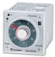
88.02.0.230.0002
Analogue Timer, Plug In, 88 Series, Multifunction, 16 Ranges, 0.05 s, 100 h, 2 Changeover Relays
⚠️ Reference pricing provided. In case of supply shortages, we will connect you with our trusted procurement partners to ensure your project's continuity.
- Manufacturer: FINDER
- Product type: Analogue Timers
- Product Range:88 Series; Timer Functions:Multifunction; No. of Timing Ranges:16Ranges; Time Min:0.05s; Time Max:100h; Timer Output:2 Changeover Relays; Supply Voltage Max:230V; Current Rating Nom:500
- SVHC: No SVHC (04-Feb-2026)
- Time Max: 100h
- Time Min: 0.05s
- Timer Output: 2 Changeover Relays
- Product Range: 88 Series
- Timer Functions: Multifunction
- Current Rating Nom: 500mA
- Panel Cutout Width: 45mm
- Supply Voltage Max: 230V
- Panel Cutout Height: 45mm
- No. of Timing Ranges: 16Ranges
- Connection / Termination: Plug-In
| Delivery and price | |
|---|---|
| Units per pack | 10 |
| Price | 73.53 € |
| Current stock | 10+ |
| Lead time | 30 days |
Datasheet

## Plug-in timers 8 A

Drying kilns Industrial furnaces and ovens Industrial washing machines Hoists and cranes Woodprocessing machines Medical and dentistry

**88 SЕRIES**

FINDER reserves the right to alter characteristics at any time without notice. FINDER assumes no liability for damage to persons or property, caused as a result of the incorrect use or application of its products.

**88 SERIES**

**H**

## **Multi-voltage and multi-function timer range Front panel or socket mount**

## **88.02**

## **88.12**

- 8 and 11 pin plug-in versions available

- Time scales from 0.05 s to 100 h

- “1 delayed contact +1 instantaneous contact” version available (type 88.12)

- Front panel mounting fixing included

- 90 series sockets

- Multi-function

- 11 pin

- Plug-in for use with 90 series sockets

- Multi-function

- 8 pin, 2 timed contacts or

- 1 timed + 1 instantaneous contact

- Plug-in for use with 90 series sockets

**AI:** On-delay

**DI:** Interval

**GI:** Pulse delayed

- **SP:** Symmetrical flasher (starting pulse off) without control signal

**Al a:** On-delay (2 timed contacts)

**Al b:** On-delay (1 timed + 1 instantaneous contact)

**Dl a:** Interval (2 timed contacts)

**Dl b:** Interval (1 timed + 1 instantaneous contact)

**GI:** Pulse delayed

**SW:** Symmetrical flasher (starting pulse on)

## without control signal

**BE:** Off-delay with control signal

**CEa:** On- and off-delay with control signal

**DE:** Interval with control signal on

with control signal

P = Pause S = Start R = Reset

|||||||vary|P = Pause||
|---|---|---|---|---|---|---|---|---|
||For outline drawing see page 5||||PS|R|P = Pause<br>S = Start||
||||Lit|~~yy ~~|N~~H~~||R = Reset||
||**Contact specification**<br>Contact configuration|||||2 CO (DPDT)||2 CO (DPDT)|
||Rated current/Maximum peak current<br>A<br>Rated voltage/<br>Maximum switchingvoltage<br>V AC|||||8/15<br>250/400||8/15<br>250/400|
||Rated load AC1|VA||||2000||2000|
||Rated load AC15 (230 V AC)|VA||||400||400|
||Single phase motor rating (230 V AC)|Single phase motor rating (230 V AC)<br>kW||||0.3||0.3|
||Breaking capacity DC1: 30/110/220 V<br>A|||||8/0.3/0.12||8/0.3/0.12|
||Minimum switching load|mW (V/mA)||||300 (5/5)||300 (5/5)|
||Standard contact material<br>**Supply specification**<br>Nominal voltage (UN)|V AC (50/60 Hz)||||AgNi<br>24…230||AgNi<br>24…230|
|||V DC||||24…230||24…230|
||Rated power AC/DC|VA (50 Hz)/W|||2.5 (230 V)/1 (24 V)|2.5 (230 V)/1 (24 V)||2.5 (230 V)/1.5 (24 V)|
||Operating range|V AC||||20.4…264.5||20.4…264.5|
||**Technical data**|V DC||||20.4…264.5||20.4…264.5|
||Specified time range|||||(0.05 s…5 h) - (0.05 s…10 h) - (0.05 s…50 h) - (0.05 s…100 h)|||
||Repeatability|%||||± 1||± 1|
||Recovery time|ms||||300||200|
||Minimum control impulse|ms||||50||—|
|XI-2018,www.findernet.com|Setting accuracy-full range<br>Electrical life at rated load AC1<br>Ambient temperature range<br>Protection category<br>**Approvals**(according to type)|%<br>cycles<br>°C||||± 3<br>100 · 103<br>–10…+55<br>IP 40|± 3<br>100 · 103<br>–10…+55<br>IP 40<br>®<br>Cé€ FAL Adis||


**3**

**88 SERIES**

## **Multi-voltage and mono-function timer range Front panel or socket mount**

**==> picture [55 x 7] intentionally omitted <==**

**----- Start of picture text -----**<br>
88.92 - 0000<br>**----- End of picture text -----**<br>


**==> picture [55 x 7] intentionally omitted <==**

**----- Start of picture text -----**<br>
88.92 - 0001<br>**----- End of picture text -----**<br>


- Asymmetrical flasher The ON and OFF time are independently adjustable

- 8 pin plug-in

- Time scales from 0.05 s to 300 h

- 2 contacts

- Front panel mounting fixing included

- 90 series sockets

- Mono-function

- 8 pin, 2 timed contacts

- Plug-in for use with 90 series sockets

**PI:** Asymmetrical flasher (starting pulse OFF)

- Mono-function

- 8 pin, 2 timed contacts

- Plug-in for use with 90 series sockets

**LI:** Asymmetrical flasher (starting pulse ON)

|**Multi-voltage and mono-function timer range**<br>**Front panel or socket mount**<br>• Asymmetrical flasher The ON and OFF time areAsymmetrical flasher The ON and OFF time are<br>independently adjustable<br>• 8 pin plug-in8 pin plug-in<br>• Time scales from 0.05 s to 300 hTime scales from 0.05 s to 300 h<br>• 2 contacts2 contacts<br>• Front panel mounting fixing includedFront panel mounting fixing included<br>• 90 series sockets90 series sockets<br>For outline drawing see page 5<br>**Contact specification**<br>Contact configuration|**88.92 - 0000**<br>• Mono-functionMono-function<br>• 8 pin, 2 timed contacts8 pin, 2 timed contacts<br>• Plug-in for use with 90 series socketsPlug-in for use with 90 series socketsg-in for use with 90 series sockets-in for use with 90 series sockets<br>aoe<br>“|**88.92 - 0001**<br>• Mono-functionMono-function<br>• 8 pin, 2 timed contacts8 pin, 2 timed contacts<br>• Plug-in for use with 90 series socketsPlug-in for use with 90 series socketsg-in for use with 90 series sockets-in for use with 90 series sockets<br>aoe<br>¥|**88.92 - 0001**<br>• Mono-functionMono-function<br>• 8 pin, 2 timed contacts8 pin, 2 timed contacts<br>• Plug-in for use with 90 series socketsPlug-in for use with 90 series socketsg-in for use with 90 series sockets-in for use with 90 series sockets<br>aoe<br>¥|**88.92 - 0001**<br>• Mono-functionMono-function<br>• 8 pin, 2 timed contacts8 pin, 2 timed contacts<br>• Plug-in for use with 90 series socketsPlug-in for use with 90 series socketsg-in for use with 90 series sockets-in for use with 90 series sockets<br>aoe<br>¥|
|---|---|---|---|---|
||**PI:**Asymmetrical flasher (starting pulse OFF)<br>without control signal<br>2 CO (DPDT)<br>A1JA2}12 |11]14 |22]21| 24<br>21/714/1/3/5/8<br>16<br>/<br>[7]<br>L)<br>Ci<br>C2<br>UX|**LI:**Asymmetrical flasher (starting pulse ON)<br>without control signal<br>2 CO (DPDT)<br>A1JA2}12<br>|11 114 |22 |21) 24<br>2/7/4/1/3/5/8<br>1/6<br>/<br>|<br>|)<br>C1<br>C2<br>Ux|||
|Rated current/Maximum peak current<br>A|8/15|8/15|||
|Rated voltage/<br>Maximum switchingvoltage<br>V AC|250/400|250/400|||
|Rated load AC1<br>VA|2000|2000|||
|Rated load AC15 (230 V AC)<br>VA|400|400|||
|Single phase motor rating (230 V AC)<br>kW|0.3|0.3|||
|Breaking capacity DC1: 30/110/220 V<br>A|8/0.3/0.12|8/0.3/0.12|||
|Minimum switching load<br>mW (V/mA)|300 (5/5)|300 (5/5)|||
|Standard contact material<br>**Supply specification**<br>Nominal voltage (UN)<br>V AC (50/60 Hz)<br>V DC|AgNi<br>12…240|AgNi<br>12…240|||
||12…240|12…240|||
|Rated power AC/DC<br>VA (50 Hz)/W|2.5 (230 V)/1.5 (24 V)|2.5 (230 V)/1.5 (24 V)|||
|Operating range<br>V AC<br>V DC<br>**Technical data**<br>Specified time range|10.8…264.5|10.8…264.5|||
||10.8…264.5<br>See “Time Scale” page 3|10.8…264.5<br>See “Time Scale” page 3|||
|Repeatability<br>%|± 1|± 1|||
|Recovery time<br>ms|200|200|||
|Minimum control impulse<br>ms|—|—|||
|Setting accuracy-full range<br>%|± 1|± 1|||
|Electrical life at rated load AC1<br>cycles|100 · 103|100 · 103|||
|Ambient temperature range<br>°C|–10…+55|–10…+55|||
|Protection category|IP 40|IP 40|||
|**Approvals**(according to type)|||||


**4**

**88 SERIES**

**H**

## **Ordering information**

Example:  88 series multi-function timer, 2 CO (DPDT) 8 A contacts, (24…230)V AC (50/60 Hz) and (24…230)V DC supply.

**8 8 . 0 2 . 0 . 2 3 0 . 0 0 0 2**

## **Series**

## **Type**

- 0 =  Functions AI, DI, GI, SP, BE, CEa, DE, 11 pin

- 1 =  Functions Al a, Al b, Dl a, Dl b, GI, SW, 8 pin

9 =  Functions LI, PI, 8 pin

**No. of poles** 2 =  2 pole

## **Supply version**

0 =  AC (50/60 Hz)/DC

## **Special versions**

0 =  Functions PI (starting pulse OFF) for 88.92

- 1 =  Functions LI (starting pulse ON) for 88.92

2 =  Standard

## **Supply voltage**

230 =  (24…230)V AC/DC for 88.02, 88.12 240 =  (12…240)V AC/DC for 88.92

## **Codes**

88.02.0.230.0002

88.12.0.230.0002

88.92.0.240.0000 88.92.0.240.0001

## **Technical data**

## **EMC specifications**

|**Type of test**||**Reference standa**|**rd**<br>**88.02/88.12**|**88.92**|
|---|---|---|---|---|
|Electrostatic discharge|contact discharge|EN 61000-4-2|4 kV|4 kV|
||air discharge|EN 61000-4-2|8 kV|6 kV|
|Radio-frequencyelectromagnetic field (80 ÷ 1000 MHz)||EN 61000-4-3|10 V/m|10 V/m|
|Fast transients (burst) (5-50 ns, 5 kHz) on Supplyterminals||EN 61000-4-4|2 kV|—|
|Surges (1.2/50 μs) on Supply terminals|common mode|EN 61000-4-5|2 kV|—|
||differential mode|EN 61000-4-5|1 kV|—|
|Radio-frequency common mode (0.15 ÷ 80 MHz) on Supply terminals||EN 61000-4-6|3 V|—|
|**Other data**|||||
|Power lost to the environment|without contact current W|3.4|||
||with rated current W|4.7|||


## **Outline drawings**

Types 88.02/12

**==> picture [121 x 267] intentionally omitted <==**

Type 88.92

**==> picture [141 x 235] intentionally omitted <==**

**==> picture [42 x 34] intentionally omitted <==**

**5**

**88 SERIES**

## **Selection of: function, time scale and units**

||**88.02**|**88.12**|**88.92 - 0000**|**88.92 - 0001**|
|---|---|---|---|---|
|**Function**|AI, DI, GI, SP, BE, CEa, DE|Al a, Al b, Dl a, Dl b, GI, SW|PI|LI|
|**Time scale**|0.5, 1, 5, 10||1.2, 3, 12, 30||
|**Unit of time**|s (second), min (minute), h (hour), 10 h (10 hours)||s (second), 10 s (second x 10), min (minute),<br>10 min(minute x 10),h(hour),10 h(hour x 10)||


## **Time scales**

|**Time scales**|**Time scales**|**Time scales**|**Time scales**|||
|---|---|---|---|---|---|
|**Full scale value for types 88.02, 88.12**<br>**s**<br>**min**<br>**h**<br>**10 h**<br>A<br>B<br>C<br>D<br>**0.5**<br>0.5 second<br>0.5 minute<br>0.5 hour<br>5 hour<br>**1**<br>1 second<br>1 minute<br>1 hour<br>10 hour<br>**5**<br>5 second<br>5 minute<br>5 hour<br>50 hour<br>**10**<br>10 second<br>10 minute<br>10 hour<br>100 hour<br>**D**<br>**H**||||**Types 88**|**.02, 88.12**<br>H<br>G<br>EF|
|**D**<br>|**s**|**min**|**h**|||
|**0.5**|0.5 second|0.5 minute|0.5 hour|||
|**1**|1 second|1 minute|1 hour|||
|**5**|5 second|5 minute|5 hour|||
|**10**|10 second|10 minute|10 hour|||


## **Full scale value for type 88.92**

||||||||||
|---|---|---|---|---|---|---|---|---|
|**Full scale value for type 88.92**<br>**Type**<br>**s**<br>**10 s**<br>**min**<br>**10 min**<br>**h**<br>**10 h**<br>A<br>B<br>D<br>C<br>**1.2**<br>1.2 second<br>12 second<br>1.2 minute<br>12 minute<br>1.2 hour<br>12 hour<br>**3**<br>3 second<br>30 second<br>3 minute<br>30 minute<br>3 hour<br>30 hour<br>**12**<br>12 second<br>120 second<br>12 minute<br>120 minute<br>12 hour<br>120 hour<br><br> <br> <br> <br> <br> <br> <br>**H D-E**||||||||**88.92**<br>H<br>G<br>F<br>E|
|**1.2**|1.2 second|12 second|1.2 minute|12 minute|1.2 hour|12 hour|||
|**3**|3 second|30 second|3 minute|30 minute|3 hour|30 hour|||
|**12**<br>|12 second<br>|120 second<br>|12 minute<br>|120 minute<br>|12 hour<br>|120 hour<br>|||


NOTE: time scales and functions must be set before energising the timer.

## **LED/visual indication**

**H**

|**Types 88.02, 88.12**<br>**A**<br>Yellow LED:power ON (U)<br>**B**<br>Red LED: timinginprogress (C)<br>**C**<br>Unit of time selected<br>**D**<br>Time scale selector<br>**E**<br>Function selector<br>**F**<br>Function selected<br>**G**<br>Time scale selected<br>**H**<br>Unit of time selector|**Types 88.02, 88.12**<br>**A**<br>Yellow LED:power ON (U)<br>**B**<br>Red LED: timinginprogress (C)<br>**C**<br>Unit of time selected<br>**D**<br>Time scale selector<br>**E**<br>Function selector<br>**F**<br>Function selected<br>**G**<br>Time scale selected<br>**H**<br>Unit of time selector|**Type 88.92**|**Type 88.92**|
|---|---|---|---|
|**A**|Yellow LED:power ON (U)|**A**|Red LED:pulse ON (T1)|
|**B**|Red LED: timinginprogress (C)|**B**|Green LED:pulse OFF (T2)|
|**C**|Unit of time selected|**C**|Red timingregulator: T1 time setting|
|**D**|Time scale selector|**D**|Unit of time selector: T1 (ON)|
|**E**|Function selector|**E**|Unit of time selector: T2 (OFF)|
|**F**|Function selected|**F**|Green timingregulator: T2 time setting|
|**G**|Time scale selected|**G**|Time scale selected|
|**H**|Unit of time selector|**H**|Time scale selector|


**6**

**88 SERIES**

## **Functions for types 88.02, 88.12**

|**U**=<br>Supply<br>Voltage<br>**S**=<br>Signal<br>switch<br>**P**=<br>Pause<br>**R**=<br>Reset<br>=  Output<br>Contact<br>**Wiring diagram**||LED<br>(yellow)|LED<br>(yellow)|LED<br>(yellow)|LED<br>(yellow)|LED<br>(red)|Supply<br>voltage|NO output<br>contact|Contact<br>Open<br>Closed|Contact<br>Open<br>Closed|
|---|---|---|---|---|---|---|---|---|---|---|
||||||||OFF|Open|x1 - x4|x1 - x2|
||||||||ON|Open|x1 - x4<br>x1 - x2|x1 - x2<br>x1 - x4|
||||||||||||
||||||||||||
||||||||ON|Open (timing<br>inprogress)|x1 - x4|x1 - x2|
||||||||ON|Closed|x1 - x2|x1 - x4|
||||||||||||
||||||||||||
|||**Type 88.02**|||||||||
|without control signal||||||**(AI)** **On-delay.**|||||
||||||||||||
||||||||||||
||||||||||||


**(AI) On-delay.** Apply power to timer. Output contacts transfer after preset time has elapsed. Reset occurs when power is removed. **(DI) Interval.** Apply power to timer. Output contacts transfer immediately. After the preset time has elapsed, contacts reset. **(GI) Pulse delayed.** Apply power to timer. Output contacts transfer after preset time has elapsed. Reset occurs after a fixed time of 0.5 s.

**==> picture [273 x 72] intentionally omitted <==**

with control signal

**==> picture [155 x 45] intentionally omitted <==**

**(SP) Symmetrical flasher (starting pulse off).** Apply power to timer. First transfer of contact occurs after preset time has elapsed. The timer now cycles between OFF and ON as long as power is applied. The ratio is 1:1 (time on = time off). **(BE) Off-delay with control signal.** Power is permanently applied to the timer. The output contacts transfer immediately on closure of the Signal **H** Switch (S). Opening the Signal Switch initiates the preset delay, after which time the output contacts reset. **(CEa) On- and off-delay with control signal.** Power is permanently applied to the timer. Closing the Signal Switch (S) initiates the preset delay, after which time the output contacts transfer. Opening the Signal switch initiates the same preset delay, after which time the output contacts reset.

**(DE) Interval with control signal on.** Power is permanently applied to the timer. On momentary or maintained closure of Signal Switch (S), the output contacts transfer, and remain so for the duration of the preset delay, after which they reset.

## **RESET (R)**

A momentary closure of the reset switch (2-7) will reset the timer. Longer term closure of the reset switch will hold the timer in the reset state. This is applicable for all functions.

## **PAUSE (P)**

Closure of the pause switch (2-5) will immediately halt the timing process, but the elapsed time will be retained, and the current state of the output contacts will be maintained.

On opening of the pause switch, timing resumes from the retained value. This is applicable for all functions.

**7**

**88 SERIES**

## **Functions for type 88.12**

## **Wiring diagram Type 88.12**

> without control signal **(Al a) On-delay (2 timed contacts).** Apply power to timer. Contacts (C1 and C2) transfer after preset time has elasped. Reset occurs when power is removed. **(Al b) On-delay (1 timed contact + 1 instantaneous contact).** Apply power to timer. Output contact (C1) transfers immediately. Contact (C2) transfers after the preset time has elasped. Reset occurs when power is removed. **(Dl a) Interval (2 timed contacts).** Apply power to timer. Output contacts (C1 and C2) transfer immediately. After preset time has elasped, the contacts reset. **(Dl b) Interval (1 timed contact + 1 instantaneous contact).** Apply powert to timer. Output contacts (C1 and C2) transfer immediately. After preset time has elasped, the contact (C2) resets. Contact (C1) resets when power is removed.

## **H**

**==> picture [151 x 45] intentionally omitted <==**

**==> picture [165 x 44] intentionally omitted <==**

**(GI) Pulse delayed.** Apply power to timer. Output contacts transfer after preset time has elapsed. Reset occurs after a fixed time of 0.5 s. **(SW) Symmetrical flasher (starting pulse on).** Apply power to timer. Output contacts transfer immediately and cycle between ON and OFF for as long as power is applied. The ratio is 1:1 (time on = time off).

## **Functions for type 88.92**

|**U**=<br>Supply<br>Voltage<br>**Wiring diagram**||LED ON<br>(red)|LED OFF<br>(green)|Supply<br>voltage|Contact<br>Open<br>Closed|Contact<br>Open<br>Closed|
|---|---|---|---|---|---|---|
|||||OFF|11 - 14<br>21 - 24|11 - 12<br>21 - 22|
|||||ON|11 - 12<br>21 - 22|11 - 14<br>21 - 24|
|||||ON|11 - 14<br>21 - 24|11 - 12<br>21 - 22|
|||**Type 88.92**|||||


## without control signal

**(LI) Asymmetrical flasher (starting pulse ON).**

Apply power to timer. Output contacts transfer immediately and cycle between ON and OFF for as long as power is applied. The ON and OFF times are independently adjustable.

## **(PI) Asymmetrical flasher (starting pulse OFF).**

Apply power to timer. Output contacts transfer after time T2 has elapsed and cycle between OFF and ON for as long as power is applied. The ON and OFF times are independently adjustable.

**8**

**88 SERIES**

**==> picture [424 x 649] intentionally omitted <==**

**----- Start of picture text -----**<br>
||||||||||||||||
|---|---|---|---|---|---|---|---|---|---|---|---|---|---|---|
|Screw terminal (Box clamp) socket|90.20|90.20.0|90.21|90.21.0|
|panel or 35 mm rail (EN 60715) mount|Blue|Black|Blue|Black|
|For timer type|88.12, 88.92|88.02|
|Technical data|
|Rated values|10 A - 250 V|
|Dielectric strength|2 kV AC|
|Protection category|IP 20|
|Ambient temperature|°C|–40…+70|
|SG|Screw torque|Nm|0.5|
|Wire strip length|mm|10|
|Max. wire size for 90.20 and 90.21 sockets|solid wire|stranded wire|
|mm|[2]|1 x 6 / 2 x 2.5|1 x 6 / 2 x 2.5|
|AWG|1 x 10 / 2 x 14|1 x 10 / 2 x 14|
|NO|NC|NC|NO|elena@2|NO NC NO NC NO NC|Renewsa®626@|=|
|[oxe)|0°00|
|©|8|11.O-cooOoO ogloO|&||&|O|C|rn}®|f1.oOO)|OOgo°oOoo, S||F|8|fo ||
|[|||a|e|tL|s|x|f|
|a|wD,|Gl|iD,|
|7}|La}|1}|12|haa|38|10)|La}|Le}|L}|Lz|a|38|=25.5|
|COIL COM|COM|COIL|COIL|COMCOMCOM|COIL|
|90.20|90.21|
|Screw terminal (Box clamp) socket|90.26|90.26.0|90.27|90.27.0|
|panel or 35 mm rail (EN 60715) mount|Blue|Black|Blue|Black|
|For timer type|88.12, 88.92|88.02|
|Technical data|
|Rated values|10 A - 250 V|
|Dielectric strength|2 kV AC|
|Protection category|IP 20|
|Ambient temperature|°C|–40…+70|
|Screw torque|Nm|PO|0.8|
|Wire strip length|mm|10|
|Max. wire size for 90.26 and 90.27 sockets|solid wire|stranded wire|
|mm|[2]|1 x 4 / 2 x 2.5|1 x 4 / 2 x 2.5|
|AWG|1 x 12 / 2 x 14|1 x 12 / 2 x 14|
|NO6SNC|NCI4|NOI3|oo——|Nao||a|aan|fo|||NC8IL7NOCOM6|NCa5|—jejejeje]|—|«Ss|CT“A|
|-||oe 25|a|n|hi|229|(@)|We-|
|O|||o> ae”=|| &|O|ice)8|DoOs|ee|1|y|8||ae|||
|6|a|Bi|g|
|COILCOMCOMCOIL|a41|||“efio«23fe|23|,|||COIL|i|CO|MCOM|COI|mL|,{@lelele]|“) 4Aim31|e|
|90.26|90|.|27|
|Sockets 8-11 pin backwired with solder terminals|90.12.4 (black)|90.13.4 (black)|
|For timer type|88.12, 88.92|88.02|
|Technical data|
|Rated values|10 A - 250 V|
|Dielectric strength|2 kV AC|
|Ambient temperature|°C|–40…+70|

**----- End of picture text -----**<br>


**90.21** Approvals (according to type):

**==> picture [96 x 58] intentionally omitted <==**

**----- Start of picture text -----**<br>
90.26<br>Approvals<br>(according to type):<br>CCE S® OG<br>**----- End of picture text -----**<br>


**==> picture [66 x 35] intentionally omitted <==**

**----- Start of picture text -----**<br>
90.13.4<br>Approvals<br>(according to type):<br>**----- End of picture text -----**<br>


## **H**

Please see general technical information

**9**
Updated at April 29, 2026
About Novapart
Novapart is a B2B electronic component broker specialising in stock shortages and cost reduction. We source hard-to-find parts and identify compliant alternatives across a catalogue of 410,000+ components from 500+ manufacturers.
Learn more →Stock Shortage Specialist
When a component is unavailable, discontinued or has an unacceptable lead time, we tap into our network of vetted European and Asian distributors to source what you need — without compromising on quality or traceability.
Request a quote →Compliant Alternatives
We identify pin-to-pin, electrically equivalent substitutes that meet the same certifications (RoHS, AEC-Q100, REACH) as your original specification — validated against datasheets, not just part numbers. Often at a lower cost.
BOM Analysis service →