
Image not available
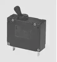
Illustrative purposes only

8340-F410-P1M2-A2H0-10A
Magnetic Hydraulic Circuit Breaker, 8340 Series, 10 A, 1 Pole, 2 kA
⚠️ Reference pricing provided. In case of supply shortages, we will connect you with our trusted procurement partners to ensure your project's continuity.
- Manufacturer: ETA
- Product type: Magnetic Hydraulic Circuit Breakers
- Product Range:8340 Series; Current Rating:10A; No. of Poles:1 Pole; Input Voltage VAC:-; Interrupting Capacity:2kA; Trip Time:-; Dielectric Strength:-; SVHC:No SVHC (15-Jan-2018); App
- Trip Time: -
- No. of Poles: 1 Pole
- Product Range: 8340 Series
- Current Rating: 10A
- Input Voltage VAC: -
- Dielectric Strength: -
- Interrupting Capacity: 2kA
| Delivery and price | |
|---|---|
| Units per pack | 20 |
| Price | 55.89 € |
| Current stock | 10+ |
| Lead time | 30 days |
Datasheet

**Magnetic and Hydraulic-Magnetic Circuit Breaker 8340-F...**

**4**

## **Description**

Single and multipole magnetic circuit breakers with trip-free mechanism and toggle actuation. A choice of fast magnetic only or hydraulically delayed switching characteristics (S-type MO or HM CBE to EN 60934) ensures suitability for a wide range of applications. Industry standard dimensions and panel mounting. Options include auxiliary changeover contacts. Low temperature sensitivity at rated load.

Approved to CBE standard EN 60934 (IEC 60934).

## **Typical application** ~~Lo~~

Control equipment, communications systems, transportation, power supplies.

**==> picture [149 x 18] intentionally omitted <==**

**----- Start of picture text -----**<br>
8340-F...<br>      1-pole                                     2-pole<br>**----- End of picture text -----**<br>


## **Standard current ratings and typical internal resistance values**

## **Technical data**

||**For further detailsplease see chapter: Technical Information**|
|---|---|
|Voltage rating                  3 AC 415 V; AC 240 V, 50/60 Hz; DC 80 V<br>(higher DC ratings to special order)<br>Current ratings<br>0.02...50 A single pole (40+50 A DC only)<br>0.02...30 A multipole<br>Auxiliary circuit<br>6 A, AC 240 V;<br>3 A, DC 28 V<br>1 A, DC 65 V;<br>0.5 A,DC 80 V<br>Typical life<br>3 AC 415 V, AC 240 V:<br>0.02...30 A<br>6,000 operations at 1 x IN, inductive<br>10,000 operations at 1 x IN, resistive<br>DC 80 V: 0.02...25 A<br>6,000 operations at 1 x IN, inductive<br>0.02...30 A<br>10,000 operations at 1 x IN, resistive<br>40 + 50 A<br>6,000 operations at 1 x IN,resistive<br>Ambient temperature          -40...+85 °C(-40...+185 °F)<br>Insulation co-ordination      rated impulse<br>pollution<br>(IEC 60664 and 60664A)<br>withstand voltage<br>degree<br>2.5 kV<br>2<br>reinforced insulation in operatingarea<br>Dielectric strength<br>(IEC 60664 and 60664A)<br>test voltage<br>operating area<br>AC 3,000 V<br>pole to pole(2- and 3-pole)<br>AC 1,500 V<br>main to auxiliary circuit<br>AC 3,000 V<br>switchingto tripcircuit<br>AC 1,500 V(version -X)<br>Insulation resistance           > 100 MΩ(DC 500 V)<br>Interrupting capacity<br>6 x IN at AC;<br>IEC 60934 - test sequence E 4 x IN at DC<br>Interrupting capacity<br>IN<br>0.02...20 A<br>25...30 A<br>(UL 1077)<br>AC:<br>1-pole<br>AC 250 V/3,500A<br>AC 250 V/3,500A<br>2-pole<br>AC 250 V/3,500A   AC 250 V/5,000A<br>3-pole  3AC 250V/3,500A   3AC250V/5,000A<br>DC:<br>1-pole   0.02...50 A<br>DC 80 V/3,500 A<br>**M2, T2**<br>2457<br>376<br>94<br>14.7<br>3.2<br>1.56<br>0.90<br>0.20<br>0.15<br>0.10<br>0.040<br>0.028<br>< 0.02<br>< 0.02<br>< 0.02<br>< 0.02<br>< 0.02<br>< 0.02<br>< 0.02<br>< 0.02<br>-<br>-<br>~~ee~~<br>~~ee~~<br>~~Pf A~~<br>~~____~~<br>~~ee~~<br>~~ee~~<br>~~Ce~~<br>~~ee~~<br>~~ee~~<br>~~ee~~<br>~~ee~~<br>~~DD (open~~<br>~~ee~~<br>~~ee~~<br>~~Sr~~<br>~~ee~~<br>~~ee~~<br>~~ee~~<br>~~| Sa~~<br>~~ee~~<br>~~Oe~~<br>~~ee~~<br>~~ee~~<br>~~re~~||
||2-pole<br>0.02...30 A<br>DC 80 V/3500 A|
||Degree of protection           operating area IP40|
||(IEC 60529/DIN 40050)terminal area IP00|
||Vibration|
||with toggle down:<br>10 g (57-2000Hz) ± 0.76 mm (10-57 Hz)|
||at 0.9 x IN|
||directions 1,2,3,4,5:  10g (57-2000 Hz)at 1 x IN.|
||Shock<br>100 g (11 ms) at 1 x IN, directions 1,2,3,4,5|
||100g (11 ms)at 0.8 x IN,direction 6.|
||Corrosion                           96 hours at 5 % salt mist,|
||to IEC 60068-2-11,test Ka|
||Humidity<br>240 hours at 95 % RH|
||to IEC 60068-2-78,test Cab|
||Mass                                 approx. 65g perpole|


|**Current rating (A)**|~~ee~~|~~ee~~|
|---|---|---|
|~~ee~~<br>~~ee~~|**K1, M1, T1,**<br>~~ee~~<br>~~ee~~<br>~~ee~~<br>~~ee~~|**M2, T2**<br>~~ee~~<br>~~ee~~|
|0.02<br>~~ee~~<br>~~Pf~~|2669<br>~~ee~~<br>~~ee~~<br>~~ee~~<br>~~Pf~~|2457<br>~~ee~~<br>~~Pf~~|
|0.05<br>~~Pf~~|452<br>~~ee~~<br>~~Pf~~<br>~~ee~~|376<br>~~Pf~~|
|0.1<br>~~Pf~~<br>~~ee~~|100<br>~~Pf~~<br>~~ee~~<br>~~ee~~<br>~~ee~~|94<br>~~Pf ~~<br>~~ee~~|
|0.25<br>~~ee~~|15.5<br>~~ee~~<br>~~ee~~<br>~~ee~~|14.7<br>~~ee~~|
|0.5<br>~~ee~~<br>~~C~~|3.9<br>~~ee~~<br>~~ee~~<br>~~C~~<br>~~ee~~|3.2<br>~~ee~~<br>~~C~~|
|0.75<br>~~ee~~|1.65<br>~~ee~~<br>~~ee~~<br>~~ee~~|1.56<br>~~ee~~|
|1<br>~~ee~~<br>~~ee~~|0.95<br>~~ee~~<br>~~ee~~<br>~~ee~~<br>~~ee~~<br>~~ee~~|0.90<br>~~ee~~<br>~~ee~~|
|2<br>~~ee~~|0.26<br>~~ee~~<br>~~ee~~<br>~~ee~~<br>~~es~~|0.20<br>~~ee~~|
|2.5<br>~~ee~~<br>~~ee~~|0.15<br>~~ee~~<br>~~ee~~<br>~~ee~~<br>~~es~~|0.15<br>~~ee~~<br>~~ee~~|
|3<br>~~DD~~|0.10<br>~~es~~<br>~~DD~~|0.10<br>~~DD~~|
|5<br>~~DD~~<br>~~ee~~|0.042<br>~~DD~~<br>~~ee~~<br>~~es~~<br>~~ee~~|0.040<br>~~DD ~~<br>~~ee~~|
|6<br>~~ee~~|0.029<br>~~es~~<br>~~ee~~<br>~~ee~~|0.028<br>~~ee~~|
|8<br>~~S~~|< 0.02<br>~~ee~~<br>~~S~~<br>~~ee~~|< 0.02<br>~~S~~|
|10<br>~~ee~~|< 0.02<br>~~ee~~<br>~~ee~~<br>~~ee~~|< 0.02<br>~~ee~~|
|12<br>~~ee~~|< 0.02<br>~~ee~~<br>~~ee~~<br>~~ee~~<br>~~ee~~|< 0.02<br>~~ee~~|
|15<br>~~ee~~<br>~~ee~~|< 0.02<br>~~ee~~<br>~~ee~~<br>~~ee~~<br>~~ee~~|< 0.02<br>~~ee~~<br>~~ee~~|
|16<br>~~|~~|< 0.02<br>~~ee~~<br>~~|~~|< 0.02<br>~~| Sa~~|
|20<br>~~|~~<br>~~ee~~<br>~~es~~|< 0.02<br>~~|~~<br>~~ee~~|< 0.02<br>~~| Sa~~<br>~~ee~~<br>~~O~~|
|25<br>~~es~~|< 0.02<br>~~ee~~|< 0.02<br>~~O~~|
|30<br>~~es~~<br>~~ee~~<br>~~ee~~|< 0.02<br>~~ee~~<br>~~ee~~<br>~~**ee**~~|< 0.02<br>~~O~~<br>~~ee~~|
|40<br>~~ee~~<br>~~ee~~|≤ 0.01<br>~~ee~~<br>~~ee~~<br>~~**ee**~~|-<br>~~ee~~|
|50<br>~~ee~~<br>~~ee~~|≤ 0.01<br>~~ee~~<br>~~**ee**~~|-<br>~~ee~~|


**www.e-t-a.de**

Issue D

**4** - 13

**Magnetic and Hydraulic-Magnetic Circuit Breaker 8340-F...**

**4**

## **Ordering information**

**Type No.**

**8340** magnetic circuit breaker with toggle actuator

**Mounting**

- **F** flange mounting

**Configuration**

- **4** with mounting nuts M3

- **9** snap-in frame

   - **Number of poles**

   - **1** single pole protected

   - **2** two pole protected

   - **3** three pole protected

      - **Panel hardware**

      - **0** without panel hardware

         - **Terminal design (main contact)**

## **Homologations**

|**Authority**|**Voltage ratings**|**Current ratings**|
|---|---|---|
|VDE<br>(EN 60934)|3 AC 415 V; AC 240 V;<br>DC 80 V|0.02...30 A 1 to 6-pole|
||DC 80 V|0.02...50 A 1-pole|
|UL 1077, CSA|DC 80 V|0.02...50 A 1 to 6-pole|
||3 AC 250 V; AC 250 V|0.02...30 A 1 to 6-pole|
|QPL (Sweden)|AC 240 V; DC 50 V|1...30 A|
|CCC|3 AC 415 V; AC 240 V|0.02...30 A|
||DC 80 V|0.02...50 A 1, 2-pole|


- **K4** screw terminals with metric thread, M5 (I ~~N~~ = 20 A)

- **P1** blade terminals

**Characteristic curve Characteristic curve K, short delay: K1** DC  trip time at 2 x I ~~N~~ : 0.16-1.2 s **Characteristic curve M, medium delay: M1** DC  trip time at 2 x I ~~N~~ : 0.6-7.5 s **M2** AC 60/50Hz trip time at 2 x I ~~N~~ : 2.2-20 s **Characteristic curve T, long delay: T1** DC  trip time at 2 x I ~~N~~ : 10-70 s **T2** AC 60/50Hz trip time at 2 x I ~~N~~ : 15-150 s

|**Actuator colour/design**|**Actuator colour/design**|
|---|---|
|**A**black, long toggle||
|**K**black, short toggle||
|**Z**black, without toggle, with slot||
|**other colours to special order**||
|**Marking on actuator**||
|**0**without marking<br>**L**I-O; ON-OFF||
|**N**I-O; ON-OFF (IN on housing top)||
|**Auxiliary contacts**||
|**H0** without|auxiliary contacts|
|**H1**with auxiliary contacts, gold-flushed||
|**H2**auxiliary contacts, gold-flushed||
|on one pole only (multipole)||
|**Auxiliary contact function**||
|**4**1 change over contact||
|**Auxiliary contact terminal design**||
|**2**<br>blade terminal 2.8-0.5 mm||
|**Current ratings**||
|0.02...50 A||
|||


## **Internal connection diagrams**

**==> picture [249 x 177] intentionally omitted <==**

**----- Start of picture text -----**<br>
1-pole protected multipole<br>magnetic line  1 11(C)<br>line 1 11(C) unit 1<br>12(NC) 14(NO)<br>12(NC) 14(NO) I ><br>I > 2<br>1 11(C)<br>2 load<br>1-pole protected unit 2<br>hydraulic-magnetic<br>12(NC) 14(NO)<br>line  1 11(C)<br>I ><br>2 load<br>unit 3<br>12(NC) 14(NO)<br>I ><br>2 load<br>**----- End of picture text -----**<br>


**8340 - F 1 1 0 -  P1  M1 - A L  H1 4  2  - 30A** ordering example

|||||||||||||||
|---|---|---|---|---|---|---|---|---|---|---|---|---|---|
|**Preferred types**<br>W<br>E<br>N||||||||||||||
|||||||||||||||
|**Preferred types**|**Standard current ratings (A)**|||||||||||||
||**1**|**2**|**3**|**5**|**8**|**10**|**12**|**16**|**20**|**25**|**30**|**40**|**50**|
|8340-F410-P1K1-ALH0-|x|x|x|x|x|x|x|x|x|||||
|8340-F410-P1K1-ALH142-|x|x|x|x|x|x|x|x|x|||||
|8340-F410-P1M1-ALH0-|x|x|x|x|x|x|x|x|x|||||
|8340-F410-P1M1-ALH142-|x|x|x|x|x|x|x|x|x|||||
|8340-F410-K4K1-ALH0-||||||||||x|x|x|x|
|8340-F410-K4K1-ALH142-||||||||||x|x|x|x|
|8340-F410-K4M1-ALH0-||||||||||x|x|x|x|
|8340-F410-K4M1-ALH142-||||||||||x|x|x|x|


**www.e-t-a.de**

Issue D

**4** - 14

**4**

## **Magnetic and Hydraulic-Magnetic Circuit Breaker 8340-F...**

## **Dimensions**

**==> picture [249 x 692] intentionally omitted <==**

**----- Start of picture text -----**<br>
Flange mounting<br>Configuration: F4<br>Actuator: long toggle<br>5.5<br>.217<br>ON OFF<br>1 4 3 2<br>50.8 19<br>2.00 .748<br>26.7 4.3<br>1.05 .169<br>42.2<br>1.66<br>Actuator: short toggle<br>5.5<br>ON OFF .217<br>1 4 3 2<br>Actuator: without toggle, with slot<br>ON OFF<br>1 4 3 2<br>Applicable for nominal dimensions without direct tolerance indication:<br>DIN ISO 286 ± IT13<br>number of poles: 1-3<br>pole: 1 2 3<br>19<br>mounting thread M3<br>.748 or 6-32 UNC-2B<br>mounting depth<br>max. 4.5 mm/.177 in.<br>Cut-out dimensions tightening torque max. 0.33 Nm<br>max. panel thickness: 3 mm<br>43.5+0.1-0.15 [±0.1][(6-32UNC)]  (M3)<br>.138 [±.004]  (M3)<br>.157+.004-.006 [(6-32UNC)]<br>19.05 [±0.12]<br>.750 [±.005] 38.1 [±0.12]<br>1.50 [±.005]<br>30°<br>30°<br>30°<br>30°<br>30° 30°<br>3.3 .130<br>17.5 .689<br>41.2 1.62<br>Ø15 .591<br>8.6 .339<br>3.3 .130<br>3.3 .130<br>5.3 .208<br>±0.12 ±.004<br>Ø16 .630<br>±0.1 ±.004<br>26.7 1.05<br>±0.1 ±.004<br>42.2 1.66<br>**----- End of picture text -----**<br>


**==> picture [249 x 643] intentionally omitted <==**

**----- Start of picture text -----**<br>
Configuration: F9<br>Actuator: long toggle<br>ON OFF<br>1 4 3 2<br>50.8<br>2.00<br>66<br>2.60<br>27.4<br>1.08<br>Actuator: short toggle<br>ON OFF<br>Actuator: without toggle, with slot<br>ON OFF<br>number of poles: 1-3<br>Pole 1 2 3<br>Cut-out dimensions<br>max. panel thickness:  2 ± 0.1 mm or 4 ± 0.15 mm<br>(snap-fit)<br>57.6 [±0.2]<br>2.27 [±.008]<br>38.4 [±0.2]<br>1.51 [±.008]<br>19.2 [±0.2]<br>.756 [±.008]<br>Applicable for nominal dimensions without direct tolerance indication:<br>DIN ISO 286 ± IT13<br>30°  30°<br>30°<br>30°<br>30°<br>30°<br>14.4 .567<br>3<br>.118<br>41.2 1.62<br>19 .748<br>5.6 .220<br>±0.2 ±.008<br>55.4 2.18<br>**----- End of picture text -----**<br>


This is a metric design and millimeter dimensions take precedence ~~(~~[mm ] inch ~~)~~

**www.e-t-a.de**

Issue D

**4** - 15

**Magnetic and Hydraulic-Magnetic Circuit Breaker 8340-F...**

**4**

## **Terminal design / Dimensions**

**==> picture [249 x 367] intentionally omitted <==**

**----- Start of picture text -----**<br>
K4   screw terminals K4 screw terminals M5<br>tightening torque max. 1.2 Nm<br>1<br>1 4 3 2<br>6 38.8 9.4<br>.236 1.53 .370<br>P1   blade terminals<br>1 4 3 2<br>6 38.8 blade terminals<br>.236 1.53 DIN 46244-A6.3-0.8<br>Auxiliary contacts<br>version H (standard, asymmetrical gold-flushed terminals,<br>silver contacts<br>1 2<br>11 14 12<br>17.9 10.2<br>.705 .401<br>5.1 blade terminals<br>.200 DIN 46244-A2.8-0.5<br>9.7 .382<br>9.6 .378<br>14.5 .571<br>5<br>.197<br>**----- End of picture text -----**<br>


## **Actuator configuration**

**==> picture [134 x 265] intentionally omitted <==**

**----- Start of picture text -----**<br>
Actuator design<br>number of poles: 1 - 3<br>Configuration: F4<br>Actuator long<br>OFF0 OFF0 OFF0 OFF0 OFF0 OFF0<br>16 A 16 A 16 A<br>Actuator short<br>OFF0 OFF0<br>16 A<br>16 A<br>number of poles: 1 - 3<br>Configuration: F9<br>Actuator long<br>OFF0 OFF0 OFF0 OFF0 OFF0 OFF0<br>16 A 16 A 16 A 16 A 16 A 16 A<br>**----- End of picture text -----**<br>


**==> picture [158 x 91] intentionally omitted <==**

**----- Start of picture text -----**<br>
number of poles: 1<br>Configuration: F4 / F9<br>Actuator: Z  (black, without toggle, with slot)<br>OFF OFF<br>16 A<br>16 A<br>**----- End of picture text -----**<br>


## **Installation drawing**

**==> picture [211 x 195] intentionally omitted <==**

**----- Start of picture text -----**<br>
Terminal design K Terminal design P<br>blow out outlet CBE<br>operating area(reinforced insulation) mounting area terminalarea<br>2<br>4<br>.157 .079<br>8 8<br>.315 42 29 .315 42 29<br>1.65 1.14 1.65 1.14<br>blow out area<br>(minuaturable on request)<br>1 .039 1<br>.039<br>7 .276 2 .079<br>1<br>.039<br>30 1.18 7 30 1.18<br>.276<br>**----- End of picture text -----**<br>


Trip time values indicated for front mounting on a vertical even surface

This is a metric design and millimeter dimensions take precedence ~~(~~[mm ] inch ~~)~~

**www.e-t-a.de**

Issue D

**4** - 16

**Magnetic and Hydraulic-Magnetic Circuit Breaker 8340-F...**

**4**

## **Typical time/current characteristics at 23 °C / +73.4 °F**

**==> picture [463 x 302] intentionally omitted <==**

**----- Start of picture text -----**<br>
Curve M1 (medium delay) for DC Curve K1 (short delay) for DC<br>10000<br>10000<br>1000<br>1000<br>100<br>100<br>10<br>10<br>1<br>1<br>0.1 0.1<br>0.01 0.01<br>0.001 0.001<br>0 1 2 3 4 5 6 7 8 9 10 11 12<br>0 1 2 3 4 5 6 7 8 9 10 11 12<br>… times rated current<br>… times rated current<br>Curve M2 (medium delay) for AC 50/60 Hz Curve K2 (short delay) for AC 50/60 Hz<br>10000 10000<br>1000 1000<br>100 100<br>10 10<br>1 1<br>0.1 0.1<br>0.01 0.01<br>0.001 0.001<br>0 1 2 3 4 5 6 7 8 9 10 11 12 0 1 2 3 4 5 6 7 8 9 10 11 12<br>… times rated current … times rated current<br>Trip time in seconds<br>Trip time in seconds<br>Trip time in seconds Trip time in seconds<br>**----- End of picture text -----**<br>


## **N.B.** All curves will only be maintained if the escutcheon is mounted on a vertical surface.

**Other characteristic curves to special order (e. g. with impulse delay for inrush peaks).**

**www.e-t-a.de**

Issue D

**4** - 17

## **Magnetic and Hydraulic-Magnetic Circuit Breaker 8340-F...**

**4**

## **Typical time/current characteristics at 23 °C / +73.4 °F**

## **Curve T1 (long delay) for DC**

**==> picture [219 x 285] intentionally omitted <==**

**----- Start of picture text -----**<br>
10000<br>1000<br>100<br>10<br>1<br>0.1<br>0.01<br>0.001<br>0 1 2 3 4 5 6 7 8 9 10 11 12<br>… times rated current<br>Curve T2 (long delay) for AC 50/60 Hz<br>10000<br>1000<br>100<br>10<br>1<br>0.1<br>0.01<br>0.001<br>0 1 2 3 4 5 6 7 8 9 10 11 12<br>… times rated current<br>Trip time in seconds<br>Trip time in seconds<br>**----- End of picture text -----**<br>


**N.B.** All curves will only be maintained if the escutcheon is mounted on a vertical surface.

**Other characteristic curves to special order (e. g. with impulse delay for inrush peaks).**

## **Shock directions / Mounting attitudes**

**==> picture [249 x 213] intentionally omitted <==**

**----- Start of picture text -----**<br>
34<br>1  [2]<br>5<br>6<br>**----- End of picture text -----**<br>


## **Accessories**

**==> picture [174 x 9] intentionally omitted <==**

**----- Start of picture text -----**<br>
Splash cover with mounting plate and screws<br>**----- End of picture text -----**<br>


**==> picture [232 x 482] intentionally omitted <==**

**----- Start of picture text -----**<br>
1 pole<br>Y 303 565 01 16.7 mounting holes<br>2 .657<br>.079<br>1<br>18 .039<br>.708<br>2 pole mounting holes<br>X 211 118 01 40.15 [±0.15]<br>40<br>2 1.57 1.58 [±.006]<br>.079<br>19.2 [±0.1]<br>19 .756 [±.004]<br>.748 2.2<br>.087<br>3 pole<br>X 211 119 01 mounting holes<br>2 59.15 [±0.15]<br>.079 2.33 [±.006]<br>19 57<br>.748 2.2 2.24 37.8 ±0.15<br>.087 1.49 [±.006]<br>Toggle guard<br>Y 307 250 01<br>40<br>1.57<br>Ø 3.5<br>Ø .138<br>50.5<br>1.99<br>Ø17.1 [.673]<br>Ø4 [.157] - 6-32 UNC<br>Ø 3.5 [.138] - M3<br>Ø3.5 [.138] - M3<br>Ø4 [.157] - 6-32 UNC<br>±0.15<br>Ø 25.15 ±.006<br>Ø .990 Ø3.5 [.138] - M3<br>Ø4 [.157] - 6-32 UNC<br>±0.15<br>Ø 25.15 ±.006<br>Ø.990<br>±.006<br>±0.15<br>42.4 1.670<br>30.7 1.20 15.7 .618<br>±.006<br>±0.15<br>37.9 1.49 42.4 1.670<br>15.7 .618<br>15.7 .618<br>37.9 1.49<br>±0.15 ±.006<br>42.4 1.670<br>1.6 x 45° .063x45°<br>21 3.3<br>17.7 .697<br>**----- End of picture text -----**<br>


This is a metric design and millimeter dimensions take precedence ~~(~~[mm ] inch ~~)~~

All dimensions without tolerances are for reference only. In the interest of improved design, performance and cost effectiveness the right to make changes in these specifications without notice is reserved.Product markings may not be exactly as the ordering codes. Errors and omissions excepted.

**www.e-t-a.de**

Issue D

**4** - 18
Updated at April 26, 2026
About Novapart
Novapart is a B2B electronic component broker specialising in stock shortages and cost reduction. We source hard-to-find parts and identify compliant alternatives across a catalogue of 410,000+ components from 500+ manufacturers.
Learn more →Stock Shortage Specialist
When a component is unavailable, discontinued or has an unacceptable lead time, we tap into our network of vetted European and Asian distributors to source what you need — without compromising on quality or traceability.
Request a quote →Compliant Alternatives
We identify pin-to-pin, electrically equivalent substitutes that meet the same certifications (RoHS, AEC-Q100, REACH) as your original specification — validated against datasheets, not just part numbers. Often at a lower cost.
BOM Analysis service →