
Image not available
Illustrative purposes only

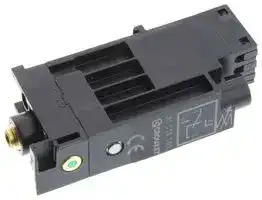
81513501
PRESSURE SW, SPDT, 0.3-1.2BAR, 5A/230V
⚠️ Reference pricing provided. In case of supply shortages, we will connect you with our trusted procurement partners to ensure your project's continuity.
- Manufacturer: CROUZET
- Product type: Pressure Switches
- Pressure Fitting Style:4mm Spout; Operating Pressure Min:0.3bar; Operating Pressure Max:1.2bar; Contact Configuration:SPDT; Sensor Mounting:DIN Rail; Electrical C
- SVHC: Lead
- Product Range: -
- Sensor Mounting: DIN Rail
- Contact Configuration: SPDT
- Electrical Connection: Screw
- Operating Pressure Max: 1.2bar
- Operating Pressure Min: 0.3bar
- Pressure Fitting Style: 4mm Spout
- Switching Current DC Resistive: 5A
- Switching Voltage DC Resistive: 230V
| Delivery and price | |
|---|---|
| Units per pack | 1 |
| Price | 73.02 € |
| Current stock | 10+ |
| Lead time | 22 days |
Datasheet

**|** WWW.CROUZET-CONTROL.COM

**| 35**

**|** PNEUMATICS PRODUCTS

## **PRESSURE SWITCHES VACUUM**

**|** WWW.CROUZET-CONTROL.COM

**| 36 |** PNEUMATICS PRODUCTS

**|** WWW.CROUZET-CONTROL.COM

**| 37**

**|** PNEUMATICS PRODUCTS

## **- Pressure switches vacuum (electrical output)**

**==> picture [494 x 566] intentionally omitted <==**

**----- Start of picture text -----**<br>
|||||||||||
|---|---|---|---|---|---|---|---|---|---|
|›|Conform to the Low Voltage Directive|
|›|Can be used without enclosure according to|
|IEC 664-1 pollution group III|
|Part numbers|
|Pressure and vacuum switches|81 513 552|81 513 502|81 513 501|81 513 522|
|Mounting|DIN rail|DIN rail|DIN rail|DIN rail|
|Actuators|Pressure|Pressure|Low pressure|Vacuum|
|Manual override|with|without|without|without|
|Symbol|
|Characteristics|
|Pneumatic|Push-in connection for semi-rigid mm|Ø 4 ext.|Ø 4 ext.|Ø 4 ext.|Ø 4 ext.|
|connection|tubing (NFE 49100)|
|-|-|-|-|
|Tapped BSP via connector|
|Protection|IEC 529|IP 20|IP 20|IP 20|IP 20|
|Permissible fluid: air, inert gases and liquids|●|●|●|●|
|Adjustment of switching pressure (* adjusted to 0.3)|bar|2 ➞ 8|2 ➞ 8|0.3 ➞ 1.2 *|-0.3 ➞ -0.8|
|Hysteresis|at 1 bar|bar|0.5|0.5|
|at 2 bars|bar|0.6|0.6|
|at 4 bars|bar|0.8|0.8|
|at 6 bars|bar|1|1|----|----|
|max. 200 mb|●|-|
|max. 250 mb|●|
|Pressure to break|---|---|--|-|
|Mechanical life (operations)|10|[6]|10|[6]|10|[6]|10|[6]|
|Contact rating (V resistive)|5A - 220-230 V|5A - 220-230 V|5A - 220-230 V|5A - 220-230 V|
|Wire cross-section|mm|[2]|0.75|0.75|0.75|0.75|
|Operating temperature|°C|-10 ➞|+70|-10 ➞|+70|-10 ➞|+70|-10 ➞|+70|
|Weight|g|48|46|46|46|
|Standard electrical contact|V4 83 170 4 I W2|V4 83 170 4 I W2|V4 83 170 4 I W2|V4 83 170 4 I W2|
|UL and cUL approval|MH15213 (R)|MH15213 (R)|MH15213 (R)|MH15213 (R)|
|Operation|Electrical life|
|Pressure operated|Vacuum operated|(Crouzet microswitch "V4" ref 83 170 4-1-W2)|
|Number of cycles|
|Electrical output-  common- normally closed contact|Inductive circuit Resistive circuit|{|Lc      Ra|[__]|cos q = 0.8 = 5 ms|
|- normally open cont|a|ct|Mechanical|
|life|
|Adjustment of switching pres-|
|sure 1 to 8 bars|
|ti|s|Pin|e|oe|
|Standard microswitch|
|5 A / 220 V|
|Manual override|
|Pneumatic indicator|
|L|F|=|1|=a|oN|
|Marking tag|Current|
|in Amps|
|Pneumatic signal|
|For continuous vacuum appli-|
|cations, please consult us.|

**----- End of picture text -----**<br>


**==> picture [510 x 483] intentionally omitted <==**

**----- Start of picture text -----**<br>
|||||||||||||||
|---|---|---|---|---|---|---|---|---|---|---|---|---|---|
|81 513 516|81 513 510|81 513 527|81 513 533|81 513 523|81 509 080|81 509 085|
|Base mounted|Base mounted|Base mounted|2 screws M4|2 screws M4|Base mounted|Base mounted|
|page 4/14|page 4/14|page 4/14|page 4/14|page 4/14|
|Pressure|Pressure|Vacuum|Pressure|Vacuum|Pressure|Pressure|
|without|with|without|without|without|without|with|
|Ø 4 ext.|Ø 4 ext.|Ø 4 ext.|-|--|-|-|
|-|-|-|1/8 BSP|1/8 BSP|Via sub-base|Via sub-base|
|IP 54|IP 54|IP 54|IP 54|IP 54|IP 54|IP 54|
|●|●|●|●|●|●|●|
|2 ➞ 8|2 ➞ 8|-0.3 ➞|-0.9|2 ➞ 8|-0.3 ➞|-0.8|1.4 ± 0.5|1.4 ± 0.5|
|0.5|0.5|0.5|
|0.6|0.6|0.6|
|0.8|0.8|0.8|
|1|1|----|1|----|
|-|-|-|-|
|●|●|------|------|
|--|--|-|---|-|0.6|[± 0.2]|0.6|[± 0.2]|
|10|[6]|10|[6]|10|[6]|10|[6]|10|[6]|10|[6]|10|[6]|
|5A - 220-230 V|5A - 220-230 V|5A - 220-230 V|5A - 220-230 V|5A - 220-230 V|5A - 220-230 V|5A - 220-230 V|
|0.75|0.75|0.75|0.75|0.75|1.5|1.5|
|-10 ➞|+70|-10 ➞|+70|-10 ➞|+70|-10 ➞|+70|-10 ➞ +70|-10 ➞|+70|-10 ➞ +70|
|56|58|56|65|65|80|80|
|V4 83 170 4 I W2|V4 83 170 4 I W2|V4 83 170 4 I W2|V4 83 170 4 I W2|V4 83 170 4 I W2|83 133 004|83 133 004|
|MH15213 (R)|MH15213 (R)|MH15213 (R)|MH15213 (R)|MH15213 (R)|
|Electrical connections|Dimensions|Pressure switch with connector|81 516 082|
|81 513 501 - 81 513 502|81 513 552 - 81 513 502|81 513 516 - 81 513 510|81 513 533|
|81 513 522 - 81 513 552|81 513 501 - 81 513 522|81 513 527|81 513 523|
|1 - Common|
|4 - NO contact|
|81 513 510|©|2 - NC contact|Hy|PAO)|=|
|81 513 516 - 81 513 527|
|For M4 screws|
|length 24 mm|
|81 513 533|
|81 513 523 - 81 513 533|Pilot|
|oe|iL ee|—|bath Ops|
|Pilot signal|signal|
|81 509 080 - 81 509 085|

**----- End of picture text -----**<br>


## **Other information**

On request :

- Microswitch V4 ref. 83 170 0 i W2 high current

- Microswitch V4 ref. 83 170 9 i W2 low current

**|** WWW.CROUZET-CONTROL.COM

**| 38 |** PNEUMATICS PRODUCTS

**|** WWW.CROUZET-CONTROL.COM

**| 39 |** PNEUMATICS PRODUCTS

## **Adjustable pressure switches (manostats) (pneumatic output)**

## **Adjustable vacuum switches (vacuostat)**

**==> picture [83 x 10] intentionally omitted <==**

**----- Start of picture text -----**<br>
› 100 % pneumatic<br>**----- End of picture text -----**<br>


**==> picture [83 x 9] intentionally omitted <==**

**----- Start of picture text -----**<br>
› 100 % pneumatic<br>**----- End of picture text -----**<br>


**==> picture [128 x 9] intentionally omitted <==**

**----- Start of picture text -----**<br>
› For vacuum  -0,1  ➞  -0,9 Bar<br>**----- End of picture text -----**<br>


Also available in **ATEX** version for use in potentially explosive atmospheres in accordance with 94/9/EC Directive

**Part numbers (and adjustment ranges)** Adjustment range 50 → 500 mb **81 505 140 81 502 140** 0.1 → 2.5 b **81 505 150 81 502 150** 2 → 8 b **81 505 160 81 502 160** Version Positive output Negative output Accuracy 50 → 500 mb 10 % 10 % 0.1 → 2.5 b 4 % 4 % 2 → 8 b 4 % 4 % **Symbol** ~~oe~~ ra 1 3 cp 2 2 **Characteristics** Orifice diameter mm 2.5 2.5 Flow at 4 bars Nl/min 170 170 Hysteresis 50 → 500 mb 60 mb 60 mb 0.1 → 2.5 b 100 mb 100 mb 2 → 8 b 320 mb 320 mb Connection - sub-base pages 54/55 ● ● ~~ee~~ Operating temperature Mechanical life °operationsC -3 x 10⁵ ➞ +50[6] -3 x 10⁵ ➞ +50[6] Weight g 160 160 ~~Oo~~ **Connections** Example of pressure threshold adjustment ~~@~~ (mini-regulator - manostat)

## **Part numbers**

|**81 505 110**|**81 502 110**|**81 508 110**|
|---|---|---|
|Positive output|Negative output|Electrical output|


|**Symbol**|||||||||
|---|---|---|---|---|---|---|---|---|
||||||||2)|[4|
||||2||2|2|oe|©)|
|Adjustment range<br>Flow at 6 bars<br>**Characteristics**|-0.1➞ -0.9<br>170<br>-0.1➞ -0.9<br>170<br>-0.1➞ -0.9<br>170<br>b<br>Nl/min<br>~~‘e~~<br>~~Oo~~<br>~~O~~<br>~~1~~<br>~~3~~<br>~~Ee~~||||||||
|Hysteresis||mb|80|80||80|||
|Connection-sub-base pages 54/55||||●||●|●||
|Operating temperature||°C|-5➞+50|-5|5➞+50|-5➞+50|||
|Mechanical life||operations|3 x 10⁶|3 x 10⁶||3 x 10⁶|||
|Weight||g|160|160||180|||
|**Connections**|||||||||
|Example of use:|||||||||
|Vacuum handling (vacuum generator,<br>vacuum pad, vacuostats).||:an|:<br>an|23<br>Te|||||


## **Principle of operation**

## **Principle of operation**

The manostats provide an on or off output signal when the input signal reaches a predetermined pressure threshold.

**==> picture [386 x 138] intentionally omitted <==**

**----- Start of picture text -----**<br>
Positive output Negative output<br>Output signal Pilot Output signal Pilot<br>" JE<br>Hysteresis cia | ' Hysteresis<br>Switching Switching<br>on 4 oka aes on eulr-<br>Switching off Switching off<br>ee CAE |<br>L = 1 $243<br>Dimensions<br>81 502 140 - 81 502 150 - 81 502 160<br>81 505 140 - 81 505 150 - 81 505 160<br>**----- End of picture text -----**<br>


**==> picture [451 x 166] intentionally omitted <==**

**----- Start of picture text -----**<br>
Vacuostats provide an on or off output signal when the input signal reaches a predetermined pressure threshold.<br>Positive output Negative output<br>Cc<br>Output signal i eS Output signal t<br>to ier a<br>0 Switching off = — = Switching off<br>Switching Switching<br>on on<br>_ if<br>Hysteresis Hysteresis<br>Vacuum Vacuum Vacuum<br>Vacuum<br>Dimensions<br>81 508 110<br>81 502 110 - 81 505 110<br>**----- End of picture text -----**<br>


**Other information** Pressure switches with electrical output on request.

**ATEX** version products are available in the following catologues: **Pneumatic products for explosive atmospheres** or on our website **www.crouzet.com**

**|** WWW.CROUZET-CONTROL.COM

**| 40**

**|** PNEUMATICS PRODUCTS

## **Vacuum handling components**

**› Sur le principe du Venturi › Facilement raccordable** Also available in **ATEX** version for use in poten© tially explosive atmospheres in accordance with 94/9/EC Directive

## **Part numbers**

**==> picture [445 x 261] intentionally omitted <==**

**----- Start of picture text -----**<br>
Vacuum generators 81 535 301 81 545 001 81 545 005<br>Sub-base mounting Plug-in Plug-in<br>+ 3<br>2 4/7 1y<br>LPS a<br>3<br>Characteristics<br>Push-in connectors for   Male/Female/Female (MFF) - Ø 4 mm -<br>semi-rigid tubing   Female/Female/ - - Ø 6 mm<br>(NFE 49100)  Female (FFF)<br>Operating pressure  bar 2 → 8 2 → 8 2 → 8<br>Vacuum pad material  - - -<br>Weight  g 80 13 25<br>Detection of the pressure decrease can be achieved by the<br>use of manostats (see pages 38/39)<br>Vacuum (mb) Vacuum (mb) Vacuum (mb)<br>Suction flow Suction flow Suction flow<br>700) £7            (mb)Vacuum 700) a,            (mb)  | Vacuum 800}700 Fp 7<br>400]neoe16}noffNoTT i Flow ey400]2,6nay| ae Flow 400]mole8)            (mb) H Vacuum<br>Flow<br>ao} HT sco}? | EEC goo} 7<br>200 SEH ‘co ELECT 200] €<br>oO COT.123456789 ie) 123456789CAP 160]° 5 120456789 ~<br>Supply pressure (bar) Supply pressure (bar) Supply pressure (bar)<br>**----- End of picture text -----**<br>


**==> picture [423 x 224] intentionally omitted <==**

**----- Start of picture text -----**<br>
Dimensions<br>81 535 301  81 545 001<br>Sub-base mounting 81 531… and 81 532…<br>2 push-in connectors<br>23 < 36 Ø 4 mm Plug-in ferrule for push-in connector<br>Ø 4 mm<br>ad = _<br>P j 12 0 C4, Bid<br>4, a _]<br>32| Soyar _ 29 I 11<br>40<br>:°$£——___———|<br>81 545 005<br>>_> 30,7<br>10,7 Ø 4,5 15,5<br>|__|<br>1ee© @1 |<br>== KY,<br>| i Sq<br>— 3 push-in connectors  ©)KZ<br>Ø 6 mm<br>40 14,5  [±0,1]<br>_ | |<br>24<br>11 ±0,1<br>29<br>**----- End of picture text -----**<br>


**ATEX** version products are available in the following catologues: **Pneumatic products for explosive atmospheres** or on our website **www.crouzet.com**
Updated at June 9, 2026
About Novapart
Novapart is a B2B electronic component broker specialising in stock shortages and cost reduction. We source hard-to-find parts and identify compliant alternatives across a catalogue of 410,000+ components from 500+ manufacturers.
Learn more →Stock Shortage Specialist
When a component is unavailable, discontinued or has an unacceptable lead time, we tap into our network of vetted European and Asian distributors to source what you need — without compromising on quality or traceability.
Request a quote →Compliant Alternatives
We identify pin-to-pin, electrically equivalent substitutes that meet the same certifications (RoHS, AEC-Q100, REACH) as your original specification — validated against datasheets, not just part numbers. Often at a lower cost.
BOM Analysis service →