
Image not available
Illustrative purposes only

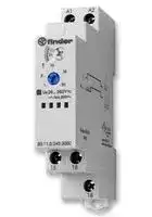
80.11.0.240.0000
Time Delay Relay, 100 ms, 24 h, 80 Series, SPDT, 16 A
⚠️ Reference pricing provided. In case of supply shortages, we will connect you with our trusted procurement partners to ensure your project's continuity.
- Manufacturer: FINDER
- Product type: Time Delay Relays - Electromechanical
- Product Range:80 Series; Timer Functions:On-Delay; Time Min:0.1s; Time Max:24h; No. of Timing Ranges:6Ranges; Timer Output:1 Changeover Relay; Supply Voltage Max:240V; Current Rat
- SVHC: No SVHC (04-Feb-2026)
- Time Max: 24h
- Time Min: 100ms
- Product Range: 80 Series
- Relay Mounting: DIN Rail
- Contact Current: 16A
- Relay Terminals: Screw
- Nom Input Voltage: 240VAC
- Timing Adjustment: Screwdriver Slot
- Contact Voltage VAC: 250V
- Contact Voltage VDC: -
- Contact Configuration: SPDT
| Delivery and price | |
|---|---|
| Units per pack | 10 |
| Price | 41.52 € |
| Current stock | 200+ |
| Lead time | 30 days |
Datasheet

**80 SERIES**

**Multi-function and mono-function timer range**

**==> picture [26 x 7] intentionally omitted <==**

**----- Start of picture text -----**<br>
80.01<br>**----- End of picture text -----**<br>


**==> picture [26 x 7] intentionally omitted <==**

**----- Start of picture text -----**<br>
80.11<br>**----- End of picture text -----**<br>


## **80.01 -  Multi-function & multi-voltage**

## **80.11 -  On-delay, multi-voltage**

- 17.5 mm wide

- Six time scales from 0.1 s to 24 h

- High input/output isolation

- 35 mm rail (EN 60715) mount

- “Blade + cross” - both flat blade and cross head screw drivers can be used to adjust the range and function selectors, the timing trimmer, and to disengage the rail mounting clip

- New multi-voltage versions with “PWM clever” technology

80.01 / 80.11

Screw terminal

- Multi-voltage

- Multi-function

**AI:** On-delay

**DI:** Interval

**SW:** Symmetrical flasher (starting pulse on)

- Multi-voltage

- Mono-function

**AI:** On-delay

**BE:** Off-delay with control signal

**CE:** On- and off-delay with control signal

**DE:** Interval with control signal on

## _For UL ratings see:_

## _“General technical information” page_ V

||||Wiring diagram<br>Wiring diagram|Wiring diagram<br>Wiring diagram|||Wiring diagram|
|---|---|---|---|---|---|---|---|
||For outline drawing see page 6||(without control signal)<br>(with control signal)|ntrol signal)|||(without~~c~~ontrol signal)|
||**Contact specification**<br>Contact configuration||1 CO (SPDT)||||1 CO (SPDT)|
||Rated current/Maximum peak current<br>A||16/30||||16/30|
||Rated voltage/<br>Maximum switchingvoltage|V AC|250/400||||250/400|
||Rated load AC1|VA|4000||||4000|
||Rated load AC15 (230 V AC)|VA|750||||750|
||Single phase motor rating (230 V AC)<br>kW||0.55||||~~0.~~55|
||Breaking capacity DC1: 30/110/220 V<br>A||16/0.3/0.12||||16/0.3/0.12|
||Minimum switching load|mW (V/mA)|500 (10/5)||||500 (10/5)|
||Standard contact material<br>**Supply specification**<br>Nominal voltage (UN)|V AC (50/60 Hz)|AgNi<br>12…240||||AgNi<br>24…240|
|||V DC|1~~2~~…240||||24…240|
||Rated power AC/DC|VA (50 Hz)/W|< 1.8/< 1||||< 1.8/< 1|
||Operating range|V AC|10.8…265||||16.8…265|
||**Technical data**|V DC|10.8…265||||16.8…265|
||Specified time range||(0.1…2)s, (1…20)s, (0.1…2)min, (1…20)min, (0.1…2)h, (1…24)h|||(0.1…2)s, (1…20)s, (0.1…2)min, (1…20)min, (0.1…2)h, (1…24)h||
||Repeatability|%|± 1||||± 1|
||Recovery time|ms|100||||100|
||Minimum control impulse|ms|50||||—|
|XI-2016, www.findernet.com|Setting accuracy-full range<br>Electrical life at rated load in AC1<br>Ambient temperature range<br>Protection category<br>**Approvals**(according to type)|%<br>cycles<br>°C|± 5<br>50 · 103<br>–10…+50<br>IP 20<br>~~Cé€ FAL~~|~~@ ~~|~~B ~~||± 5<br>50 · 103<br>–10…+50<br>IP 20<br> ~~RINA @«~~|


**H**

**1**

**80 SERIES**

## **Mono-function timer range**

## **80.21**

**==> picture [25 x 7] intentionally omitted <==**

**----- Start of picture text -----**<br>
80.41<br>**----- End of picture text -----**<br>


**==> picture [26 x 7] intentionally omitted <==**

**----- Start of picture text -----**<br>
80.91<br>**----- End of picture text -----**<br>


## **80.21 - Interval, multi-voltage**

## **80.41 - Off-delay with control signal, multi-voltage 80.91 - Asymmetrical flasher, multi-voltage**

- 17.5 mm wide

- Six time scales from 0.1 s to 24 h

- High input/output isolation

- 35 mm rail (EN 60715) mount

- “Blade + cross” - both flat blade and cross head screw drivers can be used to adjust the range and function selectors, the timing trimmer, and to disengage the rail mounting clip

- New multi-voltage versions with “PWM clever” technology

- Multi-volta ~~ge~~

- Mono-function

**DI:** Interval

- Multi-volta ~~ge~~

- Mono-function

**BE:** Off-delay with control signal

- Multi-voltage

- Mono-function

**LI:** Asymmetrical flasher

(starting pulse on)

80.21 / 80.41 / 80.91

Screw terminal

**LE:** Asy ~~m~~ metrical flasher (starting pulse on) with control signal

## _For UL ratings see:_

_“General technical information” page_ V

||_“General technical information” pageGeneral technical information” page” pagepage_|_“General technical information” pageGeneral technical information” page” pagepage_V||||||~~Wir~~ing diagram<br>~~Wir~~ing diagram||
|---|---|---|---|---|---|---|---|---|---|
||||Wiring diagram|Wiring diagram||||(without control<br>(with control||
||For outline drawing see page 6||(without control signal)|(with control signal)||||signal)<br>signal)||
||**Contact specification**<br>Contact configuration||1 CO (SPDT)|1 CO (SPDT)|1 CO (SPDT)|||1 CO (SPDT)||
|**H**|Rated current/Maximum peak current<br>A<br>Rated voltage/<br>Maximum switchingvoltage<br>V AC||16/30<br>250/400|16/30<br>250/~~4~~00||||16/30<br>250/400||
||Rated load AC1|VA|4000|4000||||4000||
||Rated load AC15 (230 V AC)|VA|750|750||||750||
||Single phase motor rating (230 V AC)<br>kW||0.55|0.55||||0.55||
||Breaking capacity DC1: 30/110/220 V<br>A||16/0.3/0.12|16/0.3/0.12||||16/0.3/0.12||
||Minimum switching load|mW (V/mA)|500 (10/5)|500 (10/5)|500 (10/5)|||500 (10/5)||
||Standard contact material<br>**Supply specification**<br>Nominal voltage (UN)|V AC (50/60 Hz)|AgNi<br>24…240|AgNi<br>24…240||||AgNi<br>12…240||
|||V DC|24…240|24…240||||12…240||
||Rated power AC/DC|VA (50 Hz)/W|< 1.8/< 1|< 1.8/< 1||||< 1.8/< 1||
||Operating range|V AC|16.8…265|16.8…265||||10.8…265||
||**Technical data**|V DC|16.8…265|16.8…265||||10.8…265||
||Specified time range||(0.1…2)s, (1…20)s, (0.1…2)min, (1…20)min, (0.1…2)h, (1…24)h|||||||
||Repeatability|%|± 1|± 1||||± 1||
||Recovery time|ms|100|100||||100||
||Minimum control impulse|ms|—|50||||50||
||Setting accuracy-full range<br>Electrical life at rated load in AC1<br>Ambient temperature range<br>Protection category<br>**Approvals**(according to type)|%<br>cycles<br>°C|± 5<br>50 · 103<br>–10…+50<br>IP 20<br>~~C€~~|± 5<br>50 · 103<br>–10…+50<br>IP 20<br>~~Fl&@BRINA@s«~~||||± 5<br>50 · 103<br>–10…+50<br>IP 20<br>~~@s«~~|XI-2016, www.findernet.com|


**2**

**80 SERIES**

**H**

## **Multi-function and multi-voltage solid-state output timer**

**==> picture [26 x 7] intentionally omitted <==**

**----- Start of picture text -----**<br>
80.71<br>**----- End of picture text -----**<br>


- 17.5 mm wide

- Six time scales from 0.1 s to 24 h

- High input/output isola ~~t~~ ion

- 35 mm rail (EN 60715) mount

- Multi-voltage output (24…240 V AC/DC), independent from the input voltage

- “Blade + cross” - both flat blade and cross head screw drivers can be used to adjust the range and function selectors, the timing trimmer, and to disengage the rail mounting clip

- Multi-voltage input with “PWM clever” technology

- Multi-voltage

- Multi-function

**AI:** On-delay

**DI:** Interval

80.71

Screw terminal

**SW:** Symmetrical flasher (starting pulse on)

**BE:** Off-delay with control signal

**CE:** On- and off-delay with control signal

**DE:** Interval with control signal on

||||Wiring diagram<br>Wiring diagram|
|---|---|---|---|
||For outline drawing see page 6||(without control signal)<br>(with control signal)|
||**Output circuit**<br>Contact configuration||1 NO (SPST-NO)|
||Rated current|A|1<br>~~|~~|
||Rated voltage|V AC/DC|24…240<br>~~a~~|
||Switching voltage range|V AC/DC|19…265<br>~~a~~|
||Rated load AC15<br>Rated load DC1<br>Minimum switching current<br>Max. “OFF-state” leakage current<br>Max. “ON-state” voltage drop<br>**Input circuit**<br>Nominal voltage (UN)|A<br>A<br>mA<br>mA<br>V<br>V AC (50/60 Hz)|1<br>1<br>0.5<br>0.05<br>2.8<br>24…240<br>~~a~~<br>~~CeCn~~<br>~~Ce~~|
|||V DC|24…240|
||Rated power<br>Operating range<br>**Technical data**|VA (50 Hz)/W<br>V AC<br>V DC|1.3/1.3<br>19…265<br>19…265<br>~~ee~~<br>~~ee~~|
||Specified time range||(0.1…2)s, (1…20)s, (0.1…2)min, (1…20)min, (0.1…2)h, (1…24)h|
||Repeatability<br>Recovery time|%<br>ms|± 1<br>100<br>~~Cone~~|
||Minimum control impulse|ms|50|
|XI-2016, www.findernet.com|Setting accuracy-full range<br>Electrical life<br>Ambient temperature range<br>Protection category<br>**Approvals**(according to type)|%<br>cycles<br>°C|± 5<br>100 · 106<br>–20…+50<br>IP 20<br>~~a~~<br>~~a~~<br>~~a~~<br>Cé€<br>HAL &<br>RINA|


**3**

**80 SERIES**

## **Mono-function timer range**

**==> picture [25 x 7] intentionally omitted <==**

**----- Start of picture text -----**<br>
80.61<br>**----- End of picture text -----**<br>


**==> picture [25 x 7] intentionally omitted <==**

**----- Start of picture text -----**<br>
80.82<br>**----- End of picture text -----**<br>


## **80.61 -  Power off-delay (True off-delay), multi-voltage**

## **80.82 - Star-delta, multi-voltage**

- 17.5 mm wide

- Rotary range selector, and timing trimmer

- Four time scales from 0.05s to 3 min (type 80.61)

- Six time scales from 0.1 s to 20min (type 80.82)

- High input/output isolation

- 35 mm rail (EN 60715) mount

80.61 / 80.82 Screw terminal

- Multi-voltage

- Mono-function

- M ~~u~~ lti-voltage

- Mono-function

- Transfer time can be regulated (0.05…1)s

**BI:** Power off-delay (True off-delay)

**SD:** Star-delta

## _For UL ratings see:_

_“General technical information” page_ V

Wiring diagram Wiring diagram For outline drawing see page 6 (without control signal) ( ~~wi~~ thout control signal) **Contact specification**

||**Contact specification**|**Contact specification**||
|---|---|---|---|
|**H**|Contact configuration<br>1 CO (SPDT)<br>2 NO (DPST-NO)<br>Rated current/Maximum peak current<br>A<br>8/15<br>6/10<br>Rated voltage/<br>Maximum switchingvoltage<br>V AC<br>2~~5~~0/400<br>250/400<br>~~rs~~<br>~~QR~~|||
||Rated load AC1|VA<br>2000<br>1500<br>~~a~~||
||Rated load AC15 (230 V AC)|VA<br>400<br>300<br>~~a~~||
||Single phase motor rating (230 V AC)<br>kW<br>0.3<br>—<br>~~a~~|||
||Breaking capacity DC1: 30/110/220 V<br>A<br>8/0.3/0.12<br>6/0.2/0.12<br>~~a~~|||
||Minimum switching load|mW (V/mA)<br>300 (5/5)<br>500 (12/10)<br>~~a~~||
||Standard contact material<br>**Supply specification**<br>Nominal voltage (UN)<br>Rated power AC/DC<br>Operating range<br>**Technical data**|AgNi<br>AgNi<br>V AC (50/60 Hz)<br>24…240<br>24…240<br>V DC<br>24…220<br>24…240<br>VA (50 Hz)/W<br>< 0.6/< 0.6<br>< 1.3/< 0.8<br>V AC<br>16.8…265<br>16.8…265<br>V DC<br>16.8…242<br>16.8…265<br>~~RRa~~<br>~~a~~||
||Specified time range|(0.05…2)s, (1…16)s, (8…70)s, (50…180)s<br>(0.1…2)s, (1…20)s, (0.1…2)min, (1…20)min||
||Repeatability|%<br>± 1<br>± 1<br>~~a~~||
||Recovery time|ms<br>—<br>100<br>~~a~~||
||Minimum control impulse|ms<br>500 (A1-A2)<br>—<br>~~eG~~||
||Setting accuracy-full range<br>Electrical life at rated load in AC1<br>Ambient temperature range<br>Protection category<br>**Approvals**(according to type)|%<br>± 5<br>± 5<br>cycles<br>100 · 103<br>60 · 103<br>°C<br>–10…+50<br>–10…+50<br>IP 20<br>IP 20<br>~~a~~<br>~~a~~<br>~~a~~<br>~~es~~<br>~~C€FAL~~<br>~~&GRINAOs~~|XI-2016, www.findernet.com|


**4**

**80 SERIES**

## **Ordering information**

Example:  80 series, modular timers, 1 CO (SPDT) - 16 A, supply rated at (12…240)V AC/DC.

||**8**<br>**0 **<br>**Series**<br>**Type**<br>0 =  Multi-function (AI, DI, SW, BE, CE, DE)<br>1 =  On-delay (AI)<br>2 =  Interval (DI)<br>4 =  Off-delay with control signal (BE)<br>6 =  Power off-delay (True off-delay) (BI)|**. **|**0**<br>**1 . 0 . 2**<br>**4**<br>**0 . 0**<br>**0**<br>**0**<br>**0**<br>**Versions**<br>0 =  Standard<br>**Supply voltage**<br>240 =  (12…240)V AC/DC (80.01, 80.91)<br>240 =  (24…240)V AC/DC (80.11, 80.21, 80.41, 80.71, 80.82)<br>240 =  (24…240)V AC, (24…220)V DC (80.61)<br>**Supply version**<br>[|pt Wooo|**0**<br>**1 . 0 . 2**<br>**4**<br>**0 . 0**<br>**0**<br>**0**<br>**0**<br>**Versions**<br>0 =  Standard<br>**Supply voltage**<br>240 =  (12…240)V AC/DC (80.01, 80.91)<br>240 =  (24…240)V AC/DC (80.11, 80.21, 80.41, 80.71, 80.82)<br>240 =  (24…240)V AC, (24…220)V DC (80.61)<br>**Supply version**<br>[|pt Wooo|**0**<br>**1 . 0 . 2**<br>**4**<br>**0 . 0**<br>**0**<br>**0**<br>**0**<br>**Versions**<br>0 =  Standard<br>**Supply voltage**<br>240 =  (12…240)V AC/DC (80.01, 80.91)<br>240 =  (24…240)V AC/DC (80.11, 80.21, 80.41, 80.71, 80.82)<br>240 =  (24…240)V AC, (24…220)V DC (80.61)<br>**Supply version**<br>[|pt Wooo|**0**<br>**1 . 0 . 2**<br>**4**<br>**0 . 0**<br>**0**<br>**0**<br>**0**<br>**Versions**<br>0 =  Standard<br>**Supply voltage**<br>240 =  (12…240)V AC/DC (80.01, 80.91)<br>240 =  (24…240)V AC/DC (80.11, 80.21, 80.41, 80.71, 80.82)<br>240 =  (24…240)V AC, (24…220)V DC (80.61)<br>**Supply version**<br>[|pt Wooo|**0**<br>**1 . 0 . 2**<br>**4**<br>**0 . 0**<br>**0**<br>**0**<br>**0**<br>**Versions**<br>0 =  Standard<br>**Supply voltage**<br>240 =  (12…240)V AC/DC (80.01, 80.91)<br>240 =  (24…240)V AC/DC (80.11, 80.21, 80.41, 80.71, 80.82)<br>240 =  (24…240)V AC, (24…220)V DC (80.61)<br>**Supply version**<br>[|pt Wooo|**0**<br>**1 . 0 . 2**<br>**4**<br>**0 . 0**<br>**0**<br>**0**<br>**0**<br>**Versions**<br>0 =  Standard<br>**Supply voltage**<br>240 =  (12…240)V AC/DC (80.01, 80.91)<br>240 =  (24…240)V AC/DC (80.11, 80.21, 80.41, 80.71, 80.82)<br>240 =  (24…240)V AC, (24…220)V DC (80.61)<br>**Supply version**<br>[|pt Wooo|**0**<br>**1 . 0 . 2**<br>**4**<br>**0 . 0**<br>**0**<br>**0**<br>**0**<br>**Versions**<br>0 =  Standard<br>**Supply voltage**<br>240 =  (12…240)V AC/DC (80.01, 80.91)<br>240 =  (24…240)V AC/DC (80.11, 80.21, 80.41, 80.71, 80.82)<br>240 =  (24…240)V AC, (24…220)V DC (80.61)<br>**Supply version**<br>[|pt Wooo|**0**<br>**1 . 0 . 2**<br>**4**<br>**0 . 0**<br>**0**<br>**0**<br>**0**<br>**Versions**<br>0 =  Standard<br>**Supply voltage**<br>240 =  (12…240)V AC/DC (80.01, 80.91)<br>240 =  (24…240)V AC/DC (80.11, 80.21, 80.41, 80.71, 80.82)<br>240 =  (24…240)V AC, (24…220)V DC (80.61)<br>**Supply version**<br>[|pt Wooo||
|---|---|---|---|---|---|---|---|---|---|---|---|
||7 =  Multi-function with solid state output|7 =  Multi-function with solid state output||||||0 =  AC (50/60 Hz)/DC||||
||(AI, DI, SW, BE, CE, DE)<br>8 =  Star-delta (SD)<br>9 =  Asymmetrical flasher (LI, LE)|||||||**No. of poles**<br>1 =  1 CO (SPDT)<br>1 =  1 NO (SPST-NO), type 80.71 only||||
|||||||||2 =  2 NO (DPST-NO), type 80.82 only||||
||**Technical data**|||||||||||
|**Insulation**||||||||||||
|Dielectric strength||||||||**80.01/11/21/41/82/91**<br>**80.61**||**80.71**||
||between input and output circuit<br>between open contacts||||||V AC 4000<br>2500<br>V AC 1000<br>1000<br>~~ee~~<br>~~po~~|||2500<br>—||
|Insulation (1.2/50 µs) between input and output||||||||kV 6<br>4||4||
|**EMC specifications**||||||||||||
|**Type of test**||||||||**Reference standard**<br>**80.01/11/21/41/61/71/91**||**80.82**||
|Electrostatic discharge|||contact discharge|||||EN 61000-4-2<br>4 kV<br>~~ee~~||4 kV||
|Radio-frequencyelectromagnetic field(80 ÷ 1000 MHz|||air discharge<br>80 ÷ 1000 MHz)|||||EN 61000-4-2<br>8 kV<br>EN 61000-4-3<br>10 V/m<br>~~ee~~<br>~~ee~~||8 kV<br>10 V/m||
|Fast transients(burst) (5-50 ns,5 kHz)on Supplyterminals<br>Surges (1.2/50 µs) on Supply terminals<br>common mode||||||||EN 61000-4-4<br>4 kV<br>EN 61000-4-5<br>4 kV<br>~~ee~~<br>~~ee~~||4 kV<br>4 kV||
||||differential mode|||||EN 61000-4-5<br>4 kV<br>~~ee~~||4 kV||
|on start terminal (B1)<br>common mode<br>differential mode<br>Radio-frequencycommon mode(0.15 ÷ 80 MHz)on Supplyterminals<br>Radiated and conducted emission||||||||EN 61000-4-5<br>4 kV<br>4 kV<br>EN 61000-4-5<br>4 kV<br>4 kV<br>EN 61000-4-6<br>10 V<br>10 V<br>EN 55022<br>class B<br>class A<br>~~ee~~<br>~~po~~<br>~~pO~~|||**H**|
|**Other data**||||||||||||
|Current absorption on signal control(B1)||||||||< 1 mA||||
|Power lost to the environment|||without contact current W|||||without contact current W 1.4||||
||||with rated current|||with rated current||W 3.2||||
|Screw torque<br>©|||||||Nm 0.8|||||
|Max. wire size||||||||solid cable<br>stranded cable<br>~~po~~||||
||||||||mm2 1 x 6 / 2 x 4<br>1 x 4 / 2 x 2.5<br>~~po~~|||||
||||||||AWG 1 x 10 / 2 x 12<br>1 x 12 / 2 x 14<br>~~po~~|||||


**Accessories**

**020.24**

|**Sheet of marker tags**, for types 80.82, plastic, 24 tags, 9 x 17 mm|020.24|
|---|---|
|||
|**Sheet of marker tags (CEMBRE'S Thermal transfer printers)**for relays types<br>80.01/11/21/41/61/71 (48 tags), 6 x 12 mm|060.48|


**060.48**

**5**

**80 SERIES**

## **Outline drawings**

**==> picture [29 x 53] intentionally omitted <==**

**----- Start of picture text -----**<br>
H<br>**----- End of picture text -----**<br>


80.01 Screw terminal

**==> picture [130 x 151] intentionally omitted <==**

**==> picture [44 x 16] intentionally omitted <==**

**----- Start of picture text -----**<br>
80.21<br>Screw terminal<br>**----- End of picture text -----**<br>


**==> picture [131 x 151] intentionally omitted <==**

**==> picture [44 x 15] intentionally omitted <==**

**----- Start of picture text -----**<br>
80.91<br>Screw terminal<br>**----- End of picture text -----**<br>


**==> picture [120 x 151] intentionally omitted <==**

**==> picture [44 x 15] intentionally omitted <==**

**----- Start of picture text -----**<br>
80.61<br>Screw terminal<br>**----- End of picture text -----**<br>


**==> picture [130 x 151] intentionally omitted <==**

**==> picture [45 x 16] intentionally omitted <==**

**----- Start of picture text -----**<br>
80.11<br>Screw terminal<br>**----- End of picture text -----**<br>


**==> picture [131 x 151] intentionally omitted <==**

**==> picture [45 x 16] intentionally omitted <==**

**----- Start of picture text -----**<br>
80.41<br>Screw terminal<br>**----- End of picture text -----**<br>


**==> picture [131 x 151] intentionally omitted <==**

**==> picture [45 x 15] intentionally omitted <==**

**----- Start of picture text -----**<br>
80.71<br>Screw terminal<br>**----- End of picture text -----**<br>


**==> picture [130 x 151] intentionally omitted <==**

**==> picture [45 x 15] intentionally omitted <==**

**----- Start of picture text -----**<br>
80.82<br>Screw terminal<br>**----- End of picture text -----**<br>


**==> picture [52 x 141] intentionally omitted <==**

**==> picture [42 x 93] intentionally omitted <==**

**6**

**80 SERIES**

## **Functions**

||LED*|Supply voltage|NO output<br>contact|Contacts|Contacts|
|---|---|---|---|---|---|
|||||Open|Closed|
|||OFF|Open|15 - 18|15 - 16|
|||||||
|||ON|Open|15 - 18|15 - 16|
|||||||
|||ON|Open<br>(Timingin Progress)|15 - 18|15 - 16|
|||||||
|||ON|Closed|15 - 16|15 - 18|


- The LED on type 80.61 is illuminated only when the supply voltage is applied to the timer; during the timing period the LED is not illuminated.

Without control signal = Start via contact in supply line (A1).

## **Wiring diagram**

With control signal = Start via contact into control terminal (B1).

**==> picture [512 x 360] intentionally omitted <==**

**----- Start of picture text -----**<br>
Without control signal Type (AI) On-delay.<br>80.01 Apply power to timer. Output contacts transfer after preset<br>80.71 time has elapsed. Reset occurs when power is removed.<br>(DI) Interval.<br>Apply power to timer. Output contacts transfer immediately.<br>80.01 After the preset time has elapsed, contacts reset.<br>(SW) Symmetrical flasher (starting pulse on).<br>Apply power to timer. Output contacts transfer immediately<br>and cycle between ON and OFF for as long as power is applied.<br>The ratio is 1:1 (time on = time off).<br>80.71<br>With control signal 80.01 (BE) Off-delay with control signal.<br>80.71 Power is permenently applied to the timer. The output<br>contacts transfer immediately on closure of the Signal Switch<br>(S). Opening the Signal Switch initiates the preset delay, after<br>which time the output contacts reset.<br>(CE) On- and off-delay with control signal.<br>80.01 Power is permenently applied to the timer. Closing the Signal<br>Switch (S) initiates the preset delay, after which time the output<br>contacts transfer. Opening the Signal switch initiates the same<br>preset delay, after which time the output contacts reset.<br>(DE) Interval with control signal on.<br>Power is permenently applied to the timer.<br>On momentary or maintained closure of Signal Switch (S), the<br>80.71<br>output contacts transfer, and remain so for the duration of the<br>preset delay, after which they reset.<br>**----- End of picture text -----**<br>


**H**

NOTE: The function must be set before energising the timer.

**==> picture [66 x 66] intentionally omitted <==**

- Possible to control an external load, such as another relay coil or timer, connected to the control signal terminal B1.

- With DC supply, positive polarity has to be connected to B1 terminal (according to EN 60204-1).

- **  A voltage other than the supply voltage can be applied to the command Start (B1), example: A1 - A2 = 230 V AC

B1 - A2 = 12 V DC

**7**

**80 SERIES**

**H**

## **Functions**

## **Wiring diagram**

|Without control<br> 80.11/21/61<br>8~~0~~.82|signal<br>**Type**<br>**80.11**<br>**80.21**<br>**80.61**<br>**80.82**|**(AI) On-delay.**<br>Apply power to timer. Output contacts transfer after preset<br>time has elapsed. Reset occurs when power is removed.<br>**(DI) Interval.**<br>Apply power to timer. Output contacts transfer immediately.<br>After the preset time has elapsed, contacts reset.<br>**(BI) Power off-delay (True off-delay).**<br>Apply power to timer (minimum 500 ms). Output contacts<br>transfer immediately. Removal of power initiates the preset<br>delay, after which time the output contacts reset.<br>**(SD)Star-delta.**<br>Apply power to timer. The star contact (<br> ) closes immediately.<br>After preset delay has elapsed the star contact (<br> ) resets.<br>After a further transfer time variable from (0.05…1)s the delta<br>contact (∆) closes and remains in that position, until reset on<br>power off.|
|---|---|---|
|Withcontrol sign<br>80.41|al<br>**80.41**|**(BE) Off-delay with control signal.**<br>Power is permenently applied to the timer.<br>The output contacts transfer immediately on closure of the<br>Signal Switch (S). Opening the Signal Switch initiates the preset<br>delay, after which time the output contacts reset.|
|Without control<br>80.91<br>With co~~nt~~rol sign<br>80.91|signal<br>al<br>**80.91**|**(LI)Asymmetrical flasher (starting pulse on).**<br>Apply power to timer. Output contacts transfer immediately<br>and cycle between ON and OFF for as long as power is applied.<br>The ON (T1) and OFF (T2) times are independently adjustable.<br>**(LE)Asymmetrical flasher (starting pulse on) with control**<br>**signal**<br>Power is permenently applied to the timer.<br>Closing Signal Switch (S) causes the output contacts to transfer<br>immediately and cycle between ON (T1) and OFF (T2), until<br>opened.|


**==> picture [66 x 66] intentionally omitted <==**

- Possible to control an external load, such as another relay coil or timer, connected to the control signal terminal B1.

- With DC supply, positive polarity has to be connected to B1 terminal (according to EN 60204-1).

- **  A voltage other than the supply voltage can be applied to the command Start (B1), example: A1 - A2 = 230 V AC

B1 - A2 = 12 V DC

**8**
Updated at June 7, 2026
About Novapart
Novapart is a B2B electronic component broker specialising in stock shortages and cost reduction. We source hard-to-find parts and identify compliant alternatives across a catalogue of 410,000+ components from 500+ manufacturers.
Learn more →Stock Shortage Specialist
When a component is unavailable, discontinued or has an unacceptable lead time, we tap into our network of vetted European and Asian distributors to source what you need — without compromising on quality or traceability.
Request a quote →Compliant Alternatives
We identify pin-to-pin, electrically equivalent substitutes that meet the same certifications (RoHS, AEC-Q100, REACH) as your original specification — validated against datasheets, not just part numbers. Often at a lower cost.
BOM Analysis service →