
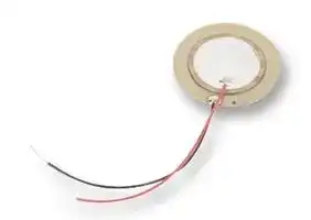


7BB-35-3L0
Transducer, Piezo, Sounder, Diaphragm
- Manufacturer: MURATA
- Product type: Piezo Transducers
- Resonant Frequency: 2.8kHz
- Transducer Function: Diaphragm
| Delivery and price | |
|---|---|
| Units per pack | 400 |
| Price | 0.574 € |
| Current stock | 10+ |
| Lead time | 30 days |
## Piezoelectric Sound Components

!Note[• Please read rating and ][!][CAUTION (for storage, operating, rating, soldering, mounting and handling) in this catalog to prevent smoking and/or burning, etc.] • This catalog has only typical specifi cations. Therefore, please approve our product specifi cations or transact the approval sheet for product specifi cations before ordering.

## **EU RoHS Compliant**

!Note[• Please read rating and ][!][CAUTION (for storage, operating, rating, soldering, mounting and handling) in this catalog to prevent smoking and/or burning, etc.] • This catalog has only typical specifi cations. Therefore, please approve our product specifi cations or transact the approval sheet for product specifi cations before ordering.

1

2

3

4

5

6

## Contents

Product specifications are as of May 2014. PIEZORINGERr and "PIEZORINGER" in this catalog are the trademarks of Murata Manufacturing Co., Ltd.

|Part Numbering<br>p2<br>Application Matrix<br>p4|Part Numbering<br>p2<br>Application Matrix<br>p4|Part Numbering<br>p2<br>Application Matrix<br>p4|
|---|---|---|
||erng<br>on Matrix||
|Piezoele<br>External<br>Self Driv<br>Piezo<br>1|ctric Diaphragms<br>Drive Type<br>e Type<br>electric Diaphragms Notice|p5<br>p5<br>p6<br>p7|
|Piezoele<br>Piezo<br>(Exter<br>2|ctric Sounders External Drive Pin Type<br>electric Sounders<br>nal Drive Pin Type) Circuit/Notice|p8<br>p12|
|Piezoele<br>Taping<br>Piezo<br>(Exter<br>3|ctric Sounders External Drive Pin Type|p13<br>p15|
||electric Sounders<br>nal Drive Pin Type Taping) Circuit/Notice||
|Piezoele<br>Piezo<br>(Exter<br>4|ctric Sounders External Drive SMD Type<br>electric Sounders<br>nal Drive SMD Type) Circuit/Notice|p16<br>p19|
|Piezoele<br>Piezo<br>5|ctric Sounders Self Drive Pin Type<br>electric Sounders (Self Drive) Notice|p20<br>p21|
|Piezoele<br>Piezo<br>6|ctric Buzzers Pin Type<br>electric Buzzers Notice|p22<br>p23|
|Piezoelectric Sound Components Notice<br>p24<br>Package<br>p25|ctric Sound Components Notice<br>||


Please check the MURATA home page (http://www.murata.com/) if you cannot find the part number in the catalog.

!Note[• Please read rating and ][!][CAUTION (for storage, operating, rating, soldering, mounting and handling) in this catalog to prevent smoking and/or burning, etc.]

• This catalog has only typical specifi cations. Therefore, please approve our product specifi cations or transact the approval sheet for product specifi cations before ordering.

## o Part Numbering

Piezoelectric Diaphragms

|y<br>**-1R5**<br>e<br>**B**<br>w<br>**N**<br>r<br>**-31R2**<br>t<br>**DM**<br>u<br>i<br>**L**<br>o<br>**10**<br>q<br>**7**<br>qProduct ID<br>wMaterial<br>eProduct<br>**7**<br>Ceramic Material<br>**B**<br>**N**<br>**S**<br>Brass<br>Nickel Alloy<br>SUS<br>**B**<br>Piezoelectric Diaphragms<br>Product<br>Product ID<br>Code<br>Metal Plate Material<br>Code<br>(Part Number)<br>rMetal Plate Diameter<br>**-31R2**<br>Metal Plate Diameter<br>Code<br>A hyphen (-) plus four-digit alphanumerics<br>express metal plate outer dimensions. A<br>decimal point is expressed by the capital letter<br>"**R**."|**7**|**N**|**B**|**-31R2**|**DM**|**-1R5**||**L**|**10**|
|---|---|---|---|---|---|---|---|---|---|
|Code||||||||||
|**-31R2**||||||||||


If there is no decimal point, the decimal point code is omitted.

## tForm of Piezoelectric Style

Code Form of Piezoelectric Style **DM** Two digits express the shape of ceramics. For an Ag electrode, this digit remains blank; the corresponding code is omitted.

## yResonant Frequency Type

Code Resonant Frequency (kHz) A hyphen (-) and three-digit alphanumerics **-1R5** express resonant frequency. A decimal point is expressed by the capital letter " **R** ."

If there is no decimal point, the decimal point code is omitted.

## uWith Feedback Electrode

|Code|With Feedback Electrode|
|---|---|
|**C**|With Feedback Electrode|
|e|Without Feedback Electrode|
|iProduct Specification||
|Code|Product Specification|
|**L**|With lead (available for RoHS)|
|e|No lead (omitted)|


## oIndividual Specification Code

|Code|Individual Specification Code|
|---|---|
|**10**|These digits express a lead length, lead<br>number, and the presence/absence of a<br>connector.|


If the product has no individual specification, the corresponding code is omitted.

2

!Note[• Please read rating and ][!][CAUTION (for storage, operating, rating, soldering, mounting and handling) in this catalog to prevent smoking and/or burning, etc.]

• This catalog has only typical specifi cations. Therefore, please approve our product specifi cations or transact the approval sheet for product specifi cations before ordering.

## Piezoelectric Sounders/Piezoelectric Buzzers/Piezoelectric Ringers (PIEZORINGERr)

|y<br>**YH**<br>e<br>**13**<br>w<br>**M**<br>r<br>**E**<br>t<br>**P**<br>u<br>**40**<br>i<br>**00**<br>o<br>**P**<br>!<br>**-A0**<br>q<br>**PK**<br>qProduct ID<br>wProduct<br>yStructure<br>**PK**<br>Piezoelectric Sound Components<br>**T**p<br>**P**p<br>**Y**p<br>**C**p<br>p<br>**M**<br>**B**<br>Sounder, Ringer<br>Buzzer<br>Standing Type<br>Flat Type Auto-assemble<br>Flat Type/Available for Taping<br>Flat Type/Semi-auto-assemble<br>Exclude above mentioned<br>Product<br>Product ID<br>Code<br>Code<br>Structure<br>(Part Number)<br>Pin Type<br>Lead Wire Type<br>eOuter Dimensions<br>rDrive<br>**E**<br>**S**<br>Drive<br>Code<br>tOuter Electrode Style<br>**P**<br>**W**<br>Outer Electrode Style<br>Code<br>Expressed by two figures in mm.<br>**13**<br>Ex.)<br>ø12.6mm<br>External-Drive<br>Self-Drive<br>Code<br>Outer Dimensions|**PK**|**M**|**13**|**E**|**P**|**YH**|**40**|**00**|**P**|**-A0**|
|---|---|---|---|---|---|---|---|---|---|---|
|Code|||||||||||
|**T**p|||||||||||
|**P**p|||||||||||
|**Y**p|||||||||||
|**C**p|||||||||||
|p|||||||||||


## uOscillating Frequency Type

Code Oscillating Frequency Type Expressed resonant frequency by two-digit **40** alphanumerics.  The unit is in 100 hertz (Hz). In case of 4kHz (4000Hz), expressed as "40."

## iIndividual Specification Code

|Code|Individual Specification Code|
|---|---|
|**00**|Two digits express custom specification in<br>characteristics.|


## oSpecial Quality Guarantee

|Code|Special Quality Guarantee|
|---|---|
|**P**|Post Plated Terminal|
|Y|Blank|
|!Packaging||
|Code|Packaging|
|**-B0**|Bulk|
|**-A0**|Radial Taping|


Radial taping is not available for all types. Please contact us.

p signifies specification of the outer electrode.

## SMD Piezoelectric Sounder

|SMD Piezoelectric Sounder|SMD Piezoelectric Sounder|
|---|---|
|qProduct ID<br>(Part Number)<br>y<br>**01**<br>e<br>**1212**<br>w<br>**LCS**<br>r<br>**E**<br>t<br>**40**<br>u<br>**-R1**<br>q<br>**PK**||
|Product ID||
|**PK**|Piezoelectric Sound Components|
|wProduct||
|Code|Product|
|**LCS/MCS**|SMD Sounder|
|eDimensions||
|Code|Outer Dimensions|
|**1212**|p12mm|
|**0909**|p9mm|
|rDrive||
|Code|Drive|
|**E**|External Drive|


## tOscillating Frequency Type

|Code|Oscillating Frequency Type|
|---|---|
|**40**|Expressed resonant frequency by two-digit<br>alphanumerics.  The unit is in 100 hertz (Hz.)<br>4kHz (4000Hz) is denoted as "40."|
|yIndividual Specification Code||
|Code|Individual Specification Code|
|**01**|Two digits express specific specification<br>in characteristics.|
|uPackaging||
|Code|Packaging|
|**-R1**|Plastic taping|


3

!Note[• Please read rating and ][!][CAUTION (for storage, operating, rating, soldering, mounting and handling) in this catalog to prevent smoking and/or burning, etc.] • This catalog has only typical specifi cations. Therefore, please approve our product specifi cations or transact the approval sheet for product specifi cations before ordering.

## **Application Matrix**

## **Application Matrix**

|||Part Number<br>Application|Phone|Watch|Clock|Medical<br>Equip-<br>ment|Fire/<br>Gas<br>Alarm|Digital<br>Camera|Toy|Bar<br>Code<br>Scanner|Printer|Note-<br>PC<br>PDA|DVD-<br>Player|Micro-<br>wave<br>Oven|A/C|Fan<br>Heater|Cluster|
|---|---|---|---|---|---|---|---|---|---|---|---|---|---|---|---|---|---|
|Piezoelectric Diaphragm|External Drive Type|**7BB-12-9**||o|o|o||o|o|||o||||||
|||**7BB-15-6**|||o|o||o|o|||o||||||
|||**7BB-20-3**|o|o|o|o|o||o|o||||||||
|||**7BB-20-6**|||o|o||o|o|||o||||||
|||**7BB-20-6L0**|||o|o|||o|||o||||||
|||**7BB-27-4**|o||o|o|||o|o||||||||
|||**7BB-27-4L0**|o||o|o|||o|o||||||||
|||**7BB-35-3**|o||o||||o|o||||||||
|||**7BB-35-3L0**|o||o||o||o|o||||||||
|||**7BB-41-2**|o|||||||||||||||
|||**7BB-41-2L0**|o|||||||||||||||
|||**7NB-31R2-1**||||o|o|||||||||||
||Self Drive Type|**7BB-20-6C**|o|||||o|o|||||||||
|||**7BB-20-6CL0**|o|||||o|o|||||||||
|||**7BB-27-4C**|o||||o||o|o||||||||
|||**7BB-27-4CL0**|o||||o||o|o||||||||
|||**7BB-35-3C**|o||||o|||o||||||||
|||**7BB-35-3CL0**|o||||o|||o||||||||
|||**7BB-41-2C**|o|||||||||||||||
|||**7BB-41-2CL0**|o|||||||||||||||
|||**7SB-34R7-3C**|||||o|||||||||||
|Piezoelectric Sounder|External Drive Type|**PKM13EPYH4000-A0**|o||o|o||o|o|o|o|o|o||o|o|o|
|||**PKM13EPYH4002-B0**|o||o|o||o|o|o|o|o|o|o|o|o|o|
|||**PKM17EPP-2002-B0**|o||o|o|||o|o|o|o|o||o|o|o|
|||**PKM17EPPH4001-B0**|o||o|o|||o|o|o|o|o||o|o|o|
|||**PKM17EPPH4002-B0**|o||o|o|||o|o|o|o|o||o|o|o|
|||**PKM22EPH2001**|||||||o||o||o|o|o|o|o|
|||**PKM22EPH2002**|||||||o||o||o|o|o|o|o|
|||**PKM22EPH2003**|||||||o||o||o|o|o|o|o|
|||**PKM22EPPH2001-B0**|o||o|o|||o||o||o|o|o|o|o|
|||**PKM22EPPH2002-B0**|o||o|o|||o||o||o|o|o|o|o|
|||**PKM22EPPH4001-B0**|o||o|o|||o||o||o|o|o|o|o|
|||**PKM22EPPH4002-B0**|o||o|o|||o||o||o|o|o|o|o|
|||**PKM22EPPH4005-B0**|o||o|o|||o||o||o|o|o|o|o|
|||**PKM22EPPH4007-B0**|o||o|o|o||o||o||o|o|o|o|o|
|||**PKM22EPPH4012-B0**|o||o|o|o||o||o||o|o|o|o|o|
|||**PKLCS1212E2400-R1**|o|||o||o|o|o|o|o|||o|||
|||**PKLCS1212E24A0-R1**|o|||o||o|o|o|o|o|||o||o|
|||**PKLCS1212E4001-R1**|o|||o||o|o|o|o|o|||o|||
|||**PKLCS1212E40A1-R1**|o|||o||o|o|o|o|o|||o||o|
|||**PKMCS0909E4000-R1**|o|||o||o|o|o|o|o|||o|||
||Self Drive<br>Type|**PKM24SPH3805**|o|||o|o||o|||||o|o|o||
|||**PKM24SPH3810**|o|||o|o||o|||||o|o|o||
|||**PKM24SPH3807**|o|||o|o||o|||||o|o|o||
|||**PKM24SPH3801**|o|||o|o||o|||||o|o|o||
|Piezoelectric<br>Buzzer||**PKB24SPCH3601-B0**|o|||o|||o||o|o|o||o|o||
|There are variou||s applications besides those listed in the above table, including:||||||||||||||||


Alarm, Laundry Machine, Bath, Intercom, Chime, Back Buzzer, ME Instruments, Measuring Instruments, Vending Machine, Calculator, Automobile, Communication Radio, Hemadynamometer, Thermometer, Facsimile, Audio Timer, Automatic Controlling Devices.

4

!Note[• Please read rating and ][!][CAUTION (for storage, operating, rating, soldering, mounting and handling) in this catalog to prevent smoking and/or burning, etc.]

• This catalog has only typical specifi cations. Therefore, please approve our product specifi cations or transact the approval sheet for product specifi cations before ordering.

1

## **Piezoelectric Sound Components** fp **Piezoelectric Diaphragms**

## c Features

1. Clear sound

2. Ultra thin and lightweight

3. No contacts; therefore, noiseless and highly reliable

4. Low power consumption for voltage type

## c Applications

Clocks/Calculators/Digital camera/Various alarms (Burglar alarms, etc.)

**==> picture [145 x 68] intentionally omitted <==**

**----- Start of picture text -----**<br>
øD øa øb Red<br>Black<br>t<br>T<br>**----- End of picture text -----**<br>


## **External Drive Type** [

|Part Number|Resonant<br>Frequency<br>(kHz)<br>~~P|~~<br>~~pt~~|Resonant<br>Impedance<br>(ohm)<br>~~P|~~<br>~~|~~<br>~~pt~~<br>~~|~~|Capacitance<br>(nF)<br>~~|~~<br>~~|~~|Plate Size<br>dia. D<br>(mm)<br>~~|~~<br>~~|~~|Element Size<br>dia. a<br>(mm)<br>~~|~~<br>~~|~~|Electrode Size<br>dia. b<br>(mm)<br>~~|~~<br>~~ft~~|Thickness<br>T<br>(mm)<br>~~ft~~<br>~~ftft~~|Plate Thickness<br>t<br>(mm)<br>~~ft~~<br>~~ft~~|Plate Material|
|---|---|---|---|---|---|---|---|---|---|
|**7BB-12-9**|9.0 ±1.0kHz<br>~~P|~~<br>~~pt~~<br>~~pf~~|1000 max.<br>~~P|~~<br>~~|~~<br>~~pt~~<br>~~|~~<br>~~pf~~<br>~~|~~|8.0 ±30%<br>[1kHz]<br>~~|~~<br>~~|~~<br>~~|~~|12.0<br>~~|~~<br>~~|~~<br>~~|~~|9.0<br>~~|~~<br>~~|~~<br>~~|~~|8.0<br>~~| ~~<br>~~ft~~<br>~~ft~~|0.22<br> ~~ft~~<br>~~ftft~~<br>~~ftfe~~|0.10<br>~~ft~~<br>~~ft~~<br>~~fe~~|Brass|
|**7BB-15-6**|6.0 ±1.0kHz<br>~~pt~~<br>~~pf~~<br>~~pf~~|800 max.<br>~~pt~~<br>~~|~~<br>~~pf~~<br>~~|~~<br>~~pf~~<br>~~|~~|10.0 ±30%<br>[1kHz]<br>~~|~~<br>~~|~~<br>~~|~~|15.0<br>~~|~~<br>~~|~~<br>~~|~~|10.0<br>~~|~~<br>~~|~~<br>~~ft~~|9.0<br>~~ft~~<br>~~ft~~<br>~~ft~~<br>~~ft~~|0.22<br>~~ft ft~~<br>~~ftfe~~<br>~~ftfe~~|0.10<br>~~ft~~<br>~~fe~~<br>~~fe~~|Brass|
|**7BB-20-3**|3.6 ±0.6kHz<br>~~pf~~<br>~~pf~~<br>~~pf~~|500 max.<br>~~pf~~<br>~~|~~<br>~~pf~~<br>~~|~~<br>~~pf~~<br>~~|~~|20.0 ±30%<br>[1kHz]<br>~~|~~<br>~~|~~<br>~~|~~|20.0<br>~~|~~<br>~~|~~<br>~~|~~|14.0<br>~~|~~<br>~~ft~~<br>~~|~~|12.8<br>~~ft~~<br>~~ft~~<br>~~ft~~<br>~~ff~~|0.22<br>~~ft fe~~<br>~~ftfe~~<br>~~ff~~|0.10<br>~~fe~~<br>~~fe~~<br>~~ff~~|Brass|
|**7BB-20-6**|6.3 ±0.6kHz<br>~~pf~~<br>~~pf~~<br>~~pt~~|350 max.<br>~~pf~~<br>~~|~~<br>~~pf~~<br>~~|~~<br>~~pt~~<br>~~|~~|10.0 ±30%<br>[1kHz]<br>~~|~~<br>~~|~~<br>~~|~~|20.0<br>~~|~~<br>~~|~~<br>~~|~~|14.0<br>~~ft~~<br>~~|~~<br>~~|~~|12.8<br>~~ft~~<br>~~ft~~<br>~~ff~~<br>~~ft~~|0.42<br>~~ft fe~~<br>~~ff~~<br>~~ftfo~~|0.20<br>~~fe~~<br>~~ff~~<br>~~fo~~|Brass|
|**7BB-20-6L0**|6.3 ±0.6kHz<br>~~pf~~<br>~~pt~~<br>~~pf~~|1000 max.<br>~~pf~~<br>~~|~~<br>~~pt~~<br>~~|~~<br>~~pf~~<br>~~|~~|10.0 ±30%<br>[1kHz]<br>~~|~~<br>~~|~~<br>~~|~~|20.0<br>~~|~~<br>~~|~~<br>~~|~~|14.0<br>~~|~~<br>~~|~~<br>~~ft~~|12.8<br>~~ff~~<br>~~ft~~<br>~~ft~~<br>~~ft~~|0.42<br>~~ff~~<br>~~ftfo~~<br>~~ftfe~~|0.20<br>~~ff~~<br>~~fo~~<br>~~fe~~|Brass<br>(with Lead Wire:<br>AWG32 Length 50mm)|
|**7BB-27-4**|4.6 ±0.5kHz<br>~~pt~~<br>~~pf~~<br>~~pt~~|200 max.<br>~~pt~~<br>~~|~~<br>~~pf~~<br>~~|~~<br>~~pt~~<br>~~|~~|20.0 ±30%<br>[1kHz]<br>~~|~~<br>~~|~~<br>~~|~~|27.0<br>~~|~~<br>~~|~~<br>~~|~~|19.7<br>~~|~~<br>~~ft~~<br>~~|~~|18.2<br>~~ft~~<br>~~ft~~<br>~~ft~~<br>~~ft~~|0.54<br>~~ft fo~~<br>~~ftfe~~<br>~~ftfo~~|0.30<br>~~fo~~<br>~~fe~~<br>~~fo~~|Brass|
|**7BB-27-4L0**|4.6 ±0.5kHz<br>~~pf~~<br>~~pt~~<br>~~pt~~|300 max.<br>~~pf~~<br>~~|~~<br>~~pt~~<br>~~|~~<br>~~pt~~<br>~~|~~|20.0 ±30%<br>[1kHz]<br>~~|~~<br>~~|~~<br>~~|~~|27.0<br>~~|~~<br>~~|~~<br>~~|~~|19.7<br>~~ft~~<br>~~|~~<br>~~ft~~|18.2<br>~~ft~~<br>~~ft~~<br>~~ft~~<br>~~ft~~<br>~~ft~~|0.54<br>~~ft fe~~<br>~~ftfo~~<br>~~ftfe~~|0.30<br>~~fe~~<br>~~fo~~<br>~~fe~~|Brass<br>(with Lead Wire:<br>AWG32 Length 50mm)|
|**7BB-35-3**|2.8 ±0.5kHz<br>~~pt~~<br>~~pt~~<br>~~pt~~|200 max.<br>~~pt~~<br>~~|~~<br>~~pt~~<br>~~|~~<br>~~pt~~<br>~~|~~|30.0 ±30%<br>[1kHz]<br>~~|~~<br>~~|~~<br>~~|~~|35.0<br>~~|~~<br>~~|~~<br>~~|~~|25.0<br>~~|~~<br>~~ft~~<br>~~ft~~|23.0<br>~~ft~~<br>~~ft~~<br>~~ft~~<br>~~ft~~<br>~~ft~~|0.53<br>~~ft fo~~<br>~~ftfe~~<br>~~ftfe~~|0.30<br>~~fo~~<br>~~fe~~<br>~~fe~~|Brass|
|**7BB-35-3L0**|2.8 ±0.5kHz<br>~~pt~~<br>~~pt~~<br>~~pf~~|200 max.<br>~~pt~~<br>~~|~~<br>~~pt~~<br>~~|~~<br>~~pf~~<br>~~|~~|30.0 ±30%<br>[1kHz]<br>~~|~~<br>~~|~~<br>~~|~~|35.0<br>~~|~~<br>~~|~~<br>~~|~~|25.0<br>~~ft~~<br>~~ft~~<br>~~ft~~|23.0<br>~~ft~~<br>~~ft~~<br>~~ft~~<br>~~ft~~<br>~~ft~~<br>~~ft~~|0.53<br>~~ft fe~~<br>~~ftfe~~<br>~~ftfe~~|0.30<br>~~fe~~<br>~~fe~~<br>~~fe~~|Brass<br>(with Lead Wire:<br>AWG32 Length 50mm)|
|**7BB-41-2**|2.2 ±0.3kHz<br>~~pt~~<br>~~pf~~<br>~~pf~~|250 max.<br>~~pt~~<br>~~|~~<br>~~pf~~<br>~~|~~<br>~~pf~~<br>~~|~~|30.0 ±30%<br>[1kHz]<br>~~|~~<br>~~|~~<br>~~|~~|41.0<br>~~|~~<br>~~|~~<br>~~|~~|25.0<br>~~ft~~<br>~~ft~~<br>~~|~~|23.0<br>~~ft~~<br>~~ft~~<br>~~ft~~<br>~~ft~~<br>~~ff~~|0.63<br>~~ft fe~~<br>~~ftfe~~<br>~~ff~~|0.40<br>~~fe~~<br>~~fe~~<br>~~ff~~|Brass|
|**7BB-41-2L0**|2.2 ±0.3kHz<br>~~pf~~<br>~~pf~~<br>~~pt~~|300 max.<br>~~pf~~<br>~~|~~<br>~~pf~~<br>~~|~~<br>~~pt~~<br>ft|30.0 ±30%<br>[1kHz]<br>~~|~~<br>~~|~~<br>ft<br>ot|41.0<br>~~|~~<br>~~|~~<br>ot<br>||25.0<br>~~ft~~<br>~~|~~|23.0<br>~~ft~~<br>~~ft~~<br>~~ff~~|0.63<br>~~ft fe~~<br>~~ff~~|0.40<br>~~fe~~<br>~~ff~~|Brass<br>(with Lead Wire:<br>AWG32 Length 50mm)|
|**7NB-31R2-1**|1.3 ±0.5kHz<br>~~pf~~<br>~~pt~~|300 max.<br>~~pf~~<br>~~|~~<br>~~pt~~<br>ft|40.0 ±30%<br>[120Hz]<br>~~|~~<br>ft<br>ot|31.2<br>~~|~~<br>ot<br>||19.7<br>~~|~~|18.2<br>~~ff~~|0.22<br>~~ff~~|0.10<br>~~ff~~|Nickel Alloy|


5

!Note[• Please read rating and ][!][CAUTION (for storage, operating, rating, soldering, mounting and handling) in this catalog to prevent smoking and/or burning, etc.] • This catalog has only typical specifi cations. Therefore, please approve our product specifi cations or transact the approval sheet for product specifi cations before ordering.

1

**==> picture [147 x 75] intentionally omitted <==**

**----- Start of picture text -----**<br>
Red<br>øD øa øb Black<br>| [to] Blue<br>t<br>T<br>**----- End of picture text -----**<br>


## **Self Drive Type**

|Part Number|Resonant<br>Frequency<br>(kHz)|Resonant<br>Impedance<br>(ohm)|Capacitance<br>(nF)|Plate Size<br>dia. D<br>(mm)|Element Size<br>dia. a<br>(mm)|Electrode Size<br>dia. b<br>(mm)|Thickness<br>T<br>(mm)|Plate Thickness<br>t<br>(mm)|Plate Material|
|---|---|---|---|---|---|---|---|---|---|
|**7BB-20-6C**|6.3 ±0.6kHz|500 max.|8.5 ±30%<br>[1kHz]|20.0|14.0|12.8|0.42|0.20|Brass|
|**7BB-20-6CL0**|6.3 ±0.6kHz|800 max.|8.5 ±30%<br>[1kHz]|20.0|14.0|12.8|0.42|0.20|Brass<br>(with Lead Wire:<br>AWG32 Length 50mm)|
|**7BB-27-4C**|4.6 ±0.5kHz|200 max.|18.0 ±30%<br>[1kHz]|27.0|19.7|18.2|0.54|0.30|Brass|
|**7BB-27-4CL0**|4.6 ±0.5kHz|350 max.|18.0 ±30%<br>[1kHz]|27.0|19.7|18.2|0.54|0.30|Brass<br>(with Lead Wire:<br>AWG32 Length 50mm)|
|**7BB-35-3C**|2.8 ±0.5kHz|200 max.|26.0 ±30%<br>[1kHz]|35.0|25.0|23.0|0.53|0.30|Brass|
|**7BB-35-3CL0**|2.8 ±0.5kHz|200 max.|26.0 ±30%<br>[1kHz]|35.0|25.0|23.0|0.53|0.30|Brass<br>(with Lead Wire:<br>AWG32 Length 50mm)|
|**7BB-41-2C**|2.2 ±0.3kHz|250 max.|24.0 ±30%<br>[1kHz]|41.0|25.0|23.0|0.63|0.40|Brass|
|**7BB-41-2CL0**|2.2 ±0.3kHz|350 max.|24.0 ±30%<br>[1kHz]|41.0|25.0|23.0|0.63|0.40|Brass<br>(with Lead Wire:<br>AWG32 Length 50mm)|
|**7SB-34R7-3C**|3.1 ±0.3kHz|150 max.|24.0 ±30%<br>[1kHz]|34.7|25.0|23.4|0.50|0.25|Stainless|


## c Node Diameter

|Part Number|Node Diameter (mm)|
|---|---|
|**7BB-20-6C**|913.5|
|**7BB-27-4C**|017.5|
|**7BB-35-3C**|922.5|
|**7BB-41-2C**|926.5|


6

!Note[• Please read rating and ][!][CAUTION (for storage, operating, rating, soldering, mounting and handling) in this catalog to prevent smoking and/or burning, etc.]

• This catalog has only typical specifi cations. Therefore, please approve our product specifi cations or transact the approval sheet for product specifi cations before ordering.

1

## **Piezoelectric Diaphragms Notice**

## c Notice (Soldering and Mounting)

1. Applying load on the center area of the diaphragm

- may cause cracking in the ceramic element. When the diaphragm is supported by the edge, the load should be applied only around the edge.

2. Please consult with a Murata representative if soldering of the component is needed.

## c Notice (Handling)

1. Please do not touch the component with a bare hand because the electrode may become corroded.

2. The component may be damaged if mechanical stress exceeding specifications is applied.

3. Take care to protect the operating circuit from surge voltage resulting from excessive force, falling, shock or temperature change.

4. If DC voltage is applied to the component, silver migration may occur. Please strictly avoid subjecting the component to DC voltage for long periods.

5. The resistor should be used as shown in Fig. A.

- A suitable resistance value should be chosen, preferably 1kΩ to 2kΩ. Instead of this measure, a diode may also be applied as shown in Fig. B.

**==> picture [242 x 114] intentionally omitted <==**

**----- Start of picture text -----**<br>
R<br>IC IC<br>Fig. A Fig. B<br>**----- End of picture text -----**<br>


6. Avoid excessive pulling of the lead wire because the wire may break or the soldering point come off.

7

!Note[• Please read rating and ][!][CAUTION (for storage, operating, rating, soldering, mounting and handling) in this catalog to prevent smoking and/or burning, etc.]

• This catalog has only typical specifi cations. Therefore, please approve our product specifi cations or transact the approval sheet for product specifi cations before ordering.

**Piezoelectric Sounders External Drive Pin Type**

## **Piezoelectric Sound Components**

**==> picture [525 x 131] intentionally omitted <==**

**----- Start of picture text -----**<br>
2 Microcomputers are widely used for microwave<br>ovens, air conditioners, cars, toys, timers, and<br>alarm equipment. Externally driven piezoelectric<br>ø12.6<br>sounders are used in digital watches, electronic<br>calculators, telephones and other equipment.<br>They are driven by a signal (ex.: 2048Hz or 4096Hz)  2–ø0.5<br>n s 5.0<br>from an LSI and provide melodious sound. 2–ø1.0<br>c Features PKM13EPYH4002-B0<br>2–ø2.5<br>1. Low power consumption (in mm)<br>Tol.: ±0.5<br>0.9 6.9<br>3.5<br>7.5<br>**----- End of picture text -----**<br>


2. No contacts; therefore, noiseless and highly reliable

## c Applications

1. Various offi ce equipment such as PPCs, printers and keyboards

2. Audible feedback-response to some action or input.

3. Confi rmation sound of various audio equipment

PKM17EPP-2002-B0

**==> picture [132 x 96] intentionally omitted <==**

**----- Start of picture text -----**<br>
R1.0<br>ø17.010.0 Terminal of     markingside should be connected<br>to hot side of D.C.<br>2-ø1.2<br>AS<br>2-ø3.5<br>cy N e, (in mm)<br>Tol.: ±0.5<br>8.6<br>1.2<br>3.5<br>11.0<br>**----- End of picture text -----**<br>


**==> picture [495 x 304] intentionally omitted <==**

**----- Start of picture text -----**<br>
12.6<br>Hole Pattern<br>(Reference)<br>2-ø1.5<br>R1.0 23.0<br>0.8 ø22.0<br>i ø17.010.0 x<br>2-ø1.2<br>4.0<br>2-ø3.5 (in mm) * (in mm)Tol.: ±0.5<br>PKM17EPPH4001-B0 a Tol.: ±0.5 PKM22EPH2001 Part Number<br>— Part Number PKM22EPH2001 4.0<br>PKM17EPPH4001-B0 6.5 PKM22EPH2002 8.0<br>PKM17EPPH4002-B0 3.5 —a PKM22EPH2003 12.0<br>R1.0<br>R1.0<br>0.8 0.8<br>10.0 10.0<br>ø22.0 ø22.0<br>2–ø1.2 2–ø1.2<br>iis S<br>2–ø3.5 (in mm) 2–ø3.5 (in mm)<br>PKM22EPPH2001-B0 Tol.: ±0.5 PKM22EPPH4001-B0 Tol.: ±0.5<br>ee Part Number ee e e Part Number ee ee<br>PKM22EPPH2001-B0 6.5 PKM22EPPH4001-B0 6.5<br>PKM22EPPH2002-B0 3.5 PKM22EPPH4002-B0 3.5<br>1.6<br>10.5<br>4.8<br>20°<br>4.7<br>8.0<br>7.0 1.2<br>11.0 8.3<br>5.0<br>6.0<br>5.0<br>10.8 1.2 7.0 1.2<br>10.0 10.0<br>**----- End of picture text -----**<br>


Continued on the following page.

8

!Note[• Please read rating and ][!][CAUTION (for storage, operating, rating, soldering, mounting and handling) in this catalog to prevent smoking and/or burning, etc.]

• This catalog has only typical specifi cations. Therefore, please approve our product specifi cations or transact the approval sheet for product specifi cations before ordering.

Continued from the preceding page.

2

R1.0 R1.0 0.8 10.0 0.8 10.0 ø22.0 ø22.0 2-ø1.2 ø1.2 3–ø1.5 3–ø1.7 ta 4 Tr 2-ø3.5 (in mm) PKM22EPPH4005-B0 2–ø3.5 PKM22EPPH4007-B0 Tol.: ±0.5 Part Number (in mm) PKM22EPPH4007-B0 6.5 Tol.: ±0.5 ae PKM22EPPH4012-B0 3.5 ~~SZ~~ = Sound Sound Pressure Operating Capacitance Operating Storage Part Number Pressure Level Level (Ref. only) Temp. Range Temp. Range (dB) (dB) Voltage Range (nF) (°C) (°C) ~~rr~~ 70 min. ~~eee~~ 70 min. ~~ee~~ 5.5 ±30% ~~ee ee~~ **PKM13EPYH4002-B0** [3Vp-p,4kHz,square wave,10cm] [1Vrms,4kHz,sine wave,10cm][30.0Vp-p max.] [1kHz] -40 to +85 -40 to +85 ~~ee~~ 70 min. 70 min. ~~ee~~ 25.0Vo-p max. 34.0 ±30% ~~ee~~ **PKM17EPP-2002-B0** -20 to +70 -30 to +80 [3Vo-p,2kHz,square wave,10cm] [1Vrms,2kHz,sine wave,10cm] [with polarity] [120Hz] ~~ee~~ 72 min. 72 min. ~~ee~~ 7.0 ±30% **PKM17EPPH4001-B0** [3Vp-p,4kHz,square wave,10cm] [1Vrms,4kHz,sine wave,10cm][25.0Vp-p max.] [1kHz] -20 to +70 -30 to +80 ~~ee~~ 75 min. 75 min. ~~ee~~ 17.0 ±30% ~~ee~~ **PKM22EPH2001** [3Vp-p,2kHz,square wave,10cm] [1Vrms,2kHz,sine wave,10cm][25.0Vp-p max.] [120Hz] -20 to +70 -30 to +80 ~~ee~~ 70 min. 70 min. ~~ee~~ 19.0 ±30% **PKM22EPPH2001-B0** [3Vp-p,2kHz,square wave,10cm] [1Vrms,2kHz,sine wave,10cm][30.0Vp-p max.] [120Hz] -20 to +70 -30 to +80 ~~ee~~ 75 min. 75 min. ~~ee~~ 12.0 ±30% ~~ee~~ **PKM22EPPH4001-B0** [3Vp-p,4kHz,square wave,10cm] [1Vrms,4kHz,sine wave,10cm][30.0Vp-p max.] [1kHz] -20 to +70 -30 to +80 ~~ee~~ 75 min. 75 min. 12.0 ±30% **PKM22EPPH4005-B0** [3Vp-p,4kHz,square wave,10cm] [1Vrms,4kHz,sine wave,10cm][30.0Vp-p max.] [1kHz] -20 to +70 -30 to +80 ~~ee~~ 85 min. ~~ee~~ 85 min. ~~ee~~ 12.0 ±30% ~~ee~~ **PKM22EPPH4007-B0** [3Vp-p,4kHz,square wave,10cm] [1Vrms,4kHz,sine wave,10cm][30.0Vp-p max.] [1kHz] -20 to +70 -30 to +80 ~~ee ee ee ee~~

## c Freq. Response (Square Wave 3Vp-p, 10cm)

**==> picture [461 x 174] intentionally omitted <==**

**----- Start of picture text -----**<br>
PKM13EPYH4002-B0 PKM17EPP-2002-B0<br>100 100<br>Input Voltage: 3.00 Vp-p Square Input Voltage: 3.00 Vo-p Square<br>Distance: 10cm Distance: 10cm<br>90 90<br>po po<br>80 80<br>ene a<br>70 70<br>aN Ch<br>60 60<br>50 st~TN | TY 50 wl [WEE] Alle<br>40 40<br>100 500 1k 5k 10k 20k 100 500 1k 5k 10k 20k<br>jt Frequency (Hz) tt | i [i]] Frequency (Hz)<br>Continued on the following page.<br>Sound Pressure Level (dB) Sound Pressure Level (dB)<br>**----- End of picture text -----**<br>


9

!Note[• Please read rating and ][!][CAUTION (for storage, operating, rating, soldering, mounting and handling) in this catalog to prevent smoking and/or burning, etc.]

• This catalog has only typical specifi cations. Therefore, please approve our product specifi cations or transact the approval sheet for product specifi cations before ordering.

Continued from the preceding page.

2

## c Freq. Response (Square Wave 3Vp-p, 10cm)

**==> picture [76 x 6] intentionally omitted <==**

**----- Start of picture text -----**<br>
PKM17EPPH4001-B0<br>**----- End of picture text -----**<br>


**==> picture [171 x 141] intentionally omitted <==**

**----- Start of picture text -----**<br>
100<br>Input Voltage: 3.00 Vp-p Square<br>Distance: 10cm<br>90<br>80<br>70<br>60<br>50<br>40<br>100 500 1k 5k 10k 20k<br>Frequency (Hz)<br>Sound Pressure Level (dB)<br>**----- End of picture text -----**<br>


**==> picture [169 x 333] intentionally omitted <==**

**----- Start of picture text -----**<br>
PKM22EPPH2001-B0<br>100<br>Input Voltage: 3.00 Vp-p Square<br>Distance: 10cm<br>90<br>80<br>70<br>60<br>50<br>40<br>100 500 1k 5k 10k 20k<br>Frequency (Hz)<br>PKM22EPPH4005-B0<br>100<br>Input Voltage: 3.00 Vp-p Square<br>Distance: 10cm<br>90<br>80<br>70<br>60<br>50<br>40<br>100 500 1k 5k 10k 20k<br>Frequency (Hz)<br>Sound Pressure Level (dB)<br>Sound Pressure Level (dB)<br>**----- End of picture text -----**<br>


## c Freq. Response (Sine Wave 1Vrms, 10cm)

PKM13EPYH4002-B0

**==> picture [167 x 137] intentionally omitted <==**

**----- Start of picture text -----**<br>
100<br>Input Voltage: 1.00 Vrms Sine<br>Distance: 10cm<br>90<br>80<br>70<br>60<br>50<br>40<br>100 500 1k 5k 10k 20k<br>Frequency (Hz)<br>Sound Pressure Level (dB)<br>**----- End of picture text -----**<br>


**==> picture [190 x 723] intentionally omitted <==**

**----- Start of picture text -----**<br>
PKM22EPH2001<br>100<br>Input Voltage: 3.00 Vp-p Square<br>Distance: 10cm<br>90<br>80<br>70<br>60<br>50<br>40<br>100 500 1k 5k 10k 20k<br>Frequency (Hz)<br>PKM22EPPH4001-B0<br>100<br>Input Voltage: 3.00 Vp-p Square<br>Distance: 10cm<br>90<br>80<br>70<br>60<br>50<br>40<br>100 500 1k 5k 10k 20k<br>Frequency (Hz)<br>PKM22EPPH4007-B0<br>110<br>Input Voltage: 3.00 Vp-p Square<br>Distance: 10cm<br>100<br>90<br>80<br>70<br>60<br>50<br>100 500 1k 5k 10k 20k<br>Frequency (Hz)<br>PKM17EPP-2002-B0<br>100<br>Input Voltage: 1.00 Vrms Sine<br>Distance: 10cm<br>90<br>80<br>70<br>60<br>50<br>40<br>100 500 1k 5k 10k 20k<br>Frequency (Hz)<br>Continued on the following page.<br>Sound Pressure Level (dB)<br>Sound Pressure Level (dB)<br>Sound Pressure Level (dB)<br>Sound Pressure Level (dB)<br>**----- End of picture text -----**<br>


10

!Note[• Please read rating and ][!][CAUTION (for storage, operating, rating, soldering, mounting and handling) in this catalog to prevent smoking and/or burning, etc.]

• This catalog has only typical specifi cations. Therefore, please approve our product specifi cations or transact the approval sheet for product specifi cations before ordering.

Continued from the preceding page.

2

## c Freq. Response (Sine Wave 1Vrms, 10cm)

PKM17EPPH4001-B0

**==> picture [168 x 494] intentionally omitted <==**

**----- Start of picture text -----**<br>
100<br>Input Voltage: 1.00 Vrms Sine<br>Distance: 10cm<br>90<br>80<br>70<br>60<br>50<br>40<br>100 500 1k 5k 10k 20k<br>Frequency (Hz)<br>PKM22EPPH2001-B0<br>100<br>Input Voltage: 1.00 Vrms Sine<br>Distance: 10cm<br>90<br>80<br>70<br>60<br>50<br>40<br>100 500 1k 5k 10k 20k<br>Frequency (Hz)<br>PKM22EPPH4005-B0<br>100<br>Input Voltage: 1.00 Vrms Sine<br>Distance: 10cm<br>90<br>80<br>70<br>60<br>50<br>40<br>100 500 1k 5k 10k 20k<br>Frequency (Hz)<br>Sound Pressure Level (dB)<br>Sound Pressure Level (dB)<br>Sound Pressure Level (dB)<br>**----- End of picture text -----**<br>


**==> picture [167 x 510] intentionally omitted <==**

**----- Start of picture text -----**<br>
PKM22EPH2001<br>100<br>Input Voltage: 1.00 Vrms Sine<br>Distance: 10cm<br>90<br>80<br>70<br>60<br>50<br>40<br>100 500 1k 5k 10k 20k<br>Frequency (Hz)<br>PKM22EPPH4001-B0<br>100<br>Input Voltage: 1.00 Vrms Sine<br>Distance: 10cm<br>90<br>80<br>70<br>60<br>50<br>40<br>100 500 1k 5k 10k 20k<br>Frequency (Hz)<br>PKM22EPPH4007-B0<br>110<br>Input Voltage: 1.00 Vrms Sine<br>Distance: 10cm<br>100<br>90<br>80<br>70<br>60<br>50<br>100 500 1k 5k 10k 20k<br>Frequency (Hz)<br>Sound Pressure Level (dB)<br>Sound Pressure Level (dB)<br>Sound Pressure Level (dB)<br>**----- End of picture text -----**<br>


11

!Note[• Please read rating and ][!][CAUTION (for storage, operating, rating, soldering, mounting and handling) in this catalog to prevent smoking and/or burning, etc.]

• This catalog has only typical specifi cations. Therefore, please approve our product specifi cations or transact the approval sheet for product specifi cations before ordering.

2

## **Piezoelectric Sounders (External Drive Pin Type) Circuit/Notice**

## c Circuit

The  following are examples of externally driven circuits.

- (1) Unstable multi-vibrator using Tr.

- (2) Circuits using inverters or NAND gates.

**==> picture [222 x 64] intentionally omitted <==**

**----- Start of picture text -----**<br>
(1) (2)<br>+V<br>1MΩ 0.001μF +V<br>510Ω 20kΩ 20kΩ 510Ω 1kΩ<br>120kΩ 1kΩ<br>0.01μF 0.01μF 1kΩ 1kΩ<br>Input<br>**----- End of picture text -----**<br>


## c Notice (Soldering and Mounting)

1. Notice (Soldering and Mounting)

- (1) Soldering Iron

- (a) Immerse lead terminals up to 1.5mm from

- component's body in soldering bath of +260±5°C for 10±1.0 seconds, and then leave components in natural conditions for 4 hours.

- (b) Directly contact the lead terminal with the

- tip of the soldering iron for +350±5°C for

- 3.0±0.5 seconds, and then leave components in natural conditions for 4 hours.

- (2) Refl ow

2. Washing of the component is prohibited because it is not sealed.

3. For Part Numbers mentioned below, please do not insert the component on double-sided PCB with plated through hole. When melted solder touches the base of lead terminal, a part of the plastic case may melt, causing electrical failure.

- Part Number

PKM13EPYH4002-B0/PKM17EPP-2002-B0 PKM17EPPH4001-B0/PKM22EPPH2001-B0

PKM22EPPH4001-B0/PKM22EPPH4007-B0

The component cannot withstand refl ow soldering.

## c Notice (Handling)

1. The component may be damaged if mechanical stress exceeding specifications is applied.

2. Take care to protect the operating circuit from surge voltage resulting from excessive force, falling, shock or temperature change.

3. If DC voltage is applied to the component, silver migration may occur. Please strictly avoid subjecting the component to DC voltage for long periods.

4. The resistor should be used as shown in Fig. A.

- A suitable resistance value should be chosen, preferably 1kΩ to 2kΩ. Instead of this measure, a diode may also be applied as shown in Fig. B.

**==> picture [242 x 113] intentionally omitted <==**

**----- Start of picture text -----**<br>
R<br>IC IC<br>Fig. A Fig. B<br>**----- End of picture text -----**<br>


5. Avoid excessive pulling of the lead wire because the wire may break or the soldering point come off.

12

!Note[• Please read rating and ][!][CAUTION (for storage, operating, rating, soldering, mounting and handling) in this catalog to prevent smoking and/or burning, etc.]

• This catalog has only typical specifi cations. Therefore, please approve our product specifi cations or transact the approval sheet for product specifi cations before ordering.

3

## **Piezoelectric Sound Components**

## **Piezoelectric Sounders External Drive Pin Type Taping**

Taking advantage of extensive automatic insertion design technology and materials experience, Murata has developed standard taping type piezoelectric sounders.

This Murata technology supports labor and cost saving measures.

## c Features

1. Lead dimension: Improved mounting reliability

- (cut & clinch) due to round terminal

**==> picture [95 x 104] intentionally omitted <==**

**----- Start of picture text -----**<br>
ø12.6<br>5.0<br>2–ø0.5<br>2–ø1.0<br>2–ø2.5 (in mm)<br>Tol.: ±0.5<br>0.9 6.9<br>22.0<br>7.5<br>**----- End of picture text -----**<br>


2. High, stable mountability

3. Ammo packaging

|Part Number|Sound<br>Pressure Level<br>(dB)|Sound Pressure<br>Level (Ref. only)<br>(dB)|Operating<br>Voltage Range|Capacitance<br>(nF)|Operating<br>Temp. Range<br>(°C)|Temp. Range<br>Storage<br>Temp. Range<br>(°C)|
|---|---|---|---|---|---|---|
|**PKM13EPYH4000-A0**|70 min.<br>[3Vp-p,4kHz,square wave,10cm]|70 min.<br>[1Vrms,4kHz,sine wave,10cm]|30.0Vp-p max.|5.5 ±30%<br>[1kHz]|-40 to +85|-40 to +85|


**==> picture [477 x 156] intentionally omitted <==**

**----- Start of picture text -----**<br>
c Freq. Response (Square Wave 3Vp-p, 10cm) c Freq. Response (Sine Wave 1Vrms, 10cm)<br>100 100<br>Input Voltage: 3.00 Vp-p Square Input Voltage: 1.00 Vrms Sine<br>Distance: 10cm Distance: 10cm<br>90 ee 90 ee<br>80 80<br>TT TT<br>70 70<br>60 Lanett 60<br>50 ALL 50 TE<br>40 40<br>100 TE 500 1k 5k 10k 20k 100 TT 500 1k 5k 10k 20k<br>Frequency (Hz) Frequency (Hz)<br>Sound Pressure Level (dB) Sound Pressure Level (dB)<br>**----- End of picture text -----**<br>


13

!Note[• Please read rating and ][!][CAUTION (for storage, operating, rating, soldering, mounting and handling) in this catalog to prevent smoking and/or burning, etc.] • This catalog has only typical specifi cations. Therefore, please approve our product specifi cations or transact the approval sheet for product specifi cations before ordering.

3

## c Taping Dimension

|W||||||P2||P|P|P|dS<br>D|dS<br>D|dS<br>D|dS<br>D||H1<br>H0<br>W1<br>W0<br>W2|H1<br>H0<br>W1<br>W0<br>W2|H1<br>H0<br>W1<br>W0<br>W2|dh<br>t|dh<br>t|dh|dh|
|---|---|---|---|---|---|---|---|---|---|---|---|---|---|---|---|---|---|---|---|---|---|---|
|||||||||d1<br>A|||||||||||||||
||||||||||A|||||||H1<br>H0<br>W1<br>W0<br>W2|||||||
|||||||||||||||||H0<br>W1<br>W0<br>W2|||||||
||||||||||||||||||W1||||||
|||||||||L1||||||||W0|||||||
||||||||||||||||||||||||
||||||||||||||||||||||||
||||||||||||||||||||||||
||||||P1||F|||D|0||||||||||||
||||||||P0||||||||||||||||
||||||||||||||||||||||||
|Item||||||||Code|||Nominal Value||||||Tol.||Notes||||
|Width of diameter||||||||D|||ø12.6||||||±0.5||||||
|Height of component||||||||A|||6.9||||||±0.5||||||
|Dimensions of terminal||||||||d1|||ø0.5||||||±0.1||||||
|Lead length under the<br>hold-down tape||||||||L1|||8.0 min.||||||—||||||
|Pitch of component||||||||P|||25.4||||||±0.5||||||
|Pitch of sprocket||||||||P0|||12.7||||||±0.2|Tolerance for Pitches  10ZP0=127±2mm|||||
|Length from hole center|||to lead|||||P1|||3.85||||||±0.7||||||
|Length from hole center<br>component center|||to|||||P2|||6.35||||||±0.7||||||
|Lead spacing||||||||F|||5.0||||||±0.5||||||
|Slant forward or backward||||||||dh|||0||||||±1.0|360°: 1mm max.|||||
|Width of carrier tape||||||||W|||18.0||||||±0.5||||||
|Width of hold-down tape||||||||W0|||12.5 min.||||||—|Hold-down tape does not exceed the carrier tape.|||||
|Position of sprocket hole||||||||W1|||9.0||||||±0.5||||||
|Gap of hold-down tape and<br>carrier tape||||||||W2|||2.0 max.||||||—||||||
|Distance between the center of<br>sprocket hole and lead stopper||||||||H0|||18.0||||||±0.5||||||
|Total height of component||||||||H1|||26.0 max.||||||—||||||
|Diameter of sprocket hole||||||||D0|||ø4.0||||||±0.2||||||
|Total thickness of tape||||||||t|||0.6||||||±0.2||||||
|Bodytilt||||||||dS|||0||||||±1.0||||||


(in mm)

14

!Note[• Please read rating and ][!][CAUTION (for storage, operating, rating, soldering, mounting and handling) in this catalog to prevent smoking and/or burning, etc.]

• This catalog has only typical specifi cations. Therefore, please approve our product specifi cations or transact the approval sheet for product specifi cations before ordering.

3

## **Piezoelectric Sounders (External Drive Pin Type Taping) Circuit/Notice**

## c Circuit

The  following are examples of externally driven circuits.

- (1) Unstable multi-vibrator using Tr.

- (2) Circuits using inverters or NAND gates.

**==> picture [222 x 64] intentionally omitted <==**

**----- Start of picture text -----**<br>
(1) (2)<br>+V<br>1MΩ 0.001μF +V<br>510Ω 20kΩ 20kΩ 510Ω 1kΩ<br>120kΩ 1kΩ<br>0.01μF 0.01μF 1kΩ 1kΩ<br>Input<br>**----- End of picture text -----**<br>


## c Notice (Soldering and Mounting)

1. Notice (Soldering and Mounting)

- (1) Soldering Iron

- (a) Immerse lead terminals up to 1.5mm from

- component's body in soldering bath of +260±5°C for 10±1.0 seconds, and then leave components in natural conditions for 4 hours.

   2. Please do not insert the component on double-sided PCB with plated through hole. When melted solder touches the base of lead terminal, a part of the plastic case may melt, causing electrical failure.

   3. Washing of the component is not acceptable. Because it is not sealed.

- (b) Directly contact the lead terminal with the

- tip of the soldering iron for +350±5 °C for

- 3.0±0.5 seconds, and then leave components

- in natural conditions for 4 hours.

- (2) Refl ow

The component cannot withstand refl ow soldering.

## c Notice (Handling)

1. The component may be damaged if mechanical stress exceeding specifications is applied.

2. Take care to protect the operating circuit from surge voltage resulting from excessive force, falling, shock or temperature change.

3. If DC voltage is applied to the component, silver migration may occur. Please strictly avoid subjecting the component to DC voltage for long periods.

4. The resistor should be used as shown in Fig. A.

- A suitable resistance value should be chosen, preferably 1kΩ to 2kΩ. Instead of this measure, a diode may also be applied as shown in Fig. B.

**==> picture [242 x 113] intentionally omitted <==**

**----- Start of picture text -----**<br>
R<br>IC IC<br>Fig. A Fig. B<br>**----- End of picture text -----**<br>


5. Avoid excessive pulling of the lead wire because the wire may break or the soldering point come off.

15

!Note[• Please read rating and ][!][CAUTION (for storage, operating, rating, soldering, mounting and handling) in this catalog to prevent smoking and/or burning, etc.]

• This catalog has only typical specifi cations. Therefore, please approve our product specifi cations or transact the approval sheet for product specifi cations before ordering.

4

## **Piezoelectric Sound Components** P ~~s~~

## **Piezoelectric Sounders External Drive SMD Type**

**==> picture [508 x 136] intentionally omitted <==**

**----- Start of picture text -----**<br>
(3.3) 3.0 max.<br>Taking advantage of extensive acoustic and mechanical  Sound Emitting Hole<br>design technology and high performance ceramics,  —— 12.0 (3.0) (ø0.15) Open Hole ee 1.1<br>Murata has developed SMD piezoelectric sounders that<br>suit the thin, high-density design of electronic<br>equipment.<br>Marking<br>@® 2b<br>c Features<br>1. Small, thin and lightweight<br>2. High sound pressure level and clear sound PKLCS1212E2400-R1 (  ): Ref. only<br>PKLCS1212E24A0-R1 LJ 10.0 Tol.: ±0.2(in mm)<br>)(0.4<br>(3.0)<br>12.0 4.0<br>**----- End of picture text -----**<br>


3. Refl owable

(Note) The location of open hole is not specified.

4. Tape & Reel supply

**==> picture [490 x 147] intentionally omitted <==**

**----- Start of picture text -----**<br>
9.0<br>Open Hole<br>(1.5) 0.6<br>(1.9) Sound Emitting Hole<br>12.0 1.2<br>00 ∗<br>@ rip ET E<br>(6.4)<br>10.0<br>PKLCS1212E4001-R1 PKMCS0909E4000-R1 (2.0)<br>Sound Emitting Hole<br>PKLCS1212E40A1-R1 (  ): Ref. only<br>Tol.: ±0.2 (Note) The location of open hole is not specified.<br>5 (in mm)<br>)(0.9 0 3. max. (1.5)<br>9.0 3.2<br>12.0 4.0<br>(0.7) 1.9 max.<br>(0.3)<br>)(2.1<br>**----- End of picture text -----**<br>


(in mm)

|Part Number|Sound Pressure Level<br>(dB)|Operating<br>Voltage Range|Operating<br>Temp. Range<br>(°C)|Storage<br>Temp. Range<br>(°C)|Use|
|---|---|---|---|---|---|
|**PKLCS1212E2400-R1**|75 min.[±1.5 Vo-p,2.4kHz,square wave,10cm]|±12.5 Vo-p max.|-20 to +70|-30 to +80|For consumer electronics|
|**PKLCS1212E24A0-R1**|75 min.[±1.5 Vo-p,2.4kHz,square wave,10cm]|±12.5 Vo-p max.|-40 to +85|-40 to +85<br>For automotive electronics|For automotive electronics|
|**PKLCS1212E4001-R1**|75 min.[3Vp-p,4kHz,square wave,10cm]|25 Vp-p max.|-20 to +70|-30 to +80|For consumer electronics|
|**PKLCS1212E40A1-R1**|75 min.[3Vp-p,4kHz,square wave,10cm]|25 Vp-p max.|-40 to +85|-40 to +85<br>For automotive electronics|For automotive electronics|
|**PKMCS0909E4000-R1**|65 min.[±1.5 Vo-p,4kHz,square wave,10cm]|±12.5 Vo-p max.|-40 to +85|-40 to +85|For consumer electronics|


## c Standard Land Pattern Dimensions

PKLCS Series

**==> picture [52 x 7] intentionally omitted <==**

**----- Start of picture text -----**<br>
PKMCS Series<br>**----- End of picture text -----**<br>


**==> picture [381 x 108] intentionally omitted <==**

**----- Start of picture text -----**<br>
10.0<br>12.4 7.4<br>10.0<br>[o] [t]<br>1 [i][;]<br>(in mm)<br>3.4<br>4.0<br>**----- End of picture text -----**<br>


(in mm)

16

!Note[• Please read rating and ][!][CAUTION (for storage, operating, rating, soldering, mounting and handling) in this catalog to prevent smoking and/or burning, etc.]

• This catalog has only typical specifi cations. Therefore, please approve our product specifi cations or transact the approval sheet for product specifi cations before ordering.

4

## c Freq. Response (Square Wave 1.5Vo-p, 10cm)

PKLCS1212E2400-R1

**==> picture [79 x 6] intentionally omitted <==**

**----- Start of picture text -----**<br>
PKMCS0909E4000-R1<br>**----- End of picture text -----**<br>


**==> picture [488 x 323] intentionally omitted <==**

**----- Start of picture text -----**<br>
100 100<br>Input Voltage: ±1.5Vo-p Square Input Voltage: ±1.5Vo-p, Square<br>90 Distance: 10cm 90 Distance: 10cm<br>80 80<br>70 70<br>60 60<br>50 50<br>40 40<br>1.0 1.5 2.0 2.5 3.0 3.5 4.0 4.5 5.0 5.5 6.0 0 0.5 1.0 1.5 2.0 2.5 3.0 3.5 4.0 4.5 5.0 5.5 6.0 6.5 7.0 7.5 8.0 8.5 9.0 9.5 10.0<br>Frequency (kHz) Frequency (kHz)<br> Freq. Response (Square Wave 3Vp-p, 10cm)<br>PKLCS1212E4001-R1<br>100<br>Input Voltage: 3.00Vp-p Square<br>90 Distance: 10cm<br>80<br>70<br>60<br>50<br>40<br>1.0 1.5 2.0 2.5 3.0 3.5 4.0 4.5 5.0 5.5 6.0<br>Frequency (kHz)<br>Sound Pressure Level (dB) Sound Pressure Level (dB)<br>Sound Pressure Level (dB)<br>**----- End of picture text -----**<br>


## c Freq. Response (Square Wave 3Vp-p, 10cm)

## c Taping Dimension PKLCS Series

**==> picture [512 x 244] intentionally omitted <==**

**----- Start of picture text -----**<br>
Dimensions of Carrier Tape Dimensions of Reel<br>4.0±0.1 ø1.50+0.1-0.0<br>2.0±0.1<br>Trailer Components<br>160–200<br>Cover Film<br>2.2±0.2  240–280<br>Empty<br>400–560<br>Leader<br>25.5±0.5<br>33.5 max.<br>13.0±0.2<br>16.0±0.1 3.1±0.1<br>Direction of Feed<br>Cover film peel strength force: 0.1–0.7N<br>Cover film peel speed: 300mm/min.<br>Cover Film<br>12.5±0.1<br>10°<br>(in mm)<br>1.75±0.1<br>11.5±0.1<br>(ø80) (ø330)<br>24.0±0.2 12.5±0.1<br>**----- End of picture text -----**<br>


17

!Note[• Please read rating and ][!][CAUTION (for storage, operating, rating, soldering, mounting and handling) in this catalog to prevent smoking and/or burning, etc.]

• This catalog has only typical specifi cations. Therefore, please approve our product specifi cations or transact the approval sheet for product specifi cations before ordering.

4

## c Taping Dimension PKMCS Series

**==> picture [498 x 172] intentionally omitted <==**

**----- Start of picture text -----**<br>
Dimensions of Plastic Tape Dimensions of Plastic Reel<br>4.0±0.1 Trailer<br>2.0±0.1 ø1.5+0.1–0.0 0.3±0.1 160 to 200<br>Components Cover film<br>2.0±0.5<br>240 to 280<br>Empty<br>400 to 560<br>Leader<br>9.5±0.1 12.0±0.1 Direction of Feed 2.4±0.2<br>ø13.0±0.5<br>Cover Film 17.4±1.0<br>10° 22.5 max.<br>The cover Film peel strength force 0.1 to 0.7N<br>The cover Film peel speed 300mm/min.<br>1.75±0.1<br>)<br>∗ ∗ ∗ ∗ 7.5±0.1<br>9.5±0.1 00 00 00 00 16.0±0.3 (ø80 (ø330)<br>**----- End of picture text -----**<br>


(in mm)

18

!Note[• Please read rating and ][!][CAUTION (for storage, operating, rating, soldering, mounting and handling) in this catalog to prevent smoking and/or burning, etc.]

• This catalog has only typical specifi cations. Therefore, please approve our product specifi cations or transact the approval sheet for product specifi cations before ordering.

4

## **Piezoelectric Sounders (External Drive SMD Type) Circuit/Notice**

## c Circuit

The  following are examples of externally driven circuits.

(1) Unstable multi-vibrator using Tr.

**==> picture [222 x 76] intentionally omitted <==**

**----- Start of picture text -----**<br>
(2) Circuits using inverters or NAND gates.<br>(1) (2)<br>+V<br>1MΩ 0.001μF +V<br>510Ω 20kΩ 20kΩ 510Ω 1kΩ<br>120kΩ 1kΩ<br>0.01μF 0.01μF 1kΩ 1kΩ<br>Input<br>**----- End of picture text -----**<br>


## c Notice (Soldering and Mounting)

Washing of the component is prohibited because it is not sealed.

## c Notice (Handling)

1. The component may be damaged if mechanical stress exceeding specifications is applied.

2. Take care to protect the operating circuit from surge voltage resulting from excessive force, falling, shock or temperature change.

3. If DC voltage is applied to the component, silver migration may occur. Please strictly avoid subjecting the component to DC voltage for long periods.

4. The resistor should be used as shown in Fig. A.

- A suitable resistance value should be chosen, preferably 1kΩ to 2kΩ. Instead of this measure, a diode may also be applied as shown in Fig. B.

**==> picture [242 x 113] intentionally omitted <==**

**----- Start of picture text -----**<br>
R<br>IC IC<br>Fig. A Fig. B<br>**----- End of picture text -----**<br>


5. Avoid excessive pulling of the lead wire because the wire may break or the soldering point come off.

19

!Note[• Please read rating and ][!][CAUTION (for storage, operating, rating, soldering, mounting and handling) in this catalog to prevent smoking and/or burning, etc.]

• This catalog has only typical specifi cations. Therefore, please approve our product specifi cations or transact the approval sheet for product specifi cations before ordering.

## **Piezoelectric Sound Components** p ~~T~~

## **Piezoelectric Sounders Self Drive Pin Type**

Piezoelectric sounder self drive type requires only a simple circuit and DC power supply. Since this type uses a resonant system, it is also available for alarms that need large sound volume.

## c Applications

1. Gas alarms, burglar alarms, smoke detectors

2. Air conditioners, microwave ovens, washing machines and other home-electronic appliances controlled by microcomputers

**==> picture [222 x 137] intentionally omitted <==**

**----- Start of picture text -----**<br>
12.3 Hole pattern<br>10.9<br>M G M G<br>18˚<br>18˚<br>F<br>130˚ 8.5 ø3-1.2<br>F<br>ø24.0<br>(in mm)<br>Tol.: ±0.5<br>PKM24SPH3805 ay Part Number<br>PKM24SPH3805 4.0<br>PKM24SPH3810 8.0<br>PKM24SPH3807 12.0<br>PKM24SPH3801 14.0<br>5<br>R14.2 130˚<br>4<br>R12.9<br>11.3 7.0<br>11.0 8.3<br>3.5<br>**----- End of picture text -----**<br>


3. Toys, game machines

|Part Number|Sound<br>Pressure Level<br>(dB)|Oscillating<br>Frequency<br>(kHz)|Current<br>Consumption<br>(mA)|Operating<br>Voltage Range|Operating<br>Temp. Range<br>(°C)|Storage<br>Temp. Range<br>(°C)|
|---|---|---|---|---|---|---|
|**PKM24SPH3805**|90 min.<br>[12Vdc,10cm]|3.8 ±0.4kHz<br>[12Vdc]|12 max.<br>[12Vdc]|3.0 to 20.0Vdc|-20 to +70|-30 to +80|


5

c Standard Circuit Examples

Vdc 620Ω 150kΩ M F 3.9kΩ G Tr. GND Tr: 2SC1815Y or equivalent b ~~a~~

20

!Note[• Please read rating and ][!][CAUTION (for storage, operating, rating, soldering, mounting and handling) in this catalog to prevent smoking and/or burning, etc.]

• This catalog has only typical specifi cations. Therefore, please approve our product specifi cations or transact the approval sheet for product specifi cations before ordering.

5

## **Piezoelectric Sounders (Self Drive) Notice**

## c Notice (Soldering and Mounting)

1. Notice (Soldering and Mounting)

- (1) Soldering Iron

- (a) Immerse lead terminals up to 1.5mm from

component's body in soldering bath of +260±5°C for 10±1.0 seconds, and then leave components in natural conditions for 4 hours.

- (b) Directly contact the lead terminal with the tip of the soldering iron for +350±5°C for

   2. Washing of the component is prohibited because it is not sealed.

   3. Please do not cover the hole with tape or any other obstacle as this will produce irregular oscillation.

   4. Do not place any obstacle within 15mm of the top of the component as this will produce irregular oscillation.

- 3.0±0.5 seconds, and then leave components

- in natural conditions for 4 hours.

- (2) Refl ow

The component cannot withstand refl ow soldering.

## c Notice (Handling)

1. The component may be damaged if mechanical stress exceeding specifi cations is applied.

2. Take care to protect the operating circuit from surge voltage resulting from excessive force, falling, shock or temperature change.

   4. The standard self-driven circuits utilizes transistor switching. Since the circuit constants for hfe of the transistor are optimally chosen to maintain stable oscillation, please design a circuit following the standard.

3. If DC voltage is applied to the component, silver migration may occur. Please strictly avoid subjecting the component to DC voltage for long periods.

21

!Note[• Please read rating and ][!][CAUTION (for storage, operating, rating, soldering, mounting and handling) in this catalog to prevent smoking and/or burning, etc.]

• This catalog has only typical specifi cations. Therefore, please approve our product specifi cations or transact the approval sheet for product specifi cations before ordering.

6

## **Piezoelectric Sound Components**

## **Piezoelectric Buzzers Pin Type**

This is a unifi ed piezoelectric sounder that has a piezoelectric diaphragm of 3 terminals connected to a self drive circuit, and it easily generates sound with only a DC power supply (DC3.0-15V). Using a suitably designed resonant system, this type can be used where large sound volumes are needed.

## c Applications

1. Gas alarms, burglar alarms

2. Air conditioners, microwave ovens and various types of microcomputer controlled home-electronic appliances

**==> picture [69 x 6] intentionally omitted <==**

**----- Start of picture text -----**<br>
PKB24SPCH3601-B0<br>**----- End of picture text -----**<br>


**==> picture [100 x 90] intentionally omitted <==**

**----- Start of picture text -----**<br>
R1.0 24.3±0.3<br>— 15.0<br>0.6±0.1<br>(in mm)<br>an Tol.: ±0.5<br>0.7±0.3 9.7±0.3 4.5±1<br>**----- End of picture text -----**<br>


3. Toys, games, and other simple electronic devices such as teaching aids

|Part Number|Sound<br>Pressure Level<br>(dB)|Oscillating<br>Frequency<br>(kHz)|Current<br>Consumption<br>(mA)|Operating<br>Voltage Range|Operating<br>Temp. Range<br>(°C)|Storage<br>Temp. Range<br>(°C)|
|---|---|---|---|---|---|---|
|**PKB24SPCH3601-B0**|90 min.<br>[12Vdc,10cm]|3.6 ±0.5kHz<br>[12Vdc]|16 max.<br>[12Vdc]|3.0 to 15.0Vdc|-20 to +70|-30 to +80|


## c Voltage-Sound Pressure Level/Voltage-Consumption Current

**==> picture [213 x 115] intentionally omitted <==**

**----- Start of picture text -----**<br>
110100 es Fe 2520<br>Sound Pressure Level<br>ren 15<br>90 ee 10<br>Consumption Current<br>ae 5<br>80 0<br>es 5 10 15<br>Input Voltage (Vdc)<br>Sound Pressure Level (dB) Consumption Current (mA)<br>**----- End of picture text -----**<br>


22

!Note[• Please read rating and ][!][CAUTION (for storage, operating, rating, soldering, mounting and handling) in this catalog to prevent smoking and/or burning, etc.]

• This catalog has only typical specifi cations. Therefore, please approve our product specifi cations or transact the approval sheet for product specifi cations before ordering.

6

## **Piezoelectric Buzzers Notice**

## c Notice (Soldering and Mounting)

1. Notice (Soldering and Mounting)

- (1) Soldering Iron

- (a) Immerse lead terminals up to 1.5mm from

- component's body in soldering bath of +260±5°C for 10±1.0 seconds, and then leave components in natural conditions for 4 hours.

- (b) Directly contact the lead terminal with the tip of the soldering iron for +350±5°C for

   2. Washing of the component is prohibited because

   - it is not sealed.

   3. Please do not cover the hole with tape or any other obstacle as this will produce irregular oscillation.

   4. Do not place any obstacle within 15mm of the top of the component as this will produce irregular oscillation.

- 3.0±0.5 seconds, and then leave components

- in natural conditions for 4 hours.

- (2) Refl ow

The component cannot withstand refl ow soldering.

## c Notice (Handling)

1. The component may be damaged if mechanical stress over this specification is applied.

2. Resistors should not be connected in series to the power supply as this will produce irregular oscillation. When a resistor is necessary to control sound volume, use a capacitor (1μF) in parallel with the buzzer together.

**==> picture [242 x 164] intentionally omitted <==**

**----- Start of picture text -----**<br>
+Vdc<br>Capacitor<br>Buzzer<br>(1μF)<br>**----- End of picture text -----**<br>


3. Avoid excessive pulling of the lead wire because the wire may break or the soldering point come off.

23

!Note[• Please read rating and ][!][CAUTION (for storage, operating, rating, soldering, mounting and handling) in this catalog to prevent smoking and/or burning, etc.] • This catalog has only typical specifi cations. Therefore, please approve our product specifi cations or transact the approval sheet for product specifi cations before ordering.

## **Piezoelectric Sound Components Notice**

## c Notice (Storage and Operating Condition)

1. Product Storage Condition

- Please store the products in a room where the temperature/humidity is stable and avoid places where there are large temperature changes. Please store the products under the following conditions:

Temperature: -10 to + 40°C Humidity: 15 to 85% R.H.

2. Expiration Date on Storage

- Expiration date (shelf life) of the products is six months after delivery under the conditions of a sealed and unopened package. Please use the products within six months after delivery. If you store the products for a long time (more than six months), use carefully because the products may be degraded in solderability due to storage under poor conditions.

- (2) Please do not put the products directly on the fl oor without anything under them to avoid damp places and/or dusty places.

- (3) Please do not store the products in places such as: in a damp heated place or any place exposed to direct sunlight or excessive vibration.

- (4) Please use the products immediately after the package is opened, because the characteristics may be reduced in quality, and/or be degraded in the solderability due to storage under poor conditions.

- (5) Please do not drop the products to avoid cracking of the ceramic element.

4. Other

- Please be sure to consult with our sales representative or engineer whenever the products are to be used in conditions not listed above.

Please confi rm solderability and characteristics for the products regularly.

3. Notice on Product Storage

- (1) Please do not store the products in a chemical atmosphere (Acids, Alkali, Bases, Organic gas, Sulfi des and so on), because the characteristics may be reduced in quality, may be degraded in solderability due to storage in a chemical atmosphere.

24

!Note[• Please read rating and ][!][CAUTION (for storage, operating, rating, soldering, mounting and handling) in this catalog to prevent smoking and/or burning, etc.] • This catalog has only typical specifi cations. Therefore, please approve our product specifi cations or transact the approval sheet for product specifi cations before ordering.

## **Package**

## c Minimum Quantity (pcs.)

||Product Names|Part Number|Minimum Quantity|Minimum Quantity|Minimum Quantity|
|---|---|---|---|---|---|
||||Ø330mm Reel|Bulk (Box)|Ammo Pack|
|o|Piezoelectric Diaphragms*<br>External Drive Types|**7BB-12-9**||5120||
|||**7BB-15-6**||8000||
|||**7BB-20-3**||3000||
|||**7BB-20-6**||1800||
|||**7BB-20-6L0**||600||
|||**7BB-27-4**||1500||
|||**7BB-27-4L0**||600||
|||**7BB-35-3**||800||
|||**7BB-35-3L0**||400||
|||**7BB-41-2**||400||
|||**7BB-41-2L0**||250||
|||**7NB-31R2-1**||3000||
||Self Drive Types|**7BB-20-6C**||1800||
|||**7BB-20-6CL0**||600||
|||**7BB-27-4C**||1500||
|||**7BB-27-4CL0**||600||
|||**7BB-35-3C**||800||
|||**7BB-35-3CL0**||400||
|||**7BB-41-2C**||600||
|||**7BB-41-2CL0**||250||
|||**7SB-34R7-3C**||800||
|o|Piezoelectric Sounders*<br>External Drive Types|**PKM13EPYH4000-A0**|||500|
|||**PKM13EPYH4002-B0**||330||
|||**PKM17EPP-2002-B0**||200||
|||**PKM17EPPH4001-B0**||200||
|||**PKM17EPPH4002-B0**||200||
|||**PKM22EPH2001**||360||
|||**PKM22EPH2002**||270||
|||**PKM22EPH2003**||270||
|||**PKM22EPPH2001-B0**||750||
|||**PKM22EPPH2002-B0**||750||
|||**PKM22EPPH4001-B0**||900||
|||**PKM22EPPH4002-B0**||900||
|||**PKM22EPPH4005-B0**||750||
|||**PKM22EPPH4007-B0**||750||
|||**PKM22EPPH4012-B0**||750||
|||**PKLCS1212E2400-R1**|1000|||
|||**PKLCS1212E24A0-R1**|1000|||
|||**PKLCS1212E4001-R1**|1000|||
|||**PKLCS1212E40A1-R1**|1000|||
|||**PKMCS0909E4000-R1**|2000|||
||Self Drive Types|**PKM24SPH3805**||360||
|||**PKM24SPH3810**||270||
|||**PKM24SPH3807**||270||
|||**PKM24SPH3801**||270||
|o|Piezoelectric Buzzers*|**PKB24SPCH3601-B0**||650||


"Minimum Quantity" means the number of units of each delivery or order. The quantity should be an integral multiple of the "Minimum Quantity." (As for products series with *mark, bulk (bag) quantities shown here differ from actual delivery quantities in a package) Please contact the nearest sales office for details and for any other products not listed above.

25

## Global Locations

For details please visit www.murata.com

## **Note**

## **1 Export Control**

- **2** Please contact our sales representatives or product engineers before using the products in this catalog for the applications listed below, which require especially high reliability for the prevention of defects which might directly damage a third party’s life, body or property, or when one of our products is intended for use in applications other than those specified in this catalog.

_For customers outside Japan:_

No Murata products should be used or sold, through any channels, for use in the design, development, production, utilization, maintenance or operation of, or otherwise contribution to (1) any weapons (Weapons of Mass Destruction [nuclear, chemical or biological weapons or missiles] or conventional weapons) or (2) goods or systems specially designed or intended for military end-use or utilization by military end-users.

- **1** _Aircraft  equipment_

- **2** _Aerospace equipment_

- **3** _Undersea equipment_

_For customers in Japan:_

- **4** _Power plant equipment_

For products which are controlled items subject to the “Foreign Exchange and Foreign Trade Law” of Japan, the export license specifi ed by the law is required for export.

- **5** _Medical equipment_

- **6** _Transportation equipment (vehicles, trains, ships, etc.)_

- **7** _Traffi  c signal equipment_

- **8** _Disaster prevention / crime prevention equipment_

- **9** _Data-processing equipment_

- **10** _Application of similar complexity and/or reliability requirements to the applications listed above_

Murata Manufacturing Co., Ltd.

www.murata.com

- **3** Product specifi cations in this catalog are as of May 2014. They are subject to change or our products in it may be discontinued without advance notice. Please check with our sales representatives or product engineers before ordering. If there are any questions, please contact our sales representatives or product engineers.

- **4** Please read rating and CAUTION (for storage, operating, rating, soldering, mounting and handling) in this catalog to prevent smoking and/or burning, etc.

- **5** This catalog has only typical specifi cations. Therefore, please approve our product specifi cations or transact the approval sheet for product specifi cations before ordering.

- **6** Please note that unless otherwise specifi ed, we shall assume no responsibility whatsoever for any confl ict or dispute that may occur in connection with the eff ect of our and/or a third party’s intellectual property rights and other related rights in consideration of your use of our products and/or information described or contained in our catalogs. In this connection, no representation shall be made to the eff ect that any third parties are authorized to use the rights mentioned above under licenses without our consent.

- **7** No ozone depleting substances (ODS) under the Montreal Protocol are used in our manufacturing process.

**==> picture [114 x 40] intentionally omitted <==**
Updated at February 9, 2023
Established in Kyoto in 1944, Murata has grown into a global leader in the design and manufacture of advanced electronic components, specializing in ceramic passive components, wireless connectivity modules, and power conversion technologies. Renowned for its foundational work in materials science and process innovation, Murata delivers solutions that drive the evolution of modern electronics across telecommunications, mobility, industrial, and healthcare applications. This extensive portfolio is anchored by a broad selection of high-performance passive components, heavily focused on inductive solutions. Engineers can choose from hundreds of specialized RF inductors and power inductors engineered for exceptional reliability, efficiency, and miniaturization. The range also features robust EMC and RFI suppression solutions, highlighted by industry-leading common mode chokes and power line filters designed to ensure signal integrity and strict regulatory compliance in demanding circuit environments. Beyond inductive and filtering components, the offering encompasses a comprehensive array of critical circuit protection, timing, and power devices. Murata's precision NTC and PTC thermistors provide essential temperature sensing and thermal management, while its robust lineup of ceramic resonators and quartz crystals ensures highly accurate frequency control. Supported by premium non-rechargeable batteries, polymer capacitors, and advanced sensing transducers, Murata equips designers with the versatile building blocks required for next-generation technological development.
About Novapart
Novapart is a B2B electronic component broker specialising in stock shortages and cost reduction. We source hard-to-find parts and identify compliant alternatives across a catalogue of 410,000+ components from 500+ manufacturers.
Learn more →Stock Shortage Specialist
When a component is unavailable, discontinued or has an unacceptable lead time, we tap into our network of vetted European and Asian distributors to source what you need — without compromising on quality or traceability.
Request a quote →Compliant Alternatives
We identify pin-to-pin, electrically equivalent substitutes that meet the same certifications (RoHS, AEC-Q100, REACH) as your original specification — validated against datasheets, not just part numbers. Often at a lower cost.
BOM Analysis service →