


7940129001
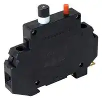
CIRCUIT BREAKER, THERMAL MAGNETIC, 1P, 1
- Manufacturer: WEIDMULLER
- Product type: Thermal Magnetic Circuit Breakers
- CIRCUIT BREAKER, THERMAL MAGNETIC, 1P, 1A; Product Range:CB4200 Series; Current Rating:1A; No. of Poles:1 Pole; Voltage Rating VDC:65VDC; Voltage Rating VAC:250VAC; Circuit Break
- No. of Poles: 1 Pole
- Product Range: CB4200 Series
- Current Rating: 1A
- Voltage Rating VAC: 250V
- Voltage Rating VDC: 65V
- Circuit Breaker Mounting: DIN Rail
| Delivery and price | |
|---|---|
| Units per pack | 250 |
| Price | 41.62 € |
| Current stock | 10+ |
| Lead time | 30 days |
Circuit Protection Solutions **Product Information**

**Contents/Introduction**

Page

## **Branch Rated Circuit Protection**

**==> picture [486 x 36] intentionally omitted <==**

**----- Start of picture text -----**<br>
|||
|---|---|
|9926 Series—AC Version|. . . . . . . . . . . . . . . . . . . . . . . . . . . . . . . . . . . . . . . . . . . . . . . . . . . . . . . . . . . . . . . . . .3|
|9926 Series—AC Version with Auxiliary and Alarm Contacts . . . . . . . . . . . . . . . . . . . . . . . . . . . . . . . . . . . . . . . .4|
|9926 Series—DC Version|. . . . . . . . . . . . . . . . . . . . . . . . . . . . . . . . . . . . . . . . . . . . . . . . . . . . . . . . . . . . . . . . . .5|

**----- End of picture text -----**<br>


## **Supplemental Circuit Protection**

**==> picture [486 x 92] intentionally omitted <==**

**----- Start of picture text -----**<br>
|||
|---|---|
|9926 Series . . . . . . . . . . . . . . . . . . . . . . . . . . . . . . . . . . . . . . . . . . . . . . . . . . . . . . . . . . . . . . . . . . . . . . . . . . . . .6|
|9926 Series with Auxiliary and Alarm Contacts  . . . . . . . . . . . . . . . . . . . . . . . . . . . . . . . . . . . . . . . . . . . . . . . . . .7|
|9926 Series—Ground Fault Current Interrupt|. . . . . . . . . . . . . . . . . . . . . . . . . . . . . . . . . . . . . . . . . . . . . . . . . . .8|
|9926 Series—Mounting Options and Accessories . . . . . . . . . . . . . . . . . . . . . . . . . . . . . . . . . . . . . . . . . . . . . . . .9|
|CB4200 Series|. . . . . . . . . . . . . . . . . . . . . . . . . . . . . . . . . . . . . . . . . . . . . . . . . . . . . . . . . . . . . . . . . . . . . . . . .10|
|CB2200 Series|. . . . . . . . . . . . . . . . . . . . . . . . . . . . . . . . . . . . . . . . . . . . . . . . . . . . . . . . . . . . . . . . . . . . . . . . .12|
|CB9100 Series|. . . . . . . . . . . . . . . . . . . . . . . . . . . . . . . . . . . . . . . . . . . . . . . . . . . . . . . . . . . . . . . . . . . . . . . . .14|

**----- End of picture text -----**<br>


Weidmuller’s DIN-rail mounted circuit breakers are available for use in applications where circuit protection must be able to distinguish between circuit overloads and short circuits. Each circuit breaker has the ability to be reset without the need to change components. All circuit breakers are available with an assortment of jumpers and marking tags.

Circuit breakers in the 9926 Series are UL 489 Listed and CSA Certified as branch rated protection devices under CSA 22.2 No. 5-02. The hydraulic magnetic trip mechanism offers 10,000A of interrupting capacity in 120V and 240V, 50/60Hz applications.

**9926 Series**

The CB2200 Series feature integrated alarm contacts within a narrow profile, thereby allowing increased enclosure capacity. All of these circuit breakers demonstrate consistent reliability through 100% calibration and testing, and feature a touch safe design to prevent injury from accidental contact with live components.

**CB2200 Series**

The CB4200 Series of thermal magnetic circuit breakers feature a pushbutton style of trip reset. This reset provides a visual indication of status which allows for rapid troubleshooting.

**CB4200 Series**

The CB9100 Series of thermal magnetic circuit breakers provide a rugged and industry-standard form factor (18 mm/pole). For supplemental circuit protection.

**CB9100 Series**

**2**

**9926 Series Branch Rated Circuit Breakers–AC Version**

## **Circuit Breakers Hydraulic Magnetic Type**

**==> picture [45 x 18] intentionally omitted <==**

**----- Start of picture text -----**<br>
9926 Series<br>Single Pole<br>**----- End of picture text -----**<br>


**9926 Series**

**Double Pole**

- Single pole and double pole versions

- 120/240 VAC, 50/60 Hz

- Up to 25A

- Just 13 mm wide

- Mounts on 35mm DIN-rail

- UL 489 listed, CSA C22.2 No. 5-02, CE

- VDE

|~~**Ordering Data**~~||~~**Type:  Single Pole**~~|~~**Type:  Single Pole**~~||~~**Type:  Double Pole**~~||
|---|---|---|---|---|---|---|
||**Current Ratings**|**Part No.**||**Current Ratings**|**Part No.**||
||**(amps)**|**TS 35**|**Description**|**(amps)**|**TS 35**|**Description**|
||0.5|**9926251000**|QL-1-13-DM-KM-0.5|0.5|**9926252000**|QL-2-13-DM-KM-0.5|
||1|**9926251001**|QL-1-13-DM-KM-01|1|**9926252001**|QL-2-13-DM-KM-01|
||2|**9926251002**|QL-1-13-DM-KM-02|2|**9926252002**|QL-2-13-DM-KM-02|
||3|**9926251003**|QL-1-13-DM-KM-03|3|**9926252003**|QL-2-13-DM-KM-03|
||4|**9926251004**|QL-1-13-DM-KM-04|4|**9926252004**|QL-2-13-DM-KM-04|
||5|**9926251005**|QL-1-13-DM-KM-05|5|**9926252005**|QL-2-13-DM-KM-05|
||6|**9926251006**|QL-1-13-DM-KM-06|6|**9926252006**|QL-2-13-DM-KM-06|
||7|**9926251007**|QL-1-13-DM-KM-07|7|**9926252007**|QL-2-13-DM-KM-07|
||8|**9926251008**|QL-1-13-DM-KM-08|8|**9926252008**|QL-2-13-DM-KM-08|
||10|**9926251010**|QL-1-13-DM-KM-10|10|**9926252010**|QL-2-13-DM-KM-10|
||13|**9926251013**|QL-1-13-DM-KM-13|13|**9926252013**|QL-2-13-DM-KM-13|
||15|**9926251015**|QL-1-13-DM-KM-15|15|**9926252015**|QL-2-13-DM-KM-15|
||16|**9926251016**|QL-1-13-DM-KM-16|16|**9926252016**|QL-2-13-DM-KM-16|
||20|**9926251020**|QL-1-13-DM-KM-20|20|**9926252020**|QL-2-13-DM-KM-20|
||25|**9926251025**|QL-1-13-DM-KM-25|25|**9926252025**|QL-2-13-DM-KM-25|


|~~**Technical Data**~~||~~**9926 Series AC Version - dimensions in mm (in.)**~~|~~**9926 Series AC Version - dimensions in mm (in.)**~~|~~**9926 Series AC Version - dimensions in mm (in.)**~~||||||||||||||||||||
|---|---|---|---|---|---|---|---|---|---|---|---|---|---|---|---|---|---|---|---|---|---|---|---|
|Voltage<br>120/240 VAC,50/60Hz||||**74**||||||||||||||||||||
|Current||||**(2.91)**||||||||||||||||||||
|minimum<br>0.5A<br>maximum<br>25A<br>Interruptingcapacity<br>10,000A<br>~~TT~~||||**66**<br>**(2.6)**<br>**17.9**<br>**(0.7)**<br>**13**<br>**(0.51)**<br>~~|~~<br>UTE||||~~|~~|~~|~~|~~|~~|**26**<br>**(1.02)**<br>~~|~~<br>e<br>~~i~~<br>~~fi~~|||||||||~~|~~|~~|~~<br>i|~~|~~|~~|~~|
|Dielectric strength<br>1500V,50/60Hz||||||||||||||||||||||||
|Insulation resistance<br>100MM||||**28.5**<br>**(1.12)**||||||||||||||||||||
|Operatinglife<br>10000 mechanical operations<br>Operatingtemperature<br>-40…+65°C||**71.4**<br>**(2.81)**||**57**<br>**(2.24)**<br>**92.8**||**(3.65)**||||||||||||||||||
|Wire size*||||||||||||||||||||||||
|||||||||||||||||||||||||
|0.5-15A:<br>14AWG min.,10AWG max.||||||||||||||||||||||||
|20-25A:<br>10AWG min.<br>Torque<br>20 in.-lb<br>~~sss~~||||**19**<br>**(0.75)**<br>~~=~~|||||||||||**13**<br>0~~0~~|||||||||
|~~**Approval**~~||||**32**<br>**(1.26)**|||||||||||**(0.51)**|||||||||
|UL 489 listed, CSA C22.2 No. 5-02, CE, VDE||||**5**<br>**45**||||||||||||||||||||
|~~**Accessories**~~<br>~~**Part No.**~~||||**(0.2)**<br>**(1.77)**||||||||||||||||||||
|Bus-bar(1pole,insulated,1 m)<br>**67101904**||||**64.8**<br>**(2.55)**||||||||||||||||||||
|Bus-bar(2pole,insulated,1 m)<br>**67101972**<br>Bus-bar end cap,1pole<br>**67101973**||~~**9926 Series–AC version Trip Curve**~~|||||||~~**9926 Series–AC version Trip Curve**~~|||||~~**9926 Series–AC version Trip Curve**~~||||||||||
|Bus-bar end cap,2pole<br>**67101974**<br>Power lug,straight<br>**67101960**<br>Power lug,90°<br>**67101961**<br>Lock-out handle<br>**67101913**<br>*Wire sizes: gauges specified are the minimum allowable as per CSA<br>and UL standards.||**1000**<br>**Minutes**<br>**100**<br>**10**|~~**Operating Characteristics**~~<br>**Curve 1**<br>~~**Ambient Temperature 30°C**~~<br>~~LN~~<br>~~eee~~||||||||||||||**1000**<br>**Minutes**<br>**100**<br>**10**||||||~~**Operating Characteristics**~~<br>**Curve KM**<br>~~**Ambient Temperature 30°C**~~<br>~~LeSe~~|
|||||||||||||||||||||||||
|The 9926 circuit breakers do not have provisions for marking tags.||||||||||||||||||||||||
|**Trip Curves—Hydraulic Magnetic Type**<br>**Typical time/current characteristics at 30ºC**<br>~~**Sample trip characteristics - KM**~~<br>**125% 150% 200% 400% 600% 800% 1000%**<br>minimum<br>15<br>8<br>4<br>0.7<br>0.09<br>0.007<br>0.005<br>(sec)<br>maximum 300<br>90<br>28<br>4<br>1.5<br>0.6<br>0.4<br>A possible solution is to cut the adhesive SchS2 tag rail to length<br>(approximately 20 mm on a single pole unit so the current rating<br>remains visible or approximately 30 mm on a two pole unit).<br>The SchS2 accepts DEK, WS and ESG 8/17 marking tags.<br>The part number for adhesive SchS2 is**1720600000**.<br>~~OO~~<br>~~TT~~<br>~~msn~~||**Tripping Time**<br>**Seconds**<br>**1**<br>**10**<br>**1**<br>**0.1**<br>**0.01**<br>**0.001**|~~Se NE~~<br>~~a~~<br>~~Stee See eee~~<br>~~ee~~<br>~~IRIE eee~~<br>~~a~~<br>~~(i~~<br>~~A~~<br>~~EO~~<br>~~Io~~||||||||||**Tripping Time**||||**Seconds**<br>**1**<br>**10**<br>**1**<br>**0.1**<br>**0.01**<br>**0.001**||||||~~ee~~<br>~~a~~<br>~~pe~~<br>~~pee~~<br>~~a~~<br>~~espe~~<br>~~tl~~<br>~~patNd~~<br>~~SSS SS~~<br>~~== =.———-——~~<br>~~ieee~~<br>~~Oe~~|
|(sec)<br>Although the 9926 series uses a magnetic only trip mechanism, CSA<br>testing indicates a trip characteristic similar to thermal magnetic trip||**100**<br>**105**<br>**130**<br>**150**<br>**200**<br>**300**<br>**400**<br>**500**<br>**1000**<br>**1500**<br>**2000**<br>**2500**<br>**3000**<br>**4000**<br>**5000**<br>**(%) Rated Current**|||||||||||||||||||**100**||**105**<br>**125**<br>**150**<br>**200**<br>**300**<br>**400**<br>**500**<br>**1000**<br>**1500**<br>**2000**<br>**2500**<br>**3000**<br>**4000**<br>**5000**<br>**(%) Rated Current**|
|mechanisms. No de-rating is required at elevated temperatures.||Trip Curve 1 applies to the following part numbers where||||||||||||||||||||||
|Additional trip curves and amp ratings are available||"XX" is the current rating:||"XX" is the current rating:||||||||||||||||||||
|upon request.||Single Pole—||Single Pole—**99262512XX**<br>Double Pole—**99262522XX**||||||||||||||||||||


~~**Sample trip characteristics - KM**~~ **125% 150% 200% 400% 600% 800% 1000%** minimum 15 8 4 0.7 0.09 0.007 0.005 ~~OO~~ (sec) ~~TT msn~~ maximum 300 90 28 4 1.5 0.6 0.4 (sec) Although the 9926 series uses a magnetic only trip mechanism, CSA testing indicates a trip characteristic similar to thermal magnetic trip mechanisms. No de-rating is required at elevated temperatures.

Additional trip curves and amp ratings are available upon request.

**3**

**9926 Series Branch Rated Circuit Breakers–AC Version with Contacts**

## **Circuit Breakers with Auxiliary switch, Trip alarm, Combination of both**

## **9926 Series**

**Single Pole w/ Auxiliary Contact**

**9926 Series Single Pole Trip (Alarm Contact)**

**9926 Series Single Pole Combination (Auxiliary & Alarm Contact)**

- AC voltages (120/240V)

- Single and double pole versions

- UL 489 and CSA listed

- Factory fitted auxiliary or trip alarm

- Compact 6.5mm width

- Attached to right hand side of circuit breaker

## ~~**Technical Data**~~

|Voltage|120/240 VAC,50/60Hz|120/240 VAC,50/60Hz|
|---|---|---|
|Current|||
|minimum||0.5A|
|maximum||25A|
|Interruptingcapacity||10,000A|
|Dielectric strength||1500V,50/60Hz|
|Insulation resistance||100MM|
|Operating life||10000|
|||mechanical operations|
|Operatingtemperature||-40…+65°C|
|Wire size*|||
|0.5-15A:|14AWG min.,10AWG max.||
|20-25A:||10AWG min.|
|Torque||20 in.-lb|
|~~**Approval**~~|||


## ~~**Type:  Single Pole Aux**~~

## **Current**

**Ratings**

|**(amps)**|**Part No.**|**Description**|
|---|---|---|
|1|**9926261001**|QL-A-1-13-DM-KM-1|
|2|**9926261002**|QL-A-1-13-DM-KM-2|
|5|**9926261005**|QL-A-1-13-DM-KM-5|
|10|**9926261010**|QL-A-1-13-DM-KM-10|
|15|**9926261015**|QL-A-1-13-DM-KM-15|
|20|**9926261020**|QL-A-1-13-DM-KM-20|
|25|**9926261025**|QL-A-1-13-DM-KM-25|


## **9926 Series**

**Double Pole w/ Auxiliary Contact**

~~**Type:  Single Pole Combo**~~

~~**Type:  Single Pole Trip**~~

**Current**

**Current**

**Ratings**

**Ratings**

|**(amps)**|**Part No.**|**Description**|**(amps)**|**Part No.**|**Description**|
|---|---|---|---|---|---|
|1|**9926271001**|QL-T-1-13-DM-KM-1|1|**9926281001**|QL-AT-1-13-DM-KM-1|
|2|**9926271002**|QL-T-1-13-DM-KM-2|2|**9926281002**|QL-AT-1-13-DM-KM-2|
|5|**9926271005**|QL-T-1-13-DM-KM-5|5|**9926281005**|QL-AT-1-13-DM-KM-5|
|10|**9926271010**|QL-T-1-13-DM-KM-10|10|**9926281010**|QL-AT-1-13-DM-KM-10|
|15|**9926271015**|QL-T-1-13-DM-KM-15|15|**9926281015**|QL-AT-1-13-DM-KM-15|
|20|**9926271020**|QL-T-1-13-DM-KM-20|20|**9926281020**|QL-AT-1-13-DM-KM-20|
|25|**9926271025**|QL-T-1-13-DM-KM-25|25|**9926281025**|QL-AT-1-13-DM-KM-25|


**9926 Series Double Pole Combination (Auxiliary & Alarm Contact)**

## **9926 Series Double Pole Trip (Alarm Contact)**

UL 489 listed, CSA C22.2 No. 5-02, CE, VDE

- *Wire sizes: gauges specified are the minimum allowable as per CSA and UL standards.

- The 9926 circuit breakers do not have provisions for marking tags. A possible solution is to cut the adhesive SchS2 tag rail to length (approximately 20 mm on a single pole unit so the current rating remains visible or approximately 30 mm on a two pole unit). The SchS2 accepts DEK, WS and ESG 8/17 marking tags. The part number for adhesive SchS2 is **1720600000** .

~~**Type:  Double Pole Aux**~~

**Current**

**Ratings**

- **(amps) Part No. Description** 1 **9926262001** QL-A-2-13-DM-KM-1 2 **9926262002** QL-A-2-13-DM-KM-2 5 **9926262005** QL-A-2-13-DM-KM-5 10 **9926262010** QL-A-2-13-DM-KM-10 15 **9926262015** QL-A-2-13-DM-KM-15 20 **9926262020** QL-A-2-13-DM-KM-20 25 **9926262025** QL-A-2-13-DM-KM-25

~~**Type:  Double Pole Combo**~~

~~**Type:  Double Pole Trip**~~

**Current**

**Current**

**Ratings**

**Ratings**

**(amps) Part No. Description (amps) Part No. Description** 1 **9926272001** QL-T-2-13-DM-KM-1 1 **9926282001** QL-AT-2-13-DM-KM-1 2 **9926272002** QL-T-2-13-DM-KM-2 2 **9926282002** QL-AT-2-13-DM-KM-2 5 **9926272005** QL-T-2-13-DM-KM-5 5 **9926282005** QL-AT-2-13-DM-KM-5 10 **9926272010** QL-T-2-13-DM-KM-10 10 **9926282010** QL-AT-2-13-DM-KM-10 15 **9926272015** QL-T-2-13-DM-KM-15 15 **9926282015** QL-AT-2-13-DM-KM-15 20 **9926272020** QL-T-2-13-DM-KM-20 20 **9926282020** QL-AT-2-13-DM-KM-20 25 **9926272025** QL-T-2-13-DM-KM-25 25 **9926282025** QL-AT-2-13-DM-KM-25

~~**9926 Series–AC version Trip Curve**~~

~~**Dual Mount Dimensions in mm (in.)**~~

**==> picture [447 x 168] intentionally omitted <==**

**----- Start of picture text -----**<br>
Trip Curves—HydraulicMagnetic Type Typical time/current characteristics  1000100 Ambient TemOperating Characteristics Curve KM perature 30°C (1.03)26.2 (1.23)31.3 (0.83)21.1 TRIP ALARM Q. CONNECTORS<br>at 30ºC 5.5<br>10 (0.22)<br>Additional trip curves and  Se (uty a] a n<br>amp ratings are available  1<br>SSReScotteoeeee oe | @ t tr<br>upon request.<br>10<br>AUX SWITCH Q. CONNECTORS<br>1<br>7<br>0.1 (0.28)<br>10.7<br>0.01 (0.84)21.3 32.9 (0.42)<br>(1.3)<br>0.001 ine<br>(%) Rated Current<br>2<br>Minutes (0.08)<br>(N/O)16 (N/C)18 (C)15<br>0.5 (0.02)<br>57.0 (2.24)<br>Tripping Time<br>11(C) 12(N/C) 14(N/O)<br>2.8 (0.11)<br>Seconds<br>0.5 (0.02)<br>100105 125 150 200 300 400 500 1000 1500 2000 2500 3000 4000 5000<br>**----- End of picture text -----**<br>


**4**

**9926 Series Branch Rated Circuit Breakers–DC Version**

## **Circuit Breakers Hydraulic Magnetic Type**

## **9926 Series 9926 Series Single Pole Single Pole (80 VDC) (125 VDC)**

- Single pole versions only

- U2 trip curve for general purpose applications

- 80 and 125 VDC

- Up to 60A

- Just 13 mm wide

- Mounts on 35mm DIN-rail

- UL 489A listed

- VDE

|~~**Ordering Data**~~|~~**Type:  Single Pole (80 VDC)**~~|~~**Type:  Single Pole (80 VDC)**~~|~~**Type:  Single Pole (80 VDC)**~~|
|---|---|---|---|
||**Current**|||
||**Ratings**|||
||**(amps)**|**Part No.**|**Description**|
||0.5|**9926251900**|QY-1-13-DM-U2-0.5|
||1|**9926251901**|QY-1-13-DM-U2-01|
||2|**9926251902**|QY-1-13-DM-U2-02|
||3|**9926251903**|QY-1-13-DM-U2-03|
||4|**9926251904**|QY-1-13-DM-U2-04|
||5|**9926251905**|QY-1-13-DM-U2-05|
||10|**9926251910**|QY-1-13-DM-U2-10|
||15|**9926251915**|QY-1-13-DM-U2-15|
||20|**9926251920**|QY-1-13-DM-U2-20|
||25|**9926251925**|QY-1-13-DM-U2-25|
||30|**9926251930**|QY-1-13-DM-U2-30|
||35|**9926251935**|QY-1-13-DM-U2-35|
||40|**9926251940**|QY-1-13-DM-U2-40|
||45|**9926251945**|QY-1-13-DM-U2-45|
||50|**9926251950**|QY-1-13-DM-U2-50|
||60|**9926251960**|QY-1-13-DM-U2-60|


|~~**Type:  Single Pole (125 VDC)**~~|~~**Type:  Single Pole (125 VDC)**~~|~~**Type:  Single Pole (125 VDC)**~~|
|---|---|---|
|**Current**|||
|**Ratings**|||
|**(amps)**|**Part No.**|**Description**|
|1|**9926251801**|QY-1-13-DM-U2-01-B1|
|2|**9926251802**|QY-1-13-DM-U2-02-B1|
|3|**9926251803**|QY-1-13-DM-U2-03-B1|
|4|**9926251804**|QY-1-13-DM-U2-04-B1|
|5|**9926251805**|QY-1-13-DM-U2-05-B1|
|10|**9926251810**|QY-1-13-DM-U2-10-B1|
|15|**9926251815**|QY-1-13-DM-U2-15-B1|
|20|**9926251820**|QY-1-13-DM-U2-20-B1|
|25|**9926251825**|QY-1-13-DM-U2-25-B1|
|30|**9926251830**|QY-1-13-DM-U2-30-B1|
|35|**9926251835**|QY-1-13-DM-U2-35-B1|
|40|**9926251840**|QY-1-13-DM-U2-40-B1|
|45|**9926251845**|QY-1-13-DM-U2-45-B1|
|50|**9926251850**|QY-1-13-DM-U2-50-B1|
|60|**9926251860**|QY-1-13-DM-U2-60-B1|


## **Accessories**

~~**9926 Series–DC version Trip Curve**~~

## ~~**Dimensions in mm (in.)**~~

**Trip Curves—Hydraulic Magnetic Type Typical time/current characteristics time/current characteristics at 30ºC**

|~~**Type**~~<br>Bus-bar(1pole,insulated 1m)<br>Bus bar end cap,1pole<br>Power lug,straight|~~**Part No.**~~<br>**67101904**<br>**67101973**<br>**67101960**|
|---|---|
|Power lug,90°<br>Lock-out handle|**67101961**<br>**67101913**|


**==> picture [461 x 211] intentionally omitted <==**

**----- Start of picture text -----**<br>
Bus-bar (1 pole, insulated 1m) 67101904 Magnetic Type Typical time/current characteristics  (2.91)74<br>Bus bar end cap, 1 pole 67101973 at 30ºC 66 13<br>Power lug, straight 67101960 (2.6) (0.51)<br>Power lug, 90° 67101961 Additional trip curves and amp ratings<br>Lock-out handle 67101913 are available upon request.<br>1000<br>Operating Characteristics<br>Technical Data i Curve U2 DC<br>Voltage 80,125 VDC 100 (i (4% Ripple Factor) lq “<br>Current a [SPS =F Ambient Temperature 30°C<br>10<br>minimum 0.5 A<br>maximum 60 A BS |<br>BE 1<br>Interrupting capacity 10,000 A a l e<br>HOH Dielectric strenInsulation resistgathnce 1500 V, 50/60 Hz100 MM 10 ee[SeHot NESes tt tt ttt a (0.75)19 |<br>Operating lifeOpe Re rating temperature mechanical o-40p…+erations10000 65°C 0.11 (inet! Sone 5 (1.26)32 45<br>Wire size*1-15A: 14 AWG min.,  Se (0.2) (1.77)<br>10 AWG max. 0.01 a ee 64.8<br>(2.55)<br>20-25A: 10 AWG min.<br>OO Torque 20 in.-lb 0.001 SSS (i ttt TPSSS<br>Approval<br>UL 489A Listed, CE, VDE (%) Rated Current<br>17.9 (0.7)<br>28.5 (1.12)<br>Minutes 71.4 (2.81) 57 (2.24) 92.8 (3.65)<br>Tripping Time<br>Seconds<br>100105 130 150 200 300 400 500 1000 1500 2000 2500 3000 4000 5000<br>**----- End of picture text -----**<br>


*Wire sizes: gauges specified are the minimum allowable as per CSA and UL standards.

The 9926 circuit breakers do not have provisions for marking tags. A possible solution is to cut the adhesive SchS2 tag rail to length (approximately 20 mm on a single pole unit so the current rating remains visible or approximately 30 mm on a two pole unit). The SchS2 accepts DEK, WS and ESG 8/17 marking tags. The part number for adhesive SchS2 is **1720600000.**

**5**

## **9926 Series Supplemental Circuit Breakers**

## **Circuit Breakers Hydraulic Magnetic Type**

**9926 Series Single Pole**

**9926 Series Double Pole**

**9926 Series Triple Pole**

- AC Voltages 240/480V

- Trip curve 2 for general purpose applications

- UL 1077 recognized

- VDE, CSA, and CE Approved

- Just 13 mm wide

- Mounts to 35 mm DIN-rail

- Factory fitted auxiliary or trip alarm

- Single, double and triple pole versions

|~~**Ordering Data**~~|||~~**Type:  Single Pole**~~|~~**Type:  Single Pole**~~||~~**Type:  Double Pole**~~|~~**Type:  Double Pole**~~||~~**Type:  Triple Pole**~~|~~**Type:  Triple Pole**~~|
|---|---|---|---|---|---|---|---|---|---|---|
|||**Current**|||**Current**|||**Current**|||
|||**Ratings**|||**Rating**|||**Rating**|||
|||**(amps)**|**Part No.**|**Description**|**(amps)**|**Part No.**|**Description**|**(amps)**|**Part No.**|**Description**|
|||1|**9926251501**|QZ-1-13-D-2-01|1|**9926252501**|QZ-2-13-D-2-01|10|**9926253510**|QZ-3-13-D-2-10|
|||2|**9926251502**|QZ-1-13-D-2-02|2|**9926252502**|QZ-2-13-D-2-02|15|**9926253515**|QZ-3-13-D-2-15|
|||3|**9926251503**|QZ-1-13-D-2-03|4|**9926252504**|QZ-2-13-D-2-04|20|**9926253520**|QZ-3-13-D-2-20|
|||4|**9926251504**|QZ-1-13-D-2-04|5|**9926252505**|QZ-2-13-D-2-05|25|**9926253525**|QZ-3-13-D-2-25|
|||5|**9926251505**|QZ-1-13-D-2-05|6|**9926252506**|QZ-2-13-D-2-06|30|**9926253530**|QZ-3-13-D-2-30|
|||6|**9926251506**|QZ-1-13-D-2-06|10|**9926252510**|QZ-2-13-D-2-10|40|**9926253540**|QZ-3-13-D-2-40|
|||8|**9926251508**|QZ-1-13-D-2-08|15|**9926252515**|QZ-2-13-D-2-15|50|**9926253550**|QZ-3-13-D-2-50|
|||10|**9926251510**|QZ-1-13-D-2-10|20|**9926252520**|QZ-2-13-D-2-20|60|**9926253560**|QZ-3-13-D-2-60|
|||15|**9926251515**|QZ-1-13-D-2-15|25|**9926252525**|QZ-2-13-D-2-25||||
|||20|**9926251520**|QZ-1-13-D-2-20|30|**9926252530**|QZ-2-13-D-2-30||||
|||25|**9926251525**|QZ-1-13-D-2-25|35|**9926252535**|QZ-2-13-D-2-35||||
|||35|**9926251535**|QZ-1-13-D-2-35|40|**9926252540**|QZ-2-13-D-2-40||||
|||40|**9926251540**|QZ-1-13-D-2-40|50|**9926252550**|QZ-2-13-D-2-50||||
|||50|**9926251550**|QZ-1-13-D-2-50|60|**9926252560**|QZ-2-13-D-2-60||||
|||60|**9926251560**|QZ-1-13-D-2-60|||||||


## **Accessories**

~~**9926 Series Supplemental – dimensions in mm (in.)**~~

|~~**Type**~~|~~**Part No.**~~||||||**65**||||||||||||||||||||||||||
|---|---|---|---|---|---|---|---|---|---|---|---|---|---|---|---|---|---|---|---|---|---|---|---|---|---|---|---|---|---|---|---|---|
|Bus bar(1pole,insulated 1m)|**67101904**||||||**(2.56)**||||||||||||||||||||||||||
|Bus bar(2pole,insulated 1m)<br>Bus bar(3pole,insulated 1m)|**67101972**<br>**67101971**||||||**60**<br>**(2.36)**|||||**13**<br>**(0.51)**||||||**26**<br>**(1.02)**||||||||||**39**<br>**(1.54)**|||||
|Bus bar end cap,1pole<br>Bus bar end cap,2pole or 3pole|**67101973**<br>**67101974**||**22.5**||**(0.86)**|||||**25.9**<br>**(0.94)**|||||||||||||||||||||||
|Power lug,straight|**67101960**||||||||||||||||||||||||||||||||
|Power lug,90°<br>**67101961**<br>Lock-out handle<br>**67101913**<br>~~Tt~~||||||||||**45**<br>**(1.77)**||**92.8**<br>**(3.65)**||||ft)|||||||||ULL|ULL|ULL|ULL|ULL|ULL|ULL|ULL|
||||||||||||||||||||||||||||||||||
||||||||||||||||||||||||||||||||||
||||||||||||||||||||||||||||||||||
||||**5.0**<br>**(0.2)**|-|||**44**<br>**(1.73)**<br>**63.8**<br>**(2.51)**<br>**73**|||||||||**13**<br>**(0.51)**<br>IL|||||||||**13**<br>**(0.51)**<br>IL||||||||
||||||||**(2.87)**||||||||||||||||||||||||||
|~~**Technical Data**~~||||||||||||~~**9926 Series–Supplemental Trip Curve**~~|||||||||||||||||||||
|Voltage<br>Current<br>minimum<br>maximum<br>Interruptingcapacity<br>Dielectric strength<br>Insulation resistance<br>Operatinglife<br>Operatingtemperature<br>Wire size*<br>1-15A:|||277/480 VAC @ 50/60 Hz<br>0.5 A<br>60 A<br>5 kA @ 277/480 V,5 kA @ 120 V,5 kA @ 240 V<br>1500 V,50/60 Hz<br>100 MM<br>10000 mechanical operations<br>-40…+65°C<br>14 AWG min.,10 AWG max.|||||||||**Tripping Time**<br>Additional trip curves and<br>amp ratings are available<br>upon request.<br>**Trip Curves—Hydraulic**<br>**Magnetic Type Typical**<br>**time/current characteristics**<br>**at 30ºC**||||||||||||**1000**<br>**Minutes**<br>**100**<br>**10**<br>**1**<br>**10**<br>**1**|||||||||
|20-25A:<br>Torque<br>~~**Approval**~~||||||||||10 AWG min.<br>20 in.-lb||||||||||||||**Seconds**|**0.1**||||||||
|UL 1077 Recognized,VDE(EN 60947-2),CSA C22.2 No. 235||CSA C22.2 No. 235,CE Approved||||||||||||||||||||||**0.01**|||||||||


**==> picture [249 x 174] intentionally omitted <==**

**----- Start of picture text -----**<br>
9926 Series–Supplemental Trip Curve<br>Trip Curves—Hydraulic 1000 Operating Characteristics<br>Magnetic Type Typical  Curve 2<br>time/current characteristics  100<br>at 30ºC Ambient Temperature 30°C<br>Additional trip curves and  10<br>amp ratings are available<br>upon request. 1<br>10<br>1<br>0.1<br>0.01<br>0.001<br>(%) Rated Current<br>Minutes<br>Tripping Time<br>Seconds<br>100105 130 150 200 300 400 500 1000 1500 2000 2500 3000 4000 5000<br>**----- End of picture text -----**<br>


*Wire sizes: gauges specified are the minimum allowable as per CSA and UL standards.

- The 9926 circuit breakers do not have provisions for marking tags. A possible solution is to cut the adhesive SchS2 tag rail to length (approximately 20 mm on a single pole unit so the current rating remains visible or approximately 30 mm on a two pole unit).The SchS2 accepts DEK, WS and ESG 8/17 marking tags. The part number for adhesive SchS2 is **1720600000** .

**6**

## **9926 Series Supplemental Circuit Breakers with Contacts**

## **Circuit Breakers Auxiliary switch, Trip alarm, Combination of both**

## **9926 Series Single Pole w/ Auxiliary Contact**

## **9926 Series 9926 Series Single Pole Trip Single Pole Combination (Alarm Contact) (Auxiliary & Alarm Contact)**

- AC Voltages 240/480V

- Trip curve 2 for general purpose applications

- UL 1077 recognized

- VDE, CSA, and CE Approved

- Just 13 mm wide

- Mounts to 35 mm DIN-rail

- Factory fitted auxiliary or trip alarm

- Single, double and triple pole versions

|~~**Technical Data**~~||||
|---|---|---|---|
|Voltage||277/480 VAC @ 50/60 Hz||
|Current||||
|minimum|||0.5 A|
|maximum|||60 A|
|Interrupting capacity|||5 kA @ 277/480 V,|
||5 kA @ 120 V||5 kA @ 120 V,5 kA @ 240 V|
|Dielectric strength|||1500 V,50/60 Hz|
|Insulation resistance|||100 MM|
|Operating life|||10000|
||||mechanical operations|
|Operatingtemperature|||-40…+65°C|
|Wire size*||||
|1-15A:|14 AWG min.|14 AWG min.,10 AWG max.||
|20-25A:|||10 AWG min.|
|Torque|||20 in.-lb|


~~**Approval**~~ UL 1077 Recognized, VDE (EN 60947-2), CSA C22.2 No. 235, CE Approved

||~~**Type:  Single Pole Aux**~~|~~**Type:  Single Pole Aux**~~|||~~**Type:  Single Pole Trip**~~|~~**Type:  Single Pole Trip**~~|||~~**Type:  Single  Pole Combo**~~|~~**Type:  Single  Pole Combo**~~|
|---|---|---|---|---|---|---|---|---|---|---|
|**Current**|**Current**|||**Current**|**Current**|||**Current**|**Current**||
|**Ratings**||||**Ratings**||||**Ratings**|||
|**(amps)**|**Part No.**|**Description**||**(amps)**|**Part No.**|**Description**||**(amps)**|**Part No.**|**Description**|
|1|**9926261501**|QZ-A-1-13-D-2-01||1|**9926271501**|QZ-T-1-13-D-2-01||1|**9926281501**|QZ-AT-1-13-D-2-01|
|2|**9926261502**|QZ-A-1-13-D-2-02||2|**9926271502**|QZ-T-1-13-D-2-02||2|**9926281502**|QZ-AT-1-13-D-2-02|
|5|**9926261505**|QZ-A-1-13-D-2-05||5|**9926271505**|QZ-T-1-13-D-2-05||5|**9926281505**|QZ-AT-1-13-D-2-05|
|10|**9926261510**|QZ-A-1-13-D-2-10||10|**9926271510**|QZ-T-1-13-D-2-10||10|**9926281510**|QZ-AT-1-13-D-2-10|
|15|**9926261515**|QZ-A-1-13-D-2-15||15|**9926271515**|QZ-T-1-13-D-2-15||15|**9926281515**|QZ-AT-1-13-D-2-15|
|20|**9926261520**|QZ-A-1-13-D-2-20||20|**9926271520**|QZ-T-1-13-D-2-20||20|**9926281520**|QZ-AT-1-13-D-2-20|
|25|**9926261525**|QZ-A-1-13-D-2-25||25|**9926271525**|QZ-T-1-13-D-2-25||25|**9926281525**|QZ-AT-1-13-D-2-25|


## **9926 Series**

## **9926 Series**

## **9926 Series**

**Double Pole Combination (Auxiliary & Alarm Contact)**

**Double Pole Trip (Alarm Contact)**

**Double Pole w/ Auxiliary Contact**

*Wire sizes: gauges specified are the minimum allowable as per CSA and UL standards.

The 9926 circuit breakers do not have provisions for marking tags. A possible solution is to cut the adhesive SchS2 tag rail to length (approximately 20 mm on a single pole unit so the current rating remains visible or approximately 30 mm on a two pole unit). The SchS2 accepts DEK, WS and ESG 8/17 marking tags.The part number for adhesive SchS2 is **1720600000** .

~~**9926 Series–Supplemental Trip Curve**~~

**Trip Curves—Hydraulic Magnetic Type Typical time/current characteristics at 30ºC**

**==> picture [133 x 168] intentionally omitted <==**

**----- Start of picture text -----**<br>
1000<br>Operating Characteristics<br>Curve 2<br>100<br>Ambient Temperature 30°C<br>10<br>1 Serr ire<br>10<br>1<br>0.1<br>a<br>0.01 eevee<br>0.001<br>(%) Rated Current<br>Minutes<br>Tripping Time<br>Seconds<br>100105 130 150 200 300 400 500 1000 1500 2000 2500 3000 4000 5000<br>**----- End of picture text -----**<br>


||~~**Type:  Double Pole Aux**~~|~~**Type:  Double Pole Aux**~~|||~~**Type:  Double Pole Trip**~~|~~**Type:  Double Pole Trip**~~|||~~**Type:  Double Pole Combo**~~|~~**Type:  Double Pole Combo**~~|
|---|---|---|---|---|---|---|---|---|---|---|
|**Current**|**Current**|||**Current**|**Current**|||**Current**|||
|**Ratings**||||**Ratings**||||**Ratings**|||
|**(amps)**|**Part No.**|**Description**||**(amps)**|**Part No.**|**Description**||**(amps)**|**Part No.**|**Description**|
|1|**9926262501**|QZ-A-2-13-D-2-01||1|**9926272501**|QZ-T-2-13-D-2-01||1|**9926282501**|QZ-AT-2-13-D-2-01|
|2|**9926262502**|QZ-A-2-13-D-2-02||2|**9926272502**|QZ-T-2-13-D-2-02||2|**9926282502**|QZ-AT-2-13-D-2-02|
|5|**9926262505**|QZ-A-2-13-D-2-05||5|**9926272505**|QZ-T-2-13-D-2-05||5|**9926282505**|QZ-AT-2-13-D-2-05|
|10|**9926262510**|QZ-A-2-13-D-2-10||10|**9926272510**|QZ-T-2-13-D-2-10||10|**9926282510**|QZ-AT-2-13-D-2-10|
|15|**9926262515**|QZ-A-2-13-D-2-15||15|**9926272515**|QZ-T-2-13-D-2-15||15|**9926282515**|QZ-AT-2-13-D-2-15|
|20|**9926262520**|QZ-A-2-13-D-2-20||20|**9926272520**|QZ-T-2-13-D-2-20||20|**9926282520**|QZ-AT-2-13-D-2-20|
|25|**9926262525**|QZ-A-2-13-D-2-25||25|**9926272525**|QZ-T-2-13-D-2-25||25|**9926282525**|QZ-AT-2-13-D-2-25|


**9926 Series 9926 Series 9926 Series Triple Pole Triple Pole Trip Triple Pole Combination w/ Auxiliary Contact ( Alarm Contact) (Auxiliary & Alarm Contact)**

||~~**Type:  Triple Pole Aux**~~|~~**Type:  Triple Pole Aux**~~|||~~**Type:  Triple Pole Trip**~~|~~**Type:  Triple Pole Trip**~~|||~~**Type:  Triple Pole Combo**~~|~~**Type:  Triple Pole Combo**~~|
|---|---|---|---|---|---|---|---|---|---|---|
|**Current**|**Current**|||**Current**|**Current**|||**Current**|**Current**||
|**Ratings**||||**Ratings**||||**Ratings**|||
|**(amps)**|**Part No.**|**Description**||**(amps)**|**Part No.**|**Description**||**(amps)**|**Part No.**|**Description**|
|1|**9926263501**|QZ-A-3-13-D-2-01||1|**9926273501**|QZ-T-3-13-D-2-01||1|**9926283501**|QZ-AT-3-13-D-2-01|
|2|**9926263502**|QZ-A-3-13-D-2-02||2|**9926273502**|QZ-T-3-13-D-2-02||2|**9926283502**|QZ-AT-3-13-D-2-02|
|5|**9926263505**|QZ-A-3-13-D-2-05||5|**9926273505**|QZ-T-3-13-D-2-05||5|**9926283505**|QZ-AT-3-13-D-2-05|
|10|**9926263510**|QZ-A-3-13-D-2-10||10|**9926273510**|QZ-T-3-13-D-2-10||10|**9926283510**|QZ-AT-3-13-D-2-10|
|15|**9926263515**|QZ-A-3-13-D-2-15||15|**9926273515**|QZ-T-3-13-D-2-15||15|**9926283515**|QZ-AT-3-13-D-2-15|
|20|**9926263520**|QZ-A-3-13-D-2-20||20|**9926273520**|QZ-T-3-13-D-2-20||20|**9926283520**|QZ-AT-3-13-D-2-20|
|25|**9926263525**|QZ-A-3-13-D-2-25||25|**9926273525**|QZ-T-3-13-D-2-25||25|**9926283525**|QZ-AT-3-13-D-2-25|


**7**

## **9926 Series Supplemental Circuit Breakers–GFCI**

## **Ground Fault Current Interrupt**

## **9926 Series GFCI**

- CE approved

- UL1077 and UL1053 recognized

- Small frame size (26mm wide)

- Single pole plus switched neutral earth leakage protection

- Trip point is unaffected by ambient temperature

- Current ratings up to 50A

- Trip indication (mid trip handle position)

- Trip curve 2 for general purpose applications

**==> picture [41 x 7] intentionally omitted <==**

**----- Start of picture text -----**<br>
Ordering Data<br>**----- End of picture text -----**<br>


**==> picture [119 x 7] intentionally omitted <==**

**----- Start of picture text -----**<br>
9926 Series GFCI – dimensions in mm (in.)<br>**----- End of picture text -----**<br>


||~~**Type:  Single Pole GFCI**~~|~~**Type:  Single Pole GFCI**~~|
|---|---|---|
|**Current**|**Current**||
|**Ratings**|||
|**(amps)**<br>5<br>10|**Part No.**<br>**9926291105**<br>**9926291110**|**Description**<br>QF17A2505 - CB W/GFI<br>QF17A2510 - CB W/GFI|
|15|**9926291115**|QF17A2515 - CB W/GFI|
|20|**9926291120**|QF17A2520 - CB W/GFI|
|25|**9926291125**|QF17A2525 - CB W/GFI|
|30<br>50|**9926291130**<br>**9926291150**|QF17A2530 - CB W/GFI<br>QF17A2550 - CB W/GFI|


**==> picture [518 x 340] intentionally omitted <==**

**----- Start of picture text -----**<br>
5 9926291105 QF17A2505 - CB W/GFI 73<br>(2.87)<br>10 9926291110 QF17A2510 - CB W/GFI 65<br>15 9926291115 QF17A2515 - CB W/GFI (2.56)<br>20 9926291120 QF17A2520 - CB W/GFI<br>25 9926291125 QF17A2525 - CB W/GFI<br>30 9926291130 QF17A2530 - CB W/GFI<br>OO 50 9926291150 QF17A2550 - CB W/GFI OWES<br>Technical Data 9926 Series–AC version Trip Curve<br>TT Standard AmSensitivitNumber of Polesy (mAp)ere Ratings (A) 30 (CE) / 22 5 to 50A1 + N(UL) Trip Curves—Hydraulic MagneticType Typical  O O p <! b<br>time/current characteristics<br>Equipment Type Earth Leakage/GFCS at 30ºC<br>Rated Voltage (V) 230 (CE) / 240 (UL)<br>OO Rated Interrupting/ 5 kA :<br>Withstand Capacity (kA) – 1000<br>a === Operating Characteristics O TUBB Jeep<br>Weight (kg) 0.26 fot} fF +t Curve 2 =<br>Trip Curve (standard) 2 100 Eo<br>Operating Temperature -40 to +65ºC Ambient Temperature 30°C (1.73)44<br>10<br>Approval 68.8<br>(2.71)<br>ER UL 1077 and UL 1053, CE E 1 EEE<br>ee<br>10 RSS Cer|<br>26<br>(1.02)<br>1 Sea<br>0.1 (iczsoes] toes HOTOH-- _<br>16.4 8.0<br>(0.646) (0.315)<br>0.01<br>eee ra<br>0.001 So lini ini] — SS<br>PA EE HU {| | este<br>(%) Rated Current =|] fet<br>35.7<br>(1.406)<br>yj |<br>93 (3.66) 82.4 (3.24) 57(2.24)<br>Minutes<br>Tripping Time<br>Seconds<br>7.8 (0.307)<br>100105 130 150 200 300 400 500 1000 1500 2000 2500 3000 4000 5000 71.4 (2.81) 26 (1.02)<br>**----- End of picture text -----**<br>


**8**

**9926 Series Mounting Options and Accessories**

## **Mounting Options**

If the product is not vertically mounted in the normal DIN-rail mounting orientation, a rating factor must be applied. Figure 1 shows a diagram of the rating factor to apply. The published curves for these circuit breaker products are produced with the circuit breaker in the vertical mounting position. The rating factor only applies to the must hold and must trip points of the curve as the other parts (instantaneous trip point) stay largely unaffected.

It is important to note that in environments that are exposed to a high degree of vibration, the cables that connect to the circuit breaker must be securely held in place, as the breaker is not designed to carry the weight of the cables. A maximum of 35N can be applied to the terminal area, in a direction perpendicular to the mounting axis.

**==> picture [213 x 213] intentionally omitted <==**

**----- Start of picture text -----**<br>
3<br>R<br>9 %<br>O I<br>FF O<br>H<br>N<br>Z<br>O<br>N O<br>P 4<br>O FF<br>U 5<br>5% 95%<br>5 U<br>9<br>F<br>F O<br>4 P<br>O N<br>N O<br>O F<br>T<br>F<br>% V<br>R<br>1<br>0 E 0<br>0 E R 0<br>1 %<br>F O<br>V<br>F<br>T<br>O N<br>N<br>O<br>D<br>NO FF<br>W O<br>1<br>5 4<br>% 0<br>4<br>5<br>5<br>5<br>O W<br>0 %<br>1<br>FF O<br>D N<br>O N<br>N O<br>Z H<br>O F<br>I<br>F<br>01<br>RO<br>%7<br>**----- End of picture text -----**<br>


## **Accessories**

|~~**Technical Data**~~<br>Current Rating|80A max.|
|---|---|
|Voltage|500V max.|
|Short Circuit Strength|25kA|
|||
|~~**Type**~~|~~**Part No.**~~|
|Bus bar(1pole,insulated 1m)|**67101904**|
|Bus bar(2pole,insulated 1m)|**67101972**|
|Bus bar(3pole,insulated 1m)|**67101971**|


|~~**Type**~~|~~**Part No.**~~|
|---|---|
|Bus bar end cap,1pole|**67101973**|
|Bus bar end cap,2pole or 3pole|**67101974**|


## ~~**Part Number Table - Example**~~

To order 9926 Series Single Pole Circuit Breaker

Part No. 9926251100

- Current Rating of 1.0 amp

- Internal Resistance per Pole of 1.1 ohms

- Trip Curve – M1, Medium (Standard)

## **9 9 2 6 2 5 1 0 0 0**

**==> picture [33 x 55] intentionally omitted <==**

**----- Start of picture text -----**<br>
Amperage<br>"00" - 0.5A<br>"01" - 1A<br>"02" - 2A<br>        /<br>"60" - 60A<br>Trip Curves<br>**----- End of picture text -----**<br>


**==> picture [95 x 57] intentionally omitted <==**

**----- Start of picture text -----**<br>
"0" - Branch AC KM (Standard)<br>"1" - Branch AC OP (Instantaneous)<br>"2" - Branch AC 1 (Fast)<br>"4" - Branch 80VDC 1 (Fast)<br>"5" - Supplemental 2 (Standard)<br>"6" - Branch 125VDC OP (Instantaneous)<br>"7" - Branch 80VDC OP (Instantaneous)<br>"8" - Branch 125VDC U2 (Standard)<br>"9" - Branch 80VDC U2 (Standard)<br>**----- End of picture text -----**<br>


## ~~**Technical Data**~~

**==> picture [164 x 60] intentionally omitted <==**

**----- Start of picture text -----**<br>
Current Rating 85A max.<br>eS Wire SizeDimensions 10 AWG min.A: 6 mm    B: 32 mm, 4 AWG max.<br>Type Part No.<br>Power lug, straight 67101960<br>Power lug, 90° 67101961<br>**----- End of picture text -----**<br>


## **Poles**

**==> picture [16 x 18] intentionally omitted <==**

**----- Start of picture text -----**<br>
1 Pole<br>2 Pole<br>3 Pole<br>**----- End of picture text -----**<br>


## **Type**

- "5" - Base  Breaker "6" - With Auxiliary Contact

- "7" - With Trip Alarm Contact "8" - Combo Aux/Trip Contact "9" - GFCI

**==> picture [160 x 14] intentionally omitted <==**

**----- Start of picture text -----**<br>
Type Part No.<br>Lock-out handle 67101913<br>**----- End of picture text -----**<br>


**9**

## **CB4200 Series Supplemental Circuit Breakers**

## **Circuit Breakers**

## **Thermal Magnetic Type**

**CB4200 Series Single Pole**

**CB4200 Series Double Pole**

- Rated from 0.05 to 16.0 amps

- Available in single or double pole configurations

- Features a tease free design to reduce contact damage

- Offers push button trip/reset function

- Trip free design means the breaker cannot be held closed against a fault

- Mounts on 32mm* or 35mm DIN-rail

- UL 1077 recognized

~~**Ordering Data**~~

||~~**Type:  Single Pole**~~||~~**Type:  Double Pole**~~|
|---|---|---|---|
|**Current**|**Part No. TS 35**|**Current**|**Part No. TS 35**|
|**Ratings**|***For TS 32 Rail,**|**Ratings**|***For TS 32 Rail,**|
|**(amps)**|**see adapter below**|**(amps)**|**see adapter below**|
|0.05|**9124083500**|0.05|**9124223500**|
|0.08|**9124653500**|0.08|**9124233500**|
|0.1|**9104173500**|0.1|**9120353500**|
|0.2|**9104183500**|0.2|**9124243500**|
|0.3|**9129813500**|0.3|**9124263500**|
|0.4|**9124093500**|0.4|**9124273500**|
|0.5|**9101003500**|0.5|**9129583500**|
|0.6|**9124113500**|0.6|**9124283500**|
|0.7|**9129563500**|0.7|**9124293500**|
|0.8|**9101103500**|0.8|**9129593500**|
|1.0|**9101203500**|1.0|**9129613500**|
|1.2|**9101303500**|1.2|**9129623500**|
|1.3|**9124123500**|1.3|**9124313500**|
|1.4|**9124133500**|1.4|**9124323500**|
|1.5|**9101403500**|1.5|**9129633500**|
|1.8|**9124143500**|1.8|**9124333500**|
|2.0|**9101503500**|2.0|**9129643500**|
|2.5|**9101603500**|2.5|**9129653500**|
|3.0|**9101703500**|3.0|**9129663500**|
|3.5|**9124163500**|3.5|**9124343500**|
|4.0|**9104353500**|4.0|**9129713500**|
|4.5|**9124173500**|4.5|**9124353500**|
|5.0|**9101803500**|5.0|**9129673500**|
|5.5|**9107833500**|5.5|**9124363500**|
|6.0|**9103813500**|6.0|**9124373500**|
|6.5|**9120043500**|6.5|**9124383500**|
|7.0|**9104153500**|7.0|**9124393500**|
|8.0|**9103003500**|8.0|**9104673500**|
|9.0|**9104613500**|9.0|**9124423500**|
|10.0|**9101903500**|10.0|**9129683500**|
|11.0|**9124183500**|11.0|**9124433500**|
|12.0|**9107843500**|12.0|**9124443500**|
|13.0|**9124193500**|13.0|**9124453500**|
|14.0|**9107853500**|14.0|**9124463500**|
|15.0|**9102003500**|15.0|**9129693500**|
|16.0|**9124213500**|16.0|**9124473500**|


## **Trip Curves Thermal Magnetic Type Typical time/current characteristics at 23ºC**

**==> picture [230 x 174] intentionally omitted <==**

**----- Start of picture text -----**<br>
CB4200 Series<br>M1+ 0.05 to 7.5 A M1+ 8 to 16 A<br>10,000 –30°C 10,000 –30°C<br>+23°C +23°C<br>+55°C +55°C<br>1,000 1,000<br>Ihi| \k neyet<br>100 \ \\ 100 \\\\ \\<br>WW W\<br>10 \\aeeSN 10 ~ Si<br>1 Nx\.\ 1 \ A<br>\\ \ \<br>0.1 eat\ \ 0.1 Wo 1 \ i<br>0.01 Vo \\ At .\ 0.01 thE\<br>\ we<br>0.001 0.001<br>0.8 1 2 3 4 6 8 10 20 30 50 70 100 0.8 1 2 3 4 6 8 10 20 30 50 70 100<br>… times rated current … times rated current<br>Trip time in seconds Trip time in seconds<br>**----- End of picture text -----**<br>


**==> picture [112 x 113] intentionally omitted <==**

**----- Start of picture text -----**<br>
*Adapter foot – dimensions in mm (in.)<br>NE—| N C T™!<br>9102100000<br>TS32 adapter<br>20<br>(.787)<br>**----- End of picture text -----**<br>


**10**

**CB4200 Series Supplemental Circuit Breakers**

## **CB4200 Series Single Pole**

## **Internal Wiring Diagram**

Dimensions in mm

## **CB4200 Series Double Pole**

## **Internal Wiring Diagram**

Dimensions in mm

## ~~**Technical Data**~~

|Rated voltage & current†||Voltage Ratings|||Current Ratings|Current Ratings|
|---|---|---|---|---|---|---|
||UL|AC 250 V,DC 65 V,50/60 Hz|||0.05…16 A||
||CSA|AC 250 V,DC 65 V,50/60 Hz|||0.05…16 A||
||VDE|AC 250 V,DC 65 V,50/60 Hz|||0.05…16 A||
|Creepage resistance||PTI 600 to IEC 112|||||
|Dielectric strength||4,000 VAC;IEC 664 & 664 A|||||
|Insulation resistance||> 100 MM (DC 500 V||DC 500 V)|||
|Interrupting capacity||4201-10||Maximum capacity|||
|(VDE 0660, Part 101, P-2)||0.05…0.8 A||Self-limiting|||
|||1…2 A||200 A|||
|||2.5…16 A||400 A|||
|Interrupting capacity;  4201||Rated current||Rated voltage||Maximum capacity|
|(UL 1077/EN 60934 PC1)||0.05…2.0 A||AC 250 V||200 A|
|||2.0…16 A||AC 250 V||200 A|
|||20 A||AC 125 V||400 A|


Typical life at 2 x rated current 5,000 operations Shock 25 g (11 ms) to IEC 68-2-27, Test Ea Torque 1.2 Nm Vibration 5 g (57 to 500 Hz / ±0.38 mm, 10 to 57 Hz) to IEC 68-2-6, Test Fc Temperature range -30°C…+55°C  (-22°F…+131°F) Corrosion 96 hours at 5% salt spray, to IEC 68-2-11, Test Ka Humidity 240 hours at 95% RH, to IEC 68-2-3, Test Ca Weight 60 g per pole Wire size (UL) #20…8 AWG solid/0.5…6 mm[2]

|~~**Accessories**~~|||~~**Type**~~|~~**Part No.**~~|
|---|---|---|---|---|
|Jumpers|||||
||DaisyChain 50*||BDC 50|**9970290000**|
||Straight CQB**||CQB 2|**9970560000**|
||insulated||CQB 3|**9970570000**|
||||CQB 4|**9970580000**|
||||CQB 10|**9970590000**|
||Angled CQB**||CQB 2|**9970600000**|
||insulated||CQB 3|**9970610000**|
||||CQB 4|**9970620000**|
||||CQB 10|**9970630000**|
|Adapter foot (for TS 32 Rail)|||MCBAF/TS 32|**9102100000**|
|~~**Marking Tags**~~|||||
|Note: Part numbers are shown<br>for a single card of pre-printed<br>tags numbered 1-50.|Special print only<br>Consecutive horizontal<br>Consecutive vertical||WS 8/5 MC<br>DEK 5/5<br>DEK 5/5|**1640750000*****<br>**0473460001**<br>**0473560001**|


†Note: Resistive and inductive loads (0.05 - 16 A)

- *BDC will accommodate 20 A per pin, 20 A total

**CQB will accommodate 18 A per pin, 18 A total; dedicated to 4201 Series ***Please specify horizontal or vertical print when ordering. Standard quantity = 144 tags per card.

**11**

## **CB2200 Series Supplemental Circuit Breakers**

## **Circuit Breakers Thermal Magnetic Type**

## **CB2200 Series**

## **CB2200 Series**

## **CB2200 Series**

**Single Pole Double Pole Triple Pole**

- Rated from 0.1 to 32.0 amps

- Available in single, double and triple pole configurations

- Offers normally open (N/O) and normally closed (N/C) auxiliary contacts

- Lever-switch trip/reset function

- Mounts on 32mm or 35mm DIN-rail

- UL 1077 recognized

|~~**Ordering Data**~~|~~**Type:  Single Pole***~~|~~**Type:  Single Pole***~~|~~**Type:  Double Pole**~~|~~**Type:  Double Pole**~~|~~**Type:  Triple Pole**~~|~~**Type:  Triple Pole**~~|
|---|---|---|---|---|---|---|
||**Current Ratings**|**Current Ratings**<br>**N/O Aux.**|**Current Ratings**|**N/O-N/C**|**Current Ratings**|**N/O-N/C**|
||**(amps)**|**Part No.**|**(amps)**|**Part No.**|**(amps)**|**Part No.**|
||0.1|**9911010005**|0.1|**9912010003**|0.1|**9913010003**|
||0.2|**9911020005**|0.2|**9912020003**|0.2|**9913020003**|
||0.3|**9911030005**|0.3|**9912030003**|0.3|**9913030003**|
||0.4|**9911040005**|0.4|**9912040003**|0.4|**9913040003**|
||0.5|**9911050005**|0.5|**9912050003**|0.5|**9913050003**|
||0.6|**9911060005**|0.6|**9912060003**|0.6|**9913060003**|
||0.8|**9911080005**|0.8|**9912080003**|0.8|**9913080003**|
||1.0|**9911100005**|1.0|**9912100003**|1.0|**9913100003**|
||1.5|**9911150005**|1.5|**9912150003**|1.5|**9913150003**|
||2.0|**9911200005**|2.0|**9912200003**|2.0|**9913200003**|
||2.5|**9911250005**|2.5|**9912250003**|2.5|**9913250003**|
||3.0|**9911300005**|3.0|**9912300003**|3.0|**9913300003**|
||4.0|**9911400005**|4.0|**9912400003**|4.0|**9913400003**|
||5.0|**9911500005**|5.0|**9912500003**|5.0|**9913500003**|
||6.0|**9911600005**|6.0|**9912600003**|6.0|**9913600003**|
||8.0|**9911800005**|8.0|**9912800003**|8.0|**9913800003**|
||10|**9921100005**|10|**9922100003**|10|**9923100003**|
||12|**9921120005**|12|**9922120003**|12|**9923120003**|
||15|**9921150005**|15|**9922150003**|15|**9923150003**|
||16|**9921160005**|16|**9922160003**|16|**9923160003**|
||18|**9921180005**|18|**9922180003**|18|**9923180003**|
||20|**9921200005**|20|**9922200003**|20|**9923200003**|
||25|**9921250005**|||||
||32|**9921320005**|||||


*All part numbers with N/O Auxiliary Contacts on each pole when the main breaker contact is open (in the OFF position)

|~~**Ordering Data**~~|~~**Type:  Single Pole**~~|~~**Type:  Single Pole**~~|~~**Type:  Double Pole**~~|~~**Type:  Double Pole**~~||~~**Type:  Triple Pole**~~|~~**Type:  Triple Pole**~~|
|---|---|---|---|---|---|---|---|
||**All part numbers with N/C Auxiliary Contacts on each pole when the main breaker contact is open (in the OFF position)**|||**All part numbers with N/C Auxiliary Contacts on each pole when the main breaker contact is open (in the OFF position)**||**All part numbers with N/C Auxiliary Contacts on each pole when the main breaker contact is open (in the OFF position)**|**All part numbers with N/C Auxiliary Contacts on each pole when the main breaker contact is open (in the OFF position)**|
||**Current Ratings**|**Current Ratings**|**Current Ratings**||**Current Ratings**|||
||**(amps)**|**Part No.**|**(amps)**|**Part No.**|**(amps)**||**Part No.**|
||0.1|**9911010000**|0.1|**9912010000**|0.1||**9913010000**|
||0.2|**9911020000**|0.2|**9912020000**|0.2||**9913020000**|
||0.3|**9911030000**|0.3|**9912030000**|0.3||**9913030000**|
||0.4|**9911040000**|0.4|**9912040000**|0.4||**9913040000**|
||0.5|**9911050000**|0.5|**9912050000**|0.5||**9913050000**|
||0.6|**9911060000**|0.6|**9912060000**|0.6||**9913060000**|
||0.8|**9911080000**|0.8|**9912080000**|0.8||**9913080000**|
||1.0|**9911100000**|1.0|**9912100000**|1.0||**9913100000**|
||1.5|**9911150000**|1.5|**9912150000**|1.5||**9913150000**|
||2.0|**9911200000**|2.0|**9912200000**|2.0||**9913200000**|
||2.5|**9911250000**|2.5|**9912250000**|2.5||**9913250000**|
||3.0|**9911300000**|3.0|**9912300000**|3.0||**9913300000**|
||4.0|**9911400000**|4.0|**9912400000**|4.0||**9913400000**|
||5.0|**9911500000**|5.0|**9912500000**|5.0||**9913500000**|
||6.0|**9911600000**|6.0|**9912600000**|6.0||**9913600000**|
||8.0|**9911800000**|8.0|**9912800000**|8.0||**9913800000**|
||10|**9921100000**|10|**9922100000**|10||**9923100000**|
||12|**9921120000**|12|**9922120000**|12||**9923120000**|
||15|**9921150000**|15|**9922150000**|15||**9923150000**|
||16|**9921160000**|16|**9922160000**|16||**9923160000**|
||18|**9921180000**|18|**9922180000**|18||**9923180000**|
||20|**9921200000**|20|**9922200000**|20||**9923200000**|
||25|**9921250000**|25|**9922250000**|25||**9923250000**|
||32|**9921320000**|32|**9922320000**|32||**9923320000**|


**12**

**CB2200 Series**

## **CB2200 Series Supplemental Circuit Breakers**

**Trip Curves—Thermal Magnetic Type Typical time/current characteristics at 23ºC**

|je—)<br>9<br>J<br>nn<br>ry<br>SS<br>~<br>12.5|<br>12.51<br>ts)<br>43.5<br>40<br>2<br>a<br>a.<br>N<br>-<br>Auxiliary|je—)<br>9<br>J<br>nn<br>ry<br>SS<br>~<br>12.5|<br>12.51<br>ts)<br>43.5<br>40<br>2<br>a<br>a.<br>N<br>-<br>Auxiliary|je—)<br>9<br>J<br>nn<br>ry<br>SS<br>~<br>12.5|<br>12.51<br>ts)<br>43.5<br>40<br>2<br>a<br>a.<br>N<br>-<br>Auxiliary|je—)<br>9<br>J<br>nn<br>ry<br>SS<br>~<br>12.5|<br>12.51<br>ts)<br>43.5<br>40<br>2<br>a<br>a.<br>N<br>-<br>Auxiliary|je—)<br>9<br>J<br>nn<br>ry<br>SS<br>~<br>12.5|<br>12.51<br>ts)<br>43.5<br>40<br>2<br>a<br>a.<br>N<br>-<br>Auxiliary|je—)<br>9<br>J<br>nn<br>ry<br>SS<br>~<br>12.5|<br>12.51<br>ts)<br>43.5<br>40<br>2<br>a<br>a.<br>N<br>-<br>Auxiliary|je—)<br>9<br>J<br>nn<br>ry<br>SS<br>~<br>12.5|<br>12.51<br>ts)<br>43.5<br>40<br>2<br>a<br>a.<br>N<br>-<br>Auxiliary|je—)<br>9<br>J<br>nn<br>ry<br>SS<br>~<br>12.5|<br>12.51<br>ts)<br>43.5<br>40<br>2<br>a<br>a.<br>N<br>-<br>Auxiliary|je—)<br>9<br>J<br>nn<br>ry<br>SS<br>~<br>12.5|<br>12.51<br>ts)<br>43.5<br>40<br>2<br>a<br>a.<br>N<br>-<br>Auxiliary|je—)<br>9<br>J<br>nn<br>ry<br>SS<br>~<br>12.5|<br>12.51<br>ts)<br>43.5<br>40<br>2<br>a<br>a.<br>N<br>-<br>Auxiliary|je—)<br>9<br>J<br>nn<br>ry<br>SS<br>~<br>12.5|<br>12.51<br>ts)<br>43.5<br>40<br>2<br>a<br>a.<br>N<br>-<br>Auxiliary|je—)<br>9<br>J<br>nn<br>ry<br>SS<br>~<br>12.5|<br>12.51<br>ts)<br>43.5<br>40<br>2<br>a<br>a.<br>N<br>-<br>Auxiliary|je—)<br>9<br>J<br>nn<br>ry<br>SS<br>~<br>12.5|<br>12.51<br>ts)<br>43.5<br>40<br>2<br>a<br>a.<br>N<br>-<br>Auxiliary|je—)<br>9<br>J<br>nn<br>ry<br>SS<br>~<br>12.5|<br>12.51<br>ts)<br>43.5<br>40<br>2<br>a<br>a.<br>N<br>-<br>Auxiliary|112.5|
|---|---|---|---|---|---|---|---|---|---|---|---|---|---|---|
|~~**Technical Data**~~<br>Rated voltage & current†<br>UL<br>CSA<br>Voltage Ratings<br>277 / 480 VAC(50/60 Hz);65 VDC<br>277 / 480 VAC(50/60 Hz);65 VDC<br>Dimensions in mm<br>SS<br>~<br>12.5|<br>12.51<br>ts)<br>43.5<br>40<br>2<br>a<br>a.<br>N<br>-<br>Auxiliary<br>\<br>i<br>Main contact terminal<br>~~TS35X7.5orTS32~~<br>~~termin~~al<br>~~ee~~ ~~aaa~~||||||||||||||Current Ratings<br>0.1…32 A<br>0.1…32 A<br>1 12.5|
|||||||||VDE|||||250 / 415 VAC / 65 VDC|0.1…32 A|
|Auxiliarycontacts|||||||||||||250 VAC / 65 VDC,1 A||
|Creepage resistance|||||||||||||PTI 600 to IEC 112||
|Dielectric strength|||||||||||||3,000 VAC;IEC 664 & 664 A||
|Insulation resistance|||||||||||||> 100 MM (DC 500 V)||
|Interrupting capacity|||||||||||||Rated current Rated voltage<br>Rupture ca|ture capacity (3 times)|
||(VDE 0660, Part 101, P-2)||(VDE 0660, Part 101, P-2)||||||||||0.05…0.8 A<br>250 / 415 VAC<br>400 A||
|Interrupting capacity<br>(UL 1077/EN 60934 PC1)|||||||||||||6…32 A<br>250 / 415 VAC<br>800 A<br>Rated current Rated voltage<br>Max. rupture capacity (3 times)<br>0.1…16 A<br>277 / 480 VAC<br>5000 A<br>20…32 A<br>277 / 480 VAC<br>2000 A||
||||||||||||||0.1…32 A<br>65 VDC<br>2000 A||
||||||||||||||||
|Typical life at 2 x rated current|||||||||||||5,000 operations||
|Shock|||||||||||||25g (11 ms)to IEC 68-2-27,Test Ea||
|Torque|||||||Nm(lb. in.||lb. in.)||||0.6(5.3)<br>Auxiliarycontact:  0.5(4.4)||
|Vibration|||||||||||||5g (57 to 500 Hz / ±0.38 mm,10 to 57 Hz)to IEC 68-2-6,Test Fc||
|Temperature range|||||||||||||-30…+60°C(-22°F…+140°F)||
|Corrosion|||||||||||||96 hours at 5% salt spray,to IEC 68-2-11,Test Ka||
|Humidity|||||||||||||240 hours at 95% RH,to IEC 68-2-3,Test Ca||
|Weight|||||||||||||Approximately60g perpole||
|Wire size(UL)<br>~~**Accessories**~~<br>Jumpers<br>Busbars|||||||DaisyChain 50||Chain 50||||max 6 mm2…8 AWG<br>max 1.5 mm2…14 AWG(Aux. contact)<br>~~**Type**~~<br>~~**Part No.**~~<br>BDC 50,20 A maximum<br>**9970290000**<br>1pole(CB2200)<br>**9986510000**||
||||||||||||||2pole(CB2200)|**9987360000**|
||||||||||||||||
|~~**Marking Tags**~~|||||||||||||||
|**1 2 3 4 5 6**<br>~~Dea~~|||||Special print only<br>Consecutive horizontal||||||||DEK 5/6<br>**0490360000***<br>DEK 5/6<br>**0468660001**<br>~~as~~||
|Note: Part numbers shown are for a single||||||Consecutive vertical|||||||DEK 5/6|**0468760001**|
|card of pre-printed tags numbered 1-50.|||card of pre-printed tags numbered 1-50.||||||||||||


†Note: Resistive and inductive loads (0.05 - 16 A)

*Please specify horizontal or vertical print when ordering.

**==> picture [115 x 647] intentionally omitted <==**

**----- Start of picture text -----**<br>
CB2200 Series<br>F1 0.1 to 32 A<br>10,00 0 –30°C<br>+23°C<br>1,000 == +55°C |<br>100<br>10<br>1<br>0.1<br>0.01<br>0.001 .8 1 2 3 4 6 8 10 20 30 50 70 100<br>…times rated current<br>-M1 0.1 to 7.5 A<br>10,001,00 00 AC +23°CDC +23 +55°C –30°C ° C<br>10 0<br>10 10<br>0.1 DC<br>0.0 1 \ AC =]<br>0.00 1 .8 1 2 3 4 6 8 10 20 30 50 70 100<br>…times rated current<br>-M1 8 to 32 A<br>10,001,000 0 AC +23°CDC +23 +55°C –30°C ° C<br>100<br>10<br>0.1 DC<br>0.01 AC<br>0.001 .8 1 2 3 4 6 8 10 20 30 50 70 100<br>…times rated current<br>-T1 0.1 to 7.5 A<br>10,000 –30°C<br>+23°C<br>1,000 +55°C<br>100<br>10<br>0.1<br>0.01<br>0.001 .8 1 2 3 4 6 8 10 20 30 50 70 100<br>…times rated current<br>-T1 8 to 32 A<br>10,00 0 –30°C<br>+23°C<br>1,000 +55°C<br>100<br>10<br>1<br>0.1<br>0.01<br>0.001 .8 1 2 3 4 6 8 10 20 30 50 70 100<br>…times rated current<br>Trip time in seconds<br>Trip time in seconds T<br>Trip time in seconds<br>Trip time in seconds<br>Trip time in seconds<br>**----- End of picture text -----**<br>


**13**

## **CB9100 Series Supplemental Circuit Breakers**

## **Circuit Breakers Thermal Magnetic Type**

## **CB9100 Series Single Pole**

**CB9100 Series Double Pole**

## **CB9100 Series Triple Pole**

- Rated from 0.5 to 63 amps

- Available in single, double and triple pole configurations

- Optional auxiliary contacts

- Mounts on 35mm DIN-rail

- UL and CSA approvals

- CSA 277 VAC (1 pole) or 480 VAC (2 and 3 pole)

- 50 VDC (0.5 A to 50 A) 1 pole

- 110 VDC (0.5 A to 50 A) 2 pole

|~~**Ordering Data**~~|~~**Type:  Single Pole**~~|~~**Type:  Single Pole**~~|~~**Type:  Double Pole**~~|~~**Type:  Double Pole**~~|~~**Type:  Triple Pole**~~|~~**Type:  Triple Pole**~~|
|---|---|---|---|---|---|---|
||**CurrentRatings**||**Current Ratings**||**Current Ratings**||
||**(amps)**|**Part No.**|**(amps)**|**Part No.**|**(amps)**|**Part No.**|
||0.5|**9925350000**|0.5|**9925650000**|0.5|**9925810000**|
||1.0|**9925360000**|1.0|**9925660000**|1.0|**9925820000**|
||2.0|**9925380000**|2.0|**9925680000**|2.0|**9925840000**|
||3.0|**9925390000**|3.0|**9925690000**|3.0|**9925850000**|
||4.0|**9925400000**|4.0|**9925700000**|4.0|**9925860000**|
||6.0|**9925410000**|6.0|**9925710000**|6.0|**9925870000**|
||10.0|**9925430000**|10.0|**9925730000**|10.0|**9925890000**|
||13.0|**9929820000**|13.0|**9929830000**|13.0|**9929840000**|
||16|**9925440000**|16|**9925740000**|16|**9925900000**|
||20|**9925450000**|20|**9925750000**|20|**9925910000**|
||25|**9925460000**|25|**9925760000**|25|**9925920000**|
||32|**9925470000**|32|**9925770000**|32|**9925930000**|
||40|**9925480000**|40|**9925780000**|40|**9925940000**|
||50|**9925490000**|50|**9925790000**|50|**9925950000**|
||63|**9925500000**|63|**9925800000**|63|**9925960000**|


**Trip Curves Thermal Magnetic Type Typical time/current characteristics at 23°C**

## ~~**CB9100 Series**~~

**==> picture [365 x 178] intentionally omitted <==**

**----- Start of picture text -----**<br>
M1 0.5 to 6 A M1 AC 10 to 40 A M1 AC 63 A<br>10,000 10,000 10,000<br>23°C 23°C 23°C<br>1,000 1,000 1,000<br>100 100 100<br>10 10 10<br>1 1 1<br>0.1 0.1 0.1<br>0.01 0.01 0.01<br>0.001 0.001 0.001<br>0.8 1 2 3 4 6 8 10 20 30 50 70 100 0.8 1 2 3 4 6 8 10 20 30 50 70 100 0.8 1 2 3 4 6 8 10 20 30 50 70 100<br>… times rated current … times rated current … times rated current<br>Trip time in seconds Trip time in seconds Trip time in seconds<br>**----- End of picture text -----**<br>


Note:  “C” trip time characteristics according to VDE 064 A4/11.88  (9100 Series only)

**14**

**CB9100 Series Supplemental Circuit Breakers**

## **CB9100 Series**

**==> picture [350 x 132] intentionally omitted <==**

**----- Start of picture text -----**<br>
45<br>1 pole<br>2 pole<br>eo!aleices<br>{tl ile<br>3 pole<br>86<br>70<br>59 18<br>36<br>44 54<br>6<br>**----- End of picture text -----**<br>


Dimensions in mm

## **Internal Wiring Diagram**

## ~~**Technical Data**~~

## **Auxiliary Contact Modules**

Rated voltage & current

277 V (1 pole)    480 V (2 and 3 pole)    50 VDC (1 pole)    110 VDC (2 pole) 277 V (1 pole)    480 V (2 and 3 pole)    50 VDC (1 pole)    110 VDC (2 pole)(1 pole)    480 V (2 and 3 pole)    50 VDC (1 pole)    110 VDC (2 pole)1 pole)    480 V (2 and 3 pole)    50 VDC (1 pole)    110 VDC (2 pole)pole)    480 V (2 and 3 pole)    50 VDC (1 pole)    110 VDC (2 pole)ole)    480 V (2 and 3 pole)    50 VDC (1 pole)    110 VDC (2 pole))    480 V (2 and 3 pole)    50 VDC (1 pole)    110 VDC (2 pole)    480 V (2 and 3 pole)    50 VDC (1 pole)    110 VDC (2 pole)(2 and 3 pole)    50 VDC (1 pole)    110 VDC (2 pole)2 and 3 pole)    50 VDC (1 pole)    110 VDC (2 pole)pole)    50 VDC (1 pole)    110 VDC (2 pole)ole)    50 VDC (1 pole)    110 VDC (2 pole))    50 VDC (1 pole)    110 VDC (2 pole)    50 VDC (1 pole)    110 VDC (2 pole)(1 pole)    110 VDC (2 pole)1 pole)    110 VDC (2 pole)pole)    110 VDC (2 pole)ole)    110 VDC (2 pole))    110 VDC (2 pole)    110 VDC (2 pole)(2 pole)2 pole)pole)ole))

UL 1077 CSA C 22.2 No. 235

**91.4** CSA C 22.2 No. 235 277 V (1 pole)    480 V (2 and 3 pole)    50 VDC (1 pole)    110 VDC (2 pole)(1 pole)    480 V (2 and 3 pole)    50 VDC (1 pole)    110 VDC (2 pole)1 pole)    480 V (2 and 3 pole)    50 VDC (1 pole)    110 VDC (2 pole)pole)    480 V (2 and 3 pole)    50 VDC (1 pole)    110 VDC (2 pole)ole)    480 V (2 and 3 pole)    50 VDC (1 pole)    110 VDC (2 pole))    480 V (2 and 3 pole)    50 VDC (1 pole)    110 VDC (2 pole)    480 V (2 and 3 pole)    50 VDC (1 pole)    110 VDC (2 pole)(2 and 3 pole)    50 VDC (1 pole)    110 VDC (2 pole)2 and 3 pole)    50 VDC (1 pole)    110 VDC (2 pole)pole)    50 VDC (1 pole)    110 VDC (2 pole)ole)    50 VDC (1 pole)    110 VDC (2 pole))    50 VDC (1 pole)    110 VDC (2 pole)    50 VDC (1 pole)    110 VDC (2 pole)(1 pole)    110 VDC (2 pole)1 pole)    110 VDC (2 pole)pole)    110 VDC (2 pole)ole)    110 VDC (2 pole))    110 VDC (2 pole)    110 VDC (2 pole)(2 pole)2 pole)pole)ole)) VDE **80.6** Creepage resistance PTI 250 to IEC 112 **5.8** Insulation resistance >100 MM at 500 VDC Interrupting capacity Current ratings Interrupting Rupture capacity (3X) Voltage (UL 1077/EN 609334 PC1) 1 pole 0.5...63 A 10,000 A  (UL) 277 VAC/50 VDC 0.5...32 A 2,000 A  (UL) 347 / 600 AC **44 44** 0.5...63 A 6,000 A  (UL) 50 VDC  (1) pole **5 69** 0.5...50 A 6,000 A  (UL) 110 VDC  (2) poles Mechanical/Electrical endurance 20,000/10,000 Shock 20 g (10 ms) ~~= pat~~ Torque 2 Nm Vibration 3 g (10 to 55 Hz) Temperature range - operating -25°C...+55°C  (-13°F to 131°F) **45.2** Weight 1 pole (130 g);  2 pole (280 g); 3 pole (430 g) Stri ~~OO~~ p length 12 mm Auxiliary contact rating Voltage Current Wire size - #22…12 AWG AC 220/240 5 A **9**

|12 mm||
|---|---|
|Voltagegee|Current|
|AC 220/240|5 A|
|AC 277|3 A|
|DC 24 V|4 A|
|DC 60 V|1 A|
|DC220 V|0.4 A|


Wire size #18…2 AWG  (line);  #18…3 AWG  (load)

~~**Accessories**~~ Jumpers

|Auxiliary contacts||
|---|---|
||SPDT|
|Securityhardware||
|||
|~~**Marking Tags**~~||
||Adhesive label|


|~~**Type**~~<br>3pole bus,10 x 1010 mm,buses(19)3phasegroupings|~~**Part No.**~~<br>**9970330000**|
|---|---|
|3pole bus,16 x 210 mm,buses(4)3phasegroupings|**9970340000**|
|3pole bus,16 x 1010 mm,buses(19)3phasegroupings|**9970350000**|
|1pole bus,12 x 210 mm,buses 12 breakers|**9970360000**|
|1pole bus,12 x 210 mm(insulated),buses 12 breakers|**9991990000**|
|Bus bar clamp|**9970370000**|
|Auxiliarycontacts|**9970300000**|
|Lock out cover|**9970380000**|
|||
|ETO 10/26, yellow(26 mm x 10 mm)|**1686401687**|


## **Internal Auxiliary Wiring Diagram**

**==> picture [28 x 5] intentionally omitted <==**

**----- Start of picture text -----**<br>
14 12 11<br>**----- End of picture text -----**<br>


**15**

## www.weidmuller.com

**Argentina Iran Australia Ireland Austria Israel Azerbaijan Italy Bahrain Japan Belarus Jordan Belgium Kazakhstan BosniaKuwait Herzegovina Latvia Brazil Lebanon Bulgaria Lithuania Canada Luxembourg Chile Macedonia China Malaysia Colombia Malta Costa Rica Mexico Croatia Montenegro Czech Republic Netherlands Denmark New Zealand Ecuador Norway Egypt Oman Estonia Paraguay Finland Peru France Philippines Germany Poland Greece Portugal Hong Kong Qatar Hungary Romania Iceland Russia India Saudi Arabia Indonesia Serbia**

**Singapore Slovakia Slovenia South Africa South Korea Spain Sweden Switzerland Syria Taiwan Thailand Turkey UAE Ukraine United Kingdom Uruguay USA Venezuela Vietnam Yemen**

**Weidmuller is the leading manufacturer of components for electrical connection technology to transmit energy, signals and data. The Weidmuller product portfolio ranges from terminal blocks, PCB connectors and terminals, protected  components, Industrial Ethernet components, I/O components and relay sockets to power supplies and overvoltage protection  modules suitable for all applications. Assemble Services, marking solutions with a variety of tools and software systems, round off the range. As an OEM supplier, the company sets global standards in the field of electrical connection technology.**

Weidmuller, Canada Weidmuller, Mexico Weidmuller, United States 10 Spy Court Blvd. Hermanos Serdán 698, 821 Southlake Blvd. Markham, Ontario L3R 5H6 Col. San Rafael Oriente Richmond, Virginia 23236 Telephone: (800) 268-4080 Puebla, Puebla, Mexico Telephone: (800) 849-9343 Facsimile: (905) 475-2798 C.P. 72029 Facsimile: (804) 379-2593 Email: info1@weidmuller.ca Telephone: 01 222 2686267 Email: info@weidmuller.com Website: www.weidmuller.ca Facsimile: 01 222 2686219 Website: www.weidmuller.com Email: clientes@weidmuller.com.mx Website: www.weidmuller.com.mx

10/07 • 5M • LIT0706
Updated at June 7, 2026
Weidmüller is a leading international provider of advanced solutions for electrical connectivity, power transmission, and the conditioning of signals and data in industrial environments. Recognized globally for engineering excellence, the company develops innovative components designed to optimize automation, ensure reliable power distribution, and streamline complex control panel assemblies. Our extensive portfolio of Weidmüller components is strongly centered around their industry-leading connectivity solutions. We carry a vast selection of terminal blocks to suit any application, including pluggable terminal blocks, headers and sockets, wire-to-board solutions, and rugged DIN rail terminal blocks. To support complete and organized installations, we also provide a comprehensive range of standard and fused terminal blocks, power distribution blocks, interface modules, and essential accessories like terminal block markers. Beyond core connectivity, our offering includes critical Weidmüller components for system protection and control. We supply a robust selection of circuit breakers, featuring magnetic hydraulic, thermal, and electronic variants to safeguard sensitive equipment. Additionally, our inventory encompasses dependable power relays, solid-state relays, and AC/DC converters, equipping engineers with the high-quality parts needed to build secure, efficient, and fully integrated industrial automation systems.
About Novapart
Novapart is a B2B electronic component broker specialising in stock shortages and cost reduction. We source hard-to-find parts and identify compliant alternatives across a catalogue of 410,000+ components from 500+ manufacturers.
Learn more →Stock Shortage Specialist
When a component is unavailable, discontinued or has an unacceptable lead time, we tap into our network of vetted European and Asian distributors to source what you need — without compromising on quality or traceability.
Request a quote →Compliant Alternatives
We identify pin-to-pin, electrically equivalent substitutes that meet the same certifications (RoHS, AEC-Q100, REACH) as your original specification — validated against datasheets, not just part numbers. Often at a lower cost.
BOM Analysis service →