
Image not available
Illustrative purposes only

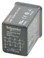
782XDXH10-24D
RELAY, 4PDT, 240VAC, 30VDC, 3A
⚠️ Reference pricing provided. In case of supply shortages, we will connect you with our trusted procurement partners to ensure your project's continuity.
- Manufacturer: SCHNEIDER ELECTRIC/LEGACY RELAY
- Product type: Power Relays
- Contact Configuration:4PDT; Coil Voltage:24VDC; Contact Current:3A; Product Range:782 Series; Relay Mounting:Socket; Coil Type:-; Contact Voltage VAC:240V; Relay Terminals:Quick Connect 10
- Coil Type: -
- Coil Voltage: 24VDC
- Product Range: 782 Series
- Relay Mounting: Socket
- Coil Resistance: 650ohm
- Contact Current: 3A
- Relay Terminals: Quick Connect
- Contact Material: Silver
- Contact Voltage VAC: 240V
- Contact Voltage VDC: 30V
- Contact Configuration: 4PDT
| Delivery and price | |
|---|---|
| Units per pack | 1 |
| Price | 121.67 € |
| Current stock | 200+ |
| Lead time | 30 days |
Datasheet

## Magnecraft[™] General Purpose Relays

Catalog 2012

_Contents_

## **Magnecraft[™] General Purpose Relays**

|Series Overview<br>�<br>|3|3|
|---|---|---|
|781 Series<br>�<br>||4|
|782 Power Series<br>�<br>8|||
|782 Control Series<br>�<br>||12|
|783 Series<br>�<br>||17|
|784 Series<br>�<br>||21|
|750 Series<br>�<br>||25|
|788 Series<br>�<br>||29|
|388J Series<br>�<br>33|||
|755 Latching Series<br>�<br>37|||
|785 Latching Series<br>�<br>41|||
|782H Hazardous Location Series<br>�<br>|45||
|750H Hazardous Location Series<br>�<br>|49||
|UL Listed Relay/Socket Combinations<br>�<br>||53|
|Sockets and Accessories<br>�<br>54|||
|Socket Specifcations<br>v<br>||54|
|Mounting Adapter Specifcations<br>v<br>||77|
|Socket Accessories<br>v<br>78|||
|Application Dat<br>�<br>a||85|
|Website Guid<br>�<br>e                                                                                                       87|||


2

## _Series Overview_

## **Magnecraft[™] General Purpose Relays**

Designed with specialized magnetic armatures and coils, Magnecraft General Purpose Relays easily handle current loads ranging from 10 mA to as large as 20 A . With multiple features, and a broad line of sockets and accessories, these relays offer the options needed to improve design, expedite installation and simplify testing of your application .

## **Key Features**

aa Socket, panel and DIN mounting options Ideal for MRO direct replacement a Multiple features and contact configurations available a UL Class I Division 2 models for hazardous a locations

Optional protection, mounting, and identification accessories

|**Series**<br>**781**<br>**782 Power**<br>**782 Control**<br>**783**<br>**784**<br>**750**<br>**788**<br>**388J**<br>**755**<br>**785**<br>**782H**<br>**750H**<br>E~~E~~<br>x ~~7 ~~<br>“S|<br>“<br>4—<br>r2|**Features**|**Terminals**|**Contact Configuration**|**Output Current**|**Page**|
|---|---|---|---|---|---|
||Plug-In Relay|Blade|SPDT|20 A|4|
|||||3 A||
||Plug-In Relay<br>~~|~~|Blade|SPDT|20 A|8|
||||DPDT|15 A||
||Plug-In Relay<br> ~~|~~|Blade|DPDT, 3PDT and 4PDT|10 A|12|
|||||3 A||
||Plug-In Relay|Blade|3PDT|15 A|17|
||Plug-In Relay|Blade|4PDT|15 A|21|
||Plug-In Relay|Octal (8 Pin)|SPDT and DPDT|16 A|25|
|||Octal (11 Pin)|3PDT|16 A||
||Plug-In Relay|Blade|SPDT, DPDT and 3PDT|16 A|29|
||Plug-In Relay|Blade|DPDT|20 A|33|
||Magnetic Latching Relay|Octal (8 Pin)|DPDT|16 A|37|
||Magnetic Latching Relay|Blade|DPDT|16 A|41|
||Hermetically Sealed<br>Relay|Blade|4PDT|5 A|45|
|||||3 A||
|||||1 A||
||Hermetically Sealed<br>Relay|Octal (8 Pin)|DPDT|12 A|49|
|||Octal (11 Pin)|3PDT|12 A||


3

## _Description_

## **Magnecraft[™] General Purpose Relays** 781 Series SPDT 20 A

## **Description**

The 781 Series plug-in relays offer clear or full-feature covers with multiple mounting options and accessories .

_UL listed when used with proper Magnecraft[™] sockets_

**Feature Benefit** 20 A max . switching current Ideal for automation control panels 14 mm width Slim design saves valuable space Clear or full-feature cover Full-feature covers include LED indicator & locking test button options Socket mount option Simplifies installation & maintenance while also allowing the use of protection modules, hold-down clips & other accessories Gold-flashed contacts Reduces contact oxidation & increases shelf life Mechanical flag indicator Standard feature displays relay status during testing or operation

**==> picture [172 x 7] intentionally omitted <==**

**----- Start of picture text -----**<br>
781 Clear Cover 781 Full-Feature Cover<br>**----- End of picture text -----**<br>


|**Contact Rating**|**Contact**<br>**Configuration**|**Nominal Voltage**|**Coil Resistance**<br>**(Ω)**|**Standard Part Number:**<br>**Clear Cover**|**Standard Part Number:**<br>**Full-Feature**|
|---|---|---|---|---|---|
|20 A|SPDT|24 Vac 50/60 Hz|180|781XAXC-24A|781XAXM4L-24A|
|||120 Vac 50/60 Hz|4430|781XAXC-120A|781XAXM4L-110/120A|
|||240 Vac 50/60 Hz|15720|–|781XAXM4L-240A|
|||12 Vdc|188|781XAXC-12D|781XAXM4L-12D|
|||24 Vdc|750|781XAXC-24D|781XAXM4L-24D|


**==> picture [511 x 114] intentionally omitted <==**

**----- Start of picture text -----**<br>
Part Number Explanation<br>Cn<br>Series:<br>781 = 781 Series<br>Coil Voltages:<br>            Relay<br>VAC = 6-240A<br>7 Cover Options: VDC = 6-125D<br>Contact Configuration: C = Clear Cover<br>XAX = SPDT M4L = Locking push<br> button & LED<br>**----- End of picture text -----**<br>


_*Please note that 3 A Bifurcated, PC Terminals, and LED-only versions are also available. Please contact Customer Service for more information (847-441-2540)._

4

**Magnecraft[™] General Purpose Relays** 781 Series SPDT 20 A

## _Specifications_

## **Specifications (UL 508)**

**==> picture [511 x 352] intentionally omitted <==**

**----- Start of picture text -----**<br>
Part Number 781XAX<br>Contact Characteristics<br>Terminal Style Blade<br>Contact Configuration SPDT<br>Maximum Current 20 A<br>Contact Materials Silver Alloy<br>Maximum Switching Voltage 300 V<br>Rated Switching Current at Voltage Resistive:  20 A at 277 Vac 50/60 Hz; 20 A at 28 Vdc<br>Motor:  1 hp at 250 Vac 50/60 Hz; 1/2 hp at 120 Vac 50/60 Hz<br>Pilot Duty:  B300<br>Minimum Switching Requirement 100 mA at 5 Vdc (0 .5 W)<br>Coil Characteristics<br>Maximum Operating Voltage 110% (AC / DC)<br>Maximum Pickup Voltage 85% (AC); 80% (DC)<br>Drop-out Voltage Threshold 15% (AC); 10% (DC)<br>Average Consumption 1 .0 VA (AC); 0 .8 W (DC)<br>General Characteristics<br>Electrical Life at Rated Load 100,000 operations<br>Mechanical Life (Unpowered) 10,000,000 operations<br>Operating Time (Response Time) 20 ms<br>Dielectric Strength - Between Coil and Contact (AC) 1500 V(rms)<br>Dielectric Strength - Between Poles (AC) 1500 V(rms)<br>Ambient Air Temperature around the Device - Storage -40 – +85 °C (-40 – +185 °F)<br>Ambient Air Temperature around the Device - Operation -40 – +55 °C (-40 – +131 °F)<br>Vibration Resistance - Operational 3 g-n at 10-55 Hz<br>Shock Resistance 10 g-n<br>Degree of Protection IP 40<br>Weight 29 g (1 .02 oz)<br>Agency Approvals UL with socket, UR (E43641), CE, CSA (LR40787), RoHS<br>**----- End of picture text -----**<br>


_Note: Actual product performance may vary depending on application and environmental conditions._

5

**Magnecraft[™] General Purpose Relays** 781 Series SPDT 20 A

_Dimensions, Wiring Diagram_

## **Dimensions — inches (millimeters)**

## **Clear Cover Dimensions**

**==> picture [153 x 93] intentionally omitted <==**

**----- Start of picture text -----**<br>
0.53<br>(14.0)<br>1.1<br>(27.9)<br>1.4<br>(35.5)<br>**----- End of picture text -----**<br>


## **Full-Feature Cover Dimensions**

**==> picture [176 x 94] intentionally omitted <==**

**----- Start of picture text -----**<br>
0.1 0.53<br>(2.1) (14.0)<br>1.1<br>(27.9)<br>1.6<br>(40.6)<br>**----- End of picture text -----**<br>


## **Wiring Diagram**

**==> picture [64 x 126] intentionally omitted <==**

**----- Start of picture text -----**<br>
SPDT<br>1<br>12<br>5<br>14<br>9<br>11<br>13 14<br>A1 A2<br>NEMA<br>IEC<br>**----- End of picture text -----**<br>


6

**Magnecraft[™] General Purpose Relays** 781 Series Accessories

## _Description_

## **Description**

Optional sockets offer customizable, finger-safe™ solutions including protection modules, hold-down clips, and ID tags . Sockets are DIN rail and panel mount compatible .

## **Relay Accessories**

|**Description**|**Function**|**For Use**<br>**With Relays**|**Pkg. Min.**|**Standard**<br>**Part Number**|
|---|---|---|---|---|
|Socket➊|DIN/Panel mount with screw terminals & clamping plates|781|10|70-781D5-1A|
|Socket<br>(2)|PCB-mount socket||10|70-781T-1|
|Adapter|Mount directly to DIN rail||10|16-781C|
|Adapter<br>~~e~~|Mount directly to panel||10|16-781C1|


## **Socket Accessories**

|**Description**|**Function**|**For Use With**<br>**Sockets**|**Coil**<br>**Voltage**|**Pkg.**<br>**Min.**|**Standard**<br>**Part Number**|
|---|---|---|---|---|---|
|Metal Spring Clip➊|Secures relay in socket|70-781D5-1A,, 70-781T-1|–|10|16-781SC|
|Plastic ID Hold-Down<br>Clip➋|Secures relay in socket<br>and provides labeling|70-781D5-1A|–|10|16-781IDC|
|Extruded Aluminum DIN<br>Rail, 39 .37'' (1000 mm) ➌|Quick installation and<br>removal of sockets|70-781D5-1A|–|10|16-700DIN|
|DIN Rail End Clip➌|Holds sockets firmly in<br>place on DIN rail|–|–|10|16-DCLIP-1|
|Small Socket Module|Protection Diode<br>_(Protects external drive_<br>_circuitry from inductive_<br>_voltages)_|70-781D5-1A|6 to 250 Vdc|10|70-BSMD-250|
|Small Socket Module➍|LED Indicator_(Provides_<br>_coil status at a glance)_||24 Vac/Vdc|10|70-BSMLG-24|
|Small Socket Module|MOV Suppressor<br>_(Protects from damaging_<br>_electrical spikes)_||120 Vac/Vdc|10|70-BSMM-120|
||||24 Vac/Vdc|10|70-BSMM-24|
||||240 Vac/Vdc|10|70-BSMM-240|


_Note: Use of LED socket module may increase coil power draw by up to 10%._

7

## _Description_

## **Magnecraft[™] General Purpose Relays** 782 Power Series SPDT 20 A; DPDT 15 A

## **Description**

The 782 Plug-in Power relays offer clear or full-feature covers with multiple mounting options and accessories .

_UL listed when used with proper Magnecraft[™] sockets_

|The 782 Plug-in Power relays offer clear or full-feature covers with multiple mounting<br>options and accessories .|The 782 Plug-in Power relays offer clear or full-feature covers with multiple mounting|
|---|---|
|**Feature**<br>20 A / 15 A max . switching<br>current|**Benefit**<br>Ideal for automation control panels|
|Clear or full-feature cover<br>options|Full-feature covers include LED indicator & locking test button|
|Socket mount option|Simplifies installation & maintenance while also allowing the use<br>of protection modules, hold-down clips & other accessories|
|Gold-flashed contacts|Reduces contact oxidation & increases shelf life|
|Mechanical flag indicator|Standard feature displays relay status during testing or<br>operation|


_782 Clear Cover 782 Full-Feature Cover_

|**Contact**<br>**Rating**|**Contact**<br>**Configuration**|**Nominal Voltage**|**Coil**<br>**Resistance (Ω)**|**Feature**|**Standard Part Number:**<br>**Clear Cover**|**Standard Part Number:**<br>**Full-Feature**|
|---|---|---|---|---|---|---|
|15 A|DPDT|24 Vac 50/60 Hz<br>~~a~~<br>~~a~~|180<br>~~a~~<br>~~ee~~|–<br>~~**ee**~~|782XBXC-24D<br>~~**ee**~~|782XBXM4L-24A|
|||||LED<br>~~**ee**~~<br>~~**e**~~|782XBXCL-24A<br>~~**ee**~~<br>~~**e**e~~|–|
|||120 Vac 50/60 Hz<br>~~a~~<br>~~a~~<br>~~a~~|4430<br>~~a ~~<br>~~ee~~<br>~~es~~|–<br> ~~**ee**~~<br>~~**e**~~|782XBXC-120A<br>~~**ee**~~<br>~~**e**e~~|782XBXM4L-120A|
|||||PC Terminals<br>~~**e**~~<br>~~es~~|782XBXCT-120A<br>~~**e**e~~<br>~~s~~|–|
|||220/240 Vac 50/60 Hz<br>~~a~~<br>~~e~~<br>~~a~~|15720<br>~~ee~~<br>~~es~~<br>~~es~~<br>~~ee~~|–<br>~~**e**~~<br>~~s~~<br>~~es~~<br>~~ee~~|782XBXC-24A<br>~~**e**e~~<br>~~s~~<br>~~ee~~|782XBXM4L-240A|
|||12 Vdc<br>~~e~~<br>~~a~~<br>~~ee~~|160<br>~~es~~<br>~~es ~~<br>~~ee~~|–<br>~~s~~<br>~~es~~<br>~~ee~~|782XBXC-12D<br>~~s~~<br>~~ee~~|782XBXM4L-12D|
|||||PC Terminals<br> ~~es~~<br>~~ee~~<br>~~**es**~~<br>~~ee~~|782XBXCT-12D<br>~~ee~~<br>~~**es**~~<br>~~ee~~|–|
|||24 Vdc<br>~~ee~~<br>~~a~~|650<br>~~ee~~<br>~~ee~~|–<br>~~ee~~<br>~~**es**~~<br>~~ee~~|–<br>~~ee~~<br>~~**es**~~<br>~~ee~~|782XBXM4L-24D|
|||||PC Terminals<br>~~**es**~~<br>~~ee~~<br>~~eee~~|782XBXCT-24D<br>~~**es**~~<br>~~ee~~<br>~~ee~~|–|
|||110/125 Vdc<br>~~ee~~<br>~~a~~<br>~~ee~~|11000<br>~~ee~~|–<br>~~**es**~~<br>~~ee~~<br>~~eee~~|782XBXC-110D<br>~~**es**~~<br>~~ee~~<br>~~ee~~|782XBXM4L-110D|
|||||LED<br>~~eee~~<br>~~ee~~<br>~~rT~~|782XBXCL-110D<br>~~ee~~<br>~~ee~~<br>~~rT~~|–|
|20 A|SPDT|24 Vac 50/60 Hz<br>~~a~~<br>~~ee~~<br>~~t~<C~sSC“‘CSNC*”S~~|180<br>~~ee ~~<br>~~t~<C~sSC“‘CSNC*”S~~|–<br> ~~eee~~<br>~~ee~~<br>~~rT~~<br>~~ee~~<br>~~ee~~|–<br>~~ee~~<br>~~ee~~<br>~~rTt~‘“:;S~SCSY~~|782XAXM4L-24A|
|||120 Vac 50/60 Hz<br>~~ee~~<br>~~t~<C~sSC“‘CSNC*”S~~<br>~~ee~~<br>~~es~~|4430<br>~~t~<C~sSC“‘CSNC*”S~~<br>~~ee~~||–<br>~~ee~~<br>~~rTt~‘“:;S~SCSY~~<br>~~t~—“—s~SSY~~<br>~~Pe~~|782XAXM4L-120A|
|||220/240 Vac 50/60 Hz<br>~~t~<C~sSC“‘CSNC*”S~~<br>~~ee~~<br>~~es~~|15720<br>~~t~<C~sSC“‘CSNC*”S~~<br>~~ee~~||782XAXC-240A<br>~~t~‘“:;S~SCSY~~<br>~~t~—“—s~SSY~~<br>~~Pe~~|782XAXM4L-240A|
|||12 Vdc<br>~~ee~~<br>~~es~~<br>~~t~<C~sSC“‘CSNC*”S~~|160<br>~~ee~~<br>~~t~<C~sSC“‘CSNC*”S~~||–<br>~~t~—“—s~SSY~~<br>~~Pe~~<br>~~rt~‘“CS~S~SCSY~~|782XAXM4L-12D|
|||24 Vdc<br>~~es~~<br>~~t~<C~sSC“‘CSNC*”S~~<br>~~ee~~|650<br>~~ee~~<br>~~t~<C~sSC“‘CSNC*”S~~<br>~~ee~~||–<br>~~Pe~~<br>~~rt~‘“CS~S~SCSY~~<br>~~t~—“—s~SSY~~<br>~~Po~~|782XAXM4L-24D|
|||110/125 Vdc<br>~~t~<C~sSC“‘CSNC*”S~~<br>~~ee~~|11000<br>~~t~<C~sSC“‘CSNC*”S~~<br>~~ee~~||782XAXC-110D<br>~~rt~‘“CS~S~SCSY~~<br>~~t~—“—s~SSY~~<br>~~Po~~|782XAXM4L-110D|


## **Part Number Explanation** hii ~~eee~~

Series: 782 = 782 Series Power Relay

Contact Configuration: XAX = SPDT XBX = DPDT

Coil Voltages: VAC = 6-240A Cover Options: VDC = 6-125D C = Clear Cover CL = LED CT = PC Termimals M4L = Locking push button & LED

_*Please note that LED-only versions are also available. Please contact Customer Service for more information (847-441-2540)._

8

_Specifications_

**Magnecraft[™] General Purpose Relays** 782 Power Series SPDT 20 A; DPDT 15 A

## **Specifications (UL 508)**

**==> picture [512 x 400] intentionally omitted <==**

**----- Start of picture text -----**<br>
Part Number 782XAX 782XBXC / CL / M4L  782XBXCT<br>Contact Characteristics<br>Terminal Style Blade Blade PC Terminals<br>Contact Configuration SPDT DPDT<br>Maximum Current 20 A 15 A<br>Contact Materials Silver Alloy Silver Alloy<br>Maximum Switching Voltage 300 V 300 V<br>Rated Switching Current at Voltage Resistive:  20 A at 120 Vac 50/60 Hz; 20 A at 277  Resistive:  10 A at 277 Vac 50/60 Hz (CSA); 12 A<br>Vac 50/60 Hz; 20 A at 28 Vdc at 277 Vac 50/60 Hz; 15 A at 120 Vac 50/60 Hz; 12<br>Motor:  1 hp at 250 Vac 50/60 Hz; 1/2 hp at 120 Vac  A at 28 Vdc<br>50/60 Hz Motor:  1 hp at 250 Vac 50/60 Hz; 1/2 hp at 120<br>Pilot Duty:  B300 Vac 50/60 Hz<br>Pilot Duty:  B300<br>Minimum Switching Requirement 100 mA at 5 Vdc (0 .5 W) 100 mA at 5 Vdc (0 .5 W)<br>Coil Characteristics<br>Maximum Operating Voltage 110% (AC / DC) 110% (AC / DC)<br>Maximum Pickup Voltage 85% (AC); 80% (DC) 85% (AC); 80% (DC)<br>Drop-out Voltage Threshold 15% (AC); 10% (DC) 15% (AC); 10% (DC)<br>Average Consumption 1 .2 VA (AC); 0 .9 W (DC) 1 .2 VA (AC); 0 .9 W (DC)<br>General Characteristics<br>Electrical Life at Rated Load 100,000 operations 100,000 operations<br>Mechanical Life (Unpowered) 10,000,000 operations 10,000,000 operations<br>Operating Time (Response Time) 20 ms 20 ms<br>Dielectric Strength - Between Coil and Contact (AC) 1600 V(rms) 1600 V(rms)<br>Dielectric Strength - Between Poles (AC) 1600 V(rms) 1600 V(rms)<br>Ambient Air Temperature around the Device -  -40 – +85 °C (-40 – +185 °F) -40 – +85 °C (-40 – +185 °F)<br>Storage<br>Ambient Air Temperature around the Device -  -40 – +55 °C (-40 – +131 °F) -40 – +55 °C (-40 – +131 °F)<br>Operation<br>Vibration Resistance - Operational 3 g-n at 10-55 Hz 3 g-n at 10-55 Hz<br>Shock Resistance 10 g-n 10 g-n<br>Degree of Protection IP 40 IP 40<br>Weight 36 g (1 .27 oz) 36 g (1 .27 oz)<br>Agency Approvals UL with socket, UR (E43641), CE, CSA (LR40787),  UL with socket, UR (E43641), CE, CSA (LR40787),<br>RoHS RoHS<br>**----- End of picture text -----**<br>


_Note: Actual product performance may vary depending on application and environmental conditions._

9

**Magnecraft[™] General Purpose Relays** 782 Power Series SPDT 20 A; DPDT 15 A

_Dimensions, Wiring Diagrams_

## **Dimensions — inches (millimeters)**

## **Clear Cover Dimensions**

**==> picture [84 x 79] intentionally omitted <==**

**----- Start of picture text -----**<br>
Printed Circuit Terminals<br>0.02<br>(0.5) 0.14<br>(3.56)<br>0.04<br>(1.02)<br>0.1<br>(2.54)<br>**----- End of picture text -----**<br>


**==> picture [172 x 87] intentionally omitted <==**

**----- Start of picture text -----**<br>
0.29 0.83<br>(7.4) 0.02 (21.0)<br>(0.5)<br>1.1<br>(27.9)<br>1.4 0.187<br>(35.5) (4.8)<br>**----- End of picture text -----**<br>


**==> picture [357 x 124] intentionally omitted <==**

**----- Start of picture text -----**<br>
Terminal Layout<br>Full-Feature Cover Dimensions 0.38 0.16<br>(9.9) (4.7) 0.23<br>0.27 0.29 0.83 (5.9)<br>(7.0) (7.4) (21.0) 0.30<br>0.02 (7.5)<br>(0.5)<br>1.1<br>(27.9) 0.08<br>(2.1) 2X<br>0.55<br>1.54 0.187 (14.1)<br>(39.1) (4.8)<br>**----- End of picture text -----**<br>


## **Full-Feature Cover Dimensions**

## **Wiring Diagrams**

**==> picture [159 x 115] intentionally omitted <==**

**----- Start of picture text -----**<br>
SPDT DPDT<br>1 4 1 4<br>12 42 12 42<br>5 8 5 8<br>14 44 14 44<br>9 12 9 12<br>11 41 11 41<br>13 14 13 14<br>A1 A2 A1 A2<br>NEMA NEMA<br>IEC IEC<br>**----- End of picture text -----**<br>


10

**Magnecraft[™] General Purpose Relays** 782 Power Series Accessories

_Description_

## **Description**

Optional sockets offer customizable, finger-safe™ solutions including protection modules, hold-down clips, and ID tags . Sockets are DIN rail and panel mount compatible .

## **Relay Accessories**

||**Relay Accessories**||
|---|---|---|
||**Description**<br>**Function**<br>**For Use With**<br>**Relays**<br>**Pkg. Min.**<br>Socket➊<br>DIN/Panel mount with screw terminals & clamping<br>plates<br>10|**Standard**<br>**Part Number**<br>70-782D8-1A|
||782XAX / 782XBX<br>Socket➋<br>DIN/Panel mount with screw terminals & clamping<br>plates<br>10<br>Socket➌<br>Quick Connect terminals for chassis mount<br>10|70-459-1<br>70-401-1|
||Socket➍<br>Printed circuit terminals for PCB mount<br>10|70-402-1|
||Adapter➎<br>Mount directly to panel<br>10|16-782C1|
||Adapter➏<br>Mount directly to DIN rail<br>10|16-782C|
|**Socket Accessories**|**Socket Accessories**||
||**Description**<br>**Function**<br>**For Use With**<br>**Sockets**<br>**Coil**<br>**Voltage**<br>**Pkg.**<br>**Min.**|**Standard**<br>**Part Number**|
||Metal Spring Clip➊ ➋<br>Secures relay in socket<br>70-782D8-1A, 70-459-1,<br>70-401-1, 70-402-1<br>–<br>10|16-1342|
||Plastic Hold-Down Clip➌<br>Secures relay in socket<br>or ejects relay off socket<br>70-782D8-1A<br>–<br>10<br>Write-on tag➍<br>Write-on tag for<br>16-782PC-1 hold-down<br>Clip<br>–<br>–<br>10<br>Plastic ID Hold-Down<br>Clip➎<br>Secures relay in socket<br>and provides labeling<br>70-782D8-1A, 70-459-1,<br>70-401-1, 70-402-1<br>–<br>10<br>Extruded Aluminum DIN<br>Rail, 39 .37'' (1000 mm)➏<br>Quick installation and<br>removal of sockets<br>70-782D8-1A, 70-459-1<br>–<br>10<br>DIN Rail End Clip➏<br>Holds sockets firmly in<br>place on DIN rail<br>70-782D8-1A, 70-459-1<br>–<br>10<br>Small Socket Module<br>Protection Diode<br>_(Protects external drive_<br>_circuitry from inductive_<br>_voltages)_<br>70-782D8-1A<br>6 to 250 Vdc<br>10<br>Small Socket Module➐<br>LED Indicator_(Provides_<br>_coil status at a glance)_<br>24 Vac/Vdc<br>10<br>Small Socket Module<br>MOV Suppressor<br>_(Protects from damaging_<br>_electrical spikes)_<br>120 Vac/Vdc<br>10<br>24 Vac/Vdc<br>10<br>240 Vac/Vdc<br>10<br>~~ee ee eee~~<br>~~|~~<br>~~ee~~<br>~~ee~~<br>~~ee~~<br>~~ee~~<br>~~ee~~<br>~~ee~~<br>~~ee ee~~<br>~~PF~~<br>~~= =~~<br>~~ie~~<br>~~—~~|16-782PC-1<br>16-700ST-1<br>16-782IDC<br>16-700DIN<br>16-DCLIP-1<br>70-BSMD-250<br>70-BSMLG-24<br>70-BSMM-120<br>70-BSMM-24<br>70-BSMM-240|
|_Note: Use of LED socket module may increase coil power draw by up to 10%._|||


## **Socket Accessories**

11

## _Description_

## **Magnecraft[™] General Purpose Relays** 782 Control Series DPDT 3 A and 10 A; 4PDT 3 A and 10 A

## **Description**

_UL listed when used with proper Magnecraft[™] sockets_

The 782 Plug-in Control relays offer clear or full-feature covers with multiple mounting options and accessories; 4PDT models save valuable space while adding increased functionality .

|options and accessories; 4PDT models save valuable space while adding increased<br>functionality .|options and accessories; 4PDT models save valuable space while adding increased|
|---|---|
|**Feature**<br>10 A / 3 A max . switching<br>current|**Benefit**<br>Ideal for automation panels & controls|
|Clear or full-feature cover<br>options|Full-feature covers include LED indicator & locking test button|
|DPDT & 4PDT contact|Simultaneously control separate circuit configurations|
|Socket mount option<br>~~i~~|Simplifies installation and maintenance while also allowing<br>the use of protection modules, hold-down clips & other<br>accessories|
|Gold-flashed contacts|Reduces contact oxidation & increases shelf life|
|Mechanical flag indicator|Standard feature displays relay status during testing or<br>operation|


**==> picture [209 x 49] intentionally omitted <==**

**----- Start of picture text -----**<br>
]X<br>i<br>S<br>‘<br>782 Clear Cover 782 Full-Feature Cover<br>**----- End of picture text -----**<br>


|**Contact**<br>**Rating**<br>**Contact**<br>**Configuration**<br>**Nominal**<br>**Voltage**<br>**Coil Resistance**<br>**(Ω)**<br>**Feature**<br>**Standard Part**<br>**Number: Clear Cover**<br>**Standard Part**<br>**Number: Full-Feature**<br>3 A<br>4PDT<br>12 Vac 50/60 Hz<br>46<br>Bifurcated Contacts<br>782XDX3C-12A<br>–<br>24 Vac 50/60 Hz<br>180<br>Bifurcated Contacts<br>782XDX3C-24A<br>782XDX3M4L-24A<br>Gold Diffused Contacts<br>782XDX1C-24A<br>–<br>120 Vac 50/60 Hz<br>4430<br>Bifurcated Contacts<br>782XDX3C-120A<br>782XDX3M4L-120A<br>Gold Diffused Contacts<br>782XDX1C-120A<br>782XDX1M4L-120A<br>12 Vdc<br>160<br>Bifurcated Contacts<br>782XDX3C-12D<br>782XDX3M4L-12D<br>Gold Diffused Contacts<br>782XDX1C-12D<br>782XDX1M4L-12D<br>24 Vdc<br>650<br>Bifurcated Contacts<br>782XDX3C-24D<br>782XDX3M4L-24D<br>Gold Diffused Contacts<br>782XDX1C-24D<br>782XDX1M4L-24D<br>110/125 Vdc<br>11000<br>Bifurcated Contacts<br>782XDX3C-110D<br>–<br>10 A<br>DPDT<br>24 Vac 50/60 Hz<br>180<br>–<br>–<br>782XBX2M4L-24A<br>120 Vac 50/60 Hz<br>4430<br>–<br>782XBX2M4L-120A<br>12 Vdc<br>160<br>–<br>782XBX2M4L-12D<br>24 Vdc<br>650<br>–<br>782XBX2M4L-24D<br>110/125 Vdc<br>11000<br>–<br>782XBX2M4L-110D<br>4PDT<br>24 Vac 50/60 Hz<br>180<br>–<br>782XDX2M4L-24A<br>120 Vac 50/60 Hz<br>4430<br>782XDX2C-120A<br>782XDX2M4L-120A<br>12 Vdc<br>160<br>–<br>782XDX2M4L-12D<br>24 Vdc<br>650<br>782XDX2C-24D<br>782XDX2M4L-24D<br>110/125 Vdc<br>11000<br>–<br>782XDX2M4L-110D<br>~~a es~~<br>~~ee~~<br>~~es~~<br>~~ee~~<br>~~a~~<br>~~ee ees eee~~<br>~~ee~~<br>~~es eee~~<br>~~ee~~<br>~~es~~<br>~~eee~~<br>~~es~~<br>~~a~~<br>~~PF~~<br>~~S==~~<br>~~**Po**~~<br>~~a~~<br>~~ee~~<br>~~Po~~<br>~~a~~<br>~~Po~~<br>~~a~~<br>~~a~~<br>~~Po~~<br>~~a~~<br>~~ee~~<br>~~Po~~<br>~~a~~<br>~~Po~~<br>~~= =~~<br>~~a~~<br>~~Po~~|
|---|
|**Part Number Explanation**<br>~~_L~~|
|Series:<br>782 =782 Series<br>Control Relay<br>Contact Configuration:<br>XBX =DPDT<br>XDX =4PDT<br>Cover Options:<br>C =Clear Cover<br>M4L =Locking push<br>button & LED<br>Coil Voltages:<br>VAC =6-240A<br>VDC =6-125D<br>Contact Code:<br>1 =3 A Fine Silver, Gold Diffused<br>_*Please note that LED-only versions are_<br>_also available. Please contact Customer_<br>|<br>:|
|2 =10 A Silver Alloy<br>3 =3 A Bifurcated<br>_Service for more information (847-441-2540)._|


12

_Specifications_

## **Magnecraft[™] General Purpose Relays** 782 Control Series DPDT 3 A and 10 A; 4PDT 3 A and 10 A

## **Specifications (UL 508)**

**==> picture [512 x 419] intentionally omitted <==**

**----- Start of picture text -----**<br>
Part Number 782XBX1 782XBX2 782XBX3<br>Contact Characteristics<br>Terminal Style Blade Blade Blade<br>Contact Configuration DPDT DPDT DPDT<br>Maximum Current 3 A 10 A 3 A<br>Load Type Low Level Standard Low Level<br>Contact Materials Fine Silver Silver Alloy Bifurcated<br>Maximum Switching Voltage 300 V 300 V 300 V<br>Rated Switching Current at Voltage Resistive:  3 A at 120 Vac 50/60 Hz; 3  Resistive:  10 A at 120 Vac 50/60 Hz;  Resistive:  3 A at 120 Vac 50/60 Hz; 3<br>A at 277 Vac 50/60 Hz; 3 A at 30 Vdc 8 A at 277 Vac 50/60 Hz; 8 A at 28 Vdc A at 277 Vac 50/60 Hz; 3 A at 30 Vdc<br>Motor:  1/16 hp at 120 Vac 50/60 Hz Motor:  1 hp at 277 Vac 50/60 Hz; 1/3  Motor:  1/16 hp at 120 Vac 50/60 Hz<br>Pilot Duty:  B300 hp at 120 Vac 50/60 Hz Pilot Duty:  B300<br>Pilot Duty:  B300<br>Minimum Switching Requirement 10 mA at 5 Vdc (0 .5 W) 100 mA at 5 Vdc (0 .5 W) 10 mA at 5 Vdc (0 .5 W)<br>Coil Characteristics<br>Maximum Operating Voltage 110% (AC / DC) 110% (AC / DC) 110% (AC / DC)<br>Maximum Pickup Voltage 85% (AC); 80% (DC) 85% (AC); 80% (DC) 85% (AC); 80% (DC)<br>Drop-out Voltage Threshold 15% (AC); 10% (DC) 15% (AC); 10% (DC) 15% (AC); 10% (DC)<br>Average Consumption 1 .2 VA (AC); 0 .9 W (DC) 1 .2 VA (AC); 0 .9 W (DC) 1 .2 VA (AC); 0 .9 W (DC)<br>General Characteristics<br>Electrical Life at Rated Load 100,000 operations 200,000 operations 100,000 operations<br>Mechanical Life (Unpowered) 10,000,000 operations 10,000,000 operations 10,000,000 operations<br>Operating Time (Response Time) 20 ms 20 ms 20 ms<br>Dielectric Strength - Between Coil and  1600 V(rms) 1600 V(rms) 1600 V(rms)<br>Contact (AC)<br>Dielectric Strength - Between Poles (AC) 1600 V(rms) 1600 V(rms) 1600 V(rms)<br>Ambient Air Temperature around the  -40 – +85 °C (-40 – +185 °F) -40 – +85 °C (-40 – +185 °F) -40 – +85 °C (-40 – +185 °F)<br>Device - Storage<br>Ambient Air Temperature around the  -40 – +55 °C (-40 – +131 °F) -40 – +55 °C (-40 – +131 °F) -40 – +55 °C (-40 – +131 °F)<br>Device - Operation<br>Vibration Resistance - Operational 3 g-n at 10-55 Hz 3 g-n at 10-55 Hz 3 g-n at 10-55 Hz<br>Shock Resistance 10 g-n 10 g-n 10 g-n<br>Degree of Protection IP 40 IP 40 IP 40<br>Weight 36 g (1 .27 oz) 36 g (1 .27 oz) 36 g (1 .27 oz)<br>Agency Approvals UL with socket, UR (E43641), CE,  UL with socket, UR (E43641), CE,  UL with socket, UR (E43641), CE,<br>CSA (LR40787), RoHS CSA (LR40787), RoHS CSA (LR40787), RoHS<br>**----- End of picture text -----**<br>


_Note: Actual product performance may vary depending on application and environmental conditions._

13

## _Specifications (continued)_

## **Magnecraft[™] General Purpose Relays** 782 Control Series DPDT 3 A and 10 A; 4PDT 3 A and 10 A

## **Specifications (UL 508)** _**(continued)**_

**==> picture [512 x 419] intentionally omitted <==**

**----- Start of picture text -----**<br>
Part Number 782XDX1 782XDX2 782XDX3<br>Contact Characteristics<br>Terminal Style Blade Blade Blade<br>Contact Configuration 4PDT 4PDT 4PDT<br>Maximum Current 3 A 10 A 3 A<br>Load Type Standard Standard Low Level<br>Contact Materials Fine Silver Silver Alloy Bifurcated<br>Maximum Switching Voltage 300 V 300 V 300 V<br>Rated Switching Current at Voltage Resistive:  10 A at 120 Vac 50/60 Hz;  Resistive:  10 A at 120 Vac 50/60 Hz;  Resistive:  3 A at 120 Vac 50/60 Hz; 3<br>8 A at 277 Vac 50/60 Hz; 8 A at 28 Vdc 8 A at 277 Vac 50/60 Hz; 8 A at 28 Vdc A at 277 Vac 50/60 Hz; 3 A at 30 Vdc<br>Motor:  1 hp at 277 Vac 50/60 Hz; 1/3  Motor:  1 hp at 277 Vac 50/60 Hz; 1/3  Motor:  1/16 hp at 120 Vac 50/60 Hz<br>hp at 120 Vac 50/60 Hz hp at 120 Vac 50/60 Hz Pilot Duty:  B300<br>Pilot Duty:  B300 Pilot Duty:  B300<br>Minimum Switching Requirement 100 mA at 5 Vdc (0 .5 W) 100 mA at 5 Vdc (0 .5 W) 10 mA at 5 Vdc (0 .5 W)<br>Coil Characteristics<br>Maximum Operating Voltage 110% (AC / DC) 110% (AC / DC) 110% (AC / DC)<br>Maximum Pickup Voltage 85% (AC); 80% (DC) 85% (AC); 80% (DC) 85% (AC); 80% (DC)<br>Drop-out Voltage Threshold 15% (AC); 10% (DC) 15% (AC); 10% (DC) 15% (AC); 10% (DC)<br>Average Consumption 1 .2 VA (AC); 0 .9 W (DC) 1 .2 VA (AC); 0 .9 W (DC) 1 .2 VA (AC); 0 .9 W (DC)<br>General Characteristics<br>Electrical Life at Rated Load 200,000 operations 200,000 operations 200,000 operations<br>Mechanical Life (Unpowered) 10,000,000 operations 10,000,000 operations 10,000,000 operations<br>Operating Time (Response Time) 20 ms 20 ms 20 ms<br>Dielectric Strength - Between Coil and  1600 V(rms) 1600 V(rms) 1600 V(rms)<br>Contact (AC)<br>Dielectric Strength - Between Poles (AC) 1600 V(rms) 1600 V(rms) 1600 V(rms)<br>Ambient Air Temperature around the  -40 – +85 °C (-40 – +185 °F) -40 – +85 °C (-40 – +185 °F) -40 – +85 °C (-40 – +185 °F)<br>Device - Storage<br>Ambient Air Temperature around the  -40 – +55 °C (-40 – +131 °F) -40 – +55 °C (-40 – +131 °F) -40 – +55 °C (-40 – +131 °F)<br>Device - Operation<br>Vibration Resistance - Operational 3 g-n at 10-55 Hz 3 g-n at 10-55 Hz 3 g-n at 10-55 Hz<br>Shock Resistance 10 g-n 10 g-n 10 g-n<br>Degree of Protection IP 40 IP 40 IP 40<br>Weight 36 g (1 .27 oz) 36 g (1 .27 oz) 36 g (1 .27 oz)<br>Agency Approvals UL with socket, UR (E43641), CE,  UL with socket, UR (E43641), CE,  UL with socket, UR (E43641), CE,<br>CSA (LR40787), RoHS CSA (LR40787), RoHS CSA (LR40787), RoHS<br>**----- End of picture text -----**<br>


_Note: Actual product performance may vary depending on application and environmental conditions._

14

**Magnecraft[™] General Purpose Relays** 782 Control Series DPDT 3 A and 10 A; 4PDT 3 A and 10 A

_Dimensions, Wiring Diagrams_

## **Dimensions — inches (millimeters)**

## **Clear Cover Dimension**

**==> picture [152 x 87] intentionally omitted <==**

**----- Start of picture text -----**<br>
0.83<br>(21.0)<br>1.1<br>(27.9)<br>1.4 0.24<br>(35.5) (6.0)<br>**----- End of picture text -----**<br>


## **Full-Feature Cover Dimension**

**==> picture [186 x 88] intentionally omitted <==**

**----- Start of picture text -----**<br>
0.27 0.83<br>0.02<br>(7.0) (21.0)<br>(0.5)<br>1.1<br>(27.9)<br>1.54 0.24<br>(39.1) (6.0)<br>**----- End of picture text -----**<br>


## **Wiring Diagrams**

## **DPDT 4PDT**

**==> picture [185 x 110] intentionally omitted <==**

**----- Start of picture text -----**<br>
1 4 1 2 3 4<br>12 42 12 22 32 42<br>5 8 5 6 7 8<br>14 44 14 24 34 44<br>9 12 9 10 11 12<br>11 41 11 21 31 41<br>13 14 13 14<br>A1 A2 A1 A2<br>NEMA NEMA<br>IEC IEC<br>**----- End of picture text -----**<br>


15

**Magnecraft[™] General Purpose Relays** 782 Control Series Accessories

## _Description_

## **Description**

Optional sockets offer customizable, finger-safe™ solutions including protection modules, hold-down clips, and ID tags . Sockets are DIN rail and panel mount compatible .

## **Relay Accessories**

|**Description**|**Function**|**For Use**<br>**With Relays**|**Pkg.**<br>**Min.**|**Standard**<br>**Part Number**|
|---|---|---|---|---|
|Socket➊|DIN/Panel mount with elevator terminals|782XBX1,2,3|10|70-782EL8-1|
|Socket➋|DIN/Panel mount with screw terminals & clamping plates|782XBX1,2,3 /<br>782XDX1,2,3|10|70-782D14-1|
|Socket➌|DIN/Panel mount with rising elevator box terminals|782XBX1,2,3 /<br>782XDX1,2,3|10|70-782E14-1|
|Socket➍|DIN/Panel mount with elevator terminals|782XBX1,2,3 /<br>782XDX1,2,3|10|70-782EL14-1|
|Socket➎|DIN/Panel mount with screw terminals & clamping plates|782XDX1,2,3|10|70-461-1|
|Socket➏|Solder terminals for chassis mount|782XDX1,2,3|10|70-378-1|
|Socket➐|Printed circuit terminals for PCB mount|782XDX1,2,3|10|70-379-1|
|Adapter➑|Mount directly to DIN rail|782XBX1,2,3 /<br>782XDX1,2,3|10|16-782C|
|Adapter➒|Mount directly to panel|782XBX1,2,3 /<br>782XDX1,2,3|10|16-782C1|


## **Socket Accessories**

|**Description**|**Function**|**For Use With**<br>**Sockets**|**Coil**<br>**Voltage**|**Pkg.**<br>**Min.**|**Standard**<br>**Part**<br>**Number**|
|---|---|---|---|---|---|
|Metal Spring Clip➊<br>~~—~~|Secures relay in socket<br>~~—~~|70-782D14-1,<br>70-782E14-1,<br>70-782EL14-1,<br>70-782EL8-1|–<br>~~—_~~|10|16-782SC|
|Plastic Hold-Down Clip➋<br>~~—~~|Secures relay in socket or<br>ejects relay off socket<br>~~—~~||–<br>~~—_~~|10|16-782PC-1|
|Write-on tag➌<br>~~—~~|Small Write-on tag<br>~~—~~||–<br>~~—_~~|10|16-782FT-1|
|Write-on tag➍|Write-on tag for 16-782PC-1<br>Hold-down Clip|–|–|10|16-700ST-1|
|Extruded Aluminum DIN<br>Rail, 39 .37'' (1000 mm)➎<br>~~_~~|Quick installation and<br>removal of sockets<br>~~_~~<br>~~a~~|70-782D14-1, 70-782E14-1,<br>70-782EL8-1, 70-782EL14-1<br>~~_~~<br>~~a~~|–<br>~~_~~<br>~~a~~|10<br>~~_~~<br>~~a~~|16-700DIN<br>~~_~~<br>~~a~~|
|DIN Rail End Clip➎<br>~~_~~<br>~~g~~|Holds sockets firmly in<br>place on DIN rail<br>~~_~~<br>~~g~~<br>~~a~~|–<br>~~_~~<br>~~g~~<br>~~a~~|–<br>~~_~~<br>~~g~~<br>~~a~~|10<br>~~_~~<br>~~g~~<br>~~a~~|16-DCLIP-1<br>~~_~~|
|Insulated Coil Bus Jumper<br>System➏<br>~~g~~|Wireless socket connec-<br>tion<br>~~g~~<br>~~a~~|70-782EL8-1, 70-782EL14-1<br>~~g~~<br>~~a~~|–<br>~~g~~<br>~~a~~|10<br>~~g~~<br>~~a~~|16-782CBJ-1|
|Small Socket Module|Protection Diode_(Protects_<br>_external drive circuitry_<br>_from inductive voltages)_<br>~~a~~<br>~~—~~|70-782D14-1,<br>70-782E14-1,<br>70-782EL14-1,<br>70-782EL8-1<br>~~a~~|6 to 250 Vdc<br>~~a~~|10<br>~~a~~|70-BSMD-250|
|Small Socket Module➐|LED Indicator_(Provides_<br>_coil status at a glance)_<br>~~—~~||24 Vac/Vdc|10|70-BSMLG-24|
|Small Socket Module|MOV Suppressor<br>_(Protects from damaging_<br>_electrical spikes)_<br>~~—~~||120 Vac/Vdc<br>~~—_~~|10<br>~~—_~~|70-BSMM-120|
||||24 Vac/Vdc<br>~~—_~~<br>~~P|~~|10<br>~~—_~~<br>~~P|~~|70-BSMM-24|
||||240 Vac/Vdc<br>~~PT~~|10<br>~~PT~~|70-BSMM-240|


_Note: Use of LED socket module may increase coil power draw by up to 10%._

16

## _Description_

## **Magnecraft[™] General Purpose Relays** 783 Series 3PDT 15 A

## **Description**

The 783 Series plug-in relays offer clear or full-feature covers with multiple mounting options and accessories .

_UL listed when used with proper Magnecraft[™] sockets_

|**Feature**<br>15 A max . switching current|**Benefit**<br>Ideal for automation panels & controls|
|---|---|
|Clear or full-feature cover<br>options|Full-feature covers include LED indicator & locking test button|
|3PDT contact configuration|Simultaneously control up to 3 separate circuits|
|Socket mount option|Simplifies installation & maintenance while also allowing the use<br>of protection modules, hold-down clips & other accessories|
|Gold-flashed contacts|Reduces contact oxidation & increases shelf life|
|Mechanical flag indicator|Standard feature displays relay status during testing or<br>operation|


**==> picture [177 x 7] intentionally omitted <==**

**----- Start of picture text -----**<br>
783 Clear Cover 783 Full-Feature Cover<br>**----- End of picture text -----**<br>


|**Contact Rating**|**Contact**<br>**Configuration**|**Nominal Voltage**|**Coil**<br>**Resistance (Ω)**|**Standard Part Number:**<br>**Clear Cover**|**Standard Part Number:**<br>**Full-Feature**|
|---|---|---|---|---|---|
|15 A|3PDT|24 Vac 50/60 Hz|103|783XCXC-24A|783XCXM4L-24A|
|||120 Vac 50/60 Hz|2770|–|783XCXM4L-120A|
|||12 Vdc|100|783XCXC-12D|783XCXM4L-12D|
|||24 Vdc|400|783XCXC-24D|783XCXM4L-24D|
|||110/125 Vdc|8600|783XCXC-110D|–|


**==> picture [511 x 118] intentionally omitted <==**

**----- Start of picture text -----**<br>
Part Number Explanation<br>FT<br>Series:<br>783 = 783 Series<br>Coil Voltages:<br>Relay<br>VAC = 6-240A<br>Cover Options: VDC = 6-125D<br>Contact Configuration: il C =  | Clear Cover<br>XCX = 3PDT M4L = Locking push<br> button & LED<br>**----- End of picture text -----**<br>


_*Please note that LED-only versions are also available. Please contact Customer Service for more information (847-441-2540)._

17

**Magnecraft[™] General Purpose Relays** 783 Series 3PDT 15 A

## _Specifications_

## **Specifications (UL 508)**

**==> picture [512 x 352] intentionally omitted <==**

**----- Start of picture text -----**<br>
Part Number 783XCX<br>Contact Characteristics<br>Terminal Style Blade<br>Contact Configuration 3PDT<br>Maximum Current 15 A<br>Contact Materials Silver Alloy<br>Maximum Switching Voltage 300 V<br>Rated Switching Current at Voltage Resistive:  12 A at 277 Vac 50/60 Hz; 15 A at 120 Vac 50/60 Hz; 12 A at 28 Vdc<br>Motor:  1/2 hp at 120 Vac 50/60 Hz; 3/4 hp at 250 Vac 50/60 Hz<br>Pilot Duty:  B300<br>Minimum Switching Requirement 100 mA at 5 Vdc (0 .5 W)<br>Coil Characteristics<br>Maximum Operating Voltage 110% (AC / DC)<br>Maximum Pickup Voltage 85% (AC); 80% (DC)<br>Drop-out Voltage Threshold 15% (AC); 10% (DC)<br>Average Consumption 1 .5 VA (AC); 1 .4 W (DC)<br>General Characteristics<br>Electrical Life at Rated Load 200,000 operations<br>Mechanical Life (Unpowered) 10,000,000 operations<br>Operating Time (Response Time) 20 ms<br>Dielectric Strength - Between Coil and Contact (AC) 2500 V(rms)<br>Dielectric Strength - Between Poles (AC) 2500 V(rms)<br>Ambient Air Temperature around the Device - Storage -40  – +85 °C (-40 – +185 °F)<br>Ambient Air Temperature around the Device - Operation -40  – +55 °C (-40 – +131 °F)<br>Vibration Resistance - Operational 3 g-n at 10-55 Hz<br>Shock Resistance 10 g-n<br>Degree of Protection IP 40<br>Weight 60 g (2 .12 oz)<br>Agency Approvals UL with socket, UR (E43641), CE, CSA (LR40787), RoHS<br>**----- End of picture text -----**<br>


_Note: Actual product performance may vary depending on application and environmental conditions._

18

**Magnecraft[™] General Purpose Relays** 783 Series 3PDT 15 A

_Dimensions, Wiring Diagrams_

## **Dimensions — inches (millimeters)**

## **Clear Cover Dimensions**

**==> picture [185 x 89] intentionally omitted <==**

**----- Start of picture text -----**<br>
0.29 1.2<br>(7.4) (30.8)<br>0.02<br>(0.5)<br>1.1<br>(27.9)<br>0.187<br>1.4 (4.8)<br>(35.5)<br>**----- End of picture text -----**<br>


## **Full-Feature Cover Dimensions**

**==> picture [209 x 90] intentionally omitted <==**

**----- Start of picture text -----**<br>
0.27 (0.26) 1.2<br>6.6 (30.8)<br>(7.0) 0.02<br>(0.5)<br>1.1<br>(27.9)<br>0.187<br>1.6 (4.8)<br>(40.0)<br>**----- End of picture text -----**<br>


**==> picture [131 x 113] intentionally omitted <==**

**----- Start of picture text -----**<br>
0.39<br>(9.9) 0.19<br>0.39 (4.7)<br>(9.9) 0.23<br>(5.9)<br>0.26<br>(6.7)<br>0.39<br>(9.9)<br>0.79<br>(20.0)<br>**----- End of picture text -----**<br>


## **Wiring Diagram**

**==> picture [87 x 115] intentionally omitted <==**

**----- Start of picture text -----**<br>
3PDT<br>1 2 4<br>12 22 42<br>5 6 8<br>14 24 44<br>9 10 12<br>11 21 41<br>13 14<br>A1 A2<br>NEMA<br>IEC<br>**----- End of picture text -----**<br>


19

**Magnecraft[™] General Purpose Relays** 783 Series Accessories

## _Description, Specifications_

## **Description**

Optional sockets offer customizable, finger-safe™ solutions including protection modules, hold-down clips, and ID tags . Sockets are DIN rail and panel mount compatible .

## **Relay Accessories**

|**Description**|**Function**|**For Use With**<br>**Relays**|**Pkg. Min.**|**Standard**<br>**Part Number**|
|---|---|---|---|---|
|Socket➊|Finger-safe, DIN/Panel mount with screw terminals<br>and clamping plates|783|10|70-783D11-1A|
|Adapter➋|Mount directly to DIN rail||10|16-783C|
|Adapter➌|Mount directly to panel||10|16-783C1|


## **Socket Accessories**

|**Description**|**Function**|**For Use With**<br>**Sockets**|**Coil Voltage**|**Pkg.**<br>**Min.**|**Standard**<br>**Part Number**|
|---|---|---|---|---|---|
|Metal Spring Clip➊|Secures relay in socket|70-783D11-1A|–|10|16-783SC|
|Plastic ID Hold-Down<br>Clip➋<br>~~|~~|Secures relay in socket<br>and provides labeling<br>~~|~~||–|10|16-783IDC|
|Extruded Aluminum DIN<br>Rail, 39 .37'' (1000 mm) ➌<br>~~|~~|Quick installation and<br>removal of sockets<br>~~|~~||–|10|16-700DIN|
|DIN Rail End Clip➌<br>~~|~~|Holds sockets firmly in<br>place on DIN rail<br>~~|~~<br>~~|~~|–|–<br>~~EL~~|10<br>~~EL~~|16-DCLIP-1|
|Large Socket Module|MOV Suppressor_(Protects_<br>_from damaging electrical_<br>_spikes)_<br>~~|~~|70-783D11-1A<br>~~_~~|24 Vac/Vdc<br>~~EL~~|10<br>~~EL~~|70-ASMM-24|
|Large Socket Module|Protection Diode_(Protects_<br>_external drive circuitry from_<br>_inductive voltages)_<br>~~|~~||120 Vac/Vdc<br>~~EL~~|10<br>~~EL~~|70-ASMD-250|
|Large Socket Module➍<br>~~|~~|LED Indicator_(Provides coil_<br>_status at a glance)_<br>~~|~~||110/240 Vac/Vdc<br>~~_~~|10|70-ASMLG-110/240|
|Large Socket Module<br>~~|~~|RC Suppressor_(Snubs_<br>_back EMF of relay coil)_<br>~~|~~||110/240 Vac/Vdc<br>~~_~~|10|70-ASMR-110/240|


_Note: Use of LED or RC socket module may increase coil power draw by up to 10%._

20

**Magnecraft[™] General Purpose Relays** 784 Series 4PDT 15 A

## _Description_

## **Description**

The 784 Series plug-in relays offer clear or full-feature covers with multiple mounting options and accessories .

_UL listed when used with proper Magnecraft[™] sockets_

_784 Clear Cover 784 Full-Feature Cover_

|**Feature**<br>15 A max . switching current|**Benefit**<br>Ideal for automation panels & controls|
|---|---|
|Clear or full-feature cover<br>options|Full-feature covers include LED indicator & locking test button|
|4PDT contact configuration|Simultaneously control up to 4 separate circuits|
|Socket mount option|Simplifies installation & maintenance while also allowing the use<br>of protection modules, hold-down clips & other accessories|
|Gold-flashed contacts|Reduces contact oxidation & increases shelf life|
|Mechanical flag indicator|Standard feature displays relay status during testing or<br>operation|


|**Contact**<br>**Rating**|**Contact**<br>**Configuration**|**Nominal Voltage**|**Coil Resistance (Ω)**|**Standard Part Number:**<br>**Clear Cover**|**Standard Part Number:**<br>**Full-Feature**|
|---|---|---|---|---|---|
|15 A|4PDT|24 Vac 50/60 Hz|84 .5|784XDXC-24A|784XDXM4L-24A|
|||120 Vac 50/60 Hz|2220|784XDXC-120A|784XDXM4L-120A|
|||12 Vdc|96|–|784XDXM4L-12D|
|||24 Vdc|388|784XDXC-24D|784XDXM4L-24D|


## **Part Number Explanation** ~~ST~~

**==> picture [335 x 74] intentionally omitted <==**

**----- Start of picture text -----**<br>
Series:<br>784 = 784 Series<br>Coil Voltages:<br>            Relay<br>VAC = 6-240A<br>Cover Options: VDC = 6-125D<br>Contact Configuration: C = Clear Cover<br>XDX = 4PDT M4L = Locking push<br> button & LED<br>**----- End of picture text -----**<br>


_*Please note that LED-only versions are also available._

_Please contact Customer Service for more information (847-441-2540)._

21

**Magnecraft[™] General Purpose Relays** 784 Series 4PDT 15 A

## _Specifications_

## **Specifications (UL 508)**

**==> picture [512 x 352] intentionally omitted <==**

**----- Start of picture text -----**<br>
Part Number 784XDX<br>Contact Characteristics<br>Terminal Style Blade<br>Contact Configuration 4PDT<br>Maximum Current 15 A<br>Contact Materials Silver Alloy<br>Maximum Switching Voltage 300 V<br>Rated Switching Current at Voltage Resistive:  12 A at 277 Vac 50/60 Hz; 15 A at 120 Vac 50/60 Hz; 12 A at 28 Vdc<br>Motor:  1/2 hp at 120 Vac 50/60 Hz; 3/4 hp at 250 Vac 50/60 Hz<br>Pilot Duty:  B300<br>Minimum Switching Requirement 100 mA at 5 Vdc (0 .5 W)<br>Coil Characteristics<br>Maximum Operating Voltage 110% (AC / DC)<br>Maximum Pickup Voltage 85% (AC); 80% (DC)<br>Drop-out Voltage Threshold 15% (AC); 10% (DC)<br>Average Consumption 2 .0 VA (AC); 1 .5 W (DC)<br>General Characteristics<br>Electrical Life at Rated Load 200,000 operations<br>Mechanical Life (Unpowered) 10,000,000 operations<br>Operating Time (Response Time) 20 ms<br>Dielectric Strength - Between Coil and Contact (AC) 2500 V(rms)<br>Dielectric Strength - Between Poles (AC) 2500 V(rms)<br>Ambient Air Temperature around the Device - Storage -40 – +85 °C (-40 – +185 °F)<br>Ambient Air Temperature around the Device - Operation -40 – +55 °C (-40 – +131 °F)<br>Vibration Resistance - Operational 3 g-n at 10-55 Hz<br>Shock Resistance 10 g-n<br>Degree of Protection IP 40<br>Weight 80 g (2 .82 oz)<br>Agency Approvals UL with socket, UR (E43641), CE, CSA (LR40787), RoHS<br>**----- End of picture text -----**<br>


_Note: Actual product performance may vary depending on application and environmental conditions._

22

**Magnecraft[™] General Purpose Relays** 784 Series 4PDT 15 A

_Dimensions, Wiring Diagrams_

## **Dimensions — inches (millimeters)**

## **Clear Cover Dimensions**

**==> picture [202 x 85] intentionally omitted <==**

**----- Start of picture text -----**<br>
0.29 1.6<br>(7.4) (40.6)<br>0.02<br>(0.5)<br>1.1<br>(27.9)<br>1.4 0.187<br>(35.5) (4.8)<br>**----- End of picture text -----**<br>


## **Full-Feature Cover Dimensions**

**==> picture [224 x 85] intentionally omitted <==**

**----- Start of picture text -----**<br>
0.27 0.26 1.6<br>(7.0) (6.6) (40.6)<br>0.02<br>(0.5)<br>1.1<br>(27.9)<br>1.54 0.187<br>(39.1) (4.8)<br>**----- End of picture text -----**<br>


**==> picture [158 x 127] intentionally omitted <==**

**----- Start of picture text -----**<br>
0.38<br>0.38 (9.9)<br>(9.9) 0.16<br>0.38 (4.7)<br>(9.9) 0.23<br>(5.9) 0.26<br>(6.7)<br>0.38<br>(9.9)2X<br>1.18<br>(29.9)<br>**----- End of picture text -----**<br>


## **Wiring Diagram**

## **4PDT**

**==> picture [120 x 111] intentionally omitted <==**

**----- Start of picture text -----**<br>
1 2 3 4<br>12 22 32 42<br>5 6 7 8<br>14 24 34 44<br>9 10 11 12<br>11 21 31 41<br>13 14<br>A1 A2<br>NEMA<br>IEC<br>**----- End of picture text -----**<br>


23

**Magnecraft[™] General Purpose Relays** 784 Series Accessories

## _Description_

## **Description**

Optional sockets offer customizable, finger-safe[™] solutions including protection modules, hold-down clips, and ID tags . Sockets are DIN rail and panel mount compatible .

## **Relay Accessories**

|**Description**|**Function**|**For Use With**<br>**Relays**|**Pkg. Min.**|**Standard**<br>**Part Number**|
|---|---|---|---|---|
|Socket➊|Finger-safe, DIN/Panel mount with screw terminals<br>& clamping plates|784|10|70-784D14-1|
|Adapter➋|DIN rail adapter|784|10|16-784C|
|Adapter➌|Flange mount adapter|784|10|16-784C1|


## **Socket Accessories**

|**Description**<br>~~|~~|**Function**<br>~~|~~|**For Use**<br>**With Socket**|**Coil Voltage**<br>~~ee~~|**Pkg.**<br>**Min.**<br>10|**Standard**<br>**Part Number**<br>16-784SC|
|---|---|---|---|---|---|
|Metal Spring Clip➊<br>~~|~~|Secures relay in socket<br>~~|~~|70-784D14-1<br>~~e~~~~**e**~~|–<br>~~ee~~|||
|Plastic ID Hold-Down<br>Clip➋<br>~~|~~|Secures relay in socket<br>and provides labeling<br>~~|~~||–<br>~~ee~~|10|16-784IDC|
|Extruded Aluminum<br>DIN Rail, 39 .37'' (1000<br>mm) ➌|Quick installation and<br>removal of sockets||–<br>~~ee~~|10<br>~~ee~~|16-700DIN|
|DIN Rail End Clip➌|Holds sockets firmly in<br>place on DIN rail<br>~~ee~~|–<br>~~ee~~<br>~~e~~~~**e**~~|–<br>~~ee~~<br>~~ee~~|10<br>~~ee~~<br>~~ee~~|16-DCLIP-1|
|Large Socket Module|MOV Suppressor_(Protects_<br>_from damaging electrical_<br>_spikes)_<br>~~e~~|70-784D14-1<br>~~e~~~~**e** ~~<br>~~e~~<br>~~|~~|24 Vac/Vdc<br> ~~ee~~|10<br>~~ee~~|70-ASMM-24|
|Large Socket Module|Protection Diode_(Protects_<br>_external drive circuitry from_<br>_inductive voltages)_<br>~~e~~||120 Vac/Vdc|10|70-ASMD-250|
|Large Socket Module➍|LED Indicator_(Provides_<br>_coil status at a glance)_<br>~~|~~||110/240 Vac/Vdc<br>~~|~~|10|70-ASMLG-110/240|
|Large Socket Module|RC Suppressor_(Snubs_<br>_back EMF of relay coil)_<br>~~|~~||110/240 Vac/Vdc<br>~~|~~|10|70-ASMR-110/240|


24

## _Description_

## **Magnecraft[™] General Purpose Relays** 750 Series

DPDT and 3DPT, 12 A

## **Description**

The 750 series octal base, plug-in relays offer clear or full-feature covers with multiple mounting options and accessories .

_UL listed when used with proper Magnecraft[™] sockets_

**==> picture [177 x 7] intentionally omitted <==**

**----- Start of picture text -----**<br>
750 Clear Cover 750 Full-Feature Cover<br>**----- End of picture text -----**<br>


|**Feature**<br>Octal style mounting|**Benefit**<br>Robust & historically-proven mounting platform that provides<br>excellent structural support|
|---|---|
|12 A max . switching current|Ideal for automation panels & controls|
|Clear or full-feature cover<br>options|Full-feature covers include LED indicator & locking test button|
|DPDT & 3PDT contact<br>configurations|Simultaneously control separate circuits|
|Socket mount option|Simplifies installation & maintenance while also allowing the use<br>of protection modules, hold-down clips & other accessories|
|Gold-flashed contacts|Reduces contact oxidation & increases shelf life|
|Mechanical flag indicator|Standard feature displays relay status during testing or<br>operation|


|**Contact**<br>**Configuration**|**Contact**<br>**Rating**|**Nominal Voltage**|**Coil Resistance (Ω)**|**Standard Part Number:**<br>**Clear Cover**|**Standard Part Number:**<br>**Full-Feature**|
|---|---|---|---|---|---|
|DPDT|12 A|24 Vac 50/60 Hz<br>~~ee~~|72<br>~~ee~~|750XBXC-24A<br>~~ee~~|750XBXM4L-24A|
|||120 Vac 50/60 Hz<br>~~a~~|1700<br>~~a~~|750XBXC-120A<br>~~a~~|750XBXM4L-120A|
|||220/240 Vac 50/60 Hz<br>~~a~~|7200<br>~~a~~|750XBXC-220/240A<br>~~a~~|750XBXM4L-220/240A|
|||12 Vdc<br>~~a~~<br>~~ee~~|120<br>~~a~~<br>~~ee~~|750XBXC-12D<br>~~a~~<br>~~ee~~|750XBXM4L-12D|
|||24 Vdc<br>~~a~~|470<br>~~a~~|750XBXC-24D<br>~~a~~|750XBXM4L-24D|
|||110/125 Vdc<br>~~a~~|10000<br>~~a~~|750XBXC-110D<br>~~a~~|750XBXM4L-110D|
|3PDT|12 A|24 Vac 50/60 Hz<br>~~a~~<br>~~a~~|72<br>~~a~~<br>~~a~~|750XCXC-24A<br>~~a~~<br>~~a~~|750XCXM4L-24A|
|||120 Vac 50/60 Hz<br>~~a~~|1700<br>~~a~~|750XCXC-120A<br>~~a~~|750XCXM4L-120A|
|||12 Vdc<br>~~a~~|120<br>~~a~~|750XCXC-12D<br>~~a~~|750XCXM4L-12D|
|||24 Vdc<br>~~a~~<br>~~a~~|470<br>~~a~~<br>~~a~~|750XCXC-24D<br>~~a~~<br>~~a~~|750XCXM4L-24D|
|||110/125 Vdc<br>~~a~~|10000<br>~~a~~|750XCXC-110D<br>~~a~~|750XCXM4L-110D|


**==> picture [511 x 117] intentionally omitted <==**

**----- Start of picture text -----**<br>
Part Number Explanation<br>LT<br>Series:<br>750 = 750 Series<br>Coil Voltages:<br>            Relay<br>VAC = 6-240A<br>, ai VDC = 6-125D<br>Contact Configuration: Cover Options:<br>XAX = SPDT C = Clear Cover<br>XBX = DPDT M4L = Locking push<br> button & LED<br>**----- End of picture text -----**<br>


_*Please note that LED-only versions are also available. Please contact Customer Service for more information (847-441-2540)._

25

**Magnecraft[™] General Purpose Relays** 750 Series DPDT and 3DPT, 12 A

## _Specifications_

## **Specifications (UL 508)**

**==> picture [512 x 384] intentionally omitted <==**

**----- Start of picture text -----**<br>
Part Number 750XBX 750XCX<br>Contact Characteristics<br>Terminal Style Octal Octal<br>Contact Configuration DPDT 3PDT<br>Maximum Current 12 A 12 A<br>Contact Materials Silver Alloy Silver Alloy<br>Maximum Switching Voltage 300 V 300 V<br>Rated Switching Current at Voltage Resistive:  12 A at 120 Vac 50/60 Hz; 16 A at 277  Resistive:  12 A at 120 Vac 50/60 Hz; 16 A at 277<br>Vac 50/60 Hz; 16 A at 28 Vdc Vac 50/60 Hz; 16 A at 28 Vdc<br>Motor:  1/2 at 240 Vac; 1/3 at 120 Vac Motor:  1/2 at 240 Vac; 1/3 at 120 Vac<br>Pilot Duty:  B300 Pilot Duty:  B300<br>Minimum Switching Requirement 100 mA at 5 Vdc (0 .5 W) 100 mA at 5 Vdc (0 .5 W)<br>Coil Characteristics<br>Maximum Operating Voltage 110% (AC / DC) 110% (AC / DC)<br>Maximum Pickup Voltage 85% (AC); 80% (DC) 85% (AC); 80% (DC)<br>Drop-out Voltage Threshold 15% (AC); 10% (DC) 15% (AC); 10% (DC)<br>Average Consumption 3 VA (AC); 1 .4 W (DC) 3 VA (AC); 1 .4 W (DC)<br>General Characteristics<br>Electrical Life at Rated Load 100,000 operations 100,000 operations<br>Mechanical Life 5,000,000 operations 5,000,000 operations<br>Operating Time (Response Time) 20 ms 20 ms<br>Dielectric Strength - Between Coil and Contact (AC) 2500 V(rms) 2500 V(rms)<br>Dielectric Strength - Between Poles (AC) 2500 V(rms) 2500 V(rms)<br>Ambient Air Temperature around the Device -  -40 – +85 °C (-40 – +221°F) -40 – +85 °C (-40 – +185 °F)<br>Storage<br>Ambient Air Temperature around the Device -  -40 – +55 °C (-40 – +143°F) -40 – +55 °C (-40 – +131 °F)<br>Operation<br>Vibration Resistance - Operational 3 g-n at 10-55 Hz 3 g-n at 10-55 Hz<br>Shock Resistance 10 g-n 10 g-n<br>Degree of Protection IP 40 IP 40<br>Weight 89 g (3 .14 oz) 89 g (3 .14 oz)<br>Agency Approvals UL with socket, UR (E43641), CE, CSA (LR40787),  UL with socket, UR (E43641), CE, CSA (LR40787),<br>RoHS RoHS<br>**----- End of picture text -----**<br>


_Note: Actual product performance may vary depending on application and environmental conditions._

26

**Magnecraft[™] General Purpose Relays** 750 Series DPDT and 3DPT, 12 A

_Dimensions, Wiring Diagram_

## **Dimensions — inches (millimeters)**

## **Clear Cover Dimensions**

**==> picture [214 x 90] intentionally omitted <==**

**----- Start of picture text -----**<br>
1.4<br>(35.4)<br>1.4<br>2.1<br>(34.9)<br>(50.3)<br>**----- End of picture text -----**<br>


## **Full-Feature Cover Dimensions**

**==> picture [235 x 92] intentionally omitted <==**

**----- Start of picture text -----**<br>
1.4<br>(35.4)<br>0.24<br>1.4<br>(6.1) 2.2 (34.9)<br>(55.2)<br>**----- End of picture text -----**<br>


## **Wiring Diagrams**

## **DPDT 3PDT**

**==> picture [246 x 102] intentionally omitted <==**

**----- Start of picture text -----**<br>
12 22 22 21 24<br>6<br>4 5 5 7<br>14 24 12 32<br>3 6 4 8<br>14 34<br>3 9<br>A1 A2<br>2 7 A1 2 10 A2<br>1 8 31 1 11<br>11 NEMA 11 31<br>IEC<br>**----- End of picture text -----**<br>


27

**Magnecraft[™] General Purpose Relays** 750 Series Accessories

_Description_

## **Description**

Optional sockets offer customizable, finger-safe™ solutions including protection modules, hold-down clips, and ID tags . Sockets are DIN rail and panel mount compatible .

## **Relay Accessories**

|**Description**|**Function**|**For Use**<br>**With Relays**|**Pkg.**<br>**Min.**|**Standard**<br>**Part Number**|
|---|---|---|---|---|
|Socket➊|DIN/Panel mount, module compatible|750XBX|10|70-750E8-1|
|Socket➋|DIN/Panel mount with elevator terminals, module<br>compatible|750XBX|10|70-750EL8-1|
|Socket➌|DIN/Panel mount, module compatible|750XBX|10|70-750DL8-1|
|Socket➍|DIN/Panel mount with screw terminals & clamping plates|750XBX|10|70-464-1|
|Socket➎|Panel mount with screw terminals & clamping plates|750XBX|10|70-169-1|
|Socket➏|DIN/Panel mount with elevator terminals, module compatible|750XCX|10|70-750E11-1|
|Socket➐|DIN/Panel mount with elevator terminals|750XCX|10|70-750EL11-1|
|Socket➑|DIN/Panel mount, module compatible|750XCX|10|70-750DL11-1|
|Socket➒|DIN/Panel mount with screw terminals & clamping plates|750XCX|10|70-465-1|
|Socket➓|Panel mount with screw terminals & clamping plates|750XCX|10|70-170-1|


## **Socket Accessories**

|**Description**|**Function**|**For Use With Sockets**|**Coil**<br>**Voltage**|**Pkg.**<br>**Min.**|**Standard**<br>**Part Number**|
|---|---|---|---|---|---|
|Metal Spring Clip➊|Secures relay in socket|70-750EL8-1, 70-750E8-1,<br>70-750E11-1, 70-464-1|–|10|16-1351|
|Metal Spring Clip➋|Secures relay in socket|70-750E8-1, 70-750DL8-1,<br>70-750E11-1, 70-464-1<br>~~ee~~|–|10|16-1344|
|Metal Spring Clip➌|Secures relay in socket<br>~~ee~~|70-750DL8-1<br>~~ee~~<br>~~ee~~|–<br>~~ee~~|10<br>~~ee~~|16-1332|
|Plastic I .D . Tag➍|Write-on plastic labels<br>~~cE~~|70-750E8-1, 70-750EL8-1,<br>70-750DL8-1, 70-750E11-1,<br>70-750EL11, 70-750DL11-1<br>~~ee~~<br>~~cE~~|–<br>~~cE~~|10<br>~~cE~~|16-750/788FT-1|
|Insulated Coil Bus<br>Jumper System➎|Wireless socket<br>connection<br>~~cE~~||–<br>~~cE~~|10<br>~~cE~~|16-750/788CBJ-1|
|Extruded Aluminum DIN<br>Rail, 39 .37'' (1000 mm)➏|Quick installation and<br>removal of sockets<br>~~a~~|70-750EL8-1, 70-750E8-1,<br>70-750DL8-1, 70-750E11-1,<br>70-464-1, 70-465-1<br>~~ee~~|–<br>~~ee~~|10<br>~~ee~~|16-700DIN|
|DIN Rail End Clip➏|Plastic end clip with<br>locking screw<br>~~a~~<br>~~ee~~|–<br>~~ee~~<br>~~ee~~|–<br>~~ee~~<br>~~ee~~|10<br>~~ee~~<br>~~ee~~|16-DCLIP-1|
|Large Socket Module|MOV Suppressor<br>_(Protects from damaging_<br>_electrical spikes)_<br>~~a~~<br>~~ee~~|70-750E8-1, 70-750EL8-1,<br>70-750DL8-1, 70-750E11-1,<br>70-750EL11-1,<br>70-750DL11-1<br>~~ee ~~<br>~~ee~~<br>~~|)~~|24 Vac/<br>Vdc<br> ~~ee~~<br>~~ee~~|10<br>~~ee~~<br>~~ee~~|70-ASMM-24|
|Large Socket Module|Protection Diode<br>_(Protects external drive_<br>_circuitry from inductive_<br>_voltages)_<br>~~ee~~<br>~~ee~~||120 Vac/<br>Vdc<br>~~ee~~<br>~~|)~~|10<br>~~ee~~<br>|70-ASMD-250|
|Large Socket Module➐|LED Indicator_(Provides_<br>_coil status at a glance)_<br>~~ee~~<br>~~ee~~||110/240<br>Vac/Vdc<br>~~|)|~~|10<br>~~|~~|70-ASMLG-110/240|
|Large Socket Module|RC Suppressor_(Snubs_<br>_back EMF of relay coil)_<br>~~ee~~<br>~~ee~~||110/240<br>Vac/Vdc<br>~~|)|~~<br>~~==~~|10<br>~~|~~<br>~~==~~|70-ASMR-110/240|


_Note: Use of LED or RC socket module may increase coil power draw by up to 10%._

28

## _Description_

## **Magnecraft[™] General Purpose Relays** 788 Series SPDT, DPDT, 3PDT 12 A

## **Description**

The 788 Series square base, plug-in relays offer clear, full-feature, top flange, and side flange covers as well as optional sockets and accessories . ;

_UL listed when used with proper Magnecraft[™] sockets_

**==> picture [170 x 7] intentionally omitted <==**

**----- Start of picture text -----**<br>
788 Clear Cover 788 Full-Feature Cover<br>**----- End of picture text -----**<br>


|**Feature**<br>12 A max . switching current|**Benefit**<br>Ideal for automation panels & controls|
|---|---|
|Clear or full-feature cover<br>options|Full-feature covers include LED indicator & locking test button|
|SPDT, DPDT & 3PDT<br>contact configurations|Simultaneously control separate circuits|
|Socket mount option|Simplifies installation & maintenance while also allowing the use<br>of protection modules, hold-down clips & other accessories|
|Gold-flashed contacts|Reduces contact oxidation & increases shelf life|
|Mechanical flag indicator|Standard feature displays relay status during testing or<br>operation|


|**Contact**<br>**Rating**|**Contact**<br>**Configuration**|**Nominal Voltage**<br>~~ee~~|**Coil**<br>**Resistance (Ω)**|**Feature**|**Standard Part**<br>**Number: Clear Cover**<br>~~|~~|**Standard Part**<br>**Number: Full-Feature**|
|---|---|---|---|---|---|---|
|3 A at<br>150 Vdc|DPDT|120 Vac 50/60 Hz<br>~~ee~~<br>~~ee~~|1700|Blowout magnet<br>~~|~~|788XBX69C-120A<br>~~|~~<br>~~|~~|–|
|||24 Vdc<br>~~ee~~<br>~~ee~~|470||788XBX69C-24D<br>~~|~~<br>~~|~~|–|
|12 A|SPDT|24 Vac 50/60 Hz<br>~~ee~~<br>~~eG~~|72<br>~~eG~~|–<br>~~|~~<br>~~eG~~|788XAXC-24A<br>~~|~~<br>~~eG~~|–|
|||120 Vac 50/60 Hz<br>~~Pf~~|1700<br>~~Pf ~~|–<br>~~es~~|788XAXC-120A<br>~~es~~|–|
|||||Flange Mount<br> ~~es~~|788XAXC1-120A<br>~~es~~|–|
|||12 Vdc<br>~~ea~~|120<br>~~ea~~|–<br>~~ea~~|788XAXC-12D<br>~~ea~~|–|
|||||Flange Mount<br>~~ea~~<br>~~es~~|788XAXC1-12D<br>~~ea~~<br>~~es~~<br>~~ee~~|–|
|||24 Vdc<br>~~ee~~|470<br>~~ee~~|–<br>~~ee~~|788XAXC-24D<br>~~ee~~<br>~~ee~~|–|
|||||Flange Mount<br>~~ee~~<br>~~es~~|788XAXC1-24D<br>~~ee~~<br>~~ee~~<br>~~es~~|–|
||DPDT|24 Vac 50/60 Hz<br>~~ee~~<br>~~eG~~<br>~~ee~~|72<br>~~ee~~<br>~~eG~~<br>~~ee ee~~|–<br>~~ee~~<br>~~es~~<br>~~eG~~<br>~~ee~~|788XBXC-24A<br>~~ee~~<br>~~ee~~<br>~~es~~<br>~~eG~~<br>~~ee~~|788XBXM4L-24A|
|||120 Vac 50/60 Hz<br>~~ee~~|1700<br>~~ee ee~~|–<br>~~ee~~|788XBXC-120A<br>~~ee~~|788XBXM4L-120A|
|||||Flange Mount<br>~~ee~~<br>~~es~~|788XBXC1-120A<br>~~ee~~<br>~~es~~|–|
|||12 Vdc<br>~~ee~~<br>~~eee~~|120<br>~~ee ee~~<br>~~eee~~|–<br>~~ee~~<br>~~eee~~|788XBXC-12D<br>~~ee~~<br>~~eee~~|788XBXM4L-12D|
|||||Flange Mount<br>~~eee~~<br>~~es~~|788XBXC1-12D<br>~~eee~~<br>~~es~~<br>~~ee~~|–|
|||24 Vdc<br>~~ee~~|470<br>~~ee~~|–<br>~~ee~~|788XBXC-24D<br>~~ee~~<br>~~ee~~|788XBXM4L-24D|
|||||Flange Mount<br>~~ee~~<br>~~es~~|788XBXC1-24D<br>~~ee~~<br>~~ee~~<br>~~es~~|–|
|||110/125 Vdc<br>~~ee~~<br>~~eG~~<br>~~ee~~|10000<br>~~ee~~<br>~~eG~~|–<br>~~ee~~<br>~~es~~<br>~~eG~~|788XBXC-110D<br>~~ee~~<br>~~ee~~<br>~~es~~<br>~~eG~~<br>~~Po~~|–|
||3PDT|24 Vac 50/60 Hz<br>~~ee~~<br>~~ee~~|72|–|788XCXC-24A<br>~~Po~~<br>~~Po~~|788XCXM4L-24A|
|||120 Vac 50/60 Hz<br>~~ee~~<br>~~ee~~<br>~~ee~~|1700||788XCXC-120A<br>~~Po~~<br>~~Po~~<br>~~Po~~|788XCXM4L-120A|
|||12 Vdc<br>~~ee~~<br>~~ee~~<br>~~ee~~|120||788XCXC-12D<br>~~Po~~<br>~~Po~~<br>~~Po~~|788XCXM4L-12D|
|||24 Vdc<br>~~ee~~<br>~~ee~~<br>~~ee~~|470||788XCXC-24D<br>~~Po~~<br>~~Po~~<br>~~Po~~|788XCXM4L-24D|
|||110/125 Vdc<br>~~ee~~<br>~~ee~~|10000||–<br>~~Po~~<br>~~Po~~|788XCXM4L-110D|


## **Part Number Explanation**

Series: Coil Voltages: 788 = 788 Series VAC = 6-240A Relay Cover Options: VDC = 6-125D C = Clear Cover Contact Configuration: XAX = XBX = SPDTDPDT DC Blank = Switching: None C1 =M4L =  Flange CoverLocking pushbutton & LED XCX = 3PDT 69 = Magnetic Blowout

_*Please note that LED-only versions are also available. Please contact Customer Service for more information (847-441-2540)._

29

**Magnecraft[™] General Purpose Relays** 788 Series SPDT, DPDT, 3PDT 12 A

## _Specifications_

## **Specifications (UL 508)**

**==> picture [512 x 416] intentionally omitted <==**

**----- Start of picture text -----**<br>
Part Number 788XAX 788XBX/XCX<br>Contact Characteristics<br>Terminal Style Blade Blade<br>Contact Configuration SPDT DPDT/3PDT<br>Maximum Current 12 A 12 A<br>–<br>Current Rating with Magnetic Blowout (69 feature) 3 A at 150 Vdc (DPDT only)<br>Contact Materials Silver Alloy Silver Alloy<br>Maximum Switching Voltage 300 V 300 V<br>Rated Switching Current at Voltage Resistive:  12 A at 120 Vac 50/60 Hz; 16 A at 277  Resistive:  12 A at 120 Vac 50/60 Hz; 16 A at 277<br>Vac 50/60 Hz; 16 A at 28 Vdc Vac 50/60 Hz; 16 A at 28 Vdc<br>Motor:  1/2 hp at 240 Vac 50/60 Hz;1/3 hp at 120  Motor:  1/2 hp at 240 Vac 50/60 Hz; 1/3 hp at 120<br>Vac 50/60 Hz Vac 50/60 Hz<br>Pilot Duty:  B300 Pilot Duty:  B300<br>Rated Current with Magnetic Blowout (Code 69) – 3 A at 150 Vdc<br>Minimum Switching Requirement 100 mA at 5 Vdc (0 .5 W) 100 mA at 5 Vdc (0 .5 W)<br>Coil Characteristics<br>Maximum Operating Voltage 110% (AC / DC) 110% (AC / DC)<br>Maximum Pickup Voltage 85% (AC); 80% (DC) 85% (AC); 80% (DC)<br>Drop-out Voltage Threshold 15% (AC); 10% (DC) 15% (AC); 10% (DC)<br>Average Consumption 3 VA (AC); 1 .4 W (DC) 3 VA (AC); 1 .4 W (DC)<br>General Characteristics<br>Electrical Life at Rated Load 100,000 operations 100,000 operations<br>Mechanical Life (Unpowered) 5,000,000 operations 5,000,000 operations<br>Operating Time (Response Time) 20 ms 20 ms<br>Dielectric Strength - Between Coil and Contact (AC) 2500 V(rms) 2500 V(rms)<br>Dielectric Strength - Between Poles (AC) 2500 V(rms) 2500 V(rms)<br>Ambient Air Temperature around the Device -  -40 – +85 °C (-40 – +185 °F) -40 – +85 °C (-40 – +185 °F)<br>Storage<br>Ambient Air Temperature around the Device -  -40 – +55 °C (-40 – +131 °F) -40 – +55 °C (-40 – +131 °F)<br>Operation<br>Vibration Resistance - Operational 3 g-n at 10-55 Hz 3 g-n at 10-55 Hz<br>Shock Resistance 10 g-n 10 g-n<br>Degree of Protection IP 40 IP 40<br>Weight 88 g (3 .10 oz) 88 g (3 .10 oz)<br>Agency Approvals UL with socket, UR (E43641), CE, CSA (LR40787),  UL with socket, UR (E43641), CE, CSA (LR40787),<br>RoHS RoHS<br>**----- End of picture text -----**<br>


_Note: Actual product performance may vary depending on application and environmental conditions._

30

**Magnecraft[™] General Purpose Relays** 788 Series SPDT, DPDT, 3PDT 12 A

_Dimensions, Wiring Diagrams_

## **Dimensions — inches (millimeters)**

## **Plain Cover Dimensions**

**==> picture [201 x 89] intentionally omitted <==**

**----- Start of picture text -----**<br>
1.4<br>(35.4)<br>1.97 1.37<br>(50.0) (34.9)<br>**----- End of picture text -----**<br>


## **Full-Feature Cover Dimensions**

**==> picture [222 x 92] intentionally omitted <==**

**----- Start of picture text -----**<br>
1.4<br>(35.4)<br>0.2<br>(6.1) 2.1 1.37<br>(34.9)<br>(53.1)<br>**----- End of picture text -----**<br>


## **Top Flange Cover Dimensions -  Code C1**

**==> picture [296 x 101] intentionally omitted <==**

**----- Start of picture text -----**<br>
2.75<br>0.27 (70.0) 2.38<br>(49.6)1.9 (0.81)0.032 (6.8) (60.5) 0.16<br>(4.0)<br>0.11<br>(2.8)<br>0.062<br>(1.58)<br>0.63<br>(15.88)<br>**----- End of picture text -----**<br>


## **Wiring Diagrams**

**==> picture [312 x 109] intentionally omitted <==**

**----- Start of picture text -----**<br>
SPDT DPDT 3PDT<br>2<br>1 3 1 2 3<br>32 12 22 12 32 22<br>5 4 6 4 5 6<br>34 14 24 14 34 24 NEMA<br>IEC<br>7 7 9 7 8 9<br>11 11 21 11 31 21<br>A B A B A B<br>A1 A2 A1 A2 A1 A2<br>**----- End of picture text -----**<br>


31

**Magnecraft[™] General Purpose Relays** 788 Series Accessories

## _Description_

## **Description**

Optional sockets offer customizable, finger-safe™ solutions including protection modules, hold-down clips, and ID tags . Sockets are DIN rail and panel mount compatible .

## **Relay Accessories**

|**Description**|**Function**|**For Use With**<br>**Relays**|**Pkg.**<br>**Min.**|**Standard**<br>**Part Number**|
|---|---|---|---|---|
|Socket➊|DIN mount with elevator terminals|788XAX / XBX<br>/ XCX|10|70-788EL11-1|
|Socket➋|DIN/Panel mount with screw terminals & clamping<br>plates||10|70-463-1|
|Socket➌|0 .187 in . Quick Connect terminals with mounting tabs||10|70-124-2|
|Socket➍|Printed circuit terminals with mounting tabs||10|70-178-1|
|Socket➎|Printed circuit terminals without mounting tabs||10|70-178-2|


## **Socket Accessories**

|**Description**|**Function**|**For Use With**<br>**Sockets**|**Coil Voltage**|**Pkg.**<br>**Min.**|**Standard**<br>**Part Number**|
|---|---|---|---|---|---|
|Metal Spring Clip➊|Secures relay in<br>socket|70-788EL11-1,<br>70-463-1, 70-124-1,<br>70-178-1, 70-178-2|–|10|16-1351|
|Metal Spring Clip➋|Secures relay in<br>socket|70-463-1|–|10|16-1344|
|Insulated Coil Bus Jumper<br>System➌|Wireless socket<br>connection|70-788EL11-1|–|10|16-750/788CBJ-1|
|Plastic I .D . Tag➍|Write-on plastic labels|70-788EL11-1|–|10|16-750/788FT-1|
|Extruded Aluminum DIN<br>Rail, 39 .37'' (1000 mm)➎|Quick installation and<br>removal of sockets<br>~~es~~|70-788EL11-1,<br>70-463-1<br>~~es~~|–<br>~~es~~|10|16-700DIN|
|DIN Rail End Clip➎|Holds sockets firmly in<br>place on DIN rail<br>~~es~~|–<br>~~es~~|–<br>~~es~~|10|16-DCLIP-1|
|Large Socket Module|MOV Suppressor<br>_(Protects from_<br>_damaging electrical_<br>_spikes)_|70-788EL11-1|24 Vac/Vdc|10|70-ASMM-24|
|Large Socket Module|Protection Diode<br>_(Protects external drive_<br>_circuitry from inductive_<br>_voltages)_<br>~~a~~||120 Vac/Vdc<br>~~eee~~|10<br>~~eee~~|70-ASMD-250|
|Large Socket Module➏|LED Indicator<br>_(Provides coil status_<br>_at a glance)_<br>~~a~~<br>~~ee~~||110/240 Vac/Vdc<br>~~eee~~<br>~~ST~~|10<br>~~eee~~<br>~~ST~~|70-ASMLG-110/240|
|Large Socket Module|RC Suppressor<br>_(Snubs back EMF of_<br>_relay coil)_<br>~~ee~~||110/240 Vac/Vdc<br>~~ST~~|10<br>~~ST~~|70-ASMR-110/240|


32

## _Description_

## **Magnecraft[™] General Purpose Relays** 388J Series DPDT 20 A

## **Description**

The 388J plug-in power series offers 20 A current switching, standard mechanical flag indicators and a push-to-test button .

_UL listed when used with proper Magnecraft[™] sockets_

**Feature Benefit** © 20 A max . switching current Ideal for automation panels & controls Push-to-test button Places contacts in powered position for testing DPDT contact configuration Simultaneously control up to 2 separate circuits Socket mount option Simplifies installation & maintenance while also allowing the use of protection modules, hold-down clips & other accessories Gold-flashed contacts Reduces contact oxidation & increases shelf life Mechanical flag indicator Standard feature displays relay status during testing or operation _388J Power Relay_

**Contact Rating Contact Configuration Nominal Voltage Coil Resistance (Ω) Standard Part Number** 120 Vac 1700 388JXBXCM-120A 20 A DPDT 24 Vdc 470 388JXBXCM-24D

## **Part Number Explanation** ~~Lt~~

Series: 388J = 388J Series Coil Voltages: Relay VAC = 6-240A VDC = 6-125D Contact Configuration: i. Cover Features: XBX = DPDT M = Push to test button

_*Please note that 3PDT contact configurations, clear cover, side flange cover, top flange cover, and DIN mount cover versions are also available. Please contact Customer Service for more information (847-441-2540)._

33

**Magnecraft[™] General Purpose Relays** 388J Series DPDT 20 A

## _Specifications_

## **Specifications (UL 508)**

**==> picture [512 x 352] intentionally omitted <==**

**----- Start of picture text -----**<br>
Part Number 388JXBX<br>Contact Characteristics<br>Terminal Style Blade<br>Contact Configuration DPDT<br>Maximum Current 20 A<br>Contact Materials Silver Alloy<br>Maximum Switching Voltage 600 V<br>Rated Switching Current at Voltage Resistive:  20 A at 300 Vac 50/60 Hz; 20 A at 28 Vdc<br>Motor:  1/2 hp at 600 Vac 50/60 Hz; 1/3 hp at 120 Vac 50/60 Hz<br>Pilot Duty:  B600<br>Minimum Switching Requirement 100 mA at 5 Vdc (0 .5 W)<br>Coil Characteristics<br>Maximum Operating Voltage 110% (AC / DC)<br>Maximum Pickup Voltage 85% (AC); 80% (DC)<br>Drop-out Voltage Threshold 15% (AC); 10% (DC)<br>Average Consumption 2 .0 – 3 .5 VA (AC); 1 .44 W (DC)<br>General Characteristics<br>Electrical Life at Rated Load 100,000 operations<br>Mechanical Life 5,000,000 operations<br>Operating Time (Response Time) 20 ms<br>Dielectric Strength - Between Coil and Contact (AC) 2200 V(rms)<br>Dielectric Strength - Between Poles (AC) 2200 V(rms)<br>Ambient Air Temperature around the Device - Storage -40 – +85 °C (-40 – +185 °F)<br>Ambient Air Temperature around the Device - Operation -40 – +55 °C (-40 – +131 °F)<br>Vibration Resistance - Operational 3 g-n at 10-55 Hz<br>Shock Resistance 10 g-n<br>Degree of Protection IP 40<br>Weight 88 g (3 .10 oz)<br>Agency Approvals UL with socket, UR (E43641), CSA (LR41729), CE<br>**----- End of picture text -----**<br>


_Note: Actual product performance may vary depending on application and environmental conditions._

34

**Magnecraft[™] General Purpose Relays** 388J Series DPDT 20 A

_Dimensions, Wiring Diagram_

## **Dimensions — inches (millimeters)**

## **388J with Push Button**

**==> picture [310 x 112] intentionally omitted <==**

**----- Start of picture text -----**<br>
Push<br>Button 0.032 0.187” Quick<br>(0.812) Connects<br>1 2 3<br>4 5 6<br>1.4 1.4<br>(35.5) (35.5) 7 8 9<br>A B<br>1.9  1.53<br>(48.4) (38.8)<br>**----- End of picture text -----**<br>


## **Wiring Diagram**

**==> picture [76 x 133] intentionally omitted <==**

**----- Start of picture text -----**<br>
DPDT<br>1 3<br>12 22<br>4 6<br>14 24<br>7 9<br>11 21<br>A B<br>A1 A2<br>NEMA<br>IEC<br>**----- End of picture text -----**<br>


35

**Magnecraft[™] General Purpose Relays**

## _Description_

388J Series Accessories

## **Description**

Optional sockets offer customizable, finger-safe[™] solutions including protection modules, hold-down clips, and ID tags . Sockets are DIN rail and panel mount compatible .

## **Relay Accessories**

|**Description**|**Function**|**For Use**<br>**With Relays**|**Pkg. Min.**|**Standard**<br>**Part Number**|
|---|---|---|---|---|
|Socket➊|DIN/Panel mount with screw terminals & clamping plates|388J|10|70-463-1|
|Socket➋|DIN mount with elevator terminals and Module Compatible||10|70-788EL11-1|
|Socket➌|0 .187 in . Quick Connect Terminals with Mounting Tabs||10|70-124-2|
|Socket➍|Printed circuit terminals with mounting tabs||10|70-178-1|
|Socket➎|0 .187 in . Quick Connect Terminals with Mounting Tabs||10|70-178-2|


## **Socket Accessories**

|**Description**|**Function**|**For Use With**<br>**Sockets**|**Coil Voltage**|**Pkg.**<br>**Min.**|**Standard**<br>**Part Number**|
|---|---|---|---|---|---|
|Metal Spring Clip➊|Secures relay in<br>socket<br>~~ee~~|70-463-1, 70-124-2,<br>70-178-1, 70-178-2<br>~~ee~~|–<br>~~ee~~|10<br>~~ee~~|16-1351|
|Panel Mount Adapter➋|Mounts directly to<br>Panel<br>~~ee~~|70-788EL11-1<br>~~ee~~<br>~~es~~|–<br>~~ee~~<br>~~ee~~|10<br>~~ee~~|16-788C1|
|Plastic I .D . Tag➌|Write-on plastic labels<br>~~ee~~<br>~~ee~~|70-788EL11-1<br>~~ee~~<br>~~ee~~<br>~~es~~<br>~~es~~|–<br>~~ee~~<br>~~ee~~<br>~~ee~~|10<br>~~ee~~<br>~~ee~~|16-750/788FT-1|
|Extruded Aluminum DIN<br>Rail, 39 .37'' (1000 mm)➍|Quick installation and<br>removal of sockets<br>~~ee~~<br>~~ee~~|70-788EL11-1,<br>70-463-1<br>~~ee~~<br>~~es~~<br>~~ee~~<br>~~es~~<br>~~es~~|–<br>~~ee~~<br>~~ee~~<br>~~ee~~|10<br>~~ee~~<br>~~ee~~|16-700DIN|
|DIN Rail End Clip➍|Holds sockets firmly in<br>place on DIN rail<br>~~ee~~<br>~~es~~|70-788EL11-1,<br>70-463-1<br>~~ee~~<br>~~es~~<br>~~es~~<br>~~es~~<br>es|–<br>~~ee~~<br>~~es~~|10<br>~~ee~~<br>~~es~~|16-DCLIP-1|
|Insulated Coil Bus Jumper<br>System➎|Wireless socket con-<br>nection<br>~~es~~<br>~~es~~|70-788EL11-1<br>~~es~~<br>~~es~~<br>~~es~~<br>es|–<br>~~es~~<br>~~es~~|10<br>~~es~~<br>~~es~~|16-750/788CBJ-1|
|Large Socket Module|MOV Suppressor<br>_(Protects from_<br>_damaging electrical_<br>_spikes)_<br>~~es~~<br>~~ff~~|70-788EL11-1<br>~~es~~<br>es|24 Vac/Vdc<br>~~es~~<br>~~LL~~|10<br>~~es~~<br>~~LL~~|70-ASMM-24|
|Large Socket Module|Protection Diode<br>_(Protects external drive_<br>_circuitry from inductive_<br>_voltages)_<br>~~Ff~~||120 Vac/Vdc<br>~~LL~~|10<br>~~LL~~|70-ASMD-250|
|Large Socket Module➏|LED Indicator<br>_(Provides coil status at_<br>_a glance)_<br>~~oe~~||110/240 Vac/Vdc<br>~~|~~|10<br>~~|~~|70-ASMLG-110/240|
|Large Socket Module|RC Suppressor<br>_(Snubs back EMF of_<br>_relay coil)_<br>~~oe~~||110/240 Vac/Vdc<br>~~|~~|10<br>~~|~~|70-ASMR-110/240|


_Note: Use of LED or RC socket module may increase coil power draw by up to 10%._

36

**Magnecraft[™] General Purpose Relays** 755 Latching Series DPDT 16 A

## _Description_

## **Description**

_UL listed when used with proper Magnecraft[™] sockets_

The 755 Octal-Base Magnetic Latching relays deliver the same performance as the 750 Plug-In Power relays while adding latching functionality and saving energy . When the relay is first pulsed, a permanent magnet maintains this operating position until a second pulse resets the relay back to its original state .

|**Feature**<br>Latching functionality|**Benefit**<br>Energy-saving operation|
|---|---|
|Octal style mounting|Robust & historically-proven mounting platform that provides<br>excellent structural support|
|16 A max . switching current|Ideal for automation panels & controls|
|DPDT contact configuration|Simultaneously control up to 2 separate circuits|
|Socket mount option|Simplifies installation & maintenance while also allowing the use<br>of protection modules, hold-down clips & other accessories|
|Gold-flashed contacts|Reduces contact oxidation & increases shelf life|


**==> picture [54 x 18] intentionally omitted <==**

**----- Start of picture text -----**<br>
755 Magnetic<br>Latching Relay<br>**----- End of picture text -----**<br>


|**Contact Rating**|**Contact**<br>**Configuration**|**Nominal Voltage**|**Coil Resistance (Ω)**|**Feature**|**Standard Part Number**|
|---|---|---|---|---|---|
|16 A|DPDT|24 Vac 50/60 Hz|470|Single Coil|755XBXC-24A|
|||120 Vac 50/60 Hz|10,000||755XBXC-120A|
|||12 Vdc|90/90|Dual Coil|755XBXCD-12D|
|||24 Vdc|350/350||755XBXCD-24D|
|||110 Vdc|9000/9000||755XBXCD-110D|


## **Part Number Explanation** ~~CT~~

**==> picture [306 x 64] intentionally omitted <==**

**----- Start of picture text -----**<br>
Series:<br>755 = 755 Series<br>Coil Voltages:<br>            Latching Relay<br>VAC = 6-240A<br>Coil Options: VDC = 6-125D<br>Contact Configuration: C = Single Coil<br>XBX = DPDT CD = Dual Coil<br>**----- End of picture text -----**<br>


_*Please note that non-standard voltages are also available. Please contact Customer Service for more information (847-441-2540)._

37

**Magnecraft[™] General Purpose Relays** 755 Latching Series DPDT 16 A

## _Specifications_

## **Specifications (UL 508)**

**==> picture [512 x 375] intentionally omitted <==**

**----- Start of picture text -----**<br>
Part Number 755XBX<br>Contact Characteristics<br>Terminal Style Octal<br>Contact Configuration DPDT<br>Maximum Current 16 A<br>Load Type Standard<br>Contact Materials Silver Alloy<br>Maximum Switching Voltage 300 V<br>Rated Switching Current at Voltage Resistive:  16 A at 277 Vac 50/60 Hz; 16 A at 28 Vdc<br>Motor:  1/3 hp at 120 Vac 50/60 Hz; 1/2 hp at 240 Vac 50/60 Hz<br>Pilot Duty:  B300<br>Minimum Switching Requirement 100 mA at 5 Vdc (0 .5 W)<br>Coil Characteristics<br>Maximum Operating Voltage 110% (AC / DC)<br>Maximum Pickup Voltage 85% (AC); 80% (DC)<br>Drop-out Voltage Threshold 15% (AC); 10% (DC)<br>Average Consumption 2 VA (AC); 1 .64 W (DC)<br>General Characteristics<br>Electrical Life at Rated Load 100,000 operations<br>Mechanical Life (Unpowered) 10,000,000 operations<br>Operating Time (Response Time) 30 ms<br>Dielectric Strength - Between Coil and Contact (AC) 1500 V(rms)<br>Dielectric Strength - Between Poles (AC) 2500 V(rms)<br>Dielectric Strength - Between Contacts (AC) 2500 V(rms)<br>Ambient Air Temperature around the Device - Storage -40 – +55 .25 °C (-40 – +131 .45 °F)<br>Ambient Air Temperature around the Device - Operation -40 .25 – +85 .25 °C (-40 .45 – +185 .45 °F)<br>Vibration Resistance - Operational  3 g-n at 10-55 Hz<br>Shock Resistance 10 g-n<br>Degree of Protection IP 40<br>Weight 170 g (6 .0 oz)<br>Agency Approvals UL with socket, UR (E43641), CE, CSA (LR40787), RoHS<br>**----- End of picture text -----**<br>


_Note: Actual product performance may vary depending on application and environmental conditions._

38

**Magnecraft[™] General Purpose Relays** 755 Latching Series DPDT 16 A

_Dimensions, Wiring Diagram_

## **Dimensions — inches (millimeters)**

## **755XBX**

**==> picture [264 x 101] intentionally omitted <==**

**----- Start of picture text -----**<br>
1.4<br>(35.4)<br>2.4 1.4<br>(61.0) (34.9)<br>**----- End of picture text -----**<br>


## **Wiring Diagrams**

**==> picture [202 x 8] intentionally omitted <==**

**----- Start of picture text -----**<br>
Single Coil (AC) Dual Coil (DC)<br>**----- End of picture text -----**<br>


**==> picture [233 x 129] intentionally omitted <==**

**----- Start of picture text -----**<br>
RESET RESET<br>21 COIL 2 21<br>22 6 24 22 6 24<br>5 7 5 7<br>12 32 12 32<br>4 8 4 8<br>34 14<br>3 9 3 9<br>A1 2 10 A2 A1 2 10 A2<br>11 1 11 31 NEMA 11 1 11 31<br>IEC<br>COIL 1<br>SET SET<br>**----- End of picture text -----**<br>


39

**Magnecraft[™] General Purpose Relays** 755 Latching Series Accessories

## _Description_

## **Description**

Optional sockets offer customizable, finger-safe™ solutions including protection modules, hold-down clips, and ID tags . Sockets are DIN rail and panel mount compatible .

## **Relay Accessories**

|**Description**|**Function**|**For Use**<br>**With Relays**|**Pkg. Min.**|**Standard**<br>**Part Number**|
|---|---|---|---|---|
|Socket➊|DIN/Panel mount with elevator terminals, module compatible|755|10|70-750E11-1|
|Socket➋|DIN/Panel mount with elevator terminals, module compatible|755|10|70-750EL11-1|
|Socket➌|DIN/Panel mount, module compatible|755|10|70-750DL11-1|
|Socket➍|DIN/Panel mount with screw terminals & clamping plates|755|10|70-465-1|
|Socket➎|Panel mount with screw terminals & clamping plates|755|10|70-170-1|


## **Socket Accessories**

|**Description**|**Function**|**For Use With**<br>**Sockets**|**Coil Voltage**|**Pkg.**<br>**Min.**|**Standard**<br>**Part Number**|
|---|---|---|---|---|---|
|Metal Spring Clip➊|Secures relay in socket|70-750E11-1,<br>70-750EL11-1,<br>70-465-1|–|10|16-1351|
|Plastic I .D . Tag➋|Write-on plastic labels|70-750E11-1,<br>70-750EL11-1|–|10|16-750/788FT-1|
|Aluminum DIN Rail,<br>39 .37'' (1000 mm)➌|Quick installation and<br>removal of sockets|70-750E11-1,<br>70-750EL11-1,<br>70-750DL11-1,<br>70-465-1|–|10|16-700DIN|
|DIN Rail End Clip➌|Holds sockets firmly in<br>place on DIN rail<br>~~re~~|–<br>~~eee~~|–<br>~~eee~~|10<br>~~eee~~|16-DCLIP-1|
|Insulated Coil Bus<br>Jumper System➍|Wireless socket<br>connection<br>~~re~~|70-750DL11-1,<br>70-750EL11-1<br>~~eee~~|–<br>~~eee~~|10<br>~~eee~~|16-750/788CBJ-1|
|Large Socket Module|MOV Suppressor<br>_(Protects from damaging_<br>_electrical spikes)_<br>~~re ~~<br>~~a~~|70-750E11-1,<br>70-750EL11-1,<br>70-750DL11-1<br> ~~eee ~~|24 Vac/Vdc<br> ~~eee~~|10<br>~~eee~~|70-ASMM-24|
|Large Socket Module|Protection Diode_(Protects_<br>_external drive circuitry from_<br>_inductive voltages)_<br>~~a~~<br>~~ee~~||120 Vac/Vdc<br>~~eee~~<br>~~|~~|10<br>~~eee~~<br>~~|~~|70-ASMD-250|
|Large Socket Module➎|LED Indicator_(Provides_<br>_coil status at a glance)_<br>~~ee~~||110/240 Vac/Vdc<br>~~|~~|10<br>~~|~~|70-ASMLG-110/240|
|Large Socket Module|RC Suppressor_(Snubs_<br>_back EMF of relay coil)_<br>~~ee~~||110/240 Vac/Vdc<br>~~|~~|10<br>~~|~~|70-ASMR-110/240|


_Note: Use of LED or RC socket module may increase coil power draw by up to 10%._

40

**Magnecraft[™] General Purpose Relays** 785 Latching Series DPDT 16 A

## _Description_

## **Description**

_UL listed when used with proper Magnecraft[™] sockets_

The 785 Square-Base Magnetic Latching relays deliver the same performance as the 788 Plug-In Power relays while adding latching functionality and saving energy . When the relay is first pulsed, a permanent magnet maintains this operating position until a second pulse resets the relay back to its original state .

|**Feature**<br>Latching functionality|**Benefit**<br>Energy-saving operation|
|---|---|
|16 A max . switching current|Ideal for automation panels & controls|
|DPDT contact configuration|Simultaneously control up to 2 separate circuits|
|Socket mount option|Simplifies installation & maintenance while also allowing the use<br>of protection modules, hold-down clips & other accessories|
|Gold-flashed contacts|Reduces contact oxidation & increases shelf life|


_785 Magnetic Latching Relay_

|**Contact Rating**|**Contact**<br>**Configuration**|**Nominal Voltage**|**Coil Resistance (Ω)**|**Feature**|**Standard Part Number**|
|---|---|---|---|---|---|
|16 A|DPDT|120 Vac|10,000|Single Coil|785XBXC-120A|
|||12 Vdc|88/88|Dual Coil|785XBXCD-12D|
|||24 Vdc|350/350||785XBXCD-24D|


**==> picture [511 x 103] intentionally omitted <==**

**----- Start of picture text -----**<br>
Part Number Explanation<br>(SESS<br>|<br>Series:<br>785 = 785 Series<br>Coil Voltages:<br>            Latching Relay<br>VAC = 6-240A<br>Coil Options: VDC = 6-125D<br>Contact Configuration: C = Single Coil<br>XBX = DPDT CD = Dual Coil<br>**----- End of picture text -----**<br>


_*Please note that non-standard voltages are also available. Please contact Customer Service for more information (847-441-2540)._

41

**Magnecraft[™] General Purpose Relays** 785 Latching Series DPDT 16 A

## _Specifications_

## **Specifications (UL 508)**

**==> picture [512 x 375] intentionally omitted <==**

**----- Start of picture text -----**<br>
Part Number 785XBX<br>Contact Characteristics<br>Terminal Style Blade<br>Contact Configuration DPDT<br>Maximum Current 16 A<br>Load Type Standard<br>Contact Materials Silver Alloy<br>Maximum Switching Voltage 300 V<br>Rated Switching Current at Voltage Resistive:  16 A at 120 Vac 50/60 Hz; 16 A at 277 Vac 50/60 Hz; 16 A at 28 Vdc<br>Motor:  1/3 hp at 120 Vac 50/60 Hz; 1/2 hp at 240 Vac 50/60 Hz<br>Pilot Duty:  B300<br>Minimum Switching Requirement 100 mA at 5 Vdc (0 .5 W)<br>Coil Characteristics<br>Maximum Operating Voltage 110% (AC / DC)<br>Maximum Pickup Voltage 85% (AC); 80% (DC)<br>Drop-out Voltage Threshold 15% (AC); 10% (DC)<br>Average Consumption 3 VA (AC); 1 .4 W (DC)<br>General Characteristics<br>Electrical Life at Rated Load 100,000 operations<br>Mechanical Life (Unpowered) 5,000,000 operations<br>Operating Time (Response Time) 20 ms<br>Dielectric Strength - Between Coil and Contact (AC) 1500 V(rms)<br>Dielectric Strength - Between Poles (AC) 1500 V(rms)<br>Dielectric Strength - Between Contacts (AC) 500 V(rms)<br>Ambient Air Temperature around the Device - Storage -40 – +55 °C (-40 – +131 °F)<br>Ambient Air Temperature around the Device - Operation -40 – +85 °C (-40 – +185 °F)<br>Vibration Resistance (Operational) 3 g-n at 10-55 Hz<br>Shock Resistance 10 g-n<br>Degree of Protection IP 40<br>Weight 87 g (3 .07 oz)<br>Agency Approvals UL with socket, UR (E43641), CE, CSA (LR40787), RoHS<br>**----- End of picture text -----**<br>


_Note: Actual product performance may vary depending on application and environmental conditions._

42

**Magnecraft[™] General Purpose Relays** 785 Latching Series DPDT 16 A

_Dimensions, Wiring Diagram_

## **Dimensions — inches (millimeters)**

## **785XBX**

**==> picture [213 x 111] intentionally omitted <==**

**----- Start of picture text -----**<br>
0.1875” QUICK<br>CONNECTS<br>1.4<br>(35.5)<br>1.9  0.032 1.53<br>(48.4) (0.812) (38.8)<br>**----- End of picture text -----**<br>


## **Wiring Diagrams**

## **Single Coil (AC)**

## **Dual Coil (DC)**

**==> picture [234 x 107] intentionally omitted <==**

**----- Start of picture text -----**<br>
1 3 1 3<br>12 22 12 RESET 22<br>4 6 4 5 6<br>14 24 NEMA 14 B1 24<br>RESET COIL<br>IEC 2<br>7 8 9 7 8 9<br>11 B2 21 11 B2 21<br>COMMON OPERATE OPERATE<br>A B A B<br>A1 A2 A1 A2<br>COIL 1<br>**----- End of picture text -----**<br>


43

**Magnecraft[™] General Purpose Relays** 785 Latching Series Accessories

## _Description_

## **Description**

Optional sockets offer customizable, finger-safe™ solutions including protection modules, hold-down clips, and ID tags .  Sockets are DIN rail and panel mount compatible .

## **Relay Accessories**

|**Description**|**Function**|**For Use**<br>**With Relays**|**Pkg.**<br>**Min.**|**Standard**<br>**Part Number**|
|---|---|---|---|---|
|Socket➊|DIN mount with elevator terminals and Module Compatible|785|10|70-788EL11-1|
|Socket➋|DIN/Panel mount with screw terminals & clamping plates||10|70-463-1|
|Socket➌|0 .187 in . Quick Connect terminals with mounting tabs||10|70-124-2|
|Socket➍|Printed circuit terminals with mounting tabs||10|70-178-1|
|Socket➎|Printed circuit terminals without mounting tabs||10|70-178-2|


## **Socket Accessories**

|**Description**|**Function**|**For Use With**<br>**Sockets**|**Coil Voltage**|**Pkg.**<br>**Min.**|**Standard**<br>**Part Number**|
|---|---|---|---|---|---|
|Metal Spring Clip➊|Secures relay in socket|70-788EL11-1,<br>70-124-2|–|10|16-1351|
|Plastic I .D . Tag➋|Write-on plastic labels<br>~~es~~|70-788EL11-1<br>~~es~~|–<br>~~es~~|10<br>~~es~~|16-750/788FT-1|
|Aluminum DIN Rail,<br>39 .37'' (1000 mm)➌|Quick installation and<br>removal of sockets<br>~~es~~|70-788EL11-1,<br>70-463-1<br>~~es~~|–<br>~~es~~|10<br>~~es~~|16-700DIN|
|DIN Rail End Clip➌|Holds sockets firmly in<br>place on DIN rail<br>~~es~~<br>~~es~~|70-788EL11-1,<br>70-463-1<br>~~es~~<br>~~es~~|–<br>~~es~~<br>~~es~~|10<br>~~es~~<br>~~es~~|16-DCLIP-1|
|Insulated Coil Bus<br>Jumper System➍|Wireless socket<br>connection<br>~~es~~<br>~~es~~<br>~~Pf~~|70-788EL11-1<br>~~es~~<br>~~es~~|–<br>~~es~~<br>~~es~~|10<br>~~es~~<br>~~es~~|16-750/788CBJ-1|
|Large Socket Module|MOV Suppressor_(Protects_<br>_from damaging electrical_<br>_spikes)_<br>~~es~~<br>~~Pf~~|70-788EL11-1<br>~~es~~<br>~~PFE~~<br>~~ee~~|24 Vac/Vdc<br>~~es~~|10<br>~~es~~|70-ASMM-24|
|Large Socket Module|Protection Diode_(Protects_<br>_external drive circuitry from_<br>_inductive voltages)_<br>~~Pf~~<br>~~PFE~~<br>~~ee~~||120 Vac/Vdc<br>~~PFE~~<br>~~ee~~|10<br>~~PFE~~<br>~~ee~~|70-ASMD-250|
|Large Socket Module➎|LED Indicator_(Provides_<br>_coil status at a glance)_<br>~~ee~~||110/240 Vac/Vdc<br>~~ee~~|10<br>~~ee~~|70-ASMLG-110/240|
|Large Socket Module|RC Suppressor_(Snubs_<br>_back EMF of relay coil)_<br>~~ee~~||110/240 Vac/Vdc<br>~~ee~~|10<br>~~ee~~|70-ASMR-110/240|


_Note: Use of LED or RC socket module may increase coil power draw by up to 10%._

44

## _Description_

## **Magnecraft[™] General Purpose Relays** 782H Hazardous Location Series

4PDT 3 A and 5 A

## **Description**

The hermetically sealed 782H Series relays comply with UL Class I Division 2 requirements for use in hazardous locations .

_UL listed when used with proper Magnecraft[™] sockets_

_782H Hazardous Location Relay_

|**Feature**<br>Hermetically sealed|**Benefit**<br>Complies with UL Class I Division 2 for Hazardous Locations<br>Groups A, B, C, & D; sealed for wash down conditions|
|---|---|
|3 A / 5 A max . switching<br>current|Ideal for automation & control applications|
|4PDT contact configuration|Simultaneously control up to 4 separate circuits|
|Screw mount options|Allows for direct mounting|
|Socket mount option|Simplifies installation & maintenance while also allowing the use<br>of protection modules, hold-down clips & other accessories|
|Gold-flashed contacts|Reduces contact oxidation & increases shelf life|


|**Contact Rating**|**Contact Configuration**|**Nominal Voltage**|**Coil Resistance (Ω)**|**Standard Part Number**|
|---|---|---|---|---|
|3 A|4PDT|120 Vac 50/60 Hz|3900|782XDXH10-120A|
|||12 Vdc|160|782XDXH10-12D|
|||24 Vdc|650|782XDXH10-24D|
|||110/125 Vdc|13800|782XDXH10-110D|
|5 A|4PDT|120 Vac 50/60 Hz|3900|782XDXH21-120A|
|||12 Vdc|160|782XDXH21-12D|
|||24 Vdc|650|782XDXH21-24D|


## **Part Number Explanation** ~~a~~

Series: 782 = 782H Series Coil Voltages: Hazardous VAC = 6-240A Location Relay Contact Code: VDC = 6-125D Contact Configuration: 10 = 3A Fine Silver, XDXH = 4PDT, Hermetic Gold Diffused 21 = 5A Silver Alloy

_*Please note that 1A Bifurcated and 3A Silver Alloy versions are also available. Please contact Customer Service for more information (847-441-2540)._

45

_Specifications_

**Magnecraft[™] General Purpose Relays** 782H Hazardous Location Series

4PDT 3 A and 5 A

## **Specifications (UL 508)**

**==> picture [512 x 411] intentionally omitted <==**

**----- Start of picture text -----**<br>
Part Number 782XDXH21 782XDXH10<br>Contact Characteristics<br>Terminal Style Blade Blade<br>Contact Configuration 4PDT 4PDT<br>Maximum Current 5 A 3 A<br>Load Type Standard Low Level<br>Contact Materials Silver Alloy Fine Silver<br>Maximum Switching Voltage 300 V 300 V<br>Rated Switching Current at Voltage Resistive:  5 A at 120 Vac 50/60 Hz; 5 A at 240 Vac 50/60  Resistive:  3 A at 120 Vac 50/60 Hz; 3 A at 240 Vac 50/60<br>Hz; 5 A at 30 Vdc Hz; 3 A at 30 Vdc<br>Motor:  1/10 hp at 240 Vac 50/60 Hz; 1/10 hp at 120 Vac<br>50/60 Hz<br>Minimum Switching Requirement 100 mA at 5 Vdc (0 .5 W) 10 mA at 5 Vdc (0 .5 W)<br>Coil Characteristics<br>Maximum Operating Voltage 110% (AC / DC) 110% (AC / DC)<br>Maximum Pickup Voltage 85% (AC); 80% (DC) 85% (AC); 80% (DC)<br>Drop-out Voltage Threshold 15% (AC); 10% (DC) 15% (AC); 10% (DC)<br>Average Consumption 1 .2 VA (AC); 0 .9 W (DC) 1 .2 VA (AC); 0 .9 W (DC)<br>General Characteristics<br>Electrical Life at Rated Load 100,000 operations 100,000 operations<br>Mechanical Life (Unpowered) 10,000,000 operations 10,000,000 operations<br>Operating Time (Response Time) 20 ms 20 ms<br>Dielectric Strength - Between Coil and  1240 V(rms) 1240 V(rms)<br>Contact (AC)<br>Dielectric Strength - Between Poles (AC) 1240 V(rms) 1240 V(rms)<br>Ambient Air Temperature around the  -40 – +85 °C (-40 – +185 °F) -40 – +85 °C (-40 – +185 °F)<br>Device - Storage<br>Ambient Air Temperature around the  -40 – +70 °C (-40 – +182 °F) -40 – +70 °C (-40 – +158 °F)<br>Device - Operation<br>Vibration Resistance - Operational 3 g-n at 10-55 Hz 3 g-n at 10-55 Hz<br>Shock Resistance 10 g-n 10 g-n<br>Degree of Protection IP 67 IP 67<br>Weight 45 g (1 .59 oz) 45 g (1 .59 oz)<br>Agency Approvals UL with socket, UR (E209950), CE, CSA (LR40787),  UL with socket, UR (E209950), CE, CSA (LR40787),<br>RoHS RoHS<br>**----- End of picture text -----**<br>


_Note: Actual product performance may vary depending on application and environmental conditions._

46

**Magnecraft[™] General Purpose Relays** 782H Hazardous Location Series 4PDT 3 A and 5 A

_Dimensions, Wiring Diagram_

## **Dimensions — inches (millimeters)**

**==> picture [20 x 6] intentionally omitted <==**

**----- Start of picture text -----**<br>
782H<br>**----- End of picture text -----**<br>


**==> picture [203 x 102] intentionally omitted <==**

**----- Start of picture text -----**<br>
0.25<br>0.91<br>(6.35)<br>(23.1)<br>0.02<br>1.16<br>(0.508)<br>(29.36)<br>1.28 0.312 (7.92) LONG<br>(32.54) #3-48 THREAD<br>**----- End of picture text -----**<br>


## **Wiring Diagrams**

## **4PDT**

**==> picture [97 x 115] intentionally omitted <==**

**----- Start of picture text -----**<br>
1 2 3 4<br>12 22 32 42<br>5 6 7 8<br>14 24 34 44<br>9 10 11 12<br>11 21 31 41<br>13 14<br>A1 A2<br>NEMA<br>IEC<br>**----- End of picture text -----**<br>


47

**Magnecraft[™] General Purpose Relays** 782H Hazardous Location Series Accessories

## _Description_

## **Description**

Optional sockets offer customizable, finger-safe™ solutions including protection modules, hold-down clips, and ID tags . Sockets are DIN rail and panel mount compatible .

## **Relay Accessories**

|**Description**|**Function**|**For Use**<br>**With Relays**|**Pkg.**<br>**Min.**|**Standard**<br>**Part Number**|
|---|---|---|---|---|
|Socket➊|DIN/Panel mount with screw terminals & clamping plates|782XDXH|10|70-782D14-1|
|Socket➋|DIN/Panel mount with elevator terminals|782XDXH|10|70-782EL14-1|
|Socket➌|DIN/Panel mount with rising elevator box terminals|782XDXH|10|70-782E14-1|
|Socket➍|DIN/Panel mount with screw terminals & clamping<br>plates|782XDXH|10|70-461-1|
|Socket➎|Solder Terminals for Chassis Mount|782XDXH|10|70-378-1|
|Socket➏|Printed circuit terminals for PCB mount|782XDXH|10|70-379-1|


## **Socket Accessories**

|**Description**|**Function**|**For Use With**<br>**Sockets**|**Coil**<br>**Voltage**|**Pkg.**<br>**Min.**|**Standard**<br>**Part Number**|
|---|---|---|---|---|---|
|Metal Spring Clip➊|Secures relay in socket<br>~~pt~~|70-782D14-1,<br>70-782E14-1,<br>70-782EL14-1,<br>70-461-1, 70-378-1,<br>70-379-1<br>~~pt~~|–<br>~~pt~~|10<br>~~pt~~|16-1342|
|Plastic I .D . Tag➋|Write-on plastic labels<br>~~ee~~|70-782E14-1,<br>70-782EL14-1<br>~~ee~~|–<br>~~ee~~|10<br>~~ee~~|16-782FT-1|
|Insulated Coil Bus Jumper<br>System➌|Wireless socket<br>connection<br>~~ee~~|70-782EL14-1<br>~~ee~~|–<br>~~ee~~|10<br>~~ee~~|16-782CBJ-1|
|Extruded Aluminum DIN<br>Rail, 39 .37'' (1000 mm)➍<br>~~rr~~|Quick installation and<br>removal of sockets<br>~~po~~<br>~~rr~~|70-782D14-1,<br>70-782EL14-1,<br>70-782E14-1<br>~~po~~<br>~~ee~~|–<br>~~po~~<br>~~ee~~|10<br>~~po~~<br>~~ee~~|16-700DIN|
|DIN Rail End Clip➍<br>~~rr~~|Holds sockets firmly in<br>place on DIN rail<br>~~po~~<br>~~rr~~|–<br>~~po~~<br>~~ee~~|–<br>~~po~~<br>~~ee~~|10<br>~~po~~<br>~~ee~~|16-DCLIP-1|
|Small Socket Module<br>~~rr~~|Protection Diode_(Protects_<br>_external drive circuitry from_<br>_inductive voltages)_<br>~~rr~~|70-782D14-1,<br>70-782EL14-1,<br>70-782E14-1<br>~~ee ~~<br>~~a~~|6 to 250 Vdc<br> ~~ee~~|10<br>~~ee~~|70-BSMD-250|
|Small Socket Module➎|LED Indicator_(Provides coil_<br>_status at a glance)_||24 Vac/Vdc<br>~~**T**T~~|10<br>~~T~~|70-BSMLG-24|
|Small Socket Module|MOV Suppressor_(Protects_<br>_from damaging electrical_<br>_spikes)_<br>~~a~~||120 Vac/Vdc<br>~~**T**T~~<br>~~a~~|10<br>~~T~~<br>~~a~~|70-BSMM-120|
||||24 Vac/Vdc<br>~~**T**T~~<br>~~a~~|10<br>~~T~~<br>~~a~~|70-BSMM-24|
||||240 Vac/Vdc<br>~~**T**T~~<br>~~a~~<br>~~o~~|10<br>~~T~~<br>~~a~~<br>~~o~~|70-BSMM-240|


48

## _Description_

## **Magnecraft[™] General Purpose Relays** 750H Hazardous Location Series DPDT, 3PDT 12 A

## **Description**

The hermetically sealed 750H Series relays comply with UL Class I Division 2 requirements for use in hazardous locations .

_UL listed when used with proper Magnecraft[™] sockets_

**==> picture [63 x 18] intentionally omitted <==**

**----- Start of picture text -----**<br>
750H Hazardous<br>Location Relay<br>**----- End of picture text -----**<br>


|**Feature**<br>Hermetically sealed|**Benefit**<br>Complies with UL Class I Division 2 for Hazardous Locations<br>Groups A, B, C, & D; sealed for wash down conditions|
|---|---|
|Octal style mounting|Robust & historically-proven mounting platform that provides<br>excellent structural support|
|12 A max . switching current|Ideal for automation & control applications|
|DPDT & 3PDT contact<br>configuration|Simultaneously control separate circuits|
|Socket mount option|Simplifies installation & maintenance while also allowing the use<br>of protection modules, hold-down clips & other accessories|


|**Contact Rating**<br>**Contact Configuration**|**Contact Configuration**|**Nominal Voltage**|**Coil Resistance (Ω)**|**Standard Part Number**|
|---|---|---|---|---|
|12 A<br>DPDT<br>3PDT|DPDT|24 Vac 50/60 Hz|72|750XBXH-24A|
|||120 Vac 50/60 Hz|1700|750XBXH-120A|
|||12 Vdc|120|750XBXH-12D|
|||24 Vdc|470|750XBXH-24D|
|||110/125 Vdc|10000|750XBXH-110/125D|
||3PDT|24 Vac 50/60 Hz|72|750XCXH-24A|
|||120 Vac 50/60 Hz|1700|750XCXH-120A|
|||24 Vdc|470|750XCXH-24D|
|||110/125 Vdc|10000|750XCXH-110/125D|


## **Part Number Explanation**

**==> picture [261 x 69] intentionally omitted <==**

**----- Start of picture text -----**<br>
Series:<br>750 = 750H Hazardous<br>Coil Voltages:<br>Location Series<br>   VAC = 6-240A<br>Relay  VDC = 6-125D<br>Contact Configuration:<br>XBXH = DPDT, Hermetic<br>XCXH = 3PDT, Hermetic<br>**----- End of picture text -----**<br>


_*Please note that 1A Bifurcated and 3A Silver Alloy versions are also available. Please contact Customer Service for more information (847-441-2540)._

49

**Magnecraft[™] General Purpose Relays** 750H Hazardous Location Series DPDT, 3PDT 12 A

## _Specifications_

## **Specifications (UL 508)**

**==> picture [512 x 396] intentionally omitted <==**

**----- Start of picture text -----**<br>
Part Number 750XBXH 750XCXH<br>Contact Characteristics<br>Terminal Style Octal Octal<br>Contact Configuration DPDT 3PDT<br>Maximum Current 12 A 12 A<br>Load Type Standard Standard<br>Contact Materials Silver Alloy Silver Alloy<br>Maximum Switching Voltage 300 V 300 V<br>Rated Switching Current at Voltage Resistive:  12 A at 120 Vac 50/60 Hz; 12 A at 240  Resistive:  12 A at 120 Vac 50/60 Hz; 12 A at 240<br>Vac 50/60 Hz; 12 A at 28 Vdc Vac 50/60 Hz; 12 A at 28 Vdc<br>Motor:  1/2 hp at 240 Vac 50/60 Hz; 1/3 hp at 120  Motor:  1/2 hp at 240 Vac 50/60 Hz; 1/3 hp at 120<br>Vac 50/60 Hz Vac 50/60 Hz<br>Pilot Duty:  B300 Pilot Duty:  B300<br>Minimum Switching Requirement 100 mA at 5 Vdc (0 .5 W) 100 mA at 5 Vdc (0 .5 W)<br>Coil Characteristics<br>Maximum Operating Voltage 110% (AC / DC) 110% (AC / DC)<br>Maximum Pickup Voltage 85% (AC); 80% (DC) 85% (AC); 80% (DC)<br>Drop-out Voltage Threshold 15% (AC); 10% (DC) 15% (AC); 10% (DC)<br>Average Consumption 1 .2 VA (AC); 0 .9 W (DC) 2 VA (AC); 1 .2 W (DC)<br>General Characteristics<br>Electrical Life at Rated Load 100,000 operations 100,000 operations<br>Mechanical Life (Unpowered) 10,000,000 operations 10,000,000 operations<br>Operating Time (Response Time) 20 ms 20 ms<br>Dielectric Strength - Between Coil and Contact (AC) 1500 V(rms) 1500 V(rms)<br>Dielectric Strength - Between Poles (AC) 1500 V(rms) 1500 V(rms)<br>Ambient Air Temperature around the Device -  -40 – +85 °C (-40 – 185 °F) -40 – +85 °C (-40 – 185 °F)<br>Storage<br>Ambient Air Temperature around the Device -  -40 – +55 °C (-40 – 131 °F) -40 – +55 °C (-40 – 131 °F)<br>Operation<br>Vibration Resistance - Operational 3 g-n at 10-55 Hz 3 g-n at 10-55 Hz<br>Shock Resistance 10 g-n 10 g-n<br>Degree of Protection IP 67 IP 67<br>Weight 130 g (4 .59 oz) 130 g (4 .59 oz)<br>Agency Approvals UL with socket, UR (E209950), RoHS UL with socket, UR (E209950), RoHS<br>**----- End of picture text -----**<br>


_Note: Actual product performance may vary depending on application and environmental conditions._

50

**Magnecraft[™] General Purpose Relays** 750H Hazardous Location Series DPDT, 3PDT 12 A

_Dimensions, Wiring Diagrams_

## **Dimensions — inches (millimeters)**

**750H**

**==> picture [290 x 116] intentionally omitted <==**

**----- Start of picture text -----**<br>
1.61 MAX<br>(40.9)<br>1.44 MAX<br>2.1<br>(36.6)<br>(50.3)<br>**----- End of picture text -----**<br>


## **Wiring Diagrams**

**==> picture [241 x 137] intentionally omitted <==**

**----- Start of picture text -----**<br>
DPDT 3PDT<br>21<br>12 22 22 6 24<br>4 5 5 7<br>14 24 12 32<br>3 6 4 8<br>14 34<br>A1 A2 3 9<br>2 7<br>A1 A2<br>2 10<br>11 1 8 31 1 11<br>11 31<br>NEMA<br>IEC<br>**----- End of picture text -----**<br>


51

**Magnecraft[™] General Purpose Relays** 750H Hazardous Location Series Accessories

## _Description_

## **Description**

Optional sockets offer customizable, finger-safe[™] solutions including protection modules, hold-down clips, and ID tags . Sockets are DIN rail and panel mount compatible .

## **Relay Accessories**

|**Description**|**Function**|**For Use**<br>**With Relays**|**Pkg. Min.**|**Standard**<br>**Part Number**|
|---|---|---|---|---|
|Socket➊|DIN/Panel Mount with Screw Terminals|750XBXH|10|70-750DL8-1|
|Socket➋|DIN/Panel mount with elevator terminals, module com-<br>patible|750XBXH|10|70-750E8-1|
|Socket➌|DIN/Panel mount with screw terminals & clamping<br>plates|750XBXH|10|70-464-1|
|Socket➍|Panel mount with screw terminals & clamping plates|750XBXH|10|70-169-1|
|Socket➎|DIN/Panel Mount|750CXCXH|10|70-750DL11-1|
|Socket➏|DIN/Panel mount with elevator terminals|750CXCXH|10|70-750E11-1|
|Socket➐|DIN/Panel mount with screw terminals & clamping<br>plates|750CXCXH|10|70-465-1|
|Socket➑|Panel mount with screw terminals & clamping plates|750CXCXH|10|70-170-1|


## **Socket Accessories**

|**Description**|**Function**|**For Use With**<br>**Sockets**|**Coil Voltage**|**Pkg.**<br>**Min.**|**Standard**<br>**Part Number**|
|---|---|---|---|---|---|
|Metal Spring Clip➊|Secures relay in socket|70-750DL8-1,<br>70-750E8-1, 70-464-1,<br>70-750E11-1,<br>70-750DL11-1, 70-465-1|–|10|16-1351|
|Plastic I .D . Tag➋|Write-on plastic labels|70-750E8-1,<br>70-750E11-1|–|10|16-750/788FT-1|
|Insulated Coil Bus<br>Jumper System➌|Wireless Socket<br>Connection|70-750DL8-1,<br>70-750DL11-1|–|10|16-750/788CBJ-1|
|Extruded Aluminum<br>DIN Rail, 39 .37''<br>(1000 mm)➍|Quick installation and<br>removal of sockets|70-750DL8-1,<br>70-750E8-1, 70-464-1,<br>70-750E11-1,<br>70-750DL11-1, 70-465-1<br>~~ee~~|–<br>~~ee~~|10<br>~~ee~~|16-700DIN|
|DIN Rail End Clip➍|Holds sockets firmly in<br>place on DIN rail<br>~~ee~~|–<br>~~ee~~<br>~~ee~~|–<br>~~ee~~<br>~~ee~~|10<br>~~ee~~<br>~~ee~~|16-DCLIP-1|
|Large Socket<br>Module|MOV Suppressor<br>_(Protects from_<br>_damaging electrical_<br>_spikes)_<br>~~ee~~|70-750DL8-1,<br>70-750E8-1,<br>70-750E11-1,<br>70-750DL11-1<br>~~ee~~<br>~~ee ~~|24 Vac/Vdc<br>~~ee~~<br> ~~ee~~|10<br>~~ee~~<br>~~ee~~|70-ASMM-24|
|Large Socket<br>Module|Protection Diode<br>_(Protects external drive_<br>_circuitry from inductive_<br>_voltages)_<br>~~ee~~||120 Vac/Vdc<br>~~an~~|10<br>~~an~~|70-ASMD-250|
|Large Socket<br>Module➎|LED Indicator<br>_(Provides coil status at_<br>_a glance)_<br>~~ee~~||110/240 Vac/Vdc<br>~~an~~|10<br>~~an~~|70-ASMLG-110/240|
|Large Socket<br>Module|RC Suppressor_(Snubs_<br>_back EMF of relay coil)_<br>~~ee~~||110/240 Vac/Vdc<br>~~an~~|10<br>~~an~~|70-ASMR-110/240|


_Note: Use of LED or RC socket module may increase coil power draw by up to 10%._

52

**Magnecraft[™] General Purpose Relays** Sockets and Mounting Adapters

## _Contents_

|Socket Specifications<br>.  .  .  .  .  .  .  .  .  .  .  .  .  .  .  .  .  .  .  .  .  .  .  .  .  .  .  .  .  .  .  .  .  .  .  .  .  .  .  .  .  .  .  .  .  . 54|.  .  .  .  .  .  .  .  .  .  .  .  .  .  .  .  .  .  .  .  .  .  .  .  .  .  .  .  .  .  .  .  .  .  .  .  .  .  .  .  .  .  .  .  .  . 54|
|---|---|
|Mounting Adapter Specifications<br>.  .  .  .  .  .  .  .  .  .  .  .  .  .  .  .  .  .  .  .  .  .  .  .  .  .  .  .  .  .  .  .  .  .  .  .  .  . 77|.  .  .  .  .  .  .  .  .  .  .  .  .  .  .  .  .  .  .  .  .  .  .  .  .  .  .  .  .  .  .  .  .  .  .  .  .  . 77|


The following relay/socket combinations comprise a UL Listed assembly when used with each other . This added benefit allows for easier installation as there are no end-use evaluations required when using Magnecraft relays or sockets with third party components . .

## **UL Listed Relay/Socket Combinations**

**==> picture [85 x 27] intentionally omitted <==**

**----- Start of picture text -----**<br>
782XDX Relay with<br>70-782D14-1 Socket &<br>16-782SC Spring Clip<br>**----- End of picture text -----**<br>


|**Mating Relay(s)**|**Number of Socket Pins**|**Socket Part Number**|
|---|---|---|
|781|5|70-781D5-1A|
|782 Power|8|70-782D8-1A|
|||70-459-1|
|782 Control|8|70-782EL8-1|
||11|70-782EL11-1|
||14|70-782D14-1|
|||70-782E14-1|
|||70-782EL14-1|
|||70-461-1|
|783|11|70-783D11-1A|
|784|14|70-784D14-1|
|388J|11|70-463-1|
|750, 755|8|70-464-1|
|||70-750E8-1|
|||70-750EL8-1|
|||70-750DL8-1|
||11|70-465-1|
|||70-750E11-1|
|||70-750EL11-1|
|||70-750DL11-1|
|785, 788|11|70-463-1|
|||70-788EL11-1|
|782H|14|70-782EL14-1|
|||70-782E14-1|
|||70-782D14-1|
|||70-461-1|
|750H|8|70-464-1|
|||70-750E8-1|
||11|70-465-1|
|||70-750E11-1|


53

_Specifications, Dimensions, Wiring Diagrams_

## **Magnecraft[™] General Purpose Relays** Socket Specifications 70-124-2

## **Socket Specifications**

**==> picture [512 x 250] intentionally omitted <==**

**----- Start of picture text -----**<br>
Part Number 70-124-2<br>Contact Configuration 3PDT<br>Number of Terminals 11<br>Mounting Style Panel / Chassis<br>Current Rating 15 A<br>Nominal Voltage Rating 300 V<br>Temperature Storage Range -40 – +105 °C (-40 – +221 °F)<br>Protection Category (Finger-safe™) IP 20<br>Internal Metal Tracks Copper Alloy, Zinc Plated<br>Screw Terminals Copper Alloy, Zinc Plated<br>–<br>Screw Style<br>Screw Size –<br>Maximum Screw Torque –<br>Terminal Connection Solder<br>Terminal Layout Mix<br>Maximum Wire Size Solid Cu:  (Output) 16 AWG,1 .0 mm²;  Stranded Cu:  (Output) 16 AWG,1 .0 mm²<br>DIN Rail Mounting, EN 60715 –<br>Chassis Mount Screw Torque –<br>Flammability Rating 94V-0<br>Weight 12 .1 g (0 .43 oz)<br>Agency Approvals UL (E70550), CE, CSA (LR40787), RoHS<br>**----- End of picture text -----**<br>


## **Dimensions — inches (millimeters)**

**==> picture [308 x 226] intentionally omitted <==**

**----- Start of picture text -----**<br>
70-124-2<br>0.297 1.5 RECOMMENDED<br>(7.54) (38.1) CHASSIS CUTOUT 0.156 (3.9)<br>0.87 DIA HOLES<br>0.02 0.28 (22.2)<br>(0.508) (5.28)<br>1.68 1.68<br>1.25  (42.8) (42.6)<br>(31.7) 1.27<br>1.37 (32.3)<br>(34.7)<br>2.03<br>(51.0)<br>0.165 DIA.<br>(4.19) 2 HOLES 1.39<br>0.29 0.5 (35.4)<br>(7.54) (2.5)<br>0.63<br>(16.17)<br>0.18<br>(4.7) TYP.<br>0.24 1.37<br>(6.09) (34.7)<br>70-124-2<br>3/16 Q.C. TYPE TERMINALS 0.187 (4.7)<br>**----- End of picture text -----**<br>


## **Wiring Diagram**

**==> picture [96 x 103] intentionally omitted <==**

**----- Start of picture text -----**<br>
70-124-2<br>1 2 3<br>N.C.<br>12 32 22<br>4 5 6<br>N.O.<br>14 34 24<br>7 8 9<br>COM<br>11 31 21<br>A B<br>INPUT<br>A1 A2<br>NEMA<br>IEC<br>**----- End of picture text -----**<br>


54

## _Specifications, Dimensions, Wiring Diagrams_

## **Magnecraft[™] General Purpose Relays** Socket Specifications 70-169-1 and 70-170-1

## **Socket Specifications**

**==> picture [512 x 258] intentionally omitted <==**

**----- Start of picture text -----**<br>
Part Number 70-169-1 70-170-1<br>Contact Configuration DPDT 3PDT<br>Number of Terminals 8 11<br>Mounting Style Panel Panel<br>Current Rating 15 A 15 A<br>Nominal Voltage Rating 300 V 300 V<br>Temperature Storage Range -40 – +105 °C (-40 – +221°F) -40 – +105 °C (-40 – +221 °F)<br>– –<br>Protection Category (Finger-safe™)<br>Internal Metal Tracks Copper Alloy, Zinc Plated Copper Alloy, Zinc Plated<br>Screw Terminals Steel, Zinc Plated Steel, Zinc Plated<br>Screw Style Combination Head Combination Head<br>Screw Size M3 .5 mm M3 .5 mm<br>Maximum Screw Torque 9 Lb-in / 1.0 N•m 9 Lb-in / 1.0 N•m<br>Terminal Connection Screw Clamping Screw Clamping<br>Terminal Layout Mix Mix<br>Maximum Wire Size Solid Cu:  12/14 (2) AWG, 4/2 .5 (2) mm²  Solid Cu:  12/14 (2) AWG, 4/2 .5 (2) mm²<br>Stranded Cu:  12/14 (2) AWG, 4/2 .5 (2) mm² Stranded Cu:  12/14 (2) AWG, 4/2 .5 (2) mm²<br>DIN Rail Mounting, EN 60715 35 mm 35 mm<br>Chassis Mount Screw Torque 7 Lb-in / 0.8 N•m 7 Lb-in / 0.8 N•m<br>Flammability Rating 94V-0 94V-0<br>Weight 57 g (2 .01 oz) 57 g (2 .01 oz)<br>Agency Approvals UL (E70550), CE, CSA (LR97899), RoHS UL (E70550), CE, CSA (LR97899), RoHS<br>**----- End of picture text -----**<br>


## **Dimensions — inches (millimeters)**

**==> picture [371 x 138] intentionally omitted <==**

**----- Start of picture text -----**<br>
70-169-1 70-170-1<br>0.625 2.0 0.629 2.5<br>(16.0) (50.0) (16.0) (64.0)<br>0.25 1.68 0.25 2.2<br>(6.3) (42.8) (6.3) (56.0)<br>2.25<br>2.59<br>(57.0)<br>(65.0)<br>1.12  1.29<br>(28.0) (32.0)<br>0.17 DIA. (4.3)<br>0.17 DIA. (4.3)<br>8 1 11 1<br>10 2<br>7 2 9 3<br>6 3 8 4<br>5 4 7 6 5<br>**----- End of picture text -----**<br>


## **Wiring Diagrams**

**==> picture [206 x 112] intentionally omitted <==**

**----- Start of picture text -----**<br>
70-169-1 70-170-1<br>22 12 24 21 22<br>5 4 7 6 5<br>24 14 32 12<br>6 5 4 3 8 4<br>6 3<br>7 2<br>7 8 1 2 9 10 2 3<br>A2 A1 34 14<br>INPUT 8 1 INPUT 10 11 1 2<br>21 11 INPUTA2 31 11 A1INPUT<br>NEMA<br>IEC NEMA<br>IEC<br>7 6 5<br>8 4<br>9 3<br>11 1<br>**----- End of picture text -----**<br>


55

## _Specifications, Dimensions, Wiring Diagrams_

## **Magnecraft[™] General Purpose Relays** Socket Specifications 70-178-1 and 70-178-2

## **Socket Specifications**

**==> picture [512 x 258] intentionally omitted <==**

**----- Start of picture text -----**<br>
Part Number 70-178-1 70-178-2<br>Contact Configuration 3PDT 3PDT<br>Number of Terminals 11 11<br>Mounting Style Panel / PCB PCB<br>Current Rating 15 A 15 A<br>Nominal Voltage Rating 300 V 300 V<br>Temperature Storage Range -40 – +105 °C (-40 – +221 °F) -40 – +105 °C (-40 – +221 °F)<br>Protection Category (Finger-safe™) IP 20 IP 20<br>Internal Metal Tracks Copper Alloy, Zinc Plated Copper Alloy, Zinc Plated<br>Screw Terminals Copper Alloy, Zinc Plated Copper Alloy, Zinc Plated<br>– –<br>Screw Style<br>Screw Size – –<br>Maximum Screw Torque – –<br>Terminal Connection PCB PCB<br>Terminal Layout Mix Mix<br>Maximum Wire Size Solid Cu:  (Output): 16 AWG, 1 .0 mm² Solid Cu:  (Output): 16 AWG, 1 .0 mm²<br>Stranded Cu:  (Output): 16 AWG, 1 .0 mm² Stranded Cu:  (Output): 16 AWG, 1 .0 mm²<br>DIN Rail Mounting, EN 60715 – –<br>Chassis Mount Screw Torque – –<br>Flammability Rating 94V-0 94V-0<br>Weight 12 .1 g (0 .43 oz) 12 .1 g (0 .43 oz)<br>Agency Approvals UL (E70550), CE, CSA (LR40787), RoHS UL (E70550), CE, CSA (LR40787), RoHS<br>**----- End of picture text -----**<br>


## **Dimensions — inches (millimeters)**

**==> picture [458 x 162] intentionally omitted <==**

**----- Start of picture text -----**<br>
70-178-1 70-178-2<br>RECOMMENDED CIRCUIT BOARD LAYOUT<br>0.297(7.54) (38.1)1.5 0.297(7.54) (38.1)1.5 FOR 70-178-1 & 70-178-2BOTTOM VIEW0.875<br>0.02 (22.2 )<br>(0.508)<br>1.37 0.43 0.43<br>2.03 (34.7) (11) (11) 0.218<br>(51) (34.7)1.37 0.035 (5.5)<br>1.25  (0.89) 1 2 3<br>(31.7) 1.68<br>(42.8) 0.165 DIA.  0.317(8.05) 0.175(4.44) (42.6)1.68 4 5 6 0.546(13.8) 0.844(21.4)<br>0.5 (4.19) 2 HOLES 7 8 9<br>0.317(8.05) (2.5) 0.175(4.44) A B 0.078 (1.98) DIA.<br>11 PLACES<br>0.055 - 0.062 0.156<br>0.055 - 0.062 0.156(3.96) (1.39 - 1.57) (3.96) 0.156 (3.9) DIA. 2 HOLES<br>(1.39 - 1.57)<br>**----- End of picture text -----**<br>


## **Wiring Diagram**

**70-178-1 & 70-178-2**

**==> picture [118 x 68] intentionally omitted <==**

**----- Start of picture text -----**<br>
1 2 3<br>N.C.<br>12 32 22<br>4 5 6<br>N.O.<br>14 34 24 NEMA<br>7 8 9 IEC<br>COM<br>11 31 21<br>A B<br>INPUT<br>A1 A2<br>**----- End of picture text -----**<br>


56

## _Specifications, Dimensions_

## **Magnecraft[™] General Purpose Relays** Socket Specifications 70-378-1 and 70-379-1

## **Socket Specifications**

**==> picture [512 x 258] intentionally omitted <==**

**----- Start of picture text -----**<br>
Part Number 70-378-1 70-379-1<br>Contact Configuration 4PDT 4PDT<br>Number of Terminals 14 14<br>Mounting Style Chassis PCB<br>Current Rating 5 A 5 A<br>Nominal Voltage Rating 120 V 120 V<br>Temperature Storage Range -40 – +105 °C (-40 – +221 °F) -40 – +105 °C (-40 – +221 °F)<br>– –<br>Protection Category (Finger-safe™)<br>Internal Metal Tracks Copper Alloy, Zinc Plated Copper Alloy, Zinc Plated<br>Screw Terminals Copper Alloy, Zinc Plated Copper Alloy, Zinc Plated<br>– –<br>Screw Style<br>Screw Size – –<br>Maximum Screw Torque – –<br>Terminal Connection Solder PCB<br>Terminal Layout Mix Mix<br>Maximum Wire Size Solid Cu:  (Output): 18 AWG, 0 .8 mm² –<br>Stranded Cu:  (Output): 18 AWG, 0 .8 mm²<br>DIN Rail Mounting, EN 60715 35 mm –<br>Chassis Mount Screw Torque 7 Lb-in / 0.8 N•m –<br>Flammability Rating 94V-0 94V-0<br>Weight 6 .2 g (0 .22 oz) 5 .8 g (0 .20 oz)<br>Agency Approvals UL (E70550), CE, CSA (LR40787), RoHS UL (E70550), CE, CSA (LR40787), RoHS<br>**----- End of picture text -----**<br>


## **Dimensions — inches (millimeters)**

**==> picture [361 x 225] intentionally omitted <==**

**----- Start of picture text -----**<br>
70-378-1<br>0.44 0.86<br>(21.8)<br>(11.1) 0.375 0.18<br>(9.52) 0.10 (4.57)<br>(2.54)<br>0.105 0.145<br>0.10 (3.68)<br>(2.54) 0.39<br>0.65 (9.9) 0.16 DIA. 1.01 RECOMMENDED<br>(28.5)1.14 (16.5) (4.06) (25.7) CHASSIS CUTOUTTOP VIEW<br>0.078<br>(1.98) 0.05<br>0.015 (1.27)<br>(0.381)<br>0.86<br>0.07 (4.06)0.16 0.05 (21.5)<br>(17.7) (1.27)<br>0.44<br>(11.1) GROUND<br>LUG<br>0.375 0.125<br>(9.52) (3.17)<br>0.15<br>0.102 0.07 DIA. (3.81)<br>(2.59)<br>(1.77)<br>**----- End of picture text -----**<br>


57

**Magnecraft[™] General Purpose Relays** Socket Specifications 70-378-1 and 70-379-1

_Dimensions, Wiring Diagrams_

## **Dimensions — inches (millimeters)**

**==> picture [33 x 7] intentionally omitted <==**

**----- Start of picture text -----**<br>
70-379-1<br>**----- End of picture text -----**<br>


**==> picture [375 x 230] intentionally omitted <==**

**----- Start of picture text -----**<br>
0.44 0.525<br>(13.3) RECOMMENDED<br>(11.17) 0.375 0.35 CIRCUIT BOARD LAYOUT<br>(9.52) (19.0)0.75 0.175(8.89) (4.06)0.16 TOP VIEW<br>0.105(2.66) (4.44) 0.25<br>(6.35)<br>0.015 0.25<br>(0.381) 0.145 (3.68) DIA. (6.35)<br>1.0 0.095<br>0.07 (1.78) DIA.<br>(25.4) 14 PLACES (2.4)<br>0.102<br>0.674 0.1875(4.76) 0.16 DIA.(4.06) (2.6) 0.375(9.5) (3.04)0.12 (2.5)0.1<br>(17.0) 0.06 0.3 GROUND<br>(1.52) (7.82) LUG<br>0.625 0.44 0.08<br>(15.8) (11.1) (2.03)<br>0.061<br>(1.54) 0.15<br>(3.81)<br>0.07 DIA.<br>(1.77)<br>**----- End of picture text -----**<br>


## **Wiring Diagrams**

**==> picture [173 x 7] intentionally omitted <==**

**----- Start of picture text -----**<br>
70-378-1 70-379-1<br>**----- End of picture text -----**<br>


**==> picture [219 x 99] intentionally omitted <==**

**----- Start of picture text -----**<br>
1 2 3 4 N.C.<br>121 222 323 424 N.C. 12 5 22 6 32 7 42 8 N.O.<br>145 246 347 448 N.O. 1 4 24 34 44<br>9 10 11 12 COM<br>9 10 11 12 COM 11 21 31 41<br>1311 21 31 1441 INPUT A113 A214 INPUT<br>A1 A2<br>GROUND<br>NEMA<br>NEMA GROUND IEC LUG<br>IEC LUG<br>**----- End of picture text -----**<br>


58

## _Specifications, Dimensions_

## **Magnecraft[™] General Purpose Relays** Socket Specifications 70-401-1 and 70-402-1

## **Socket Specifications**

**==> picture [512 x 258] intentionally omitted <==**

**----- Start of picture text -----**<br>
Part Number 70-401-1 70-402-1<br>Contact Configuration DPDT DPDT<br>Number of Terminals 8 8<br>Mounting Style Chassis PCB<br>Current Rating 10 A 10 A<br>Nominal Voltage Rating 300 V 300 V<br>Temperature Storage Range -40 – +105 °C (-40 – +221 °F) -40 – +105 °C (-40 – +221 °F)<br>– –<br>Protection Category (Finger-safe™)<br>Internal Metal Tracks Copper Alloy, Zinc Plated Copper Alloy, Zinc Plated<br>Screw Terminals Copper Alloy, Zinc Plated Copper Alloy, Zinc Plated<br>Screw Style Combination Head –<br>Screw Size M3 .5 mm –<br>Maximum Screw Torque 9 Lb-in / 1.0 N•m –<br>Terminal Connection Solder PCB<br>Terminal Layout Mix Mix<br>Maximum Wire Size Solid Cu:   (Output): 18 AWG, 0 .8 mm² –<br>Stranded Cu:  (Output): 18 AWG, 0 .8 mm²<br>DIN Rail Mounting, EN 60715 – –<br>Chassis Mount Screw Torque 7 Lb-in / 0.8 N•m –<br>Flammability Rating 94V-0 94V-0<br>Weight 6 .2 g (0 .22 oz) 6 .5 g (0 .23 oz)<br>Agency Approvals UL (E70550), CE, RoHS UL (E70550), CE, RoHS<br>**----- End of picture text -----**<br>


## **Dimensions — inches (millimeters)**

**==> picture [377 x 214] intentionally omitted <==**

**----- Start of picture text -----**<br>
70-401-1<br>0.43<br>(10.9)<br>0.39<br>0.83<br>0.075 (9.9) 0.185 (21) 0.417 0.86<br>(1.9) (4.69) (10.5) (21.5)<br>0.1<br>(2.5)<br>0.078<br>(1.98) 1.14 0.702 1.01<br>0.18 (28.9) (17.8) (25.7)<br>(4.57)<br>0.35 0.3<br>(1.77)0.07 (8.89) 0.072 X 0.140 (1.8 X 3.55) (7.62) 0.155 DIA.(3.93) CHASSIS CUTOUTRECOMMENDED<br>TOP VIEW<br>0.012<br>(0.304) X8<br>**----- End of picture text -----**<br>


59

**Magnecraft[™] General Purpose Relays** Socket Specifications 70-401-1 and 70-402-1

_Dimensions, Wiring Diagrams_

## **Dimensions — inches (millimeters)**

**==> picture [33 x 7] intentionally omitted <==**

**----- Start of picture text -----**<br>
70-402-1<br>**----- End of picture text -----**<br>


**==> picture [328 x 201] intentionally omitted <==**

**----- Start of picture text -----**<br>
0.44<br>(11.1) RECOMMENDED<br>0.075 0.39(9.9) 0.036(0.91) 0.833 (21.1) CIRCUIT BOARD LAYOUTTOP VIEW<br>(1.9) 0.394 0.185<br>(10.0) (4.699)<br>0.086<br>1.14<br>0.078(1.98) (29.1) (2.18) DIA.8 PLACES<br>0.18<br>(4.57) 0.672<br>(17.06)<br>0.078<br>(1.98)<br>0.3 0.62 0.417<br>(7.62) (15.74) (10.59)<br>0.243<br>(6.17) 0.155 DIA.<br>(3.93)<br>0.015<br>(0.381)<br>**----- End of picture text -----**<br>


## **Wiring Diagrams**

**==> picture [228 x 100] intentionally omitted <==**

**----- Start of picture text -----**<br>
70-401-1 70-402-1<br>1 4 N.C. 1 4 N.C.<br>12 42 12 42<br>145 448 N.O. 145 448 N.O.<br>9 12 9 12<br>11 41 COM 11 41 COM<br>14 13 14 13<br>A2 A1 INPUT A2 A1 INPUT<br>NEMA NEMA<br>IEC IEC<br>**----- End of picture text -----**<br>


60

_Specifications, Dimensions_

## **Magnecraft[™] General Purpose Relays** Socket Specifications 70-459-1, 70-461-1, and 70-463-1

## **Socket Specifications**

**==> picture [512 x 282] intentionally omitted <==**

**----- Start of picture text -----**<br>
Part Number 70-459-1 70-461-1 70-463-1<br>Contact Configuration DPDT 4PDT 3PDT<br>Number of Terminals 8 14 11<br>Mounting Style Panel / DIN rail Panel / DIN rail Panel / DIN rail<br>Current Rating 10 A 10 A 15 A<br>Nominal Voltage Rating 300 V 300 V 300 V<br>Temperature Storage Range -40 – +105 °C (-40 – +221 °F) -40 – +105 °C (-40 – +221 °F) -40 – +105 °C (-40 – +221 °F)<br>– – –<br>Protection Category (Finger-safe™)<br>Internal Metal Tracks Copper Alloy, Zinc Plated Copper Alloy, Zinc Plated Copper Alloy, Zinc Plated<br>Screw Terminals Steel, Zinc Plated Steel, Zinc Plated Steel, Zinc Plated<br>Screw Style Combination Head Combination Head Combination Head<br>Screw Size M3 .5 mm M3 mm M3 .5 mm<br>Maximum Screw Torque 9 Lb-in / 1.0 N•m 7 Lb-in / 0.8 N•m 9 Lb-in / 1.0 N•m<br>Terminal Connection Screw Clamping Elevator Screw Clamping<br>Terminal Layout Mix Separate Mix<br>Maximum Wire Size Solid Cu:  12 / 14 (2) AWG, 4 / 2 .5 (2) mm² Solid Cu:  14 / 16 (2) AWG, 2 .5 / 1 .5 (2)  Solid Cu:  12 / 14 (2) AWG, 4 / 2 .5 (2) mm²<br>Stranded Cu:  12 / 14 (2) AWG, 4 / 2 .5  mm² Stranded Cu:   12 / 14 (2) AWG, 4 / 2 .5<br>(2) mm² Stranded Cu:  14 / 16 (2) AWG, 2 .5 / 1 .5  (2) mm²<br>(2) mm²<br>DIN Rail Mounting, EN 60715 35 mm 35 mm 35 mm<br>Chassis Mount Screw Torque 7 Lb-in / 0.8 N•m 7 Lb-in / 0.8 N•m 7 Lb-in / 0.8 N•m<br>Flammability Rating 94V-0 94V-0 94V-0<br>Weight 50 g (1 .76 oz) 50 g (1 .76 oz) 51 g (1 .79 oz)<br>Agency Approvals UL (E70550), CE, CSA (LR97899),  UL (E70550), CE, CSA (LR97899),  UL (E70550), CE, CSA (LR97899),<br>RoHS RoHS RoHS<br>**----- End of picture text -----**<br>


## **Dimensions — inches (millimeters)**

**==> picture [169 x 200] intentionally omitted <==**

**----- Start of picture text -----**<br>
70-459-1<br>0.708<br>(18.0)<br>2.52<br>(64.0)<br>2.73<br>(69.0) 0.16<br>(4.0)<br>14 13 1.26<br>(32.0)<br>12 9<br>1.02 1.03<br>(26.0) 1.17 (26.0)<br>(29.0)<br>8 5<br>4 1<br>**----- End of picture text -----**<br>


**==> picture [211 x 208] intentionally omitted <==**

**----- Start of picture text -----**<br>
70-461-1<br>0.708<br>(18)<br>2.51<br>(64.0)<br>2.71<br>(69.0) 0.17<br>1.25 (4.32)<br>(32.0) 14 13 TYP.DIA.<br>1 1 1<br>2 1 0 9<br>1.0<br>(25.4) 0.89<br>(22.7)<br>1.2<br>(30.7)<br>8 7 6 5<br>4 3 2 1<br>**----- End of picture text -----**<br>


61

**Magnecraft[™] General Purpose Relays** Socket Specifications 70-459-1, 70-461-1, and 70-463-1

_Dimensions, Wiring Diagrams_

## **Dimensions — inches (millimeters)**

**70-463-1**

**==> picture [208 x 198] intentionally omitted <==**

**----- Start of picture text -----**<br>
1.69<br>1.03<br>(43.0)<br>(26.0) 1.53<br>0.4 (39.0) 1.37<br>(10.0) (35.0)<br>3.0<br>(76.0)<br>0.15<br>(3.81)<br>3.14<br>(80.0) B A<br>1.5<br>(38.0)<br>9 8 7<br>6 5 4<br>3 2 1<br>**----- End of picture text -----**<br>


## **Wiring Diagrams**

**==> picture [321 x 196] intentionally omitted <==**

**----- Start of picture text -----**<br>
70-459-1 70-461-1 70-463-1<br>44 14 44 34 24 14 24 34 14<br>8 5 8 7 6 5 6 5 4<br>42 32 22 12 22 32 12<br>4 3 2 1<br>3 2 1<br>N.C. 4 3 2 1 N.C. 3 2 1 N.C.<br>8 5 N.O. 8 7 6 5 N.O. 6 5 4 N.O.<br>12 9 COM 1412 11 10 139 COMINPUT 9 8 7 COM<br>B A INPUT<br>14 13 INPUT<br>14 13<br>INPUT<br>14 13 INPUT A2 A1 B A<br>INPUT<br>A2 A1 12 11 10 9 A2 A1<br>12 9 41 31 21 11 9 8 7<br>41 11 NEMA 21 31 11<br>IEC<br>NEMA NEMA<br>IEC IEC<br>1<br>42<br>4<br>4<br>12<br>1<br>**----- End of picture text -----**<br>


62

## _Specifications, Dimensions, Wiring Diagrams_

## **Magnecraft[™] General Purpose Relays** Socket Specifications 70-464-1 and 70-465-1

## **Socket Specifications**

**==> picture [512 x 258] intentionally omitted <==**

**----- Start of picture text -----**<br>
Part Number 70-464-1 70-465-1<br>Contact Configuration DPDT 3PDT<br>Number of Terminals 8 11<br>Mounting Style Panel / DIN rail Panel / DIN rail<br>Current Rating 15 / 10 A 15 / 5 A<br>Nominal Voltage Rating 300 / 600 V 300 / 600 V<br>Temperature Storage Range -40 – +105 °C (-40 – +221 °F)  -40 – +105 °C (-40 – +221 °F)<br>– –<br>Protection Category (Finger-safe™)<br>Internal Metal Tracks Copper Alloy, Zinc Plated Copper Alloy, Zinc Plated<br>Screw Terminals Steel, Zinc Plated Steel, Zinc Plated<br>Screw Style Combination Head Combination Head<br>Screw Size M3 .5 mm M3 .5 mm<br>Maximum Screw Torque 9 Lb-in / 1.0 N•m 9 Lb-in / 1.0 N•m<br>Terminal Connection Screw Clamping Screw Clamping<br>Terminal Layout Mix Mix<br>Maximum Wire Size Solid Cu:  12/14 (2) AWG, 4/2 .5 (2) mm²  Solid Cu:  12/14 (2) AWG, 4/2 .5 (2) mm²<br>Stranded Cu:  12/14 (2) AWG, 4/2 .5 (2) mm² Stranded Cu:  12/14 (2) AWG, 4/2 .5 (2) mm²<br>DIN Rail Mounting, EN 60715 35 mm 35 mm<br>Chassis Mount Screw Torque 7 Lb-in / 0.8 N•m 7 Lb-in / 0.8 N•m<br>Flammability Rating 94V-0 94V-0<br>Weight 40 g (1 .41 oz) 57 g (2 .01 oz)<br>Agency Approvals UL (E70550), CE, CSA (LR97899), RoHS UL (E70550), CE, CSA (LR97899), RoHS<br>**----- End of picture text -----**<br>


## **Dimensions — inches (millimeters)**

**==> picture [275 x 157] intentionally omitted <==**

**----- Start of picture text -----**<br>
70-464-1 70-465-1<br>0.97 1.6<br>(24.6) 0.59 (40) 1.29<br>(15) (33)<br>2.02<br>(51)<br>0.16<br>(4.2)<br>2.12<br>(54)<br>1.01 3 4 5 6<br>(25.6)<br>2 1 8 7<br>**----- End of picture text -----**<br>


**==> picture [204 x 144] intentionally omitted <==**

**----- Start of picture text -----**<br>
2.32<br>0.97 (59.0) 2.06<br>(24.6) (52.0)<br>1.6 DIA. 2.05<br>(40.0) 1 11 (52.0)<br>2 10<br>3 9<br>4 8<br>2.16<br>(25.0)1.02 5 7 (54.8)<br>6<br>**----- End of picture text -----**<br>


## **Wiring Diagrams**

**==> picture [278 x 101] intentionally omitted <==**

**----- Start of picture text -----**<br>
70-464-1 70-465-1<br>A1 11 21 A2 11 31<br>2 1 8 7 14 A12 1 11 10A2 34<br>INPUT 1 8 INPUT 3 INPUT 11 INPUT 9<br>2 7 2 10 NEMA<br>3 6 NEMA IEC<br>IEC<br>4 5 4 8<br>3 4 5 6 12 32<br>5 7<br>14 12 22 24 6<br>22 24<br>21<br>1<br>3 9<br>4 8<br>5 6 7<br>**----- End of picture text -----**<br>


63

## _Specifications, Dimensions_

## **Magnecraft[™] General Purpose Relays** Socket Specifications 70-750DL8-1 and 70-750DL11-1

## **Socket Specifications**

**==> picture [512 x 258] intentionally omitted <==**

**----- Start of picture text -----**<br>
Part Number 70-750DL8-1 70-750DL11-1<br>Contact Configuration DPDT 3PDT<br>Number of Terminals 8 11<br>Mounting Style Panel / DIN rail Panel / DIN rail<br>Current Rating 16 A 16 A<br>Nominal Voltage Rating 300 V 600 V<br>Temperature Storage Range -40 – +105 °C (-40 – +221 °F) -40 – +105 °C (-40 – +221 °F)<br>Protection Category (Finger-safe™) IP 20 IP 20<br>Internal Metal Tracks Copper Alloy, Zinc Plated Copper Alloy, Zinc Plated<br>Screw Terminals Steel, Zinc Plated Steel, Zinc Plated<br>Screw Style Combination Head Combination Head<br>Screw Size M3 .5 mm M3 .5 mm<br>Maximum Screw Torque 9 Lb-in / 1.0 N•m 9 Lb-in / 1.0 N•m<br>Terminal Connection Screw Clamping Screw Clamping<br>Terminal Layout Mix Mix<br>Maximum Wire Size Solid Cu:  12/14 (2) AWG, 4/2 .5 (2) mm² Solid Cu:  12/14 (2) AWG, 4/2 .5 (2) mm²<br>Stranded Cu:  12/14 (2) AWG, 4/2 .5 (2) mm² Stranded Cu:  12/14 (2) AWG, 4/2 .5 (2) mm²<br>DIN Rail Mounting, EN 60715 35 mm 35 mm<br>Chassis Mount Screw Torque 7 Lb-in / 0.8 N•m 7 Lb-in / 0.8 N•m<br>Flammability Rating 94V-0 94V-0<br>Weight 60 g (2 .12 oz) 78 g (2 .75 oz)<br>Agency Approvals UL (E70550), CE, CSA (LR40787), RoHS UL (E70550), CE, CSA (LR40787), RoHS<br>**----- End of picture text -----**<br>


## **Dimensions — inches (millimeters)**

**70-750DL11-1**

**==> picture [48 x 7] intentionally omitted <==**

**----- Start of picture text -----**<br>
70-750DL8-1<br>**----- End of picture text -----**<br>


**==> picture [430 x 176] intentionally omitted <==**

**----- Start of picture text -----**<br>
1.45 1.42<br>(37.0) (27.91.1 ) (38.0)1.5 (36.0) (27.91.1 ) (36.0)1.42<br>32 24 22 12<br>8 7 5 4 22 11 12<br>5 1 4<br>31 21 11<br>3.19 11 6 1 3.0 24 21 14<br>(81.0) 349 143 0.15(3.8) (77.5) 6 8 3 (3.8)0.15<br>3.02<br>(76.8) 1.58 2.86<br>(40.0) (72.7) 1.58<br>IEC: (40.0)<br>NEMA: IEC:<br>NEMA:<br>A2 A1<br>A2 A1<br>10<br>7<br>1.35<br>1.2<br>(34.2) (30.0)<br>INPUT INPUT<br>2 INPUT INPUT<br>2<br>**----- End of picture text -----**<br>


64

_Wiring Diagrams, Specifications_

## **Magnecraft[™] General Purpose Relays** Socket Specifications

70-750DL8-1, 70-750DL11-1, 70-750E8, and 70-750E11-1

## **Wiring Diagrams**

**==> picture [261 x 192] intentionally omitted <==**

**----- Start of picture text -----**<br>
70-750DL11-1 70-750DL8-1<br>22 11 12<br>5 1 4<br>24 21 14<br>6 8 3<br>5 4<br>6 3<br>7 2<br>8 1<br>MODULE<br>INPUT<br>Coil Bus MODULE<br>10 Jumper 2 INPUT<br>INPUT Coil Bus<br>7 Jumper 2<br>NEMA INPUT<br>IEC<br>NEMA<br>IEC<br>32 24 22 12<br>31 21 11<br>11<br>34 14<br>A2 A1<br>A2 A1<br>10 2<br>11<br>6<br>7 5<br>8 4<br>9 3<br>1<br>8 7 5 4<br>6 1<br>9 3<br>**----- End of picture text -----**<br>


## **Socket Specifications**

**==> picture [512 x 258] intentionally omitted <==**

**----- Start of picture text -----**<br>
Part Number 70-750E8-1 70-750E11-1<br>Contact Configuration DPDT 3PDT<br>Number of Terminals 8 11<br>Mounting Style Panel / DIN rail Panel / DIN rail<br>Current Rating 12 A 12 A<br>Nominal Voltage Rating 300 V 300 V<br>Temperature Storage Range -40 – +105 °C (-40 – +221 °F) -40 – +105 °C (-40to +221 °F)<br>Protection Category (Finger-safe™) IP 20 IP 20<br>Internal Metal Tracks Copper Alloy, Zinc Plated Copper Alloy, Zinc Plated<br>Screw Terminals Steel, Zinc Plated Steel, Zinc Plated<br>Screw Style Combination Head Combination Head<br>Screw Size M3 .5 mm M3 .5 mm<br>Maximum Screw Torque 9 Lb-in / 1.0 N•m 9 Lb-in / 1.0 N•m<br>Terminal Connection Elevator Elevator<br>Terminal Layout Separate Separate<br>Maximum Wire Size Solid Cu:  12/14 (2) AWG, 4/2 .5 (2) mm² Solid Cu:  12/14 (2) AWG, 4/2 .5 (2) mm²<br>Stranded Cu:  12/14 (2) AWG, 4/2 .5 (2) mm² Stranded Cu:  12/14 (2) AWG, 4/2 .5 (2) mm²<br>DIN Rail Mounting, EN 60715 35 mm 35 mm<br>Chassis Mount Screw Torque 7 Lb-in / 0.8 N•m 7 Lb-in / 0.8 N•m<br>Flammability Rating 94V-0 94V-0<br>Weight 85 g (3 .0 oz) 85 g (3 .0 oz)<br>Agency Approvals UL (E70550), CE, CSA (LR40787), RoHS UL (E70550), CE, CSA (LR40787), RoHS<br>**----- End of picture text -----**<br>


65

**Magnecraft[™] General Purpose Relays** Socket Specifications 70-750E8 and 70-750E11-1

_Dimensions, Wiring Diagrams_

## **Dimensions — inches (millimeters)**

## **70-750E11-1**

## **70-750E8-1**

**==> picture [166 x 163] intentionally omitted <==**

**----- Start of picture text -----**<br>
0.86<br>(22.0)<br>34 32 24 22 14 12<br>9 8 7 5 3 4<br>0.12<br>2.95 (3.1)<br>(75.0)<br>1.45<br>(37.0) INPUT A2 INPUT A1<br>10 IEC:NEMA: 2<br>A2 A2 31 21 11 A1<br>10 10 11 6 1 2<br>1.06 0.12<br>(27.0) 1.49 (30.0)<br>(38.0)<br>**----- End of picture text -----**<br>


**==> picture [166 x 166] intentionally omitted <==**

**----- Start of picture text -----**<br>
0.86<br>(22.0)<br>24 22 12 14<br>6 5 4 3<br>0.12<br>2.95 (3.1)<br>(75.0)<br>1.45<br>(37.0) INPUT A2 INPUT A1<br>7 IEC: 2<br>NEMA:<br>A2 A2 21 11 A1<br>7 7 8 1 2<br>1.06 0.12<br>(27.0) 1.49 (30.0)<br>(38.0)<br>**----- End of picture text -----**<br>


## **Wiring Diagrams**

**==> picture [186 x 6] intentionally omitted <==**

**----- Start of picture text -----**<br>
70-750E11-1 70-750E8-1<br>**----- End of picture text -----**<br>


**==> picture [226 x 155] intentionally omitted <==**

**----- Start of picture text -----**<br>
34 32 24 22 14 12 34 32 24 22 14 12<br>9 8 7 5 3 4 9 8 7 5 3 4<br>6 6<br>7 5 7 5<br>8 4 8 4<br>9 3 9 3<br>10 2 10 2<br>11 1 11 1<br>MODULE MODULE<br>INPUT INPUT<br>10 10 11 6 1 2 10 10 11 6 1 2<br>A2 A2 31 21 11 A1 A2 A2 31 21 11 A1<br>INPUT INPUT INPUT INPUT<br>NEMA NEMA<br>IEC IEC<br>**----- End of picture text -----**<br>


66

## _Specifications, Dimensions_

## **Magnecraft[™] General Purpose Relays** Socket Specifications 70-750EL8-1 and 70-750EL11-1

## **Socket Specifications**

**==> picture [512 x 258] intentionally omitted <==**

**----- Start of picture text -----**<br>
Part Number 70-750EL8-1 70-750EL11-1<br>Contact Configuration DPDT 3PDT<br>Number of Terminals 8 11<br>Mounting Style Panel / DIN rail Panel / DIN rail<br>Current Rating 16 A 16 A<br>Nominal Voltage Rating 300 V 300 V<br>Temperature Storage Range -40 – +105 °C (-40 – +221 °F) -40 – +105 °C (-40to +221 °F)<br>Protection Category (Finger-safe™) IP 20 IP20<br>Internal Metal Tracks Copper Alloy, Zinc Plated Copper Alloy, Zinc Plated<br>Screw Terminals Steel, Zinc Plated Steel, Zinc Plated<br>Screw Style Combination Head Combination Head<br>Screw Size M3 .5 mm M3 .5 mm<br>Maximum Screw Torque 9 Lb-in / 1.0 N•m 9 Lb-in / 1.0 N•m<br>Terminal Connection Elevator Elevator<br>Terminal Layout Separate Separate<br>Maximum Wire Size Solid Cu:  12/14 (2) AWG, 4/2 .5 (2) mm²  Solid Cu:  12 / 14 (2) AWG, 4 / 2 .5 (2) mm²<br>Stranded Cu:  12/14 (2) AWG, 4/2 .5 (2) mm² Stranded Cu:  12 / 14 (2) AWG, 4 / 2 .5 (2) mm²<br>DIN Rail Mounting, EN 60715 35 mm 35 mm<br>Chassis Mount Screw Torque 7 Lb-in / 0.8 N•m 7 Lb-in / 0.8 N•m<br>Flammability Rating 94V-0 94V-0<br>Weight 79 g (2 .79 oz) 79 g (2 .79 oz)<br>Agency Approvals UL (E70550), CE, CSA (LR40787), RoHS UL (E70550), CE, CSA (LR40787), RoHS<br>**----- End of picture text -----**<br>


## **Dimensions — inches (millimeters)**

## **70-750EL11-1**

## **70-750EL8-1**

**==> picture [469 x 203] intentionally omitted <==**

**----- Start of picture text -----**<br>
2.48 1.77<br>(63.0) 0.74 1.4 (45.0) 0.74 (36.0)1.4<br>(19.0) (36.0) (19.0)<br>31 21 11 22 11 12<br>11 6 1 5 1 4<br>32 24 12 24 21 14<br>8 7 4 6 8 3<br>(96.0)3.77 349 225 143<br>3.77 0.27<br>0.27 (96.0) (7.0)<br>(7.0)<br>3.62 3.62<br>(92.0) (92.0)<br>1.60<br>(40.0) 1.60<br>(40.0)<br>A27 IEC:NEMA:INPUT A12 A27 IEC:NEMA: A12<br>INPUT<br>1.18 1.18<br>(30.0) (30.0)<br>**----- End of picture text -----**<br>


67

_Wiring Diagrams, Specifications_

## **Magnecraft[™] General Purpose Relays** Socket Specifications

70-750EL8-1, 70-750EL11-1, 70-781D5-1A, and 70-781T-1

## **Wiring Diagrams**

**==> picture [200 x 193] intentionally omitted <==**

**----- Start of picture text -----**<br>
70-750EL11-1 70-750EL8-1<br>31 21 11 22 11 12<br>5 1 4<br>32 22 12 24 21 14<br>6 8 3<br>34 24 14<br>5 4<br>6 3<br>7 2<br>8 1<br>2<br>MODULE<br>INPUT<br>MODULE<br>INPUT<br>Coil Bus Jumper<br>Coil Bus 7 INPUT 2<br>10 Jumper 2<br>INPUT NEMA<br>IEC<br>NEMA<br>IEC<br>A2 A1<br>A2 A1<br>11 6 1<br>8 5 4<br>9 7 3<br>11<br>10<br>6<br>7 5<br>8 4<br>9 3<br>1<br>**----- End of picture text -----**<br>


## **Socket Specifications**

**==> picture [512 x 258] intentionally omitted <==**

**----- Start of picture text -----**<br>
Part Number 70-781D5-1A 70-781T-1<br>Contact Configuration SPDT SPDT<br>Number of Terminals 5 5<br>Mounting Style Panel / DIN rail PCB<br>Current Rating 20 A 10 A<br>Nominal Voltage Rating 300 V 300 V<br>Temperature Storage Range -40 – +105 °C (-40 – +221 °F) -40 – +105 °C (-40 – +221 °F)<br>Protection Category (Finger-safe™) IP 20 –<br>Internal Metal Tracks Copper Alloy, Zinc Plated Copper Alloy, Zinc Plated<br>Screw Terminals Steel, Zinc Plated Copper Alloy, Zinc Plated<br>Screw Style Combination Head –<br>Screw Size M3 mm / M3 .5 mm –<br>Maximum Screw Torque M3 : 9 Lb-in / 0.8 N•m; M3.5 : 9 Lb-in / 1.0 N•m<br>Terminal Connection Screw Clamping PCB<br>Terminal Layout Mix Mix<br>Maximum Wire Size Solid Cu:  12 / 14 (2) AWG, 4 / 2 .5 (2) mm²  –<br>Stranded Cu:  12 / 14 (2) AWG, 4 / 2 .5 (2) mm²<br>DIN Rail Mounting, EN 60715 35 mm –<br>Chassis Mount Screw Torque 7 Lb-in / 0.8 N•m –<br>Flammability Rating 94V-0 94V-0<br>Weight 35 g (1 .23 oz) 18 g (0 .63 oz)<br>Agency Approvals UL (E70550), CE, CSA (LR97899), RoHS UL (E70550), CE, RoHS<br>**----- End of picture text -----**<br>


68

_Dimensions, Wiring Diagrams_

## **Magnecraft[™] General Purpose Relays** Socket Specifications 70-781D5-1A and 70-781T-1

## **Dimensions — inches (millimeters)**

**==> picture [49 x 7] intentionally omitted <==**

**----- Start of picture text -----**<br>
70-781D5-1A<br>**----- End of picture text -----**<br>


**==> picture [146 x 191] intentionally omitted <==**

**----- Start of picture text -----**<br>
1.18<br>(30.0) 0.74 0.67<br>(19.0) (17.0)<br>14<br>5<br>3.33<br>(84.0) 12<br>1<br>0.16<br>(4.0)<br>3.14<br>(80.0)<br>1.57 IEC:<br>(40.0) A2 NEMA:INPUT A1<br>14 13<br>11<br>9<br>0.82<br>(21.0)<br>**----- End of picture text -----**<br>


## **70-781T-1**

**==> picture [260 x 203] intentionally omitted <==**

**----- Start of picture text -----**<br>
RECOMMENDED<br>0.012 0.7 PRINTED CIRCUIT BOARD<br>(0.3) (18.0) LAYOUT TOP VIEW<br>0.08<br>(2.03)<br>0.185<br>HOLE SIZE<br>1.21 0.09 (2.28) (4.7)<br>(30.9) DIA.<br>0.23<br>1.0 (5.8)<br>(25.0) HOLE SIZE<br>0.07 (1.27)<br>DIA. 0.232<br>(5.9)<br>0.12<br>(3.0) 0.14 0.16<br>(3.55) (4.0)<br>0.316<br>(8.0)<br>COIL<br>TERMINALS 0.151<br>0.059 (1.49) TYP. (3.8)<br>CONTACT<br>0.4 TERMINALS<br>(12.1) 0.079 (2.0) TYP.<br>**----- End of picture text -----**<br>


## **Wiring Diagrams**

**==> picture [182 x 7] intentionally omitted <==**

**----- Start of picture text -----**<br>
70-781D5-1A 70-781T-1<br>**----- End of picture text -----**<br>


**==> picture [216 x 173] intentionally omitted <==**

**----- Start of picture text -----**<br>
14<br>5<br>12<br>1 12 N.C.<br>1<br>5 14 N.O.<br>1<br>N.C.<br>5 9 11 COM.<br>N.O.<br>9 COM A2 14 13 A1 INPUT<br>14 13<br>INPUT<br>NEMA<br>IEC<br>MODULE<br>INPUT<br>A2 14 13 A1<br>INPUT<br>11<br>9<br>NEMA<br>IEC<br>**----- End of picture text -----**<br>


69

_Specifications, Dimensions_

## **Magnecraft[™] General Purpose Relays** Socket Specifications 70-782D8-1A and 70-782D14-1

## **Socket Specifications**

**==> picture [512 x 257] intentionally omitted <==**

**----- Start of picture text -----**<br>
Part Number 70-782D8-1A 70-782D14-1<br>Contact Configuration DPDT 4PDT<br>Number of Terminals 8 14<br>Mounting Style Panel / DIN rail Panel / DIN rail<br>Current Rating 16 A 10 A<br>Nominal Voltage Rating 300 V 300 V<br>Temperature Storage Range -40 – +105 °C (-40 – +221 °F) -40 – +105 °C (-40 – +221 °F)<br>Protection Category (Finger-safe™) IP 20 IP 20<br>Internal Metal Tracks Copper Alloy, Zinc Plated Copper Alloy, Zinc Plated<br>Screw Terminals Steel, Zinc Plated Steel, Zinc Plated<br>Screw Style Combination Head Combination Head<br>Screw Size M3 .5 mm M3 mm<br>Maximum Screw Torque 9 Lb-in / 1.0 N•m 7 Lb-in / 0.8 N•m<br>Terminal Connection Screw Clamping Screw Clamping<br>Terminal Layout Mix Mix<br>Maximum Wire Size Solid Cu:  12 / 14 (2) AWG, 4 / 2 .5 (2) mm²  Solid Cu:   12 / 14 (2) AWG, 4 / 2 .5 (2) mm²<br>Stranded Cu:  12 / 14 (2) AWG, 4 / 2 .5 (2) mm² Stranded Cu:   12 / 14 (2) AWG, 4 / 2 .5 (2) mm²<br>DIN Rail Mounting, EN 60715 35 mm 35 mm<br>Chassis Mount Screw Torque 7 Lb-in / 0.8 N•m 7 Lb-in / 0.8 N•m<br>Flammability Rating 94V-0 94V-0<br>Weight 55 g (1 .94 oz)  62 g (2 .19 oz)<br>Agency Approvals UL (E70550), CE, CSA (LR40787), RoHS UL (E70550), CE, CSA (LR40787), RoHS<br>**----- End of picture text -----**<br>


## **Dimensions — inches (millimeters)**

**==> picture [480 x 248] intentionally omitted <==**

**----- Start of picture text -----**<br>
70-782D8-1A 70-782D14-1<br>0.74 1.57 1.0<br>(19.0) (40.0) 0.74 0.14 (25.5)<br>44 14 (19.0) (3.8)<br>34 24<br>8 5 7 6<br>3.33 44 14<br>(84.0) 42 12 8 5<br>4 1 2.4 42 32 22 12<br>(4.0)0.16 (80.0)3.14 (79.0)3.11 (61.0) 4 3 2 1<br>2.67<br>(68.0) 0.14 1.55<br>3.3 (3.8) (39.5)<br>(84.0) 11<br>1.57 INPUT IEC:NEMA: INPUT 0.24 INPUTA2 INPUTA1 9<br>(40.0) A2 A1 14 13<br>(6.0)<br>14 13 41 31 21<br>12 11 10<br>41 11<br>12 9 0.82 (6.4)0.25<br>(21.0)<br>1.18<br>1.06<br>1.18 (30.0)<br>(26.0)<br>(30.0) 1.18<br>(30.0)<br>**----- End of picture text -----**<br>


70

**Magnecraft[™] General Purpose Relays** Socket Specifications 70-782D8-1A, 70-782D14-1, 70-782E14-1, and 70-782EL8-1

_Wiring Diagrams, Specifications_

## **Wiring Diagrams**

**==> picture [208 x 211] intentionally omitted <==**

**----- Start of picture text -----**<br>
70-782D8-1A 70-782D14-1<br>34 24<br>44 14 7 6<br>8 5 44 14<br>42 12 8 5<br>4 1 42 32 22 12<br>4 3 2 1<br>4 1<br>N.C.<br>8 5 N.O. 4 3 2 1 N.C.<br>8 7 6 5<br>12 9 COM N.O.<br>12 11 10 9<br>COM<br>14 13 INPUT<br>14 13<br>INPUT<br>MODULE<br>MODULE<br>INPUT<br>INPUT<br>9<br>14 13 INPUT 14 13 11<br>A2 A1<br>A2 A1 INPUT<br>12 11 10<br>12 9 41 31 21<br>41 11 NEMA<br>IEC<br>NEMA<br>IEC<br>**----- End of picture text -----**<br>


## **Socket Specifications**

**==> picture [512 x 257] intentionally omitted <==**

**----- Start of picture text -----**<br>
Part Number 70-782E14-1 70-782EL8-1<br>Contact Configuration 4PDT DPDT<br>Number of Terminals 14 8<br>Mounting Style Panel / DIN rail Panel / DIN rail<br>Current Rating 10 A 12 A<br>Nominal Voltage Rating 300 V 300 V<br>Temperature Storage Range -40 – +105 °C (-40 – +221 °F) -40 – +105 °C (-40to +221 °F)<br>Protection Category (Finger-safe™) IP 20 IP 20<br>Internal Metal Tracks Copper Alloy, Zinc Plated Copper Alloy, Zinc Plated<br>Screw Terminals Steel, Zinc Plated Steel, Zinc Plated<br>Screw Style Combination Head Combination Head<br>Screw Size M3 mm M3 .5 mm<br>Maximum Screw Torque 7 Lb-in / 0.8 N•m 9 Lb-in / 1.0 N•m<br>Terminal Connection Elevator Elevator<br>Terminal Layout Separate Separate<br>Maximum Wire Size Solid Cu:  14 / 16 (2) AWG, 2 .5 / 1 .5 (2) mm² Solid Cu:  12 / 14 (2) AWG, 4 / 2 .5 (2) mm²<br>Stranded Cu:  14 / 16 (2) AWG, 2 .5 / 1 .5 (2) mm² Stranded Cu:  12 / 14 (2) AWG, 4 / 2 .5 (2) mm²<br>DIN Rail Mounting, EN 60715 35 mm 35 mm<br>Chassis Mount Screw Torque 7 Lb-in / 0.8 N•m 7 Lb-in / 0.8 N•m<br>Flammability Rating 94V-0 94V-0<br>Weight 56 g (1 .98 oz) 46 g (1 .62 oz)<br>Agency Approvals UL (E70550) CE, CSA (LR40787), RoHS UL (E70550), CE, CSA (LR40787), RoHS<br>**----- End of picture text -----**<br>


71

**Magnecraft[™] General Purpose Relays** Socket Specifications 70-782E14-1 and 70-782EL8-1

_Dimensions, Wiring Diagrams_

## **Dimensions — inches (millimeters)**

## **70-782EL8-1**

## **70-782E14-1**

**==> picture [457 x 186] intentionally omitted <==**

**----- Start of picture text -----**<br>
1.06 1.69 0.86<br>2.4 (26.9) (43.0) (22.0)<br>(61.0) 0.74 0.9 0.67 1.06<br>(19.0) (22.0) (17.0) (26.9)<br>41 11 44 34 24 14<br>12 9<br>8 7 6 5<br>3.34 44 14 42 32 22 12<br>(85.0) 0.2 4284 1215 (79.0)3.12 0.12 4 3 2 1<br>(5.6) (3.0)<br>3.11<br>IEC:<br>(79.0) NEMA:<br>1.57<br>1.49 (40.0) A2 A1<br>(38.0) 1 4 INPUT 13<br>A2 IEC: A1 41 31 21 11<br>NEMA:<br>14 INPUT 13 12 11 10 9<br>**----- End of picture text -----**<br>


## **Wiring Diagrams**

**==> picture [251 x 202] intentionally omitted <==**

**----- Start of picture text -----**<br>
70-782EL8-1 70-782E14-1<br>41 11 44 34 24 14<br>12 9 8 7 6 5<br>44 14 42 32 22 12<br>8 5<br>4 3 2 1<br>42 12<br>4 1<br>4 3 2 1<br>4 1 N.C.<br>N.C. 8 7 6 5 N.O.<br>8 5<br>N.O.<br>12 9 COM 12 11 10 9 COM<br>14 13 INPUT 14 13 INPUT<br>MODULE<br>MODULE INPUT<br>INPUT<br>INPUT<br>14 13<br>14 INPUT 13 A2 A1<br>A2 A1 12 11 10 9<br>NEMA 41 31 21 11<br>IEC NEMA<br>IEC<br>**----- End of picture text -----**<br>


72

## _Specifications, Dimensions_

## **Magnecraft[™] General Purpose Relays** Socket Specifications 70-782EL11-1 and 70-782EL14-1

## **Socket Specifications**

**==> picture [512 x 258] intentionally omitted <==**

**----- Start of picture text -----**<br>
Part Number 70-782EL11-1 70-782EL14-1<br>Contact Configuration 3PDT 4PDT<br>Number of Terminals 11 14<br>Mounting Style Panel / DIN rail Panel / DIN rail<br>Current Rating 10 A 10 A<br>Nominal Voltage Rating 300 V 300 V<br>Temperature Storage Range -40 – +105 °C (-40 – +221 °F) -40 – +105 °C (-40to +221 °F)<br>Protection Category (Finger-safe™) IP 20 IP 20<br>Internal Metal Tracks Copper Alloy, Zinc Plated Copper Alloy, Zinc Plated<br>Screw Terminals Steel, Zinc Plated Steel, Zinc Plated<br>Screw Style Combination Head Combination Head<br>Screw Size M3 .5 mm M3 mm<br>Maximum Screw Torque 9 Lb-in / 1.0 N•m 7 Lb-in / 0.8 N•m<br>Terminal Connection Elevator Elevator<br>Terminal Layout Separate Separate<br>Maximum Wire Size Solid Cu:  12 / 14 (2) AWG, 4 / 2 .5 (2) mm² Solid Cu:  14 / 16 (2) AWG, 2 .5 / 1 .5 (2) mm²<br>Stranded Cu:  12 / 14 (2) AWG, 4 / 2 .5 (2) mm² Stranded Cu:  14 / 16 (2) AWG, 2 .5 / 1 .5 (2) mm²<br>DIN Rail Mounting, EN 60715 35 mm 35 mm<br>Chassis Mount Screw Torque 7 Lb-in / 0.8 N•m 7 Lb-in / 0.8 N•m<br>Flammability Rating 94V-0 94V-0<br>Weight 56 g (1 .98 oz) 62 g (2 .19 oz)<br>Agency Approvals UL (E70550), CE, CSA (LR40787), RoHS UL (E70550), CE, CSA (LR40787), RoHS<br>**----- End of picture text -----**<br>


## **Dimensions — inches (millimeters)**

**==> picture [487 x 205] intentionally omitted <==**

**----- Start of picture text -----**<br>
70-782EL11-1 70-782EL14-1<br>0.74 1.06 0.9<br>(19.0) (27.0) 2.4 (22)<br>(61.0) 0.74 1.06<br>31 21 11 (19.0) (25.4)<br>9 8 7 41 31 21 11<br>(85.0)3.34 34326 22245 14124 (85.0)3.34 12448 34117 24106 1459<br>3 2 1 42 32 22 12<br>0.2<br>(5.6) 0.2 4 3 2 1<br>(5.6)<br>3.11<br>(79.0) 1.49 3.11<br>(38.0) (79.0)<br>A2 IEC: A1 1.49<br>NEMA: (38.0)<br>14 INPUT 13 A2 IEC: A1<br>NEMA:<br>14 INPUT 13<br>2.4 0.92<br>(61.0) (23.5)<br>**----- End of picture text -----**<br>


73

**Magnecraft[™] General Purpose Relays** Socket Specifications 70-782EL14-1, 70-782EL8-1, 70-783D11-1A, and 70-784D14-1

_Wiring Diagrams, Specifications_

## **Wiring Diagrams**

**==> picture [245 x 204] intentionally omitted <==**

**----- Start of picture text -----**<br>
70-782EL11-1 70-782EL14-1<br>31 21 11 41 31 21 11<br>9 8 7 12 11 10 9<br>34 24 14 44 34 24 14<br>6 5 4 8 7 6 5<br>32 22 12 42 32 22 12<br>3 2 1 4 3 2 1<br>63 25 41 N.C.N.O. 48 37 62 15 N.C.N.O.<br>9 8 7 COM 12 11 10 9 COM<br>14 13 INPUT 14 13 INPUT<br>MODULE<br>MODULE<br>INPUT<br>INPUT<br>14 INPUT 13<br>A214 INPUT 13A1 NEMAIEC A2 A1<br>NEMA<br>IEC<br>**----- End of picture text -----**<br>


## **Socket Specifications**

**==> picture [512 x 258] intentionally omitted <==**

**----- Start of picture text -----**<br>
Part Number 70-783D11-1A 70-784D14-1<br>Contact Configuration 3PDT 4PDT<br>Number of Terminals 11 14<br>Mounting Style Panel / DIN rail Panel / DIN rail<br>Current Rating 16 A 16 A<br>Nominal Voltage Rating 300 V 300 V<br>Temperature Storage Range -40 – +105 °C (-40 – 221 °C) -40 – +105 °C (-40 – 221 °C)<br>Protection Category (Finger-safe™) IP 20 IP 20<br>Internal Metal Tracks Copper Alloy, Zinc Plated Copper Alloy, Zinc Plated<br>Screw Terminals Steel, Zinc Plated Steel, Zinc Plated<br>Screw Style Combination Head Combination Head<br>Screw Size M3 .5 mm M3 .5 mm<br>Maximum Screw Torque 9 Lb-in / 1.0 N•m 9 Lb-in / 1.0 N•m<br>Terminal Connection Screw Clamping Screw Clamping<br>Terminal Layout Mix Mix<br>Maximum Wire Size Solid Cu:  12 / 14 (2) AWG, 4 / 2 .5 (2) mm² Solid Cu:  12 / 14 (2) AWG, 4 / 2 .5 (2) mm²<br>Stranded Cu:  12 / 14 (2) AWG, 4 / 2 .5 (2) mm² Stranded Cu:  12 / 14 (2) AWG, 4 / 2 .5 (2) mm²<br>DIN Rail Mounting, EN 60715 35 mm 35 mm<br>Chassis Mount Screw Torque 7 Lb-in / 0.8 N•m 7 Lb-in / 0.8 N•m<br>Flammability Rating 94V-0 94V-0<br>Weight 55 g (1 .94oz) 62 g (2 .19 oz)<br>Agency Approvals CE, RoHS, UL,(E70550) CSA (LR40787) CE, RoHS, UL,(E70550) CSA (LR40787)<br>**----- End of picture text -----**<br>


74

**Magnecraft[™] General Purpose Relays** Socket Specifications 70-783D11-1A and 70-784D14-1

_Dimensions, Wiring Diagrams_

## **Dimensions — inches (millimeters)**

**==> picture [486 x 251] intentionally omitted <==**

**----- Start of picture text -----**<br>
70-783D11-1A 70-784D14-1<br>0.74 1.10 0.74 1.41<br>(19.0) (28.0) (19.0) (36.0)<br>44 24 14 44 34 24 14<br>8 6 5 8 7 6 5<br>42 22 12 42 32 22 12<br>4 2 1<br>4 3 2 1<br>3.14 0.16  2.67<br>3.33 (80.0) 3.33 (4.0) (68.0)<br>(84.0) (84.0)<br>2.67 3.14<br>(4.0)0.16 IEC:NEMA: (68.0) IEC:NEMA: (80.0)<br>INPUT INPUT 1.57 INPUT INPUT<br>A2 A1 (40.0) A2 A1<br>1.57 14 13 14 13<br>(40.0) 41 21 11 41 31 21 11<br>12 10 9 12 11 10 9<br>0.24 0.24<br>(30.0)1.18 (37.0)1.45 (40.0)1.57 (6.0) (30.0)1.18 (46.0)1.81 1.96 (6.0)<br>(50.0)<br>**----- End of picture text -----**<br>


## **Wiring Diagrams**

**==> picture [303 x 208] intentionally omitted <==**

**----- Start of picture text -----**<br>
70-783D11-1A 70-784D14-1<br>44 24 14 44 34 24 14<br>8 6 5 8 7 6 5<br>42 22 12 42 32 22 12<br>4 2 1 4 3 2 1<br>4 2 1 4 3 2 1 N.C.<br>N.C. 8 7 6 5<br>8 6 5 N.O. N.O.<br>12 11 10 9<br>12 10 9 COM<br>COM<br>14 13 INPUT INPUT<br>MODULE<br>MODULE<br>INPUT<br>INPUT<br>14 13 14 13<br>A2 INPUT A1 A2 INPUT A1<br>12 10 9 12 11 10 9<br>41 21 11 41 31 21 11<br>NEMA NEMA<br>IEC<br>IEC<br>**----- End of picture text -----**<br>


75

_Specifications, Dimensions, Wiring Diagrams_

**Magnecraft[™] General Purpose Relays** Socket Specifications 70-788EL11-1

## **Socket Specifications**

**==> picture [512 x 258] intentionally omitted <==**

**----- Start of picture text -----**<br>
Part Number 70-788EL11-1<br>Contact Configuration 3PDT<br>Number of Terminals 11<br>Mounting Style DIN rail<br>Current Rating 25 A<br>Nominal Voltage Rating 300 V<br>Temperature Storage Range -40 – +105 °C (-40 – +221 °F)<br>Protection Category (Finger-safe™) IP 20<br>Internal Metal Tracks Copper Alloy, Zinc Plated<br>Screw Terminals Steel, Zinc Plated<br>Screw Style Combination Head<br>Screw Size M3 .5 mm<br>Maximum Screw Torque 9 Lb-in / 1.0 N•m<br>Terminal Connection Elevator<br>Terminal Layout Separate<br>Maximum Wire Size Solid Cu:  10 / 14 (2) AWG, 6 / 2 .5 (2) mm²<br>Stranded Cu:  10 / 14 (2) AWG, 6 / 2 .5 (2) mm²<br>DIN Rail Mounting, EN 60715 35 mm<br>Chassis Mount Screw Torque 7 Lb-in / 0.8 N•m<br>Flammability Rating 94V-0<br>Weight 96 g (3 .39 oz)<br>Agency Approvals UL (E70550), CE, CSA (LR40787), RoHS<br>**----- End of picture text -----**<br>


## **Dimensions — inches (millimeters)**

## **Wiring Diagram**

**==> picture [52 x 7] intentionally omitted <==**

**----- Start of picture text -----**<br>
70-788EL11-1<br>**----- End of picture text -----**<br>


**==> picture [198 x 190] intentionally omitted <==**

**----- Start of picture text -----**<br>
2.48<br>(63.0)<br>21 31 11<br>9 8 7<br>24 34 14<br>3.7 6 5 4<br>(96.0) 22 32 12<br>3 2 1<br>3.62<br>(92.0)<br>A2 IEC: A1<br>7 NEMA: 2<br>INPUT<br>1.4<br>(36.0)<br>**----- End of picture text -----**<br>


**==> picture [81 x 185] intentionally omitted <==**

**----- Start of picture text -----**<br>
70-788EL11-1<br>21 31 11<br>9 8 7<br>24 34 14<br>6 5 4<br>22 32 12<br>3 2 1<br>N.C.<br>3 6 2 5 1 4 N.O.<br>9 8 7<br>COM<br>B A<br>INPUT<br>MODULE<br>INPUT<br>Coil Bus<br>B Jumper A<br>A2 A1<br>INPUT INPUT<br>NEMA<br>IEC<br>**----- End of picture text -----**<br>


76

## _Specifications, Dimensions_

## **Magnecraft[™] General Purpose Relays** Mounting Adapter Specifications

## **Mounting Adapter Specifications**

**Part Number 16-781C 16-782C 16-783C 16-784C 16-781C1 16-782C2 16-783C1 16-784C1** Mounting Style DIN rail / panel Panel Mating Relays 781 Series 782 Series 783 Series 784 Series 781 Series 782 Series 783 Series 784 Series Agency Approvals RoHS

## **Key Features**

No need to purchase a socket Low profile DIN or Panel mounting Write-On label Plastic construction Narrow mounting Light weight Easy termination Low cost

## **Mounting Adapter Dimensions — inches (millimeters)**

**==> picture [497 x 340] intentionally omitted <==**

**----- Start of picture text -----**<br>
16-781C 16-782C 16-783C 16-784C<br>All DIN Adapters 0.76 0.87 0.87 0.77<br>(19.2) (22.2) (22.2) (19.6)<br>1.5<br>1.84 (38.0)<br>(46.7) MAX<br>Sota te 0.15 48 4c<br>| 1.39 0.3 = 0.24 all (3.9) 0.29 \E/ 0.29 \Cesel/<br>(35.2) (7.6) (6.1) (7.4) (7.4)<br>1.97<br>* ain t+ aie AL<br>(50.0) MAX<br>2.06<br>- (52.2) MAX ; (17.0)0.67 B &B (23.7)0.93 (33.5)1.32 St (43.6)1.72 fe<br>16-781C1 16-782C1 16-783C1 16-784C1<br>All Flange Adapters 0.6 0.72 0.72 0.61<br>(15.6) (18.3) (18.3) (15.6)<br>1.5 1.5 1.5 1.5<br>42.8 (38.0) (38.0) (38.0) (38.0)<br> (42.8 MAX)<br>ec C y 0.18 a 0.14 = 0.14 a 0.14 _<br>es 43.2 di (4.6) 4a (3.6) der (3.6) 4c (3.6)<br>(43.2 MAX)<br>0.14 0.14 0.15 0.15<br>(3.6) (3.6) (3.8) (3.8)<br>0.67 lal 0.94 Lene -{ 1.34 = 1.34 =<br>(17.0) — _ | _ (24.0) — _ |_ _ (34.0) — _ |___ _ (44.0) — _ |—___ |<br>**----- End of picture text -----**<br>


77

_Contents_

## **Magnecraft[™] General Purpose Relays** Socket Accessories

|Overview<br>�<br>|||79|
|---|---|---|---|
|Hold-Down Clips<br>�<br>|||80|
|Insulated Coil Bus Jumper System<br>�<br>|||83|
|DIN Rail & DIN Clip<br>�<br>|||83|
|ID Tags<br>�<br>|||83|
|Panel Mount Adapter<br>�<br>||84||
|Socket Modules<br>�<br>||84||


78

_Overview_

## **Magnecraft[™] General Purpose Relays** Socket Accessories

## **Product Overview**

**Hold-Down Clips** Safely secure relay to socket . Available in plastic or stainless steel .

## **Socket Modules**

Allow for optional circuit protection (Diode, MOV or RC) or status indicator LED . Modules plug into mating sockets .

## **DIN Rail & Locking End Clip**

Enables quick installation and removal of sockets .

## **Insulated Coil Bus Jumper System**

Allows for connection to adjacent sockets without any additional wiring and no tools necessary .

**Write-On ID Tags** Enables identification of relays in multi-relay circuits . Tag snaps onto mating socket .

79

_Selection_

## **Magnecraft[™] General Purpose Relays** Socket Accessories Hold-Down Clips

The table below is designed to allow for easy selection of Magnecraft hold-down clips based on socket and relay compatibility .

## **Key Features**

� Stainless steel spring clips are designed to secure the relay to the socket in harsh environments � Plastic ejector clips are designed to secure and eject relays from tight, multi-socket applications � Plastic ID clips are designed to allow for easy identification of circuits in multi-relay applications; an ID tag is supplied with each clip

**==> picture [396 x 28] intentionally omitted <==**

**----- Start of picture text -----**<br>
Socket Part  Clip Part<br>Number Relays Number Clip Type<br>**----- End of picture text -----**<br>


|**Socket Part**<br>**Number**|**Relays**|**Clip Part**<br>**Number**|**Clip Type**|
|---|---|---|---|
|||||
|**70-124-2**|388JXBX, 785XBX, 788XAX / 788XBX / 788XCX|16-1351|SpringClip|
|**70-178-1**|788XAX / 788XBX / 788XCX, 388JXBX|16-1351|SpringClip|
|**70-178-2**|788XAX / 788XBX / 788XCX, 388JXBX|16-1351|SpringClip|
|**70-378-1**|782XBX / 782XDX Control, 782XDXH|16-1342|SpringClip|
|**70-379-1**|782XBX / 782XDX Control, 782XDXH|16-1342|SpringClip|
|**70-401-1**|782XAX / 782XBX Power|16-1342|SpringClip|
|**70-402-1**|782XAX / 782XBX Power|16-1342|SpringClip|
|**70-459-1**|782XAX / 782XBX Power|16-1342|SpringClip|
|**70-461-1**|782XBX / 782XDX Control, 782XDXH|16-1342|SpringClip|
|**70-463-1**|785XBX, 788XAX / 788XBX / 788XCX|16-1351|SpringClip|
|**70-464-1**|750XBX, 750XBXH|16-1351|SpringClip|
|**70-465-1**|750XCX, 750XCXH, 755XBX|16-1351|SpringClip|
|**70-750DL8-1**|750XBX|16-1332|SpringClip|
||750XBXH|16-1351|SpringClip|
|**70-750DL11-1**|750XCX|16-1332|SpringClip|
||750XCXH|16-1351|SpringClip|
|**70-750E8-1**|750XBX|16-1344|SpringClip|
||750XBX, 750XBXH|16-1351|SpringClip|
|**70-750E11-1**|750XCX, 750XCXH, 755XBX|16-1351|SpringClip|
|**70-750EL8-1**|750XBX, 750XBXH|16-1351|SpringClip|
|**70-750EL11-1**|750XCX, 750XCXH, 755XBX|16-1351|SpringClip|
|**70-781D5-1A**|781XAX|16-781IDC|ID Clip|
|||16-781SC|SpringClip|
|**70-781T-1**|781XAX|16-781SC|SpringClip|
|**70-782D8-1A**|782XAX / 782XBX Power|16-1342|SpringClip|
|||16-782IDC|ID Clip|
||782XAX / 782XBX Power(Full-feature cover only)|16-782PC-1|Ejector Clip|
|**70-782D14-1**|782XBX / 782XDX Control|16-782SC|SpringClip|
||782XBX / 782XDX Control(Full-feature cover only)|16-782PC-1|Ejector Clip|
||782XDXH|16-1342|SpringClip|
|**70-782E14-1**|782XBX / 782XDX Control|16-782SC|SpringClip|
||782XBX / 782XDX Control(Full-feature cover only)|16-782PC-1|Ejector Clip|
||782XDXH|16-1342|SpringClip|
|**70-782EL8-1**|782XBX Control|16-782SC|SpringClip|
||782XBX Control(Full-feature cover only)|16-782PC-1|Ejector Clip|
|**70-782EL14-1**|782XBX / 782XDX Control|16-782SC|SpringClip|
||782XBX / 782XDX Control(Full-feature cover only)|16-782PC-1|Ejector Clip|
||782XDXH|16-1342|SpringClip|
|**70-783D11-1A**|783XCX|16-783IDC|ID Clip|
|||16-783SC|SpringClip|
|**70-784D14-1**|784XDX|16-784IDC|ID Clip|
|||16-784SC|SpringClip|
|**70-788EL11-1**|788XAX / 788XBX / 788XCX, 785XBX|16-1351|SpringClip|


80

_Dimensions_

## **Magnecraft[™] General Purpose Relays** Socket Accessories Hold-Down Clips

## **Hold-Down Clip Dimensions — inches (millimeters)**

**==> picture [493 x 143] intentionally omitted <==**

**----- Start of picture text -----**<br>
16-781IDC 16-781SC 16-782IDC<br>0.4 0.56 0.14 0.51 0.4<br>(10.16) (14.2) (3.5) (13.0) (10.16)<br>1.76<br>1.84<br>(44.7)<br>(46.73)<br>0.88 1.59<br>(22.35) (40.5) 0.935<br>(23.74)<br>(2.15)0.085 (13.71)0.7250.54 (2.03)0.08 1.01(21.59)0.85<br>(18.41) (25.65)<br>**----- End of picture text -----**<br>


**==> picture [498 x 166] intentionally omitted <==**

**----- Start of picture text -----**<br>
16-782PC 16-782SC 16-783IDC<br>0.966 0.86 0.5 0.4<br>(24.54) (22.0) (12.8) (10.16)<br>0.23<br>(6.0)<br>1.86<br>(47.24)<br>2.211 1.49<br>(56.15) (38.0) 1.0<br>(25.4)<br>1.27<br>0.08 (32.25)<br>(2.03) 1.44<br>(36.57)<br>1.063<br>(26.99)<br>**----- End of picture text -----**<br>


**==> picture [498 x 135] intentionally omitted <==**

**----- Start of picture text -----**<br>
16-783SC 16-784IDC 16-784SC<br>1.22 0.28 0.5 0.4 1.61 0.28 0.5<br>(31.0) (7.0) (12.8) (10.16) (41.0) (7.0) (12.8)<br>1.8<br>1.5 (45.7) 1.5<br>(38.0) 0.9 (38.0)<br>(22.86)<br>1.6<br>1.76 (40.6)<br>(44.7)<br>**----- End of picture text -----**<br>


81

**Magnecraft[™] General Purpose Relays** Socket Accessories Hold-Down Clips

## _Dimensions_

## **Hold-Down Clip Dimensions** _**(continued)**_ **— inches (millimeters)**

**==> picture [108 x 143] intentionally omitted <==**

**----- Start of picture text -----**<br>
16-1332<br>1.55<br>(39.37)<br>2.2<br>(55.0)<br>**----- End of picture text -----**<br>


**==> picture [200 x 142] intentionally omitted <==**

**----- Start of picture text -----**<br>
16-1342<br>1.016 0.284<br>(25.81) (7.21)<br>1.394<br>(35.41)<br>1.099<br>(27.92)<br>**----- End of picture text -----**<br>


**==> picture [165 x 163] intentionally omitted <==**

**----- Start of picture text -----**<br>
16-1344<br>1.665 0.182<br>(42.28) (4.62)<br>2.8<br>(71.12)<br>1.32<br>(33.5)<br>**----- End of picture text -----**<br>


**==> picture [113 x 152] intentionally omitted <==**

**----- Start of picture text -----**<br>
16-1351<br>1.377<br>(34.77) 0.3<br>(7.62)<br>2.15<br>(54.61)<br>**----- End of picture text -----**<br>


82

**Magnecraft[™] General Purpose Relays** Socket Accessories

## _Dimensions_

Insulated Coil Bus Jumper, DIN Rail & Clip, and ID Tags

## **Insulated Coil Bus Jumper Dimensions — inches (millimeters)**

**==> picture [309 x 60] intentionally omitted <==**

**----- Start of picture text -----**<br>
16-750/788CBJ-1 Coil Bus Jumper 16-750/788CBJ-1 Coil Bus Jumper<br>1.37 0.12 0.98 0.10<br>(35) (3.2) (25.0) (2.6)<br>0.3 0.29<br>0.09 (8.3) 0.09 (7.4)<br>1.25(32) (2.3) (0.64)0.02 (21.5)0.84 (2.3) (0.64)0.02<br>**----- End of picture text -----**<br>


## **DIN Rail & DIN Clip Dimensions — inches (millimeters)**

## **16-700DIN Metal DIN Rail**

**==> picture [306 x 120] intentionally omitted <==**

**----- Start of picture text -----**<br>
39.3 0.3<br>(1000) (7.5 +0.0/-0.4)<br>1.377<br>+0.011/-0.007<br>(35.0 ± 0.3)<br>1.0<br>0.19 (25.5)<br>(5) SEE<br>NOTE 1<br>NOTES: 0.39 0.99 0.039<br>1. THE LIPS AT BASE OF DIN RAIL  (10.0) (25.0) (1.0 ± 0.04)<br>    MAY OR MAY NOT BE PRESENT<br>    ON DIN RAIL EXTRUSIONS.<br>**----- End of picture text -----**<br>


## **16-DCLIP-1 DIN Rail Clip**

**==> picture [138 x 120] intentionally omitted <==**

**----- Start of picture text -----**<br>
0.37<br>(9.4)<br>1.65<br>1.55 (42.0)<br>(39.5) 1.39<br>(35.5)<br>0.86<br>(22.0)<br>1.17<br>(29.7)<br>1.37<br>(34.7)<br>**----- End of picture text -----**<br>


## **ID Tag Dimensions — inches (millimeters)**

**==> picture [263 x 85] intentionally omitted <==**

**----- Start of picture text -----**<br>
16-750/788FT-1 ID Tag/Label<br>0.46 0.19 1.2<br>(11.8) (4.8) (32.0)<br>0.47 0.55<br>0.12 (12.0) (14.2)<br>(3.7) 1.07<br>(27.4)<br>**----- End of picture text -----**<br>


**==> picture [93 x 9] intentionally omitted <==**

**----- Start of picture text -----**<br>
16-700ST-1 ID Tag/Label<br>**----- End of picture text -----**<br>


**==> picture [148 x 75] intentionally omitted <==**

**----- Start of picture text -----**<br>
16-782FT-1 ID Tag/Label<br>1.06<br>(27.0)<br>0.45 0.55<br>(11.5) (14.2)<br>0.9<br>(23.0)<br>**----- End of picture text -----**<br>


83

**Magnecraft[™] General Purpose Relays** Socket Accessories Panel Mount Adapter and Socket Modules

## _Dimensions_

## **Panel Mount Adapter Dimensions — inches (millimeters)**

## **16-788C1 Panel Mount Adapter**

**==> picture [163 x 159] intentionally omitted <==**

**----- Start of picture text -----**<br>
0.17 TYP 0.256<br>0.06 TYP (4.31) (6.5)<br>(1.4)<br>0.12<br>(3.04)<br>1.39 MAX<br>(35.3)<br>0.165<br>(4.19)<br>0.165 TYP<br>(4.19)<br>0.585<br>1.4 MAX (14.95)<br>(35.5) 1.7<br>(43.18)<br>**----- End of picture text -----**<br>


## **Socket Module Dimensions — inches (millimeters)**

## **70-ASM Socket Modules**

## **70-BSM Socket Modules**

**==> picture [406 x 134] intentionally omitted <==**

**----- Start of picture text -----**<br>
1.37 0.384 0.49<br>(34.7) (9.82) (12.4) 0.34<br>(8.63)<br>LED<br>(only on  1.05<br>LED  (26.67)<br>modules) MAX.<br>1.60<br>MAX<br>A2 A1 A2 A1<br>**----- End of picture text -----**<br>


## **Socket Module Wiring Diagrams**

## **70-ASM & 70-BSM Socket Modules**

**==> picture [151 x 101] intentionally omitted <==**

**----- Start of picture text -----**<br>
LED<br>Indicator MOV<br>+ Suppressor<br>A2 A1 A2 A1<br>70-ASMLG 70-ASMM<br>70-BSMLG 70-BSMM<br>Protection RC<br>Diode + Suppressor<br>A2 A1 A2 A1<br>70-ASMD 70-ASMR<br>70-BSMD 70-BSMR<br>**----- End of picture text -----**<br>


84

## _Application Data_

## **Magnecraft[™] General Purpose Relays**

## **General Purpose Relays**

**==> picture [134 x 95] intentionally omitted <==**

**----- Start of picture text -----**<br>
Typical Electromechanical Relay<br>i. 1<br>——— !<br>. — < _ ARMATURE<br>— ——— i<br>———: \ MECHANICAL<br>CONTACTS<br>COIL<br>**----- End of picture text -----**<br>


General purpose relays are electromechanical relays which consist of a coil, armature and contacts (see figure at left) .

## **Principle of Operation**

When power is applied to the coil, the resulting magnetic field causes the armature to move and the contacts to open or close . .

## **Latching Relays**

Latching relays can be considered energy-saving relays due to the fact that power is not required to maintain contact closure . Applications using general purpose relays (such as pumps, compressors, fans and solar powered circuits) could use a fraction of the utility power by switching to a latching relay .

## **Principle of Operation**

Magnetic Latching relays require one pulse of coil power to move their contacts in one direction, and another, redirected pulse to move them back . Repeated pulses from the same input have no effect . Magnetic Latching relays are useful in applications where interrupted power should not be able to transition the contacts .

## **Latching Relay Wiring Detail**

**==> picture [495 x 334] intentionally omitted <==**

**----- Start of picture text -----**<br>
Wiring Diagrams<br>Wire Setup Relays<br>Contacts Open Contacts Closed<br>AQ Reset Og EA] Initial [B ]a<br>Impulse Impulse<br>Voltage Voltage<br>Control Control<br>2-Wire, Alternating Polarity: Wires Coil #1 Wires Coil #1<br>The contacts transfer and reset when the voltage<br>fATB) (AT) 785<br>polarity is alternated into the single coil using two<br>(2) control wires . Available for DC circuits only . Relay Contacts Load Relay Contacts Load<br>Open Closed<br>Output Voltage Output Voltage<br>10, Of fo 40<br>Reset Initial<br>Impulse Impulse<br>Voltage Voltage<br>3-Wire: The contacts transfer and reset when the voltage is  ControlWires a. Coil #1 ControlWires ay Coil #1<br>ATs) 755<br>alternated between two (2) control wires while utiliz- fa) = . . = 785<br>ing a third (common) wire . This single coil Load Load<br>has internal diodes . Available for AC circuits only . Relay Contacts Relay Contacts<br>Open 0 Je Closed<br>Output Voltage Output Voltage<br>O@AG OF 70 Of o<br>Reset Initial<br>Impulse Impulse<br>Voltage Voltage<br>Control Control<br>4-Wire: Wires 7): Coil #1 Ga. Coil #2 Wires ne Coil #1 Coil #2<br>The contacts transfer and reset when the voltage is  [ATS] 755<br>fal) -.<br>alternated between two (2) unique coils using four  785<br>(4) control wires . Available for DC circuits only . Relay Contacts Load Relay Contacts Load<br>Open Closed<br>™ lo] ™ Joe<br>Output Voltage Output Voltage<br>(Top View) (Top View)<br>Latching Relay Latching Relay<br>(Top View) (Top View)<br>Latching Relay Latching Relay<br>(Top View) (Top View)<br>Latching Relay Latching Relay<br>**----- End of picture text -----**<br>


85

_Application Data (continued)_

## **Magnecraft[™] General Purpose Relays**

## **Applications**

With multiple options, features and available accessories, Magnecraft general purpose relays offer a complete system solution to improve your design, expedite installation and simplify testing of your application .

## **Typical Examples of General Purpose & Latching Relay Applications**

**==> picture [52 x 40] intentionally omitted <==**

## **Automation Panels**

_Process controls, motor controls, standby lighting_

## **Packaging Machinery**

_Conveyor motors, food processors, product/shrink wrap, solenoid controls_

## **Power Supplies**

_Universal power supplies, battery backup systems_

## **HVAC & Refrigeration**

_Anti-condensation equipment, compressor controls, blower controls, motorized duct/vent controls_

**==> picture [51 x 40] intentionally omitted <==**

**==> picture [52 x 49] intentionally omitted <==**

## **Food & Beverage**

_Commercial/industrial cooking equipment, filtration systems, bottling, chillers, convection ovens_

## **Lighting Control**

_Traffic signal systems, motorway information systems, theatrical lighting, ballast lighting_

## **Material Handling**

_Motor control, conveyor controls_

## **Appliances**

_Air conditioners, water heaters, portable heaters, spa controls, water pumps_

86

## _Website Guide_

## **Magnecraft[™] General Purpose Relays**

The Magnecraft website **(www.serelays.com)** is designed to enable users to easily find the proper relay to fit design requirements and to help simplify and shorten workflow .

## **Easily find the proper relay to fit design requirements**

## � **Online Catalog**

Find the right product by choosing specifications, compare products side-byside, and view technical specifications, 2D and 3D drawings, and associated accessories .

## � **Cross Reference Search**

Search our comprehensive database to identify products by manufacturer and part number, and link directly to part specifications .

## � **3D CAD Library**

View, email, download, or insert a file directly into your open CAD software . There are 18 different file formats to choose from .

**3D Models**

## � **Order Free Samples**

Magnecraft offers free samples as a courtesy to individuals and companies evaluating our products for their designs and applications . Sample orders are subject to approval .

## **Simplify and shorten workflow**

## � **Interactive Tools**

View interactive demonstrations; such as our Time Delay Relay Interactive Demo (left) which visually demonstrates the ten different timing functions offered on Magnecraft time delay relays .

## � **Distributor Inventory Search**

- Search authorized distributors’ current Magnecraft inventory and buy online . (Buy online not available for all distributors) .

**Time Delay Relay Demo**

87

## **Schneider Electric USA, Inc.**

1300 S . Wolf Rd . Des Plaines, IL 60018 Tel: 847-441-2540

www .serelays .com

The information and dimensions in this catalog are provided for the convenience of our customers . While this information is believed to be accurate, Schneider Electric reserves the right to make updates and changes without prior notification and assumes no liability for any errors or omissions. Design: Schneider Electric Photos: Schneider Electric

8501CT1105 January 2012

© 2012 Schneider Electric .  All Rights Reserved
Updated at June 10, 2026
About Novapart
Novapart is a B2B electronic component broker specialising in stock shortages and cost reduction. We source hard-to-find parts and identify compliant alternatives across a catalogue of 410,000+ components from 500+ manufacturers.
Learn more →Stock Shortage Specialist
When a component is unavailable, discontinued or has an unacceptable lead time, we tap into our network of vetted European and Asian distributors to source what you need — without compromising on quality or traceability.
Request a quote →Compliant Alternatives
We identify pin-to-pin, electrically equivalent substitutes that meet the same certifications (RoHS, AEC-Q100, REACH) as your original specification — validated against datasheets, not just part numbers. Often at a lower cost.
BOM Analysis service →