


713-126
Strain Relief Plate, for Use with WAGO 713 Series Terminal Blocks
- Manufacturer: WAGO
- Product type: Terminal Block Accessories
- For Use With:WAGO 713 Series Terminal Blocks; Accessory Type:Strain Relief Plate; Product Range:-; SVHC:No SVHC (15-Jan-2018)
- SVHC: No SVHC (04-Feb-2026)
- For Use With: WAGO 713 Series Terminal Blocks
- Product Range: -
- Accessory Type: Strain Relief Plate
| Delivery and price | |
|---|---|
| Units per pack | 500 |
| Price | 0.445 € |
| Current stock | 10+ |
| Lead time | 30 days |
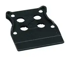
Female Connectors, Double-Row Pin Spacing: 3.5 mm 282[4] _MCS_ MINI HD

- Universal connection for all conductor types

- Unique, compact, double-row connector system for conductor cross sections up to 1.5 mm[2 ]

- High-density, “wire-to-board” connectors for use in very confined spaces

- Centered strain relief plate anchors conductors, while acting as convenient connection and disconnection handle. It also provides easy access to operating slots — even when wired.

- Optional dual-purpose lever doubles as a lock and disconnection aid, while preventing accidental disconnection in closed position

- 100% protected against mismating, available with coding fingers

## Technical data:

|Technical data:|||||||
|---|---|---|---|---|---|---|
|Pin Spacing<br>3.5 mm<br>0.138 in.<br>Ratings per<br>IEC/EN 60664-1<br>Overvoltage category<br>III<br>III<br>II<br>Pollution degree<br>3<br>2<br>2<br>Rated voltage<br>80 V<br>160 V<br>250 V|||Derating Curve<br>Current in A<br>713-1103 female connector with 713-1403 male header<br>Pin spacing: 3.5 mm / Conductor size: 1.5 mm2”f-st”<br>Based on: EN 60512-5-2 / Reduction factor: 0.8||||
|Conductor data:<br>Rated surge voltage<br>2.5 kV<br>2.5 kV<br>2.5 kV<br>Nominal current<br>10 A<br>10 A<br>10 A<br>Approvals per<br>UL/CSA<br>Use group UL 1059<br>B<br>C<br>D<br>Rated voltage<br>150 V<br>–<br>–<br>Nominal current UL<br>10 A<br>–<br>–<br>Nominal current CSA<br>10 A<br>–<br>–|||5<br>10<br>15<br>20<br>Ts + ~ ~ ~ ~<br>Fel<br>SA<br>ae<br>te<br>"sr<br>x<br>=<br>.<br>a<br>~y||||
|Connection technology<br>CAGE CLAMP®<br>Conductor size: solid<br>0.08–1.5 mm2<br>Conductor size: fine-stranded<br>0.08–1.5 mm2<br>Conductor size: fine-stranded<br>0.25–1.0 mm2<br>(with insulated ferrule)<br>Conductor size: fine-stranded<br>0.25–1.0 mm2<br>(with uninsulated ferrule)<br>AWG<br>28–16<br>Strip length<br>6–7 mm / 0.24–0.28 in.|||10<br>20<br>30<br>40<br>50<br>60<br>70<br>80<br>90 100105<br>0<br>Ambient operating temperature in °C<br>Conductor rated current<br>6-, 16-, 24-, 36-pole||||
|Material data:|||_MCS_MINI HD accessories:|Pages:|||
|Material group<br>II<br>Insulating material<br>Glass fiber-reinforced polyamide 6.6 (PA 6.6-GF)<br>Flammability rating per UL 94<br>0V<br>Lower/Upper limit temperature<br>-60 °C / +100 °C<br>Clamping spring material<br>Chrome nickel spring steel (CrNi)<br>Contact material<br>Copper alloy<br>Contact plating<br>tin-plated<br>MCS connectors are also available upon request with gold-plated or partially gold-plated contact surfaces.<br>Dependingon the version requested, “item no. suffix . . ./010-000”is added to the “basic item no.”|||Marking accessories<br>Operating tools<br>Direct marking<br>Strain relief plates|570 – 573<br>296<br>297<br>296|||


_MCS — MULTI CONNECTION SYSTEM_ includes connectors without breaking capacity in accordance with DIN EN 61984.

When used as intended, these connectors shall not be connected/disconnected when live or under load. The circuit design should ensure header pins, which can be touched, are not live when unmated.

Additional approvals and corresponding ratings can be found at www.wago.com. For additional technical information, see Section 13.

Female Connectors, Double-Row _MCS_ MINI HD

> [4] 283

4

## "

**==> picture [504 x 58] intentionally omitted <==**

**----- Start of picture text -----**<br>
With levers With screw flanges<br>Pin spacing: 3.5 mm / 0.138 in.<br>Pin spacing: 3.5 mm / 0.138 in. Pin spacing: 3.5 mm / 0.138 in.<br>0.08–1.5 mm [2] 28–16 AWG 0.08–1.5 mm [2] 28–16 AWG 0.08–1.5 mm [2] 28–16 AWG<br>160 V/2.5 kV/2  10 A 150 V/10 A 160 V/2.5 kV/2  10 A 150 V/10 A 160 V/2.5 kV/2  10 A 150 V/10 A<br>**----- End of picture text -----**<br>


L = [(pole no./2) – 1] x pin spacing + 5.2 mm Oo Coding finger

L = [(pole no./2) – 1] x pin spacing + 12.2 mm

L = [(pole no./2) – 1] x pin spacing + 13.6 mm

|Pole No.<br>Item No.<br>Pack. Unit|Pole No.<br>Item No.<br>Pack. Unit|Pole No.<br>Item No.<br>Pack. Unit<br>Female connector with screw flanges, double-row,|
|---|---|---|
|Female connector, double-row,<br>black<br>Female connector with levers, double-row,<br>black<br>Female connector with screw flanges, double-row,<br>black<br>6  (3x2)<br>713-1103<br>100<br>6  (3x2)<br>713-1103/037-000<br>50<br>6  (3x2)<br>713-1103/107-000<br>50<br>8  (4x2)<br>713-1104<br>50<br>8  (4x2)<br>713-1104/037-000<br>50<br>8  (4x2)<br>713-1104/107-000<br>50<br>10  (5x2)<br>713-1105<br>50<br>10  (5x2)<br>713-1105/037-000<br>50<br>10  (5x2)<br>713-1105/107-000<br>25<br>12  (6x2)<br>713-1106<br>50<br>12  (6x2)<br>713-1106/037-000<br>25<br>12  (6x2)<br>713-1106/107-000<br>25<br>14  (7x2)<br>713-1107<br>50<br>14  (7x2)<br>713-1107/037-000<br>25<br>14  (7x2)<br>713-1107/107-000<br>25<br>16  (8x2)<br>713-1108<br>25<br>16  (8x2)<br>713-1108/037-000<br>25<br>16  (8x2)<br>713-1108/107-000<br>25<br>18  (9x2)<br>713-1109<br>25<br>18  (9x2)<br>713-1109/037-000<br>25<br>18  (9x2)<br>713-1109/107-000<br>25<br>20 (10x2)<br>713-1110<br>25<br>20 (10x2)<br>713-1110/037-000<br>20<br>20 (10x2)<br>713-1110/107-000<br>20<br>22 (11x2)<br>713-1111<br>25<br>22 (11x2)<br>713-1111/037-000<br>20<br>22 (11x2)<br>713-1111/107-000<br>20<br>24 (12x2)<br>713-1112<br>25<br>24 (12x2)<br>713-1112/037-000<br>20<br>24 (12x2)<br>713-1112/107-000<br>20<br>26 (13x2)<br>713-1113<br>25<br>26 (13x2)<br>713-1113/037-000<br>20<br>26 (13x2)<br>713-1113/107-000<br>20<br>28 (14x2)<br>713-1114<br>20<br>28 (14x2)<br>713-1114/037-000<br>20<br>28 (14x2)<br>713-1114/107-000<br>20<br>30 (15x2)<br>713-1115<br>20<br>30 (15x2)<br>713-1115/037-000<br>20<br>30 (15x2)<br>713-1115/107-000<br>20<br>32 (16x2)<br>713-1116<br>20<br>32 (16x2)<br>713-1116/037-000<br>20<br>32 (16x2)<br>713-1116/107-000<br>10<br>34 (17x2)<br>713-1117<br>20<br>34 (17x2)<br>713-1117/037-000<br>10<br>34 (17x2)<br>713-1117/107-000<br>10<br>36 (18x2)<br>713-1118<br>20<br>36 (18x2)<br>713-1118/037-000<br>10<br>36 (18x2)<br>713-1118/107-000<br>10|||


## Male Headers with Solder Pins, Double-Row Pin Spacing: 3.5 mm 284[4] _MCS_ MINI HD

- Male headers may be mounted horizontally or vertically via straight or angled solder pins

- Header housing is molded of THR-compatible insulation material for lead-free reflow soldering

- Separated pin slots prevent damage and make the headers touch-proof when unplugged

- 100% protected against mismating

- Coding pins available

## Technical data:

|Technical data:||||||||
|---|---|---|---|---|---|---|---|
|Pin Spacing<br>3.5 mm<br>0.138 in.<br>Ratings per<br>IEC/EN 60664-1<br>Overvoltage category<br>III<br>III<br>II<br>Pollution degree<br>3<br>2<br>2<br>Rated voltage<br>80 V<br>160 V<br>250 V||||Derating Curve<br>Current in A<br>713-1103 female connector with 713-1403 male header<br>Pin spacing: 3.5 mm / Conductor size: 1.5 mm2”f-st”<br>Based on: EN 60512-5-2 / Reduction factor: 0.8||||
|Rated surge voltage<br>2.5 kV<br>2.5 kV<br>2.5 kV<br>Nominal current<br>10 A<br>10 A<br>10 A<br>Approvals per<br>UL/CSA<br>Use group UL 1059<br>B<br>C<br>D<br>Rated voltage<br>150 V<br>–<br>–<br>Nominal current UL<br>10 A<br>–<br>–<br>Nominal current CSA<br>12 A<br>–<br>–<br>Solder pin data:||||5<br>10<br>15<br>20<br>Ts + ~ ~ ~ ~<br>Fel<br>SA<br>ae<br>te<br>"sr<br>—<br>=<br>.<br>a<br>~y||||
|Solder pin: length/width<br>3.8 mm / 0.8 x 0.8 mm<br>Solder pin: drilled hole diameter<br>1.2+0.1mm||||10<br>20<br>30<br>40<br>50<br>60<br>70<br>80<br>90 100105<br>0<br>Ambient operating temperature in °C<br>Conductor rated current<br>6-, 16-, 24-, 36-pole||||
|For otherpin lengths, please contact factory.||||||||
|Material data:||||_MCS_MINI HD accessory:||Page:||
|Material group<br>I<br>Insulating material<br>Glass-fiber-reinforced polyphthalamide (PPA-GF)<br>Flammability rating per UL 94<br>0V<br>Lower/Upper limit temperature<br>-60 °C / +100 °C<br>Contact material<br>Electrolytic copper (ECu)<br>Contact plating<br>tin-plated<br>MCS connectors are also available upon request with gold-plated or partially gold-plated contact surfaces.<br>Dependingon the version requested, “item no. suffix . . ./010-000”is added to the “basic item no.”||||Coding pin carrier||297||


_MCS — MULTI CONNECTION SYSTEM_ includes connectors without breaking capacity in accordance with DIN EN 61984.

When used as intended, these connectors shall not be connected/disconnected when live or under load. The circuit design should ensure header pins, which can be touched, are not live when unmated.

Additional approvals and corresponding ratings can be found at www.wago.com. For additional technical information, see Section 13.

> [4] 285

4

## Male Headers with Solder Pins, Double-Row _MCS_ MINI HD

With straight solder pins Pin spacing: 3.5 mm / 0.138 in. 160 V/2.5 kV/2  10 A 150 V/10 A

With angled solder pins Pin spacing: 3.5 mm / 0.138 in. 160 V/2.5 kV/2  10 A 150 V/10 A

**==> picture [223 x 11] intentionally omitted <==**

**----- Start of picture text -----**<br>
2,6 2,6 2,6 2,6<br>**----- End of picture text -----**<br>


L = [(pole no./2) – 1] x pin spacing + 5.2 mm

|Pole No.<br>Item No.<br>Pack. Unit|Pole No.<br>Item No.<br>Pack. Unit|
|---|---|
|Male header with straight solder pins, double-row,<br>black<br>6  (3x2)<br>713-1403<br>100<br>8  (4x2)<br>713-1404<br>50<br>10  (5x2)<br>713-1405<br>50<br>12  (6x2)<br>713-1406<br>50<br>14  (7x2)<br>713-1407<br>50<br>16  (8x2)<br>713-1408<br>25<br>18  (9x2)<br>713-1409<br>25<br>20 (10x2)<br>713-1410<br>25<br>22 (11x2)<br>713-1411<br>25<br>24 (12x2)<br>713-1412<br>25<br>26 (13x2)<br>713-1413<br>25<br>28 (14x2)<br>713-1414<br>20<br>30 (15x2)<br>713-1415<br>20<br>32 (16x2)<br>713-1416<br>20<br>34 (17x2)<br>713-1417<br>20<br>36 (18x2)<br>713-1418<br>20|Male header with angled solder pins, double-row,<br>black<br>6  (3x2)<br>713-1423<br>100<br>8  (4x2)<br>713-1424<br>50<br>10  (5x2)<br>713-1425<br>50<br>12  (6x2)<br>713-1426<br>50<br>14  (7x2)<br>713-1427<br>50<br>16  (8x2)<br>713-1428<br>25<br>18  (9x2)<br>713-1429<br>25<br>20 (10x2)<br>713-1430<br>25<br>22 (11x2)<br>713-1431<br>25<br>24 (12x2)<br>713-1432<br>25<br>26 (13x2)<br>713-1433<br>25<br>28 (14x2)<br>713-1434<br>20<br>30 (15x2)<br>713-1435<br>20<br>32 (16x2)<br>713-1436<br>20<br>34 (17x2)<br>713-1437<br>20<br>36 (18x2)<br>713-1438<br>20|


## Accessories Strain Relief Plates and Operating Tool 296[4] _MCS_ MINI HD

Strain relief plates Strain relief plates, Operating tool for in-the-field assembly factory-assembled for female connectors with CAGE CLAMP[®] for female connectors with CAGE CLAMP[®] with partially insulated shaft Type 1 ~~| a~~ 6 / Width Item No. Pack. Unit Width Pole No. Item No. Suffix: Color Item No. Pack. Unit Strain relief plate, Strain relief plate, pre-assembled Operating tool with partially insulated shaft, black type 1, (2.5 x 0.4) mm blade 11 mm 713-126 100 (4 x 25) 11 mm 6–12 . . . /032-000 210-719 1 25 mm 713-127 100 (4 x 25) 25 mm 14–20 . . . /033-000 39 mm 713-128 100 (4 x 25) 39 mm 22–28 . . . /034-000 53 mm 713-129 100 (4 x 25) 53 mm 30–36 . . . /035-000 Ordering example: Female connector, 3.5 mm pin spacing, 20-pole, black with strain relief plate: 713-1110/033-000 An “item no. suffix”, referring to the width of the strain relief plate, is added to the “basic item no.” and determines the type of female connector. > 3 < <_______[B] _______> > D < >3,5< ~~meet~~ The arrangement of the attachments for cable ties allows single conductors or multi-core cables to be secured in Strain Relief Housing Dimensions different ways. Pole No. B H D The width of the cable tie must correspond to the hole dimensions in the drawing for the strain relief plates. 6–12 11 38.7 3 14–20 25 43.7 4.2 WAGO does not offer the recommended cable ties and 22–28 39 48.7 4.2 cable binding tools; those are available from suppliers 30–36 53 54.2 4.9 such as Hellermann. ~~See~~

> [4] 297

## Accessories Coding Pin Carrier and Direct Marking _MCS_ MINI HD

Coding pin carrier for male headers

Item No. Pack. Unit Coding pin carrier with six coding pins 714-101 100 (4 x 25)

Direct marking _MCS_ MINI HD

**==> picture [95 x 8] intentionally omitted <==**

**----- Start of picture text -----**<br>
Direct Marking  MCS  MINI HD<br>**----- End of picture text -----**<br>


713 Series female connectors can be marked with “1 – pole no.” via factory direct printing

Two standard marking orientations are available: 1. Marking perpendicular to conductor entry 2. Marking parallel to conductor entry

Other custom marking options are available upon request.

WAGO recommends pole marking on the PCB for 713 Series male headers.

Direct marking 1 – pole no. of female connectors for conductor termination

Marking Perpendicular to Conductor Entry Item No. Suffix:   /. . . - 047 Ordering examples: Female connector, double-row, 3.5 mm pin spacing, 16-pole, black: 713-1108/000-0047

Female connector with screw flanges, double-row, 3.5 mm pin spacing, 16-pole, black: 713-1108/000-0047

Female connector with levers and strain relief plate, double-row, 3.5 mm pin spacing, 16-pole, black: 713-1108/037-047/033-000

4

The marking type is always defined by the second 4-digit block of the item no. suffix for items with standard colors and materials.

Example: 713-1110/. . . - xxxx xxxx = Item no. suffix for direct pole marking

Marking parallel with Conductor Connection Additional Item No.:   /. . . - 9037

Ordering examples: Female connector, double-row, 3.5 mm pin spacing, 16-pole, black: 713-1108/000-9037

Female connector with levers, double-row, 3.5 mm pin spacing, 16-pole, black: 713-1108/037-9037

Coding a male header. Coding a female connector.

Female connector with strain relief plate, double-row, 3.5 mm pin spacing , 16-pole, black: 713-1108/033-9037

Female Connectors with Push-Buttons Pin Spacing: 3.5 mm 300[4] _MCS_ MINI SL

- Female connectors terminate both solid and ferruled, fine-stranded conductors via simple push-in terminations.

- Integrated push-buttons provide convenient, tool-free operation

- Ultra-low profile at just 7.8 mm, for conductor size up to 1.5 mm[2]

- Coding and testing options available

## Technical data:

|Technical data:||||
|---|---|---|---|
|Pin Spacing<br>3.5 mm<br>0.138 in.||||
|Rating per<br>IEC/EN 60664-1<br>Overvoltage category<br>III<br>III<br>II<br>Pollution degree<br>3<br>2<br>2<br>Rated voltage<br>160 V<br>160 V<br>320 V<br>Rated surge voltage<br>2.5 kV<br>2.5 kV<br>2.5 kV<br>Nominal current<br>8 A<br>8 A<br>8 A||||
|Approvals per<br>UL/CSA<br>Use group UL 1059<br>B<br>C<br>D<br>Rated voltage<br>150 V<br>–<br>–<br>Nominal current UL<br>8 A<br>–<br>–<br>Nominal current CSA<br>–<br>–<br>–||||
|Conductor data:||||
|_MCS_MINI SL accessories:<br>Pages:<br>Marking accessories<br>570 – 573<br>Operating tool<br>301<br>Direct marking<br>301<br>Test pin<br>568<br>Connection technology<br>CAGE CLAMP®S<br>Conductor size: solid<br>0.2–1.5 mm2<br>Conductor size: fine-stranded<br>0.2–1.5 mm2<br>Conductor size: fine-stranded<br>0.25–0.75 mm2<br>(with insulated ferrule)<br>Conductor size: fine-stranded<br>0.25–1.5 mm2<br>(with uninsulated ferrule)<br>AWG<br>24–16<br>Strip length<br>9–10 mm / 0.35–0.39 in.<br>Material data:<br>Material group<br>I<br>Insulating material<br>Polyamide 6.6 (PA 6.6)<br>Temperature stability<br>-60 °C to +100 °C<br>Flammability rating per UL 94<br>0V<br>Clamping spring material<br>Chrome nickel spring steel (CrNi)<br>Contact material<br>Copper alloy<br>Contact plating<br>tin-plated<br>_MCS — MULTI CONNECTION SYSTEM_includes connectors without breaking capacity in accordance with<br>~~———~~<br>~~==>~~||||
|DIN EN 61984.||||


When used as intended, these connectors shall not be connected/disconnected when live or under load. The circuit design should ensure header pins, which can be touched, are not live when unmated.

Additional approvals and corresponding ratings can be found at www.wago.com.

*CSA approval pending For additional technical information, see Section 13.

> [4] 301

**==> picture [529 x 477] intentionally omitted <==**

**----- Start of picture text -----**<br>
Female Connectors with Push-Buttons  !<br>MCS  MINI SL<br>Operating tool (screwdriver),  Direct marking<br>Pin spacing: 3.5 mm / 0.138 in.<br>with partially insulated shaft,  1 – pole no.<br>0.2–1.5 mm [2] 24–16 AWG for female connectors of female connectors<br>for conductor termination<br>160 V/2.5 kV/2  8 A 150 V/8 A<br>ee<br>ee<br>g¢ /e2<br>Pole No. Item No.  Pack. Unit Color Item No.  Pack. Unit Marking Perpendicular to Conductor Entry Item No. Suffix:   /. . . - 047<br>Female connector with push-buttons,  Operating tool (screwdriver), with partially<br>Ordering example:<br>black insulated shaft, type 1, (2.5 x 0.4) mm blade<br> 2 714-102 200 210-719 1 Female connector with push-buttons,<br> 3  714-103 200 3.5 mm pin spacing, 6-pole,<br> 4  714-104 200 black: 714-106/000-047<br> 5  714-105 100<br> 6  714-106 100<br> 8  714-108 100<br>10 714-110 100<br>12  714-112 100<br>14  714-114 50<br>15  714-115 50<br>16  714-116 50<br><________ L ________> <_______ 23 ________><br><___ 16,5 ___><br>> <___ 2,1 > 3,5<br>moe) fl<br>><br>7,8<br><<br>><br>**----- End of picture text -----**<br>


4

L = (pole no. – 1) x pin spacing + 4.2 mm Coding finger

For other lengths, please contact factory.

## Male Headers with Solder Pins Pin Spacing: 3.5 mm 302[4] _MCS_ MINI SL

- Male headers may be mounted horizontally or vertically via straight or angled solder pins

- Header housing is molded of THR-compatible insulation material for

- reflow soldering

- Separated pin slots prevent damage and make the headers touch-proof when unplugged

- Coding pins available

Technical data:

3.5 mm Pin Spacing 0.138 in. Rating per IEC/EN 60664-1 Overvoltage category III III II Pollution degree 3 2 2 Rated voltage 160 V 160 V 320 V Rated surge voltage 2.5 kV 2.5 kV 2.5 kV Nominal current 8 A 8 A 8 A Approvals per UL/CSA Use group UL 1059 B C D Rated voltage 150 V – – Nominal current UL 8 A – – ~~=o~~ Nominal current CSA – – – Solder pin data: Solder pin: length/width 3.4 mm / 0.8 x 0.8 mm Solder pin: drilled hole diameter 1.2[+0.1] mm ~~Oo~~ Material data: _MCS_ MINI SL accessory: Page: Material group I Insulating material Glass-fiber-reinforced polyphthalamide (PPA-GF) Coding pin carrier 303 Temperature stability -60 °C to +115 °C Flammability rating per UL 94 0V Contact material Electrolytic copper (ECu) Contact plating tin-plated ~~——~~ _MCS — MULTI CONNECTION SYSTEM_ includes connectors without breaking capacity in accordance with DIN EN 61984. When used as intended, these connectors shall not be connected/disconnected when live or under load. The circuit design should ensure header pins, which can be touched, are not live when unmated.

Additional approvals and corresponding ratings can be found at www.wago.com.

*CSA approval pending For additional technical information, see Section 13.

> [4] 303

**==> picture [529 x 355] intentionally omitted <==**

**----- Start of picture text -----**<br>
Male Headers with Solder Pins<br>MCS  MINI SL<br>With straight solder pins With angled solder pins Coding pin carrier<br>Pin spacing: 3.5 mm / 0.138 in. Pin spacing: 3.5 mm / 0.138 in.<br>for male headers<br>160 V/2.5 kV/2  8 A 150 V/8 A 160 V/2.5 kV/2  8 A 150 V/8 A<br>eeee<br>_><_________ <____2,45 L  _________> ><_________ <____2,45 L  ________________><br>> 3,5<br>i‘ _> <___0,8 om 0,8 > 3,5 <_ 8  __> |<br>> ><br>6,9  > > 6,9  ><br>3 3<br> <  0,8__> <  ><br>> > 3,4<br>><br>><br>3,4<br> _> > _><br>9,7 9,7<br><_  <_<br>><br><___ ><br>><br>**----- End of picture text -----**<br>


4

L = (No. of poles -1) x pin spacing + 4.9 mm

|Pole No.<br>Item No.<br>Pack. Unit|Pole No.<br>Item No.<br>Pack. Unit|Item No.<br>Pack. Unit|
|---|---|---|
|Male header with straight solder pins,<br>black<br>2<br>714-132<br>200<br>3<br>714-133<br>200<br>4<br>714-134<br>200<br>5<br>714-135<br>200<br>6<br>714-136<br>200<br>8<br>714-138<br>200<br>10<br>714-140<br>100<br>12<br>714-142<br>100<br>14<br>714-144<br>100<br>15<br>714-145<br>100<br>16<br>714-146<br>100|Male header with angled solder pins,<br>black<br>2<br>714-162<br>200<br>3<br>714-163<br>200<br>4<br>714-164<br>200<br>5<br>714-165<br>200<br>6<br>714-166<br>200<br>8<br>714-168<br>200<br>10<br>714-170<br>100<br>12<br>714-172<br>100<br>14<br>714-174<br>100<br>15<br>714-175<br>100<br>16<br>714-176<br>100|Coding pin carrier with six coding pins<br>714-101<br>100 (4 x 25)|


For other lengths, please contact factory.
Updated at June 9, 2026
For over six decades, WAGO has been a pioneering force in electrical engineering and automation, globally recognized for inventing the revolutionary spring CAGE CLAMP® technology. By leading the way in Spring Pressure Connection Technology, WAGO provides secure, maintenance-free connections that significantly reduce wiring time while ensuring consistent contact reliability that is independent of operator skill. Our extensive WAGO portfolio focuses heavily on their industry-leading interconnection solutions. We offer a vast array of DIN rail terminal blocks, wire-to-board terminal blocks, and pluggable terminal block headers and sockets. To support these core components, our selection also includes hundreds of essential terminal block accessories, markers, and specialized fused terminal blocks, ensuring you have everything required for safe and efficient wiring. Beyond foundational connectivity, WAGO excels in interface and automation technology. Our catalog features a curated selection of WAGO power relays, AC/DC converters, and process controllers. From robust power distribution to sophisticated system interlinks, WAGO delivers the meticulously engineered components necessary to build highly reliable, future-ready industrial solutions.
About Novapart
Novapart is a B2B electronic component broker specialising in stock shortages and cost reduction. We source hard-to-find parts and identify compliant alternatives across a catalogue of 410,000+ components from 500+ manufacturers.
Learn more →Stock Shortage Specialist
When a component is unavailable, discontinued or has an unacceptable lead time, we tap into our network of vetted European and Asian distributors to source what you need — without compromising on quality or traceability.
Request a quote →Compliant Alternatives
We identify pin-to-pin, electrically equivalent substitutes that meet the same certifications (RoHS, AEC-Q100, REACH) as your original specification — validated against datasheets, not just part numbers. Often at a lower cost.
BOM Analysis service →