
Image not available
Illustrative purposes only

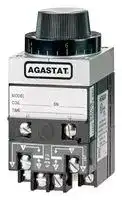
7012L8DN
TIME DELAY RELAY, DPDT, 5S-50S, PANEL
⚠️ Reference pricing provided. In case of supply shortages, we will connect you with our trusted procurement partners to ensure your project's continuity.
- Manufacturer: Amp
- Product type: Time Delay Relays - Electromechanical
- Time Max: 50s
- Time Min: 5s
- Product Range: 7000 Series
- Relay Mounting: Panel Mount
- Relay Terminals: Screw
- Timing Adjustment: Knob
- Contact Configuration: DPDT
| Delivery and price | |
|---|---|
| Units per pack | 10 |
| Price | 783.73 € |
| Current stock | 10+ |
| Lead time | 7 days |
Datasheet

Specialty Relays

## **AGASTAT 7000 Series, Industrial Electropneumatic Timing Relay**

## **Design & Construction**

## **On-delay model 7012 (delay on pickup)**

There are three main components of Applying voltage to the coil (L1-L2) for < Series 7000 Timing Relays:

Applying voltage to the coil (L1-L2) for at least 50 msec starts a time delay lasting for the preset time.  During this pe ri od the nor mal ly closed con tacts (3-5 and 4-6) re main closed.  At the end of the delay period the nor mal ly closed contacts break and the normally open contacts (1-5 and 2-6) make.  The con tacts re main in this trans ferred po si tion until the coil is deenergized, at which time the switch re turns to its orig i nal position.

**Timing Head** cir cu lates air through a vari able length to provide linearly adjustable timing. Pat ent ed design provides easy ad just ment and long service life under severe operating con di tions.

**Precision-Wound Potted Coil** Total sealing without external leads eliminates moisture prob lems, gives maximum insulation value.

**Snap-Action Switch Assembly** — custom-de signed over-center mechanism provides snap action.  Standard switches are DPDT arrangement.

De-energizing the coil, either dur ing or after the de lay pe ri od, will re cy cle the unit within 50 msec.

## **Product Facts**

- n **Available in on-delay, true off-delay, and on/off-delay**

Each of these subassemblies forms self-con tained mod ules assembled at the factory with the other two to afford a wide choice of operating types, coil voltages, and timing ranges.

It will then pro vide a full delay period upon re-energization, re gard less of how often the coil voltage is in ter rupt ed before the unit has been per mit ted to "time-out" to its full delay setting.

- n **Timing from 0.1 seconds to 60 minutes, in linear increments**

The squared design with front terminals and rear mounting permits the grouping of Series 7000 units side-by-side in minimum panel space.  Auxiliary switch es may be add ed in the base of the unit, without affecting the overall width or depth.

- n **Oversize adjustment knobs, serrated with high-resolution markings visible from all angles makes the timer easy to set timers**

## **Off-delay model 7022 (delay on dropout)**

Applying voltage to the coil (for at least 50 msec) will transfer the switch, breaking the nor mal ly closed contacts (1-5 and 2-6), and mak ing the nor mal ly open contacts (3-5 and 4-6).  Contacts remain in this transferred position as long as the coil is en er gized.  The time delay be gins immediately upon de-energization. At the end of the de lay period the switch returns to its normal po si tion. Re-energizing the coil during the delay period will im me di ate ly return the timing mechanism to a point where it will provide a full delay period upon sub se quent de-energization.  The switch remains in the transferred position.

- n **Inherent transient immunity**

## **Operation**

> Two basic operating types are available. Vay0} “On-De lay” mod els provide a delay period TOTAL DELAY——AS SET ON DIAL on energization, at the end of which the I switch transfers the load from one set of il contacts to an oth er.  De-energizing the ! unit dur ing the delay period im me di ate ly N ~~i~~ c | I recycles the unit, ready ing it for anotherfull de lay period on re-energization. CONTACTSMAIN (13-- ~~5~~ N)5) ~~.o~~ .(2(4- ~~-~~ 6)6 11 i1

- n **Standard voltages from 6-550VAC and 12-550VDC (special voltages available)**

- n **Available in 2-pole or 4-pole models**

- n **Numerous enclosure options — explosion proof, dust tight, watertight, hermetically-sealed, NEMA 1**

In "Off-Delay" models the switch trans- **dust tight, watertight,** fers the load im me di ate ly upon energiza- **hermetically-sealed,** tion and the delay period does not be gin **NEMA 1** until the unit is de-energized.  At the end n **Auxiliary timed and** of the delay period the switch returns to **instantaneous switches can** its original po si tion.  Re- en er giz ing the unit during the delay period im me di ate ly **be added for greater** resets the timing, ready ing it for another **switching flexibility** full delay period on de-energization. n **Many mounting options —** No power is required during the timing period, providing a true off delay.

- n **Many mounting options — Surface mount, Panel mount, Octal plug-in mounting**

In addition to these basic operating types, “Double-Head” models offer sequential delays on pull-in and drop-out in one unit. With the addition of auxiliary switches the basic models provide twostep timing.

- n **Options: quick-connect terminals, dial stops, and transient pro tec tion module**

**Note: Seismic & radiation tested E7000 models are available. Consult factory for detailed in for ma tion.**

- n **Easy-to-reach screw terminals, all on the face of the unit, clearly identified**

- n **Modular assembly — timing head, coil as sem bly and switchblock are all individual modules, with switches field-replaceable**

- n **File E15631, File LR29186**

**Note:** 7032 types and certain models with accessories are not agency approved. Users should thoroughly review the technical data before selecting a product part number. It is recommended that users also seek out the pertinent approvals files of the agencies/laboratories and review them to ensure the product meets the requirements for a given application. Consult factory for ordering information.

- **R** for a given application.

- fe) **R** G) @& ce Consult factory for ordering information.

- ~~LE~~

12–8

Catalog 5-1773450-5 Revised 3-13

Dimensions are shown for Dimensions are in millimeters USA: +1 800 522 6752 For additional support numbers reference purposes only. unless otherwise specified. Asia Pacific: +86 0 400 820 6015 please visit www.te.com Specifications subject UK: +44 800 267 666 to change.

www.te.com

Specialty Relays

**12**

## **AGASTAT 7000 Series, Industrial Electropneumatic Timing Relay** (Continued)

## **Auxiliary Switch Options**

To increase the versatility of the basic timer mod els, aux il ia ry switches may be added to either on-delay or off-delay types.  They switch additional circuits, pro vide two-step timing action, or furnish electrical in ter lock for sus tained coil energization from a momentary impulse, depending on the type selected and its ad just ment.  They are installed at the factory.  All aux il ia ry switches are SPDT with UL listings of 10A @ 125, 250, or 480 VAC.  A maximum of one Code T or two Code L auxiliary switch es may be added to each relay.  The L or LL switch is available with on-delay relays only.  The T switch is available with both the on-delay and off-de lay relays.

## **Auxiliary Switch Options for On-Delay**

## **Instant Transfer (Auxiliary Switch Code L, max i mum of 2 per relay.)**

1. Energizing coil begins time delay and transfers aux il ia ry switch.

2. Main switch transfers after total preset delay.

3. De-energizing coil resets both switches instantly.

Auxiliary switch is nonadjustable.

**Two-Step Timing (Auxiliary Switch Code T,  max i mum of 1 per relay.)**

1. Energizing coil begins time delay.

2. After first delay auxiliary switch transfers.

3. Main switch transfers after total preset delay.

4. De-energizing coil resets both switches instantly.  First delay is independently adjustable, up to 30% of over all delay.  (Rec om mend ed maximum 100 sec onds.)

## **Auxiliary Switch Options for Off-Delay**

In these models the same auxiliary switch provides ei ther two-step timing or instant transfer action, de pend ing on the ad just ment of the actuator.

**Two-Step Timing (Auxiliary Switch**

**Code T, max i mum of 1 per relay.)**

1. Energizing coil transfers main and auxiliary switch es in stant ly.

2. De-energizing coil begins time delay.

3. After first delay auxiliary switch transfers.

4. Main switch transfers after total preset delay.  First delay is independently adjustable, up to 30% of over all delay.  (Rec om mend ed maximum 100 sec onds.)

**Instant Transfer (Auxiliary Switch Code L, max i mum of 1 per relay.)**

1. Energizing coil transfers main and auxiliary switch es in stant ly.

2. De-energizing coil resets auxiliary switch and be gins time delay.

3. Main switch transfers after total preset delay.

- Auxiliary switch is factory adjusted to give instant trans fer op er a tion.  Two-step timing may be set at the factory to customer specification up to a 3:2 ratio.

## **On-delay, Off-delay Model 7032 (Double Head)**

The Double Head model provides delayed switch trans fer on energization of its coil, and de layed resetting upon coil deenergization.  Each delay period is in de pen dent ly adjustable. In new circuit designs or the improvement of ex ist ing con trols now using two or more conventional tim ers, the Double Head unit offers distinct advantages.

Its compact design saves panel space, while the simplified wiring reduces costly in ter con nec tion.

## **On-delay Model 7014, Off-delay Model 7024**

With the addition of an extra switch block at the bot tom of the basic unit, this version of the Series 7000 offers four pole switch capacity with simul taneous tim ing or two-step timing.  The two-step operation is achieved by factory adjustment to your specifications.

For two-step operation, a maximum timing ratio be tween upper and lower switches of 3:2 is rec om mend ed.  Once ad - just ed at the factory, this ratio remains con stant regardless of changes in dial settings. (Ex: If up per switch transfer is set on dial at 60 sec., minimum time on lower switch should be 40 sec.)

This Series 7000 unit offers many of the per for m ance features found in basic models — voltage ranges, timing and switch capacities.

Four pole models add approximately 1-1/4" to the max i- mum height of the basic model, approximately 1/8" to the depth. They are designed for vertical op er a tion only.

12–9 For additional support numbers please visit www.te.com

Catalog 5-1773450-5 Dimensions are shown for Dimensions are in millimeters USA: +1 800 522 6752 Revised 3-13 reference purposes only. unless otherwise specified. Asia Pacific: +86 0 400 820 6015 Specifications subject UK: +44 800 267 666 www.te.com to change.

www.te.com

Specialty Relays

## **AGASTAT 7000 Series, Industrial Electropneumatic Timing Relay** (Continued)

## **Surge/Transient Protection Option**

The Surge/Transient Protection Option pro tects elec tron ic con trol cir cuits from tran sients and surg es which are gen er at ed when the timer coil is ac ti vat ed.  The de vice is not po lar i ty sen si tive and permits the user to ini tiate, delay, sequence and pro gram equip ment ac tions over a wide range of ap pli ca tions under the most se vere operating con di tions. The varistor will not affect the operating characteristics  of

## **Product Facts**

   - n **Protect electronic control circuits from voltage transients generated by the timer coil**

- n **Fast response to the rapidly** the 7000 Tim er.  The varistor has bilateral and symmetrical

- **rising back E.M.F.**

- @oo. voltage and current characteristics.

   - n **High performance clamping voltage char ac ter is tics**

**Transient Suppressor Option "V"**

- n **UL recognized, (except varistor and coil together).**

- n **Timer NOT polarity sensitive**

**Timing Specifications** (All values shown are at nominal voltage and 25°C unless otherwise specified)

## **Operating Modes** —

Model 7012/7014 — On-delay (delay on pick-up). Model 7022/7024 — Off-delay (delay on drop-out). Model 7032 — On-delay, off-delay (double head).

**Timing Adjustment** — Timing is set by simply turning the dial to the desired time value.  In the zone of approximately 25° sep a rat ing the  high and low end of timing ranges A,D,E, and K, in stan ta neous operation (no time delay) will occur. All other ranges produce an infinite time de lay when the dial is set in this zone.

Models 7014 and 7032 are available with letter dials only. The upper end of the time ranges in these models may be twice the values shown.

## **Linear Timing Ranges** —

|**Code**|**Models 7012,**<br>**7022, 7024**|**Models 7014,**<br>**7032**|**Models 7014,**<br>**7032**|
|---|---|---|---|
|A|.1 to 1 Sec.|.2 to 2 Sec.||
|B|.5 to 5 Sec.|.7 to 7 Sec.||
|C|1.5 to 15 Sec|2 to 20 Sec.|2 to 20 Sec.|
|D|5 to 50 Sec.|10 to 100 Sec.|10 to 100 Sec.|
|E|20 to 200 Sec.|30 to 300 Sec.|30 to 300 Sec.|
|F|1 to 10 Min.|1.5 to 15 Min.||
|H|3 to 30 Min.|3 to 30 Min.||
|I|6 to 60 Min.||Not Avail.|
|J|3 to 120 Cyc.||Not Avail.|
|K|1 to 300 Sec.||Not Avail.|
|**Repeat Accuracy **—||||
|For delays of 200 seconds or less:||7012*,7022,7024:|±5%|
|||7014*:|±10%|
|||7032:|±15%|
|For delays greater than 200 seconds:<br>7012*,7022,7014*,7024:<br>±10%||||
|||7032:|±15%|


- The first time delay afforded by Model 7012 with H (3 to 30 min.) and I (6 to 60 min.) time ranges or Model 7014 with H time range will be approx. 15% long er than sub se quent delays due to coil temperature rise.

- **Reset Time** — 50 msec. (except model 7032)

**Relay Release Time** — 50 msec. for on-delay models (7012/7014)

## **Operating Voltage Coil Data (for DPDT)**

||||**Operating***||**Operating**|
|---|---|---|---|---|---|
|**Coil**|**Code**|**Rated**|**Voltage**|**Rated**|**Voltage**|
|**Part #**|**Letter**|**Voltage**|**Range**|**Volt age**|**Range**|
||||**@ 60Hz**||**@50Hz**|
|7000|A|120|102-132|110|93.5-121|
||B|240|204-264|220|187-242|
||C|480|408-528|||
||D|550|468-605|||
||E|24|20.5-26.5|||
|AC|F|||127|108-140|
||G|||240|204-264|
||H|12|10.2-13.2|||
||I|6|5.1-6.6|||
||J|208|178-229|||
||K||Dual Voltage Coil<br>(Combines A&B)|||
||L||Special AC Coils<br>(L1,L2,etc.)|||
|7010|M|28|22.4-30.8|||
||N|48|38.4-52.8|||
||O|24|19.2-26.4|||
||P|125|100-137.5|||
||Q|12|9.6-13.2|||
||R|60|48-66|||
|DC|S|250|200-275|||
||T|550|440-605|||
||U|16|12.8-17.6|||
||V|32|25.8-35.2|||
||W|96|76.8-105.6|||
||Y|6|4.8-6.6|||
||Z|220|176-242|||
||X||Special DC Coils<br>(X1, X2, etc.)|||


*Four pole Models:  Operational voltage range 90% to 110% for AC units; 85% to 110% for DC units.

**Relay Operate Time** — 50 msec. for off-delay models (7022/7024)

See next page for more coil data.

12–10 Catalog 5-1773450-5 Revised 3-13

USA: +1 800 522 6752 Asia Pacific: +86 0 400 820 6015 UK: +44 800 267 666

Dimensions are shown for Dimensions are in millimeters reference purposes only. unless otherwise specified. Specifications subject to change.

For additional support numbers please visit www.te.com

www.te.com

Specialty Relays

## **AGASTAT 7000 Series, Industrial Electropneumatic Timing Relay** (Continued)

## **Timing Specifications** (All values shown are at nominal voltage and 25°C unless otherwise specified)

Minimum operating voltages are based on ver ti cal ly mount ed 7012 units.  7012 hor i- zon tal ly mounted or 7022 ver ti cal ly or horizontally mounted units will operate sat isfac to ri ly at minimum voltages approximately 5% low er than those list ed.

AC units drop out at approximately 50% of rated voltage. DC units drop out at ap proxi mate ly 10% of rated voltage.

All units may be operated on intermittent duty cy cles at voltages 10% above the listed maximums (in ter mit tent duty - maximum 50% duty cycle and 30 minutes “on” time.)

## **Surge/Transient Protection Option Characteristics (DC Timers Only)**

|**Coil Voltage**|**Max Excess**|**Max De-energization**|
|---|---|---|
|**Nominal(DC)**|**Energy Capacity (Joule)**|**Tran sient Voltage**|
|12 V|0.4 J|48 V|
|24 V|1.8 J|93 V|
|28 V|1.8 J|93 V|
|32 V|2.5 J|135 V|
|48 V|3.57 J|145 V|
|60 V|6 J|250 V|
|96 V|10 J|340 V|
|110 V|10 J|340 V|
|125 V|10 J|340 V|
|220 V|17 J|366 V|
|250 V|17 J|366 V|


## **Surge Life** —

Applied 100,000 times continuously with the in ter val of 10 seconds at room temperature. Below 68 VAC: 12A; Above 68 VAC: 35A

## **Temperature Range** —

Operating — -22°F to +167°F (-30°C to + 75°C) Storage — -40°F to +167°F (-40°C to +75°C)

**Output/Life Contact Ratings** — Contact Capacity in Amps (Resistive Load)

|**Contact**|**Min. 100,000**|**Min. 1,000,000**|
|---|---|---|
|**Voltage**|**Operations**|**Operations**|
|30 VDC|15.0|7.0|
|110 VDC|1.0|0.5|
|120 V 60Hz|20.0|15.0|
|240 V 60Hz|20.0|15.0|
|480 V 60Hz|12.0|10.0|


**Dielectric** — Withstands 1500 volts RMS 60Hz between terminals and ground. 1,000 volts RMS 60 Hz between non-con nect ed terminals. For dielectric specification on hermetically sealed mod els consult factory.

**Insulation Resistance** — 500 Megohms with 500VDC applied.

## **Temperature Range** —

Operating — -20°F to +165°F (-29°C to 74°C) Storage — -67°F to +165°F (-55°C to 74°C)

**Temperature Variation** — Using a fixed time delay which was set and measured when the ambient temperature was 77°F (25°C), the maximum observed shift in the average of three con sec u tive time de lays was -20% at -20°F (-29°C) and +20% at 165°F (74°C).

**Mounting/Terminals** — Normal mounting of the basic unit is in a vertical po si tion, from the back of the panel. **All units are tested for vertical operation.** Basic models (7012, 7022) may also be horizontally mount ed, and will be adjusted ac cording ly **when Accessory Y1 is spec i fied in your order.**

Standard screw terminals (8-32 truss head screws sup plied) are located on the front of the unit, with per ma nent sche mat ic markings. Barrier isolation is de signed to ac commo date spade or ring tongue ter mi nals, with spacing to meet all industrial control spec i fi ca tions.

The basic Series 7000 may also be panel mounted with the addition of a panel mount kit, X option, that includes all nec es sary hardware and faceplate. This offers the con ve nience of “out-front” adjustment, with large dial skirt knob. The faceplate and knob blend with ad vanced equipment and console designs, while the body of the unit and its wiring are protected behind the panel.

Other mounting options include plug-in styles and special configurations to meet unusual installation re quire ments. Contact factory for details.

**Power Consumption** — Approximately 8 watts power at rated voltage .

|**Approximate Weights**—|
|---|
|Models<br>7012, 7022 . . . . . . . . . . . . . . . . . . . . . . . 2 lbs. 4 ozs.<br>7014, 7024 . . . . . . . . . . . . . . . . . . . . . . 2 lbs. 10 ozs.<br>7032 . . . . . . . . . . . . . . . . . . . . . . . . . . . . 3 lbs. 5 ozs.|
|Weight may vary slightly with coil voltage.|


**12**

10 Amps Resistive, 240 VAC

1/4 Horsepower, 120 VAC/240VAC (per pole)

15 Amps 30 VDC (per pole)

5 Amps, General Purpose, 600VAC (per pole)

12–11

Catalog 5-1773450-5 Dimensions are shown for Dimensions are in millimeters USA: +1 800 522 6752 Revised 3-13 reference purposes only. unless otherwise specified. Asia Pacific: +86 0 400 820 6015 Specifications subject UK: +44 800 267 666 www.te.com to change.

For additional support numbers please visit www.te.com

www.te.com

Specialty Relays

## **AGASTAT 7000 Series, Industrial Electropneumatic Timing Relay** (Continued)

## **Outline Dimensions** (Dimensions in inches)

## **Models 7012, 7022**

## **Models 7014, 7024**

**==> picture [44 x 8] intentionally omitted <==**

**----- Start of picture text -----**<br>
Model 7032<br>**----- End of picture text -----**<br>


**==> picture [23 x 16] intentionally omitted <==**

**----- Start of picture text -----**<br>
199 Dia.<br>**----- End of picture text -----**<br>


## **Panel Mount Option “X”**

## **Surge/Transient Protection Option**

Dimensions are shown for Dimensions are in millimeters reference purposes only. unless otherwise specified. Specifications subject to change.

12–12

Catalog 5-1773450-5 Revised 3-13

USA: +1 800 522 6752 Asia Pacific: +86 0 400 820 6015 UK: +44 800 267 666

For additional support numbers please visit www.te.com

www.te.com

Specialty Relays

## **AGASTAT 7000 Series, Industrial Electropneumatic Timing Relay** (Continued)

## **Ordering Information**

**Typical Part No.** ‰ **70 1 2 A D GZ 1. Basic Series:** 70 = 7000 series electropneumatic timing relay **2. Operation:** 1 = On-delay 3 = On-delay, off-delay  (double head) 2 = Off-delay **3. Contact Arrangement:** 2 = 2PDT (2 form C) **4 = 4PDT (4 form C) **4. Coil Voltage:** AC Coils DC Coils A = 120VAC, 60 Hz.; 110VAC, 50Hz. M = 28VDC B = 240VAC, 60 Hz.; 220VAC, 50Hz. N = 48VDC C = 480VAC, 60 Hz. O = 24VDC D = 550VAC, 60 Hz. P = 125VDC E = 24VAC, 60 Hz. Q = 12VDC F = 127VAC, 50 Hz. R = 60VDC G = 240VAC, 50Hz. S = 250VDC H = 12VAC, 60 Hz. T = 550VDC K = Dual voltage (combines A & B) U = 16VDC L = Special AC coils (L1, L2, etc.) V = 32VDC W = 96VDC Y = 6VDC Z = 220VDC X = Special DC coils (X1, X2, etc.) **5. Timing Range:** Models 7012, 7022 & 7024 †Models 7014 & 7032 A = .1 to 1 sec. For model 7032 specify separate time B = .5 to 5 sec. range code for each head. Example: AB. C = 1.5 to 15 sec. Any two ranges may be selected. D = 5 to 50 sec. A = .2 to 2 sec. E = 20 to 200 sec. B = .7 to 7 sec. F = 1 to 10 min. C = 2 to 20 sec. H = 3 to 30 min. D = 10 to 100 sec. I = 6 to 60 min. E = 30 to 300 sec. J = 3 to 120 cyc. F = 1.5 to 15 min. K = 1 to 300 sec. H = 3 to 30 min. **6. Options:** A1 = Single quick-connect terminals (note 4). l2 = Tamper-proof Cap, transparent (Cannot be combined with Option X). A2 = Double quick-connect terminals (note 4). L = Auxiliary Switch, instant transfer. 7012 only (notes 2 & 6). B = Plug-in connectors (note 4). LL = Two Aux. Switches, instant transfer. On Model 7014 Factory Installed Only. (notes 2 & 6) GZ = Enclosure with bottom knockouts (note 1). M = Dust-tight Gasketing (notes 4 & 5). H2 = Hermetically sealed enclosure, 8 pin solder (notes 1 & 4). P = Octal Plug Adapter. Can be combined only with options l1,l2. M, S, X, or Y1. (note 4). H3 = Hermetically sealed enclosure, 8 pin octal (notes 1 & 4). S = Dial Stops. H4 = Hermetically sealed enclosure, 8 screw terminal block (notes 1 & 4). T = Auxiliary Switch, two-step timing (notes 2 & 6). *H6 = Hermetically sealed enclosure, 11 pin solder (notes 1 & 4). V = Transient/Surge Protection (for DC coil voltage only). *H7 = Hermetically sealed enclosure, 11 pin octal (notes 1 & 4). X = Panelmount includes hardware and adjustment for horizontal operation (note 4) *H8 = Hermetically sealed enclosure, 11 screw terminal block (notes 1 & 4). Y1 = Horizontal testing, for horizontal operation without panel mounting (note 4). l1 = Tamper-proof Cap, opaque black (Cannot be combined with Option X). Y2 = Horizontal testing, with Compensating Spring for vertical operation (note 4).

**12**

Notes:

1. Cannot be combined with B, P or X Options

2. Cannot be combined with B, P or Y2 Options

3. Cannot be combined with GZ, H, l1, l2, K, W or Y1 Options

4. Not Avail. on 4-Pole Models

5. Not Available with L, T or LL options.

6. Not Available on hermetically sealed units.

- Sized to accommodate one L or T Auxiliary Switch

- ** Not available on 7032 model.

- Available with letter graduated dials only. Upper end of time range may be twice the value shown

†† 120 cycles = 2 sec.

## **Our authorized distributors are more likely to maintain the following items in stock for immediate delivery.**

|7012AA|7012AE|7012ACL|7012PB|7012PJ|7022AA|7022AE|7022AJ|7022PA|
|---|---|---|---|---|---|---|---|---|
|7012AB|7012AF|7012BC|7012PC|7012PK|7022AB|7022AF|7022AKT|7022PB|
|7012AC|7012AH|7012NC|7012PD|7012PKX|7022AC|7022AH|7022BC|7022PC|
|7012AD|7012AK|7012PA|7012PF|7012PJX|7022AD|7022AI|7022BK|7022PK|


12–13

Catalog 5-1773450-5 Dimensions are shown for Dimensions are in millimeters USA: +1 800 522 6752 For additional support numbers Revised 3-13 reference purposes only. unless otherwise specified. Asia Pacific: +86 0 400 820 6015 please visit www.te.com Specifications subject UK: +44 800 267 666 www.te.com to change.

www.te.com

Specialty Relays

## **AGASTAT 7000 Series, Industrial Electropneumatic Timing Relay** (Continued)

**==> picture [487 x 326] intentionally omitted <==**

**----- Start of picture text -----**<br>
Ordering Options — Can only be ordered as factory installed options  (Dimensions, where shown, are in inches)<br>A1 – Single Quick-Connect  A2 – Double Quick-Connect B – Plug-In Connectors GZ – Metal En clo sure<br>Ter mi nals Ter mi nals Use with Accessory “C” or “D” below. With knockouts for bottom connection.<br>3.16" W x 3.84" D x 7.63"H<br>| ap / SS<br>H – Hermetically Sealed I – Tamper-Proof Cover L – Auxiliary Switch LL – Auxiliary Switch<br>Enclosure<br>r ws<br>M – Dust tight P – Octal Plug Adapter S – Dial Stops T – Auxiliary Switch<br>Gasket<br>Gasket<br>**----- End of picture text -----**<br>


**V – Transient/Surge Protection X – Panelmount Kit** Mounting hardware included. Transient Protection

**Accessories** (Not available for 7032 models)

## **Plug-In Receptacle (Accessory C)**

## **Plug-In Receptacle (Accessory D)**

Screw Terminals Quick Connect Terminals **Catalog No. 700137** . **Catalog No. 700141** . For use with “B” Option. For use with “B” Option.

**Ordering options can only be ordered as factory installed options.**

12–14

Catalog 5-1773450-5 Revised 3-13

USA: +1 800 522 6752 For additional support numbers Asia Pacific: +86 0 400 820 6015 please visit www.te.com UK: +44 800 267 666

Dimensions are shown for Dimensions are in millimeters reference purposes only. unless otherwise specified. Specifications subject to change.

www.te.com
Updated at February 9, 2023
About Novapart
Novapart is a B2B electronic component broker specialising in stock shortages and cost reduction. We source hard-to-find parts and identify compliant alternatives across a catalogue of 410,000+ components from 500+ manufacturers.
Learn more →Stock Shortage Specialist
When a component is unavailable, discontinued or has an unacceptable lead time, we tap into our network of vetted European and Asian distributors to source what you need — without compromising on quality or traceability.
Request a quote →Compliant Alternatives
We identify pin-to-pin, electrically equivalent substitutes that meet the same certifications (RoHS, AEC-Q100, REACH) as your original specification — validated against datasheets, not just part numbers. Often at a lower cost.
BOM Analysis service →