
Image not available
Illustrative purposes only

68.22.9012.4300
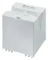
Power Relay, 2NO, 12 VDC, 100 A, 68 Series, Through Hole, Non Latching
⚠️ Reference pricing provided. In case of supply shortages, we will connect you with our trusted procurement partners to ensure your project's continuity.
- Manufacturer: FINDER
- Product type: Power Relays
- SVHC: No SVHC (04-Feb-2026)
- Coil Type: Non Latching
- Coil Voltage: 12VDC
- Product Range: 68 Series
- Relay Mounting: Through Hole
- Coil Resistance: 50ohm
- Contact Current: 100A
- Relay Terminals: PC Pin
- Contact Material: Silver Tin Oxide
- Contact Voltage VAC: 400V
- Contact Voltage VDC: -
- Contact Configuration: 2NO
| Delivery and price | |
|---|---|
| Units per pack | 20 |
| Price | 27.76 € |
| Current stock | 10+ |
| Lead time | 30 days |
Datasheet

68 SЕRIES

## High Power relay 100 A

Power generators Back-up generators

Pump control Disabled lift

Inverter

Charging Stations

FINDER reserves the right to alter characteristics at any time without notice. FINDER assumes no liability for damage to persons or property, caused as a result of the incorrect use or application of its products.

68 SERIES

A

**Printed circuit mount - 3.6 mm contact gap Relay for applications with high power Type 68.22-4300**

## **68.22-4300**

- 2 NO

- Contact gap ≥ 3.6 mm (according to VDE 0126-1-1, EN 62109-1, EN 62109-2)

- DC coils, with only 700 mW holding power

- Reinforced insulation between coil and contacts

- Suitable for use at ambient temperatures up to 85 °C

- Meets the EN 60335-1 requirements of resistance to heat and fire (GWIT 775 °C and GWFI 850 °C)

   - 2 NO

   - Contact gap 3.6 mm

   - PCB mount

- Cadmium free contact materials

|||||<br>|<br>_fg__ _e__)<br>o”<br>24|
|---|---|---|---|
||For outline drawing see page 6||Copper side view|
||**Contact specification**<br>Contact configuration<br>Contactgap<br>Rated current/<br>Maximumpeak current(for 1 ms)|mm<br>A|2 NO<br>≥ 3.6<br>100/300<br>~~PC~~|
||Rated voltage/<br>Maximum switchingvoltage|V AC|400/690|
||Rated load AC1/AC7a (perpole)|VA|40000<br>~~Po~~|
||Rated load AC15 (perpole @ 230 V AC)<br>VA||4600<br>~~Ps~~|
||Single-phase motor rating(230 V AC)<br>Three-phase motor rating(480 V AC)<br>BreakingcapacityDC1: 24/110/220 V<br>Minimum switchingload<br>Standard contact material<br>**Coil specification**<br>Nominal voltage (UN)|kW<br>kW<br>A<br>mW (V/mA)<br>V DC|2.2<br>—<br>A<br>100/5/1.2<br>1000 (10/10)<br>AgSnO2<br>12 - 24<br>~~Ps~~<br>~~PC~~<br>~~PCPs~~|
||Ratedpower|W|2.9<br>~~Pe~~|
||Operatingrange (–40…+70°C)|DC|(0.90 …1.1)UN<br>~~PC~~|
||Energy-saving mode (–40…+85)°C<br>Operatingrange for 1 s||(0.95…2.5)UN|
||Holdingvoltage range|DC|0.5 UN<br>~~Ps~~|
||Minimum holding power|W|0.7<br>~~Ps~~|
||Must drop-out voltage<br>**Technical data**|DC|0.05 UN|
||Mechanical life|cycles|1 · 106|
|X-2021, www.findernet.com|Electrical life at rated load AC7a<br>Operate/release time<br>Ambient temperature range<br>(energy-savingmode)<br>Environmentalprotection<br>**Approvals**(according to type)|cycles<br>ms<br>°C|30 · 103<br>25/3<br>–40…+70(–40…+85)<br>RT II<br>~~PC~~<br>~~Ps~~<br>~~|~~<br>FAL © A\is|


**3**

68 SERIES

## **Ordering information**

Example: 68 series, power relay for printed circuit, 2 NO contacts, 12 V DC coil.

A

**A B C D**

## **6 8 . 2 2 . 9 . 0 1 2 . 4 3**

**0 0**

## **Series**

## **Type**

**A: Contact material** 4 =  Standard AgSnO2

## **D: Special versions**

0 =  Standard

2 =  3-phase PCB terminals,

1.5 mm gap between PCB and relay base

## **No. of poles**

**B: Contact circuit**

3 =  NO, ≥ 3.6 mm contact gap

**C: Options**

0 = None

2 =  2 pole

**Coil version**

9 =  DC

## **Coil voltage**

See coil specifications

## **Technical data**

## **Insulation according to EN 61810-1**

|Nominal voltage of supply system<br>V AC|Nominal voltage of supply system<br>V AC|400/690 3-phase|
|---|---|---|
|Rated insulation voltage<br>V AC||630|
|Pollution degree||3|
|**Insulation between coil and contact set**|||
|Type of Insulation||Reinforced|
|Overvoltage category||III|
|Rated impulse voltage<br>kV (1.2/50 µs)||6|
|Dielectric strength<br>V AC||5000|
|**Insulation between adjacent contacts**|||
|Type of Insulation||Basic|
|Overvoltage category||III|
|Rated impulse voltage<br>kV (1.2/50)µs||6|
|Dielectric strength<br>V AC||4000|
|**Insulation between open contacts**|||
|Type of disconnection||Full-disconnection|
|Overvoltage category||III|
|Rated impulse voltage<br>kV (1.2/50)µs||4|
|Dielectric strength<br>V AC||2500|
|**Insulation between coil terminals**|||
|Rated impulse voltage (surge) differential mode<br>(according to EN 61000-4-5)<br>kV (1.2/50 µs)||4|
|**Other data**|||
|Bounce time: NO<br>ms||2|
|Vibration resistance (10…150)Hz: NO<br>g||9|
|Shock resistance|g|30|
|Power lost to the environment|without contact current<br>W|2.9|
||with rated current<br>W|13|
|Test procedure||B (single mounting)|
|Recommended distance between relays mounted on<br>PCB in case of group mounting<br>mm||≥ 20|
|**Short circuit protection**|||
|Rated conditional short circuit current<br>kA||5|
|Back-up fuse for motor load<br>A||63 (delayed type)|


**4**

68 SERIES

A

## **Contact specification**

## **F 68 - Electrical life v contact current**

**==> picture [216 x 101] intentionally omitted <==**

**----- Start of picture text -----**<br>
AC7a<br>AC1<br>Cycles<br>**----- End of picture text -----**<br>


**NOTE:** for ambient temperatures between 70 and 85 ° C, the electrical life is reduced by 30%

## **H 68 - Maximum DC breaking capacity**

**==> picture [192 x 177] intentionally omitted <==**

**----- Start of picture text -----**<br>
DC1<br>DC13<br>L/R=100 ms<br>DC voltage (V)<br>DC breaking current (A)<br>**----- End of picture text -----**<br>


When switching a resistive (DC1) or inductive (DC13) load having voltage and current values under the corresponding curve, an electrical life of > 30000 cycles can be expected.

**NOTE:** The heating and electrical endurance tests have been performed on relays soldered on PC boards having the following characteristics: double side, copper thickness >105 μm, contact tracks width 40 to 45 mm, total cross section about 10 mm[2]

**5**

68 SERIES

## **Coil specifications**

**DC coil data**

A

|Nominal<br>voltage<br>UN|Coil code|Operating range<br>(@ 70 °C max)<br>Umin<br>Umax|Operating range<br>(@ 70 °C max)<br>Umin<br>Umax|Holding<br>voltage<br>Uh|Resistance<br>R|Rated coil<br>consumption I<br>at UN<br>IN|
|---|---|---|---|---|---|---|
|V||V|V|V|Ω|mA|
|12|**9**.012|10.8|13.2|6.0|50|240|
|24|**9**.024|21.6|26.4|12.0|200|120|


## **R 68-1 -  Operating range v ambient temperature,**

with standard (continuous) coil energization (–40…+70)°C

**==> picture [251 x 138] intentionally omitted <==**

**1 -** Max. permitted coil voltage.

**2 -** Min. pick-up voltage with coil at ambient temperature.

## **R 68-2 -  Operating range v ambient temperature,**

in energy saving mode (–40…+85)°C

**==> picture [252 x 141] intentionally omitted <==**

**----- Start of picture text -----**<br>
Operating range for < 1 s<br>**----- End of picture text -----**<br>


## **Energy saving mode**

In some applications, such as photovoltaic inverters, it may be necessary to minimize the overall relay power dissipation and to permit use at higher ambient temperature levels (up to 85 °C). This can be achieved by initially applying a coil voltage within the Energy saving mode Operating range (see diagram to the left) and then rapidly (< 1 s) reducing the coil voltage to a level within the Holding voltage range. The lower the Holding voltage, the lower is the continuous power dissipation of the coil (0.7 W minimum).

Coil voltages as high as 2.5 UN may be used, when necessary, to reduce the contact operate time.

**1 -** Max. permitted coil voltage.

**2 -** Min. pick-up voltage with coil at ambient temperature.

## **Outline drawings**

Type 68.22

**==> picture [139 x 194] intentionally omitted <==**

Please see general technical information

**6**
Updated at June 7, 2026
About Novapart
Novapart is a B2B electronic component broker specialising in stock shortages and cost reduction. We source hard-to-find parts and identify compliant alternatives across a catalogue of 410,000+ components from 500+ manufacturers.
Learn more →Stock Shortage Specialist
When a component is unavailable, discontinued or has an unacceptable lead time, we tap into our network of vetted European and Asian distributors to source what you need — without compromising on quality or traceability.
Request a quote →Compliant Alternatives
We identify pin-to-pin, electrically equivalent substitutes that meet the same certifications (RoHS, AEC-Q100, REACH) as your original specification — validated against datasheets, not just part numbers. Often at a lower cost.
BOM Analysis service →