
Image not available
Illustrative purposes only

67.22.9.012.4300
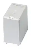
Power Relay, DPST-NO, 12 VDC, 50 A, 67 Series, Through Hole, Non Latching
⚠️ Reference pricing provided. In case of supply shortages, we will connect you with our trusted procurement partners to ensure your project's continuity.
- Manufacturer: FINDER
- Product type: Power Relays
- SVHC: No SVHC (04-Feb-2026)
- Coil Type: Non Latching
- Coil Voltage: 12VDC
- Product Range: 67 Series
- Relay Mounting: Through Hole
- Coil Resistance: 85ohm
- Contact Current: 50A
- Relay Terminals: PC Pin
- Contact Material: Silver Tin Oxide
- Contact Voltage VAC: 400V
- Contact Voltage VDC: -
- Contact Configuration: DPST-NO
| Delivery and price | |
|---|---|
| Units per pack | 100 |
| Price | 30.76 € |
| Current stock | 10+ |
| Lead time | 30 days |
Datasheet

67 SЕRIES

## High Power relay 50 A

Power generators

Back-up generators Pump control

Inverter

Prices, features, specifications, capabilities, appearance and availability of our products and services are subject to change without notice. FINDER assumes no responsibility for the presence of possible errors or insufficient information in this document. In case of discrepancies between the printed and online versions, the latter prevails.

67 SERIES © ~~ti~~ nder =

A

|**Printed circuit mount - 3 mm contact gap**<br>**50 A Power relay for photovoltaic inverters**<br>**Type 67.22-x300**<br>- 2 NO<br>**Type 67.23-x300**<br>- 3 NO<br>•Contact gap ≥ 3 mm (according to VDE 0126-1-1,<br>EN 62109-1, EN 62109-2)<br>•DC coils, with only 170 mW holding power<br>•Reinforced insulation between coil and contacts<br>•1.5 mm gap between PCB and relay base<br>•Suitable for use at ambient temperatures up to<br>85 °C (with energy-saving coil energization) or<br>70 °C (with standard coil energization)<br>•Meets the EN 60335-1 requirements of<br>resistance to heat and fire (GWIT 775 °C and<br>GWFI 850 °C)<br>•Cadmium free contact materials:<br>- AgNi version (for applications where lower<br>contact resistance is needed)<br>- AgSnO2version (for applications where<br>higher inrush current values are expected)<br>For outline drawing see page 8<br>**Contact specification**<br>Contact configuration|**67.22-x300**<br>•2 NO<br>•Contact gap ≥ 3 mm<br>•PCB mount|**67.22-x300**<br>•2 NO<br>•Contact gap ≥ 3 mm<br>•PCB mount|**67.22-x300**<br>•2 NO<br>•Contact gap ≥ 3 mm<br>•PCB mount|**67.23-x300**<br>•3 NO<br>•Contact gap ≥ 3 mm<br>•PCB mount|
|---|---|---|---|---|
||Copper side view<br>2 NO (DPST-NO)<br>At<br>15 o— 14<br>~~.~~<br>215 O-— 2%<br>A2<br>25.6<br>18.9<br>3.75<br>raen<br>|<br>|<br>|<br>8a<br>| a<br>TleJ, ~~00~~!<br>x<br>~~1.9~~<br>51.5|||Copper side view<br>3 NO (3PST-NO)<br>1—-5 O— 14<br>Al<br>~~ch~~ 21—9 Q— 24<br>A200<br>315 o— #4<br>&,<br>25~~.~~6<br>18~~.~~9<br>3~~.~~75<br>ee)<br>|<br>|<br>8a<br>) 4<br>a~~re~~ “<br>~~1.9~~<br>~~51.5~~|
|Contact gap<br>mm|≥ 3|||≥ 3|
|Rated current/<br>Maximumpeak current(for 5 ms)<br>A|50/150|||50/150|
|Rated voltage/<br>Maximum switchingvoltage<br>V AC|400/690|||400/690|
|Rated load AC1/AC7a (per pole)<br>VA|20000|||20000|
|Rated load AC15 (per pole @ 230 V AC)<br>VA|2300|||2300|
|Single-phase motor rating (230 V AC)<br>kW|2.2|||2.2|
|Three-phase motor rating (480 V AC)<br>kW|—|||11|
|Breaking capacity DC1: 24/110/220 V<br>A|50/4/1|||50/4/1|
|Minimum switching load<br>mW (V/mA)|1000 (10/10)|||1000 (10/10)|
|Standard contact material<br>**Coil specification**<br>Nominal voltage (UN)<br>V DC|AgSnO2<br>AgSnO2<br>5 - 6 - 8 - 12 - 24 - 48||||
|Rated power<br>W|1.7|||1.7|
|Operating range (–40…+70)°C<br>DC|(0.90 …1.1)UN|||(0.90 …1.1)UN|
|Energy-saving mode (–40…+85)°C<br>Operating range for 1 s<br>Holding voltage range<br>DC<br>Minimum holding power<br>W|(0.95…2.5)UN|||(0.95…2.5)UN|
||(0.32…0.65)UN|||(0.32…0.65)UN|
||0.17|||0.17|
|Must drop-out voltage<br>DC<br>**Technical data**<br>Mechanical life<br>cycles|0.05 UN<br>1 · 106|||0.05 UN<br>1 · 106|
|Electrical life at rated load AC7a<br>cycles|30 · 103|||30 · 103|
|Operate/release time<br>ms|25/5|||25/5|
|Ambient temperature range<br>(energy-savingmode)<br>°C|–40…+70(–40…+85)|||–40…+70(–40…+85)|
|Environmental protection|RT II|||RT II|
|**Approvals**(according to type)|EAL|EAL|®<br>EAL CAXus Ke||


**3**

67 SERIES

**Printed circuit mount - 5.2 mm contact gap 50 A Power relay for photovoltaic inverters**

## **67.22-x500**

## **67.23-x500**

## **Type 67.22-x500**

A

- 2 NO

- **Type 67.23-x500** - 3 NO

- Contact gap ≥ 5.2 mm (according to VDE 0126-1-1, EN 62109-1, EN 62109-2)

- DC coils, with only 170 mW holding power

- Reinforced insulation between coil and contacts

- 1.5 mm gap between PCB and relay base

- Suitable for use at ambient temperatures up to 85 °C (with energy-saving coil energization) or 60 °C (with standard coil energization)

- 2 NO

• 3 NO

   - Contact gap ≥ 5.2 mm • Contact gap ≥ 5.2 mm

   - PCB mount • PCB mount

- Meets the EN 60335-1 requirements of resistance to heat and fire (GWIT 775 °C and GWFI 850 °C)

- Cadmium free contact materials:

- AgNi version (for applications where lower contact resistance is needed)

- AgSnO2 version (for applications where higher inrush current values are expected)

|For outline drawing see page 8||Copper side view||Copper side view|
|---|---|---|---|---|
|**Contact specification**<br>Contact configuration||2 NO (DPST-NO)||3 NO (3PST-NO)|
|Contact gap|mm|≥ 5.2||≥ 5.2|
|Rated current/<br>Maximumpeak current(for 5 ms)|A|50/150||50/150|
|Rated voltage/<br>Maximum switchingvoltage|V AC|400/690||400/690|
|Rated load AC1/AC7a (per pole)|VA|20000||20000|
|Rated load AC15 (per pole @ 230 V AC)<br>VA||2300||2300|
|Single-phase motor rating (230 V AC)|kW|2.2||2.2|
|Three-phase motor rating (480 V AC)|kW|—||11|
|Breaking capacity DC1: 24/110/220|A|50/7/2||50/7/2|
|Minimum switching load|mW (V/mA)|1000 (10/10)||1000 (10/10)|
|Standard contact material<br>**Coil specification**||AgSnO2||AgSnO2|
|Nominal voltage (UN)|V DC|5 - 6 - 8 - 12 - 24 - 48|||
|Rated power|W|2.7||2.7|
|Operating range (–40…+60)°C|DC|(0.90 …1.1)UN||(0.90 …1.1)UN|
|Energy-saving mode (–40…+85)°C<br>Operating range for 1 s||(0.95…2.5)UN||(0.95…2.5)UN|
|Holding voltage range<br>DC||(0.25…0.5)UN||(0.25…0.5)UN|
|Minimum holding power<br>W||0.17||0.17|
|Must drop-out voltage<br>**Technical data**|DC|0.05 UN||0.05 UN|
|Mechanical life|cycles|1 · 106||1 · 106|
|Electrical life at rated load AC7a|cycles|30 · 103||30 · 103|
|Operate/release time|ms|30/4||30/4|
|Ambient temperature range|||||
|(energy-savingmode)|°C|–40…+60(–40…+85)||–40…+60(–40…+85)|
|Environmental protection||RT II||RT II|
|**Approvals**(according to type)||EALcAXus|®<br>cAXus|Kee|


**4**

67 SERIES

A

## **Ordering information**

Example:  67 series solar relay, single PCB terminals, 2 pole NO, ≥ 3 mm contact gap.

**A B C D 6 7 . 2 3 . 9 . 0 1 2 . 4 3 0 0 Series A: Contact material** S =  Version suggested 1 = AgNi for 100 A switching, **Type** 4 =  Standard AgSnO2 provided the 2 =  Single PCB terminals, 1.5 mm gap 3 contacts are between PCB and relay base **B: Contact circuit** connected in parallel **No. of poles** 3 =  NO, ≥ 3 mm contact gap (only 67.23…430xS) 2 =  2 pole 5 =  NO, ≥ 5.2 mm contact gap 3 =  3 pole **D: Special versions Coil version** 0 =  Standard 9 =  DC 1 =  Wash tight (RT III) **Coil voltage C: OptionsOptions** See coil specifications 0 =  None

0 =  Standard 1 =  Wash tight (RT III) **C: OptionsOptions** 0 =  None

## **Technical data**

**==> picture [512 x 449] intentionally omitted <==**

**----- Start of picture text -----**<br>
Insulation according to EN 61810-1<br>Nominal voltage of supply system  V AC 400/690 3-phase 400 1-phase 230/400<br>Rated insulation voltage  V AC 630 400 400<br>Pollution degree 3<br>Insulation between coil and contact set<br>Type of Insulation Reinforced<br>Overvoltage category III<br>Rated impulse voltage  kV (1.2/50 µs) 6<br>Dielectric strength  V AC 4000<br>Insulation between adjacent contacts<br>Type of Insulation Basic<br>Overvoltage category III<br>Rated impulse voltage  kV (1.2/50)µs 6<br>Dielectric strength  V AC 2500<br>Insulation between open contacts<br>Type of disconnection Micro-disconnection* Full-disconnection<br>Overvoltage category — III<br>Rated impulse voltage  kV (1.2/50)µs — 4<br>Dielectric strength  V AC 2500 (67.xx-x300)/3000 (67.xx-x500)<br>Insulation between coil terminals<br>Rated impulse voltage (surge) differential mode<br>(according to EN 61000-4-5)  kV (1.2/50 µs) 4<br>Other data<br>Bounce time: NO   ms 2<br>Vibration resistance (10…150)Hz: NO  g 15<br>Shock resistance   g 35<br>Power lost to the environment without contact current  W 1.7 (67.xx-x300)/2.7 (67.xx-x500)<br>with rated current  W 8.5 (67.xx-x300)/9.5 (67.xx-x500)<br>Recommended distance between relays mounted on PCB  mm ≥ 20<br>Short circuit protection<br>Rated conditional short circuit current  kA 5<br>Back-up fuse for motor load  A 30 (delayed type)<br>**----- End of picture text -----**<br>


*  with overvoltage category II: Full-disconnection

**5**

67 SERIES

## **Contact specification**

**F 67 - Electrical life v contact current (AC1/AC7a load)**

A

**==> picture [8 x 19] intentionally omitted <==**

**----- Start of picture text -----**<br>
Cycles<br>**----- End of picture text -----**<br>


## **H 67-1 - Maximum DC breaking capacity (67.xx-x300)**

**==> picture [193 x 172] intentionally omitted <==**

**----- Start of picture text -----**<br>
DC voltage (V)<br>DC breaking current (A)<br>**----- End of picture text -----**<br>


When switching a resistive (DC1) or inductive (DC13) load having voltage and current values under the corresponding curve, an electrical life of > 30000 cycles can be expected.

## **H 67-2 -  Maximum DC breaking capacity (67.xx-x500)**

**==> picture [189 x 172] intentionally omitted <==**

**----- Start of picture text -----**<br>
DC voltage (V)<br>DC breaking current (A)<br>**----- End of picture text -----**<br>


When switching a resistive (DC1) or inductive (DC13) load having voltage and current values under the corresponding curve, an electrical life of > 30000 cycles can be expected.

## **Connection of contacts in parallel**

**==> picture [85 x 43] intentionally omitted <==**

Connecting in parallel the contacts, with appropriate dimensioning of tracks on PC board, allow the relays to carry and switch loads up to 100 A: - 100 A, with 67.23…4300S version - 80 A,  with 67.23…1300 version

**6**

67 SERIES

A

## **Coil specifications**

## **DC coil data, 67.xx-x300**

|Nominal<br>voltage<br>UN|Coil code|Operating range<br>(@ 70 °C max)<br>Umin<br>Umax|Operating range<br>(@ 70 °C max)<br>Umin<br>Umax|Holding<br>voltage<br>Uh|Resistance<br>R|Rated coil<br>consumption<br>Iat UN<br>IN|
|---|---|---|---|---|---|---|
|V||V|V|V|Ω|mA|
|5|**9**.005|4.5|5.5|1.6|14.7|340|
|6|**9**.006|5.4|6.6|1.9|21.5|279|
|8|**9**.008|7.2|8.8|2.6|37.6|213|
|12|**9**.012|10.8|13.2|3.8|85|141|
|24|**9**.024|21.6|26.4|7.7|340|71|
|48|**9**.048|43.2|52.8|15.4|1355|35|
|**DC coil data, 67.xx-x500**|||||||
|Nominal<br>voltage<br>UN|Coil code|Operating range<br>(@ 60 °C max)<br>Umin<br>Umax||Holding<br>voltage<br>Uh|Resistance<br>R|Rated coil<br>consumption<br>Iat UN<br>IN|
|V||V|V|V|Ω|mA|
|5|**9**.005|4.5|5.5|1.25|9.3|538|
|6|**9**.006|5.4|6.6|1.5|13.5|444|
|8|**9**.008|7.2|8.8|2|23.7|338|
|12|**9**.012|10.8|13.2|3|53.5|224|
|24|**9**.024|21.6|26.4|6|213|113|
|48|**9**.048|43.2|52.8|12|855|56|


## **R 67-1 -  Operating range v ambient temperature, 67.xx-x300**

with standard (continuous) coil energization (–40…+70)°C

## **R 67-2 -  Operating range v ambient temperature, 67.xx-x500**

with standard (continuous) coil energization (–40…+60)°C

**==> picture [511 x 138] intentionally omitted <==**

**1 -** Max. permitted coil voltage.

**2 -** Min. pick-up voltage with coil at ambient temperature.

**1 -** Max. permitted coil voltage.

- **2 -** Min. pick-up voltage with coil at ambient temperature.

## **Energy saving mode**

In some applications, such as photovoltaic inverters, it may be necessary to minimize the overall relay power dissipation and to permit use at higher ambient temperature levels (up to 85 °C). This can be achieved by initially applying a coil voltage within the Energy saving mode Operating range (see diagram to the right) and then rapidly (< 1 s) reducing the coil voltage to a level within the Holding voltage range. The lower the Holding voltage, the lower is the continuous power dissipation of the coil (0.17 W minimum).

Coil voltages as high as 2.5 UN may be used, when necessary, to reduce the contact operate time.

## **R 67-3 -  Operating range v ambient temperature, 67.xx-x300/x500**

in energy saving mode (–40…+85)°C

**==> picture [252 x 141] intentionally omitted <==**

**----- Start of picture text -----**<br>
Operating range for < 1 s<br>**----- End of picture text -----**<br>


**1 -** Max. permitted coil voltage.

- **2 -** Min. pick-up voltage with coil at ambient temperature.

**7**

67 SERIES

## **Outline drawings**

**==> picture [401 x 158] intentionally omitted <==**

**----- Start of picture text -----**<br>
Type 67.22 Type 67.23<br>A<br>**----- End of picture text -----**<br>


Please see general technical information

**8**
Updated at June 7, 2026
About Novapart
Novapart is a B2B electronic component broker specialising in stock shortages and cost reduction. We source hard-to-find parts and identify compliant alternatives across a catalogue of 410,000+ components from 500+ manufacturers.
Learn more →Stock Shortage Specialist
When a component is unavailable, discontinued or has an unacceptable lead time, we tap into our network of vetted European and Asian distributors to source what you need — without compromising on quality or traceability.
Request a quote →Compliant Alternatives
We identify pin-to-pin, electrically equivalent substitutes that meet the same certifications (RoHS, AEC-Q100, REACH) as your original specification — validated against datasheets, not just part numbers. Often at a lower cost.
BOM Analysis service →