
Image not available
Illustrative purposes only

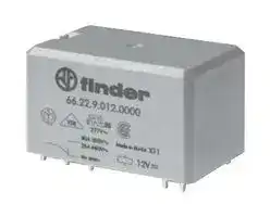
662282300000
Power Relay, DPDT, 230 VAC, 30 A, 66 Series, Through Hole
⚠️ Reference pricing provided. In case of supply shortages, we will connect you with our trusted procurement partners to ensure your project's continuity.
- Manufacturer: FINDER
- Product type: Power Relays
- Contact Configuration:DPDT; Coil Voltage:230VAC; Contact Current:30A; Product Range:66 Series; Relay Mounting:Through Hole; Coil Type:-; Contact Voltage VAC:250V; Relay Terminals:Sold
- SVHC: No SVHC (25-Jun-2025)
- Coil Type: -
- Coil Voltage: 230VAC
- Product Range: 66 Series
- Relay Mounting: Through Hole
- Coil Resistance: 4kohm
- Contact Current: 30A
- Relay Terminals: Solder
- Contact Material: Silver Cadmium Oxide
- Contact Voltage VAC: 250V
- Contact Voltage VDC: -
- Contact Configuration: DPDT
| Delivery and price | |
|---|---|
| Units per pack | 50 |
| Price | 14.95 € |
| Current stock | 10+ |
| Lead time | 30 days |
Datasheet

- OD [

- Power relays 30 A finder

**66 SЕRIES**

Power generators Industrial washing machines Burners, boilers and furnaces Industrial furnaces and ovens Air conditioners Hoists and cranes

**==> picture [37 x 69] intentionally omitted <==**

**----- Start of picture text -----**<br>
Back-up<br>generators<br>Industrial<br>motors<br>**----- End of picture text -----**<br>


FINDER reserves the right to alter characteristics at any time without notice. FINDER assumes no liability for damage to persons or property, caused as a result of the incorrect use or application of its products.

**66 SERIES**

**A**

## **2 Pole Changeover (DPDT) 30 A Power relay**

## **Type 66.22**

- PCB connections & mount

- **Type 66.82**

- Faston 250 connections  and Flange mount

- Reinforced insulation between coil and contacts according to EN 60335-1; 8 mm creepage and clearance distances

- AC coils & DC coils

- Cadmium Free option available

- ATEX compliant (EX nC) option available

- **66.22 66.82** 4 >

- • 30 A rated contacts • 30 A rated contacts • PCB mount - bifurcated • Flange mount terminals • Faston 250 connections

For outline drawing see page 9

|||||68~~.~~5|
|---|---|---|---|---|
||_For ULratings see:_||||
||_“General technical information” page_V||Copper side view||
||**Contact specification**<br>Contact configuration||2 CO (DPDT)|2 CO (DPDT)|
||Rated current/Maximum peak current<br>A||30/50 (NO) - 10/20 (NC)|30/50 (NO) - 10/20 (NC)|
||Rated voltage/<br>Maximum switchingvoltage|V AC|250/440|250/440|
||Rated load AC1|VA|7500 (NO) - 2500 (NC)|7500 (NO) - 2500 (NC)|
||Rated load AC15 (230 V AC)|VA|1200 (NO)|1200 (NO)|
||Single phase motor rating (230 V AC)<br>kW||1.5 (NO)|1.5 (NO)|
||Breaking capacity DC1: 30/110/220 V<br>A||25/0.7/0.3 (NO)|25/0.7/0.3 (NO)|
||Minimum switching load|mW (V/mA)|1000 (10/10)|1000 (10/10)|
||Standard contact material||AgCdO|AgCdO|
||**Coil specification**<br>Nominal voltage (UN)|V AC (50/60 Hz)|6 - 12 - 24 - 110/115 - 120/125 - 230 - 240||
|||V DC|6 - 9 - 12 - 24 - 110 - 125||
||Rated power AC/DC|VA (50 Hz)/W|3.6/1.7|3.6/1.7|
||Operating range|AC|(0.8…1.1)UN|(0.8…1.1)UN|
|||DC|(0.8…1.1)UN|(0.8…1.1)UN|
||Holding voltage|AC/DC|0.8 UN/ 0.5 UN|0.8 UN/ 0.5 UN|
||Must drop-out voltage<br>**Technical data**|AC/DC|0.2 UN/ 0.1 UN|0.2 UN/ 0.1 UN|
||Mechanical life AC/DC|cycles|10 · 106|10 · 106|
||Electrical life at rated load AC1|cycles|100 · 103|100 · 103|
||Operate/release time|ms|8/15|8/15|
||Insulation between coil||||
|II-2019,www.findernet.com|and contacts(1.2/50µs)<br>Dielectric strength<br>between open contacts<br>Ambient temperature range<br>Environmental protection<br>**Approvals**(according to type)|kV<br>V AC<br>°C|6(8 mm)<br>1500<br>–40…+70<br>RT II<br>CE& G FAL ®@|6(8 mm)<br>1500<br>–40…+70<br>RT II<br>®<br> RINA cAXss|


**3**

**66 SERIES**

**A**

## **2 Pole NO (DPST-NO) 30 A Power relay**

## **Type 66.22-x30x**

- PCB mount

**==> picture [50 x 8] intentionally omitted <==**

**----- Start of picture text -----**<br>
66.22-x30x<br>**----- End of picture text -----**<br>


## **66.82-x30x**

## **Type 66.82-x30x**

- Faston 250 connections and Flange mount

- Reinforced insulation between coil and contacts according to EN 60335-1;

- 8 mm creepage and clearance distances

- AC coils & DC coils

- Cadmium Free option available

- ATEX compliant (EX nC) option available

- 30 A rated contacts • 30 A rated contacts • PCB mount - bifurcated • Flange mount terminals • Faston 250 connections

For outline drawing see page 9

|_For ULratings see:_||||||
|---|---|---|---|---|---|
|_“General technical information” page_V||Copper side view||||
|**Contact specification**<br>Contact configuration||2 NO (DPST-NO)||2 NO (DPST-NO)||
|Rated current/Maximum peak current<br>A||30/50|||30/50|
|Rated voltage/<br>Maximum switchingvoltage|V AC|250/440|||250/440|
|Rated load AC1|VA|7500|||7500|
|Rated load AC15 (230 V AC)|VA|1200|||1200|
|Single phase motor rating (230 V AC)<br>kW||1.5|||1.5|
|Breaking capacity DC1: 30/110/220 V<br>A||25/0.7/0.3|||25/0.7/0.3|
|Minimum switching load|mW (V/mA)|1000 (10/10)||1000 (10/10)||
|Standard contact material||AgCdO|||AgCdO|
|**Coil specification**<br>Nominal voltage (UN)|V AC (50/60 Hz)|6 - 12 - 24 - 110/115 - 120/125 - 230 - 240||||
||V DC||6 - 9 - 12 - 24 - 110 - 125|||
|Rated power AC/DC|VA (50 Hz)/W|3.6/1.7|||3.6/1.7|
|Operating range|AC|(0.8…1.1)UN||(0.8…1.1)UN||
||DC|(0.8…1.1)UN||(0.8…1.1)UN||
|Holding voltage|AC/DC|0.8 UN/ 0.5 UN||0.8 UN/ 0.5 UN||
|Must drop-out voltage<br>**Technical data**|AC/DC|0.2 UN/ 0.1 UN||0.2 UN/ 0.1 UN||
|Mechanical life AC/DC|cycles|10 · 106|||10 · 106|
|Electrical life at rated load AC1|cycles|100 · 103|||100 · 103|
|Operate/release time|ms|8/10|||8/10|
|Insulation between coil||||||
|and contacts(1.2/50µs)<br>Dielectric strength<br>between open contacts<br>Ambient temperature range<br>Environmental protection<br>**Approvals**(according to type)|kV<br>V AC<br>°C|6(8 mm)<br>1500<br>–40…+70<br>RT II<br>~~C€~~<br>~~€&G~~|~~FAL®@~~|~~RINA~~|6(8 mm)<br>1500<br>–40…+70<br>RT II<br>®<br>~~cAXss~~|


**4**

**66 SERIES**

**A**

|**2 Pole NO (DPST-NO), ≥ 1.5 mm contact gap**<br>**30 A Power relay**<br>**Type 66.22-x60x**<br>-  PCB mount<br>**Type 66.22-x60xS**<br>-  PCB mount, 5 mm gap between PCB and<br>relay base<br>**Type 66.82-x60x**<br>**-**Faston 250 connections and Flange mount<br>•≥ 1.5 mm contact gap (according to<br>VDE 0126-1-1 for solar inverter applications)<br>•Reinforced insulation between coil and<br>contacts according to EN 60335-1;<br>8 mm creepage and clearance distances<br>•Wash tight version (RT III) available<br>•DC coils<br>•Cadmium Free option available<br>•ATEX compliant (EX nC) option available<br>•<br>For outline drawing see page 9<br>_For ULratings see:_<br>_“General technical information” page_V<br>**Contact specification**<br>Contact configuration<br>a<br>wl|**66.22-x60x**<br>•PCB mount - bifurcated<br>terminals<br>•<br>•<br>a|**66.22-x60x**<br>•PCB mount - bifurcated<br>terminals<br>•<br>•<br>a|**66.22-x60x**<br>•PCB mount - bifurcated<br>terminals<br>•<br>•<br>a|**66.22-x60xS**<br>•PCB mount - bifurcated<br>terminals<br>•5 mm gap between PCB and<br>relaybase<br>•<br>•|**66.82-x60x**<br>Flange mount<br>Faston 250 connections<br>"9<br>||**66.82-x60x**<br>Flange mount<br>Faston 250 connections<br>"9<br>||
|---|---|---|---|---|---|---|
||Copper side view<br>2 NO (DPST-NO)<br>14<br>24<br>2<br>6<br>11<br>21<br>4<br>8<br>0<br>Al<br>A2<br>1<br>5.1<br>31<br>7.5<br>3.5<br>Fe,<br>21 O24<br>| ”<br> <<br>ine<br>8 0 §O1——<br>wl<<br>A~~L~~<br>4~~0~~28~~!~~<br>ite}<br>51~~.~~5|||14.<br>24<br>2<br>6<br>11<br>21<br>4<br>8<br>0<br>Al<br>A2<br>1<br>5.1<br>31<br>75<br>3.5<br>Fe,<br>21 O24<br>i ”<br>wl<<br>1<br>ne<br>80 6o+<br><|2 NO (DPST-NO)<br>14.24<br>2<br>6<br>1<br>21<br>4<br>8<br>0<br>Al<br>A2<br>1<br>33~~.~~5<br>7~~5~~<br>3~~.~~5<br>~~— “| a~~<br>a2<br>~~sl ~~6<br>Z<br>At<br>J<br>All<br>68~~.~~5||
|||||Copper side view<br>2 NO (DPST-NO)<br>A~~L~~<br>4~~0~~28~~!~~<br>te)<br>51~~.~~5|||
|Rated current/Maximum peak current<br>A|30/50|||30/50|30/50||
|Rated voltage/<br>Maximum switchingvoltage<br>V AC|250/440|||250/440|250/440||
|Rated load AC1<br>VA|7500|||7500|7500||
|Rated load AC15 (230 V AC)<br>VA|1200|||1200|1200||
|Single phase motor rating (230 V AC)<br>kW|1.5|||1.5|1.5||
|Breaking capacity DC1: 30/110/220 V<br>A|25/1.2/0.5|||25/1.2/0.5|25/1.2/0.5||
|Minimum switching load<br>mW (V/mA)|1000 (10/10)|||1000 (10/10)|1000 (10/10)||
|Standard contact material<br>**Coil specification**<br>Nominal voltage (UN)<br>V AC (50/60 Hz)<br>V DC|AgCdO<br>AgCdO<br>AgCdO<br>—||||||
||6 - 9 - 12 - 24 - 110 - 125||||||
|Rated power AC/DC<br>VA (50 Hz)/W|—/1.7|||—/1.7|—/1.7||
|Operating range<br>AC<br>DC|—|||—|—||
||(0.8…1.1)UN|||(0.7…1.1)UN|(0.8…1.1)UN||
|Holding voltage<br>AC/DC|—/0.5 UN|||—/0.5 UN|—/0.5 UN||
|Must drop-out voltage<br>AC/DC<br>**Technical data**<br>Mechanical life<br>cycles|—/0.1 UN<br>10 · 106|||—/0.1 UN<br>10 · 106|—/0.1 UN<br>10 · 106||
|Electrical life at rated load AC1<br>cycles|100 · 103|||100 · 103|100 · 103||
|Operate/release time<br>ms|15/4|||15/4|15/4||
|Insulation between coil<br>and contacts(1.2/50µs)<br>kV|6(8 mm)|||6(8 mm)|6(8 mm)||
|Dielectric strength<br>between open contacts<br>V AC|2500|||2500|2500||
|Ambient temperature range<br>°C|–40…+70|||–40…+70|–40…+70||
|Environmental protection|RT II<br>~~FAL ®= cANus~~|||RT II<br>~~cANus~~<br>~~C€~~|RT II<br>~~C€€&FAL®Ads~~||
|**Approvals**(according to type)|&)~~FAL~~|~~FAL ®~~|®<br>~~®= cANus~~<br>~~C€~~||~~C€€&FAL®~~|®<br>~~®Ads~~|


- **66.82-x60x**

- • Flange mount • Faston 250 connections "9 |

**5**

**66 SERIES**

## **Ordering information**

Example:  66 series relay, Faston 250 (6.3x0.8 mm) with top flange mount, 2 CO (DPDT) 30 A contacts, 24 V DC coil.

**A**

**A B C 6 6 . 8 2 . 9 . 0 2 4 . 0 0 0**

## **D**

**0**

## **Series**

## **Type**

2 =  PCB

8 =  Faston 250 (6.3 x 0.8 mm) with top flange mount

**No. of poles**

2 =  2 pole 30 A (versions 0, 1)

2 =  2 pole 25 A (version 3)

## **Coil version**

8 =  AC (50/60 Hz)

9 =  DC

## **Coil voltage**

**A: Contact material**

0 =  Standard AgCdO

1 =  AgNi

## **B: Contact circuit**

0 =  CO (nPDT)

3 =  NO (nPST)

6 =  NO (nPST), ≥ 1.5 mm contact gap

S =  PCB version with 5 mm gap between PCB and relay base (only 66.22)

## **D: Special versions**

0 =  Standard 1 =  Wash tight (RT III) 3 =  ATEX compliant (Ex nC)

## **C: Options**

0 =  None

See coil specifications

## **Selecting features and options: only combinations in the same row are possible.**

Preferred selections for best availability are shown in **bold.**

|**Type**|**Coil version**|**A**|**B**|**C**|**D**|
|---|---|---|---|---|---|
|66.22|AC-DC|**0**- 1|**0**- 3|**0**|0 -**1**|
||DC|**0**- 1|**6**|**0**|0 -**1**|
|66.22….S|DC|**0**- 1|**6**|**0**|0 -**1**- 3|
|66.82|AC-DC|**0**- 1|**0**- 3|**0**|**0**- 1 - 3|
||DC|**0**- 1|**6**|**0**|**0**- 1 - 3|


## **Technical data**

## **Insulation according to EN 61810-1**

|Nominal voltage of supplysystem<br>V AC|Nominal voltage of supplysystem<br>V AC|230/400|230/400|
|---|---|---|---|
|Rated insulation voltage<br>V AC||400||
|Pollution degree||3||
|**Insulation between coil and contact set**||||
|Type of insulation||Reinforced (8 mm)||
|Overvoltage category||III||
|Rated impulse voltage<br>kV (1.2/50µs)||6||
|Dielectric strength<br>V AC||4000||
|**Insulation between adjacent contacts**||||
|Type of insulation||Basic||
|Overvoltage category||III||
|Rated impulse voltage<br>kV (1.2/50µs)||4||
|Dielectric strength<br>V AC||2500||
|**Insulation between open contacts**||**2 CO**|**2 NO, ≥ 1.5 mm (x60x version**)|
|Type of disconnection||Micro-disconnection|Full-disconnection*|
|Overvoltage category||—|II|
|Rated impulse voltage<br>kV (1.2/50µs)||—|2.5|
|Dielectric strength<br>V AC/kV (1.2/50µs)||1500/2|2500/2.5|
|**Insulation between coil terminals**||||
|Rated impulse voltage (surge) differential mode<br>(according to EN 61000-4-5)<br>kV(1.2/50 µs)||4||
|**Other data**||||
|Bounce time: NO/NC<br>ms||7/10||
|Vibration resistance (10…150)Hz: NO/NC<br>g||20/19||
|Shock resistance|g|20||
|Power lost to the environment|without contact current<br>W|2.3||
||with rated current<br>W|5||
|Recommended distance between|relays mounted on PCB<br>mm|≥ 10||


*  Only in applications where over voltage category II is permitted. In applications of over voltage category III: Micro-disconnection.

**6**

**66 SERIES**

**A**

## **Contact specification**

**F 66 -  Electrical life (AC) v contact current**

250 V (normally open contact)

## **F 66 -  Electrical life (AC) v contact current**

440 V (normally open contact)

**==> picture [215 x 102] intentionally omitted <==**

**----- Start of picture text -----**<br>
Resistive load - 250 V AC cos ϕ  = 1<br>Cycles Inductive load - 250 V AC cos ϕ  = 0.4<br>**----- End of picture text -----**<br>


**==> picture [216 x 102] intentionally omitted <==**

**----- Start of picture text -----**<br>
Resistive load - 440 V AC cos ϕ  = 1<br>Cycles Inductive load - 440 V AC cos ϕ  = 0.4<br>**----- End of picture text -----**<br>


**H 66 -  Maximum DC breaking capacity**

**H 66 -  Maximum DC breaking capacity, x60x versions**

**(> 1.5 mm contact gap)**

**==> picture [512 x 144] intentionally omitted <==**

**----- Start of picture text -----**<br>
DC voltage (V) DC voltage (V)<br>DC breaking current (A) DC breaking current (A)<br>**----- End of picture text -----**<br>


- When switching a resistive load (DC1) having voltage and current values under the curve, an electrical life of ≥ 100 · 10[3] can be expected.

- In the case of DC13 loads, the connection of a diode in parallel with the load will permit a similar electrical life as for a DC1 load. Note: the release time for the load will be increased.

## **Coil specifications**

**DC coil data**

|Nominal<br>voltage<br>UN|Coil<br>code|Operating range<br>Umin<br>Umax|Operating range<br>Umin<br>Umax|Resistance<br>R|Rated coil<br>Consumption<br>Iat UN|
|---|---|---|---|---|---|
|V||V|V|Ω|mA|
|6|**9**.006|4.8|6.6|21|283|
|9|**9**.009|7.2|9.9|45|200|
|12|**9**.012|9.6|13.2|85|141|
|24|**9**.024|19.2|26.4|340|70.5|
|110|**9**.110|88|121|7000|15.7|
|125|**9**.125|100|138|9200|13.6|


**R 66 - DC coil operating range v ambient temperature**

**==> picture [237 x 129] intentionally omitted <==**

**==> picture [105 x 8] intentionally omitted <==**

**----- Start of picture text -----**<br>
1 -   Max. permitted coil voltage.<br>**----- End of picture text -----**<br>


**2 -** Min. pick-up voltage with coil at ambient temperature.

## **AC coil data**

|Nominal<br>voltage<br>UN|Coil<br>code|Operating range<br>Umin<br>Umax|Operating range<br>Umin<br>Umax|Resistance<br>R|Rated coil<br>Consumption<br>Iat UN(50 Hz)|
|---|---|---|---|---|---|
|V||V|V|Ω|mA|
|6|**8**.006|4.8|6.6|3|600|
|12|**8**.012|9.6|13.2|11|300|
|24|**8**.024|19.2|26.4|50|150|
|110/115|**8**.110|88|126|930|32.6|
|120/125|**8**.120|96|137|1050|30|
|230|**8**.230|184|253|4000|15.7|
|240|**8**.240|192|264|5500|15|


**R 66 - AC coil operating range v ambient temperature**

**==> picture [236 x 127] intentionally omitted <==**

**1 -** Max. permitted coil voltage.

**2 -** Min. pick-up voltage with coil at ambient temperature.

- **3 -** Min. pick-up voltage with coil at ambient temperature (66.22-x60xS)

**7**

**66 SERIES**

**Features compliant variant ATEX, II 3G Ex nC IIC Gc**

**A**

~~|~~ **MARKING**

Specific marking of explosion protection **II** Component for surface plant (different from mines) **3** Category 3: normal level of protection **G** Explosive atmosphere due to presence of combustible gas vapour or mist ~~ee~~ **Ex nC** Sealed device (type of protection for category 3G) **IIC** Gas group **Gc** Equipment Protection Level **–40 °C ≤ Ta ≤ +70 °C** Ambient temperature ~~ee~~ **EUT 14 ATEX 0150 U** EUT: laboratory which issues the CE type certificate 14: year of issue of certificate 0150: number of CE type certificate U: ATEX component

## **Electrical characteristics**

|Rated current/Maximumpeak current<br>A|25/50 (NO) - 10/20 (NC)|
|---|---|
|Rated voltage/Maximum switchingvoltage<br>V AC|250/400|
|Rated load AC1<br>VA|6250 (NO) - 2500 (NC)|
|Rated load AC15<br>VA|1200 (NO)|
|Capacityfor singlephase motor (230 V AC)<br>kW|1.5 (NO)|
|Breaking capacity DC1: 30/110/220 V<br>A <br>**Characteristics of coil**<br>Rated voltage (UN)<br>V AC (50/60 Hz) <br>V DC|25/0.7/0.3 (NO)<br> 6 - 12 - 24 - 110/115 - 120/125 - 230 - 240|
||6 - 12 - 24 - 110 - 125|
|Rated Power AC/DC<br>VA (50 Hz)/W|3.6/1.7|
|Operating range<br>AC/DC <br>**General characteristics**<br>Ambient temperature<br>°C|(0.8…1.1)UN<br> –40…+70|


## **Special condition for safe use**

The component must be placed inside an enclosure that meets the general requirements for enclosures as per clause 6.3 of EN 60079-15. The connections must be made in compliance with the requirements of clause 7.2.4 or 7.2.5 of EN 60079-15.

## **Wiring**

The cross-section of conductors connected to the terminals, must be at least 4 mm[2] for the Type 66.82.

## **Layout pcb**

The minimum cross-section of the tracks of the printed circuit board must be 0.58 mm[2] , while the width must be at least 4 mm for Types “66.22” and “66.22….S”.

**8**

**66 SERIES**

**A**

## **Outline drawings**

Type 66.22

Type 66.22-0300

Type 66.22-0600

**==> picture [32 x 7] intentionally omitted <==**

**----- Start of picture text -----**<br>
Type 66.82<br>**----- End of picture text -----**<br>


Type 66.82-0300

**==> picture [49 x 7] intentionally omitted <==**

**----- Start of picture text -----**<br>
Type 66.82-0600<br>**----- End of picture text -----**<br>


Type 66.22-0600S

## **Accessories**

## **Top 35 mm rail (EN 60715) mount** for types 66.82.xxxx.0x00

066.07

**==> picture [22 x 5] intentionally omitted <==**

**----- Start of picture text -----**<br>
066.07<br>**----- End of picture text -----**<br>


f **066.07 with relay**

**==> picture [21 x 6] intentionally omitted <==**

**----- Start of picture text -----**<br>
066.07<br>**----- End of picture text -----**<br>


**==> picture [50 x 8] intentionally omitted <==**

**----- Start of picture text -----**<br>
066.07 with relay<br>**----- End of picture text -----**<br>


Please see general technical information

**9**
Updated at June 7, 2026
About Novapart
Novapart is a B2B electronic component broker specialising in stock shortages and cost reduction. We source hard-to-find parts and identify compliant alternatives across a catalogue of 410,000+ components from 500+ manufacturers.
Learn more →Stock Shortage Specialist
When a component is unavailable, discontinued or has an unacceptable lead time, we tap into our network of vetted European and Asian distributors to source what you need — without compromising on quality or traceability.
Request a quote →Compliant Alternatives
We identify pin-to-pin, electrically equivalent substitutes that meet the same certifications (RoHS, AEC-Q100, REACH) as your original specification — validated against datasheets, not just part numbers. Often at a lower cost.
BOM Analysis service →