
Image not available
Illustrative purposes only

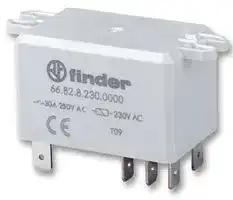
66.82.8.230.0000
General Purpose Relay, 66 Series, Power, DPDT, 230 VAC, 30 A
⚠️ Reference pricing provided. In case of supply shortages, we will connect you with our trusted procurement partners to ensure your project's continuity.
- Manufacturer: FINDER
- Product type: Power Relays
- Contact Configuration:DPDT; Coil Voltage:230VAC; Contact Current:30A; Product Range:66 Series; Relay Mounting:Panel; Coil Type:-; Contact Voltage VAC:250VAC; Relay Terminals:Quick Connect; Conta
- SVHC: No SVHC (25-Jun-2025)
- Coil Type: -
- Coil Voltage: 230VAC
- Product Range: 66 Series
- Relay Mounting: Panel Mount
- Coil Resistance: 4kohm
- Contact Current: 30A
- Relay Terminals: Quick Connect
- Contact Material: Silver Cadmium Oxide
- Contact Voltage VAC: 250VAC
- Contact Voltage VDC: -
- Contact Configuration: DPDT
| Delivery and price | |
|---|---|
| Units per pack | 50 |
| Price | 7.34 € |
| Current stock | 10+ |
| Lead time | 30 days |
Datasheet

66 SЕRIES

## Power relays 30 A

Power generators

Industrial washing machines

Burners, boilers and furnaces

Industrial furnaces and ovens Air conditioners

Hoists and cranes

Back-up generators

Industrial motors

Prices, features, specifications, capabilities, appearance and availability of our products and services are subject to change without notice. FINDER assumes no responsibility for the presence of possible errors or insufficient information in this document. In case of discrepancies between the printed and online versions, the latter prevails.

66 © ~~ti~~ . nder _ SERIES A 7

## **2 Pole Changeover (DPDT) 30 A Power relay**

**==> picture [139 x 7] intentionally omitted <==**

**----- Start of picture text -----**<br>
66.22 66.82<br>**----- End of picture text -----**<br>


**Type 66.22** - PCB connections & mount **Type 66.82**

   - Faston 250 connections  and Flange mount

- Reinforced insulation between coil and contacts according to EN 60335-1; 8 mm creepage and clearance distances

- • AC coils & DC coils • Cadmium Free option available • **ATEX** compliant (Ex ec nC) option available*

- **HazLoc** Class I Div. 2 Group A, B, C, D - T4 - T5 - T6 option available*

- 30 A rated contacts • 30 A rated contacts • PCB mount - bifurcated • Flange mount terminals • Faston 250 connections

* Characteristics page 8, 9

||||51~~.~~5|||||
|---|---|---|---|---|---|---|---|
||_For ULratings see:_<br>_“General technical information” page_V|||||68~~.~~5||
|||||||||
||For outline drawing see page 10||Copper side view|||||
||**Contact specification**<br>Contact configuration||2 CO (DPDT)|||2 CO (DPDT)||
||Rated current/Maximum peak current<br>A||30/50 (NO) - 10/20 (NC)|||30/50 (NO) - 10/20 (NC)||
||Rated voltage/<br>Maximum switchingvoltage|V AC|250/440|||250/440||
||Rated load AC1|VA|7500 (NO) - 2500 (NC)|||7500 (NO) - 2500 (NC)||
||Rated load AC15 (230 V AC)|VA|1200 (NO)|||1200 (NO)||
||Single phase motor rating (230 V AC)|Single phase motor rating (230 V AC)<br>kW|1.5 (NO)|||1.5 (NO)||
||Breaking capacity DC1: 24/110/220 V<br>A||25/0.7/0.3 (NO)|||25/0.7/0.3 (NO)||
||Minimum switching load|mW (V/mA)|1000 (10/10)|||1000 (10/10)||
||Standard contact material||AgCdO|||AgCdO||
||**Coil specification**<br>Nominal voltage (UN)|V AC (50/60 Hz)|6 - 12 - 24 - 110/115 - 120/125 - 230 - 240|||||
|||V DC|6 - 9 - 12 - 24 - 110 - 125|||||
||Rated power AC/DC|VA (50 Hz)/W|3.6/1.7|||3.6/1.7||
||Operating range|AC|(0.8…1.1)UN|||(0.8…1.1)UN||
|||DC|(0.8…1.1)UN|||(0.8…1.1)UN||
||Holding voltage|AC/DC|0.8 UN/ 0.5 UN|||0.8 UN/ 0.5 UN||
||Must drop-out voltage<br>**Technical data**|AC/DC|0.2 UN/ 0.1 UN|||0.2 UN/ 0.1 UN||
||Mechanical life AC/DC|cycles|10 · 106|||10 · 106||
||Electrical life at rated load AC1|cycles|100 · 103|||100 · 103||
||Operate/release time|ms|8/15|||8/15||
||Insulation between coil|||||||
|IV-2023, www.findernet.com|and contacts(1.2/50µs)<br>Dielectric strength<br>between open contacts<br>Ambient temperature range<br>Environmental protection<br>**Approvals**(according to type)|kV<br>V AC<br>°C|6(8 mm)<br>1500<br>–40…+70<br>RT II<br>**c**a €& @ FAL ®<br>CE<br>s<br>@|||6(8 mm)<br>1500<br>–40…+70<br>RT II<br>lus<br>RINA<br>cAkys|@S|


**3**

66 SERIES

A

## **2 Pole NO (DPST-NO) 30 A Power relay**

## **Type 66.22-x30x**

- PCB mount

## **66.22-x30x**

## **66.82-x30x**

## **Type 66.82-x30x**

- Faston 250 connections and Flange mount

- Reinforced insulation between coil and contacts according to EN 60335-1;

- 8 mm creepage and clearance distances

- AC coils & DC coils

- Cadmium Free option available

- **ATEX** compliant (EX ec nC) option available*

   - 30 A rated contacts • 30 A rated contacts

   - PCB mount - bifurcated • Flange mount terminals • Faston 250 connections

- **HazLoc** Class I Div. 2 Group A, B, C, D - T4 - T5 - T6 option available*

- Characteristics page 8, 9

## _For UL ratings see:_

## _“General technical information” page_ V

|For outline drawing see page 10||Copper side view|||
|---|---|---|---|---|
|**Contact specification**<br>Contact configuration||2 NO (DPST-NO)||2 NO (DPST-NO)|
|Rated current/Maximum peak current<br>A||30/50||30/50|
|Rated voltage/<br>Maximum switchingvoltage|V AC|250/440||250/440|
|Rated load AC1|VA|7500||7500|
|Rated load AC15 (230 V AC)|VA|1200||1200|
|Single phase motor rating (230 V AC)|Single phase motor rating (230 V AC)<br>kW|1.5||1.5|
|Breaking capacity DC1: 24/110/220 V<br>A||25/0.7/0.3||25/0.7/0.3|
|Minimum switching load|mW (V/mA)|1000 (10/10)||1000 (10/10)|
|Standard contact material||AgCdO||AgCdO|
|**Coil specification**<br>Nominal voltage (UN)|V AC (50/60 Hz)|6 - 12 - 24 - 110/115 - 120/125 - 230 - 240|||
||V DC|6 - 9 - 12 - 24 - 110 - 125|||
|Rated power AC/DC|VA (50 Hz)/W|3.6/1.7||3.6/1.7|
|Operating range|AC|(0.8…1.1)UN||(0.8…1.1)UN|
||DC|(0.8…1.1)UN||(0.8…1.1)UN|
|Holding voltage|AC/DC|0.8 UN/ 0.5UN||0.8 UN/ 0.5UN|
|Must drop-out voltage<br>**Technical data**|AC/DC|0.2 UN/ 0.1UN||0.2 UN/ 0.1UN|
|Mechanical life AC/DC|cycles|10 · 106||10 · 106|
|Electrical life at rated load AC1|cycles|100 · 103||100 · 103|
|Operate/release time|ms|8/10||8/10|
|Insulation between coil|||||
|and contacts(1.2/50µs)|kV|6(8 mm)||6(8 mm)|
|Dielectric strength|||||
|between open contacts|V AC|1500||1500|
|Ambient temperature range|°C|–40…+70||–40…+70|
|Environmental protection||RT II||RT II|
|**Approvals**(according to type)||C€6&©FAL®|®|RINAAis|


**4**

66 © ~~ti~~ - nder _ SERIES

A

**2 Pole NO (DPST-NO), ≥ 1.5 mm contact gap 30 A Power relay**

## **66.22-x60x**

## **66.22-x60xS**

## **66.82-x60x**

## **Type 66.22-x60x**

- PCB mount

## **Type 66.22-x60xS**

- PCB mount, 5 mm gap between PCB and relay base

## **Type 66.82-x60x**

   - Faston 250 connections and Flange mount

- ≥ 1.5 mm contact gap (according to VDE 0126-1-1 for solar inverter applications)

- Reinforced insulation between coil and contacts according to EN 60335-1; 8 mm creepage and clearance distances

- PCB mount - bifurcated • PCB mount - bifurcated terminals terminals

   - 5 mm gap between PCB and relay base

   - Flange mount

   - Faston 250 connections

- Wash tight version (RT III) available

- DC coils

- Cadmium Free option available

- **ATEX** compliant (EX ec nC) option available*

- **HazLoc** Class I Div. 2 Group A, B, C, D - T4 - T5 - T6 option available*

* Characteristics page 8, 9

_For UL ratings see:_

## _“General technical information” page_ V

||For outline drawing see page 10||Copper side view|Copper side view|||
|---|---|---|---|---|---|---|
||**Contact specification**<br>Contact configuration||2 NO (DPST-NO)|2 NO (DPST-NO)|2 NO (DPST-NO)|2 NO (DPST-NO)|
||Rated current/Maximum peak current<br>A||30/50|30/50||30/50|
||Rated voltage/<br>Maximum switchingvoltage|V AC|250/440|250/440||250/440|
||Rated load AC1|VA|7500|7500||7500|
||Rated load AC15 (230 V AC)|VA|1200|1200||1200|
||Single phase motor rating (230 V AC)|Single phase motor rating (230 V AC)<br>kW|1.5|1.5||1.5|
||Breaking capacity DC1: 24/110/220 V<br>A||25/1.2/0.5|25/1.2/0.5||25/1.2/0.5|
||Minimum switching load|mW (V/mA)|1000 (10/10)|1000 (10/10)||1000 (10/10)|
||Standard contact material||AgCdO|AgCdO||AgCdO|
||**Coil specification**<br>Nominal voltage (UN)|V AC (50/60 Hz)||—|||
|||V DC||6 - 9 - 12 - 24 - 110 - 125|||
||Rated power AC/DC|VA (50 Hz)/W|—/1.7|—/1.7||—/1.7|
||Operating range|AC|—|—||—|
|||DC|(0.8…1.1)UN|(0.7…1.1)UN||(0.8…1.1)UN|
||Holding voltage|AC/DC|—/0.5 UN|—/0.5 UN||—/0.5 UN|
||Must drop-out voltage<br>**Technical data**|AC/DC|—/0.1 UN|—/0.1 UN||—/0.1 UN|
||Mechanical life|cycles|10 · 106|10 · 106||10 · 106|
||Electrical life at rated load AC1|cycles|100 · 103|100 · 103||100 · 103|
||Operate/release time|ms|15/4|15/4||15/4|
||Insulation between coil||||||
|IV-2023, www.findernet.com|and contacts(1.2/50µs)<br>Dielectric strength<br>between open contacts<br>Ambient temperature range<br>Environmental protection<br>**Approvals**(according to type)|kV<br>V AC<br>°C|6(8 mm)<br>2500<br>–40…+70<br>RT II<br>€ FAL ®|6(8 mm)<br>2500<br>–40…+70<br>RT II<br>us<br> cAdys &&|en&)<br>C€es|6(8 mm)<br>2500<br>–40…+70<br>RT II<br>&) FAL@|


**5**

66 SERIES

## **Ordering information**

Example:  66 series relay, Faston 250 (6.3x0.8 mm) with top flange mount, 2 CO (DPDT) 30 A contacts, 24 V DC coil.

A

**A B C D**

**6 6 . 8 2 . 9 . 0 2 4 . 0 0 0 Series A: Contact material**

**0**

S =  PCB version with 5 mm gap between PCB and relay base (only 66.22 and Atex/HazLoc versions)

- 0 =  Standard AgCdO 1 =  AgNi

## **Type**

2 =  PCB

## **B: Contact circuit**

8 =  Faston 250 (6.3 x 0.8 mm) with top flange mount

- 0 =  CO (nPDT) 3 =  NO (nPST)

## **No. of poles**

6 =  NO (nPST), ≥ 1.5 mm contact gap

2 =  2 pole 30 A (versions 0, 1)

## **D: Special versions**

2 =  2 pole 25 A (version 3)

0 =  Standard

## **Coil version**

1 =  Wash tight (RT III)

8 =  AC (50/60 Hz)

3 =  Atex (Ex ec nC) and HazLoc Class I Div. 2 compliant

9 =  DC

## **Coil voltage**

**C: Options**

See coil specifications

0 =  None

## **Selecting features and options: only combinations in the same row are possible.**

Preferred selections for best availability are shown in **bold.**

|**Insulation according to EN 61810-1**|**Insulation according to EN 61810-1**|**Insulation according to EN 61810-1**|**Insulation according to EN 61810-1**|
|---|---|---|---|
|Nominal voltage of supplysystem<br>V AC||230/400||
|Rated insulation voltage<br>V AC||400||
|Pollution degree||3||
|**Insulation between coil and contact set**||||
|Type of insulation||Reinforced (8 mm)||
|Overvoltage category||III||
|Rated impulse voltage<br>kV (1.2/50µs)||6||
|Dielectric strength<br>V AC||4000||
|**Insulation between adjacent contacts**||||
|Type of insulation||Basic||
|Overvoltage category||III||
|Rated impulse voltage<br>kV (1.2/50µs)||4||
|Dielectric strength<br>V AC||2500||
|**Insulation between open contacts**||**2 CO**|**2 NO, ≥ 1.5 mm (x60x version**)|
|Type of disconnection||Micro-disconnection|Full-disconnection*|
|Overvoltage category||—|II|
|Rated impulse voltage<br>kV (1.2/50µs)||—|2.5|
|Dielectric strength<br>V AC/kV (1.2/50µs)||1500/2|2500/2.5|
|**Insulation between coil terminals**||||
|Rated impulse voltage (surge) differential mode<br>(according to EN 61000-4-5)<br>kV (1.2/50 µs)||4||
|**Other data**||||
|Bounce time: NO/NC<br>ms||7/10||
|Vibration resistance (10…150)Hz: NO/NC<br>g||20/19||
|Shock resistance|g|20||
|Power lost to the environment|without contact current<br>W|2.3||
||with rated current<br>W|5||
|Recommended distance between|relays mounted on PCB<br>mm|≥ 10||


*  Only in applications where over voltage category II is permitted. In applications of over voltage category III: Micro-disconnection.

**6**

66 SERIES

A

## **Contact specification**

**F 66 -  Electrical life (AC) v contact current**

250 V (normally open contact)

## **F 66 -  Electrical life (AC) v contact current**

440 V (normally open contact)

**==> picture [215 x 102] intentionally omitted <==**

**----- Start of picture text -----**<br>
Resistive load - 250 V AC cosφ = 1<br>Inductive load - 250 V AC cosφ = 0.4<br>Cycles<br>**----- End of picture text -----**<br>


**==> picture [216 x 102] intentionally omitted <==**

**----- Start of picture text -----**<br>
Resistive load - 440 V AC cosφ = 1<br>Cycles Inductive load - 440 V AC cosφ = 0.4<br>**----- End of picture text -----**<br>


**H 66 -  Maximum DC breaking capacity**

**H 66 -  Maximum DC breaking capacity, x60x versions**

**(> 1.5 mm contact gap)**

**==> picture [512 x 144] intentionally omitted <==**

**----- Start of picture text -----**<br>
DC voltage (V) DC voltage (V)<br>DC breaking current (A) DC breaking current (A)<br>**----- End of picture text -----**<br>


- When switching a resistive load (DC1) having voltage and current values under the curve, an electrical life of ≥ 100 · 10[3] can be expected.

- In the case of DC13 loads, the connection of a diode in parallel with the load will permit a similar electrical life as for a DC1 load. Note: the release time for the load will be increased.

## **Coil specifications**

**DC coil data**

|Nominal<br>voltage<br>UN|Coil<br>code|Operating range<br>Umin<br>Umax|Operating range<br>Umin<br>Umax|Resistance<br>R|Rated coil<br>Consumption<br>Iat UN|
|---|---|---|---|---|---|
|V||V|V|Ω|mA|
|6|**9**.006|4.8|6.6|21|283|
|9|**9**.009|7.2|9.9|45|200|
|12|**9**.012|9.6|13.2|85|141|
|24|**9**.024|19.2|26.4|340|70.5|
|110|**9**.110|88|121|7000|15.7|
|125|**9**.125|100|138|9200|13.6|


**R 66 - DC coil operating range v ambient temperature**

## **AC coil data**

|Nominal<br>voltage<br>UN|Coil<br>code|Operating range<br>Umin<br>Umax|Operating range<br>Umin<br>Umax|Resistance<br>R|Rated coil<br>Consumption<br>Iat UN(50 Hz)|
|---|---|---|---|---|---|
|V||V|V|Ω|mA|
|6|**8**.006|4.8|6.6|3|600|
|12|**8**.012|9.6|13.2|11|300|
|24|**8**.024|19.2|26.4|50|150|
|110/115|**8**.110|88|126|930|32.6|
|120/125|**8**.120|96|137|1050|30|
|230|**8**.230|184|253|4000|15.7|
|240|**8**.240|192|264|5500|15|


**R 66 - AC coil operating range v ambient temperature**

**1 -** Max. permitted coil voltage. **2 -** Min. pick-up voltage with coil at ambient temperature. **3 -** Min. pick-up voltage with coil at ambient temperature (66.22-x60xS)

- **3 -** Min. pick-up voltage with coil at ambient temperature (66.22-x60xS)

**==> picture [236 x 127] intentionally omitted <==**

**1 -** Max. permitted coil voltage.

**2 -** Min. pick-up voltage with coil at ambient temperature.

**7**

66 SERIES

## **ATEX - Electrical characteristics**

|**Contact specification ATEX**<br>Rated current/Maximumpeak current<br>A|**66.82**<br> 30/50 (NO) - 10/20 (NC)|**66.22…S**<br>25/50 (NO) - 10/20 (NC)|
|---|---|---|
|Rated voltage/Maximum switchingvoltage<br>V AC|250/440||
|Rated load AC1<br>VA|7500 (NO) - 2500 (NC)|6250 (NO) - 2500 (NC)|
|Rated load AC15<br>VA|1200 (NO)||
|Capacityfor singlephase motor (230 V AC)<br>kW|1.5 (NO)||
|Breaking capacity DC1: 30/110/220 V<br>A<br>**Characteristics of coil**<br>Rated voltage (UN)<br>V AC (50/60 Hz) <br>V DC|25/0.7/0.3 (NO)<br> 6 - 12 - 24 - 110/115 - 120/125 - 230 - 240||
||6 - 12 - 24 - 110 - 125||
|Rated Power AC/DC<br>VA (50 Hz)/W|3.6/1.7||
|Operating range<br>AC/DC <br>**General characteristics**<br>Ambient temperature<br>°C|(0.8…1.1)UN<br> –40…+70||


## **Special condition for safe use**

The component must be placed inside an enclosure that ensures a degree of protection IP54 (or greater) according to standard EN 60529 and EN 60079-0 and that complies with the requirements of type of protection "Ex e" and EPL Gc (or better).

## **Wiring**

The cross-section of conductors connected to the terminals, must be at least 4 mm[2] for the Type 66.82.

The connections must be made in compliance with the requirements of clause 4.2 of EN IEC 60079-7:2015+A1:2018.

## **Layout pcb**

The minimum cross-section of the tracks of the printed circuit board must be 0.58 mm[2] , while the width must be at least 4.01 mm for Type 66.22….S.

## **Markings - AT** ~~**E**~~ **X** ~~**v**~~ **ersions - ATEX, II 3G Ex ec nC IIC Gc**

## **MARKING**

|Specific markingof explosionprotection|Specific markingof explosionprotection|
|---|---|
|**II**||
|Component for surfaceplant(different from mines)||
|**3**<br>Category3: normal level ofprotection<br>**G**||
||Explosive atmosphere due topresence of combustiblegas vapour or mist|
||**Ex ec**|
||Increased safety (type ofprotection for category3G)|
|**GAS**|**Ex nC**<br>Sealed device(type ofprotection for category3G)|
|**IIC**<br>Gasgroup<br>**Gc**<br>Equipment Protection Level<br>**–40 °C ≤ Ta ≤ +70 °C**<br>Ambient temperature<br>**EPTI 17 ATEX 0299 U**<br>EPTI: laboratory which issues the voluntary type certificate<br>17: year of issue of certificate<br>0299: number of CE type certificate<br>U: Ex component<br>Xyy: production batch identification (X year, yy week)<br>~~Oc~~||


**8**

66 SERIES

A

## **Markings -  Hazardous Location Class I Div. 2 Goups A, B, C, D - T4 - T5 - T6 and other data**

|**HazLoc Class I Div. 2 Group A, B, C, D - T4 - T5 - T6**|**HazLoc Class I Div. 2 Group A, B, C, D - T4 - T5 - T6**|**HazLoc Class I Div. 2 Group A, B, C, D - T4 - T5 - T6**|**Meaning**|**Meaning**|**Meaning**|
|---|---|---|---|---|---|
|Class I|||Areas in which flammable gases and vapours may be present|||
|Div. 2|||Low probability to find ignitable concentration of hazards because are<br>typically present in containers or closed systems from which can escape<br>through their accidental rupture or breakdown|||
|Group A, B, C, D|||Kind of combustible, flammable gases and vapours can be in the atmosphere.|||
|||Permissible Surface temperature||||
|T4||135 °C||275 °F||
|T5||100 °C||212 °F||
|T6||85 °C||185 °F||
|||||||
|**Model**||**T4**||||
||Type of load|Voltage|Current/Power|Temperature °C|Note|
|66.22|DC General Use<br>Res Heating|30 V|25 A|–40…+70|only 66.xx.9.x6x3|
|66.22/66.82|AC Motor Starting,<br>Discharge Lamps<br>Break All lines|240 V|2 Hp|–40…+70|12FLA/69 LRA|
|||120 V|1 Hp|—|16FLA/96 LRA|
|||120 V|1/2 Hp|—|9.8FLA/58.8 LRA|
|||||||
|**Model**||**T5**||||
|66.22.x.xxx.xxx3 x|Type of load|Voltage|Current/Power|Temperature °C|Note|
||DC General Use<br>Res Heating|30 V|30 A|–40…+60|only 66.xx.9.x6x3|
||AC Motor Starting,<br>Discharge Lamps<br>Break All lines|240 V|2 Hp|–40…+60|12FLA/69 LRA|
|||120 V|1 Hp||16FLA/96 LRA|
|||120 V|1/2 Hp||9.8FLA/58.8 LRA|
|||**T6**||||
||Type of load|Voltage|Current|Temperature °C|—|
||AC General Use|277 V|10 A(NC)|–40…+70|—|
|||||||
|**Model**||**T5**||||
|66.82.x.xxx.xxx3 x|Type of load|Voltage|Current/Power|Temperature °C|Note|
||AC General Use|277 V|25(NO)|–40…+40|—|
||DC General Use|30 V|30 A|–40…+60|only66.xx.9.x6x3|
||AC Motor Starting,<br>Discharge Lamps<br>Break All lines|240 V|2 Hp|–40…+60|12FLA/69 LRA|
|||120 V|1 Hp||16FLA/96 LRA|
|||120 V|1/2 Hp||9.8FLA/58.8 LRA|
|||**T6**||||
||Type of load|Voltage|Current|Temperature °C|—|
||AC General Use|277 V|10 A(NC)|–40…+70|—|


## **HazLoc - Electrical characteristics**

**==> picture [521 x 215] intentionally omitted <==**

**----- Start of picture text -----**<br>
Contact specification HazLoc HazLoc Class I Div. 2 T4 @ 60°C HazLoc Class I Div. 2 T4 @ 70°C<br>Rated current/Maximum peak current  A 30/50 (NO) - 10/20 (NC) 25/50 (NO) - 10/20 (NC)<br>Rated voltage/Maximum switching voltage  V AC 250/400 250/400<br>Rated load AC1  VA 7500 (NO) - 2500 (NC) 6250 (NO) - 2500 (NC)<br>Rated load AC15  VA 1200 (NO) 1200 (NO)<br>Capacity for single phase motor (230 V AC)  kW 1.5 (NO) 1.5 (NO)<br>Breaking capacity DC1: 30/110/220 V  A 25/0.7/0.3 (NO) 25/0.7/0.3 (NO)<br>Characteristics of coil<br>Rated voltage (UN) V AC (50/60 Hz) 6 - 12 - 24 - 110/115 - 120/125 - 230 - 240<br>V DC 6 - 12 - 24 - 110 - 125<br>Rated Power AC/DC  VA (50 Hz)/W 3.6/1.7<br>Operating range   AC/DC (0.8…1.1)UN<br>General characteristics<br>Ambient temperature  °C –40…+70<br>IV-2023, www.findernet.com<br>**----- End of picture text -----**<br>


**9**

66 SERIES

## **Outline drawings**

**==> picture [32 x 7] intentionally omitted <==**

**----- Start of picture text -----**<br>
Type 66.22<br>**----- End of picture text -----**<br>


**==> picture [32 x 7] intentionally omitted <==**

**----- Start of picture text -----**<br>
Type 66.82<br>**----- End of picture text -----**<br>


**==> picture [8 x 10] intentionally omitted <==**

**----- Start of picture text -----**<br>
A<br>**----- End of picture text -----**<br>


**==> picture [48 x 7] intentionally omitted <==**

**----- Start of picture text -----**<br>
Type 66.22-0300<br>**----- End of picture text -----**<br>


**==> picture [48 x 8] intentionally omitted <==**

**----- Start of picture text -----**<br>
Type 66.22-0600<br>**----- End of picture text -----**<br>


**==> picture [49 x 7] intentionally omitted <==**

**----- Start of picture text -----**<br>
Type 66.82-0300<br>**----- End of picture text -----**<br>


Type 66.82-0600

Type 66.22-0600S

## **Accessories**

**==> picture [22 x 5] intentionally omitted <==**

**----- Start of picture text -----**<br>
066.07<br>**----- End of picture text -----**<br>


**==> picture [54 x 7] intentionally omitted <==**

**----- Start of picture text -----**<br>
066.07 with relay<br>**----- End of picture text -----**<br>


**==> picture [335 x 151] intentionally omitted <==**

**----- Start of picture text -----**<br>
Top 35 mm rail (EN 60715) mount  for types 66.82.xxxx.0x00 066.07<br>6 . 3<br>36.1 ri<br>| OD<br>T o ri [ealre *<br>o| ¥ a r js x<br>2 3 re) 88 »|/8 8<br>068.07 =I= i<br>— is— _ a ata a ja e |<br>11.4 a 36 . 2 %<br>44<br>066.07 066.07 with relay<br>**----- End of picture text -----**<br>


Please see general technical information

**10**
Updated at June 7, 2026
About Novapart
Novapart is a B2B electronic component broker specialising in stock shortages and cost reduction. We source hard-to-find parts and identify compliant alternatives across a catalogue of 410,000+ components from 500+ manufacturers.
Learn more →Stock Shortage Specialist
When a component is unavailable, discontinued or has an unacceptable lead time, we tap into our network of vetted European and Asian distributors to source what you need — without compromising on quality or traceability.
Request a quote →Compliant Alternatives
We identify pin-to-pin, electrically equivalent substitutes that meet the same certifications (RoHS, AEC-Q100, REACH) as your original specification — validated against datasheets, not just part numbers. Often at a lower cost.
BOM Analysis service →