
Image not available
Illustrative purposes only

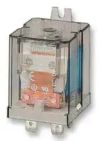
65.31.9.012.0300
Power Relay, SPST-NO, 12 VDC, 30 A, 65 Series, Panel Mount
⚠️ Reference pricing provided. In case of supply shortages, we will connect you with our trusted procurement partners to ensure your project's continuity.
- Manufacturer: FINDER
- Product type: Power Relays
- Contact Configuration:SPST-NO; Coil Voltage:12VDC; Contact Current:30A; Product Range:65 Series; Relay Mounting:Panel; Coil Type:-; Contact Voltage VAC:250VAC; Relay Terminals:Quick Connect;
- SVHC: No SVHC (25-Jun-2025)
- Coil Type: -
- Coil Voltage: 12VDC
- Product Range: 65 Series
- Relay Mounting: Panel Mount
- Coil Resistance: 110ohm
- Contact Current: 30A
- Relay Terminals: Quick Connect
- Contact Material: Silver Cadmium Oxide
- Contact Voltage VAC: 250V
- Contact Voltage VDC: -
- Contact Configuration: SPST-NO
| Delivery and price | |
|---|---|
| Units per pack | 50 |
| Price | 10.98 € |
| Current stock | 10+ |
| Lead time | 30 days |
Datasheet

**65 SERIES**

**A**

**20 A Power relays 1 NO + 1 NC (SPST-NO + SPST-NC) 65.31  Flange mount Faston 250 connections 65.61  PCB mount**

**==> picture [357 x 228] intentionally omitted <==**

**----- Start of picture text -----**<br>
20 A Power relays 65.31 65.61<br>1 NO + 1 NC (SPST-NO + SPST-NC)<br>65.31  Flange mount<br>Faston 250 connections a | ji in<br>65.61  PCB mount<br>• AC coils & DC coils<br>• Cadmium Free option available<br>32 . 2 36 . 6 • 20 A rated contacts • 20 A rated contacts<br>e e e s • Flange mount/Faston 250  • PCB mount -<br>(6.3 x 0.8 mm) connection bifurcated terminals<br>;<br>g 21—o-o— 22 21—o-o—22<br>ll—o o— 14 1l—oo— 14<br>46 vu UY vw TT Al A2 Al A2<br>e tn 14 0.8 + 32.2 36.5<br>65.61 3.6<br>**----- End of picture text -----**<br>


- With the AgSnO2 material the maximum peak current is 120 A - 5 ms on NO contact.

- _For UL ratings see:_

**==> picture [58 x 9] intentionally omitted <==**

**----- Start of picture text -----**<br>
Copper side view<br>**----- End of picture text -----**<br>


|_For UL ratingsor UL ratings UL ratingsratings see::_|_For UL ratingsor UL ratings UL ratingsratings see::_||||Copper side view|
|---|---|---|---|---|---|
|_“General technical information” page_V||||||
|**Contact specification**<br>Contact configuration||1NO + 1NC (SPST-NO+SPST-NC)|||1NO + 1NC (SPST-NO+SPST-NC)|
|Rated current/Maximum peak current<br>A||20/40*|||20/40*|
|Rated voltage/<br>Maximum switchingvoltage|V AC|250/400|||250/400|
|Rated load AC1|VA|5000|||5000|
|Rated load AC15 (230 V AC)|VA|1000|||1000|
|Single phase motor rating (230 V AC)|Single phase motor rating (230 V AC)<br>kW|1.1|||1.1|
|Breaking capacity DC1: 30/110/220 V<br>A||20/0.8/0.5|||20/0.8/0.5|
|Minimum switching load|mW (V/mA)|1000 (10/10)|||1000 (10/10)|
|Standard contact material<br>**Coil specification**||AgCdO|||AgCdO|
|Nominal voltage (UN)|V AC (50/60 Hz)|6 - 12 - 24 - 48 - 60 - 110 - 120 - 230 - 240 - 400|||6 - 12 - 24 - 48 - 60 - 110 - 120 - 230 - 240 - 400|
||V DC|6 - 12 - 24 - 48 - 60 - 110 - 125 - 220|||6 - 12 - 24 - 48 - 60 - 110 - 125 - 220|
|Rated power AC/DC|VA (50 Hz)/W|2.2/1.3|||2.2/1.3|
|Operating range|AC|(0.8…1.1)UN|||(0.8…1.1)UN|
||DC|(0.85…1.1)UN|||(0.85…1.1)UN|
|Holding voltage|AC/DC|0.8 UN/ 0.6 UN|||0.8 UN/ 0.6 UN|
|Must drop-out voltage<br>**Technical data**|AC/DC|0.2 UN/ 0.1 UN|||0.2 UN/ 0.1 UN|
|Mechanical life AC/DC|cycles|10 · 106/ 30 · 106|||10 · 106/ 30 · 106|
|Electrical life at rated load AC1|cycles|80 · 103|||80 · 103|
|Operate/release time|ms|10/12|||10/12|
|Insulation between coil||||||
|and contacts(1.2/50μs)|kV|4|||4|
|Dielectric strength<br>between open contacts<br>Ambient temperature range<br>Environmental protection<br>**Approvals**(according to type)|V AC<br>°C|1500<br>–40…+75<br>RT I<br>ce@|HALS&S|S&S|1500<br>–40…+75<br>RT I<br>®<br>®@Ais|


**1**

**65 SERIES**

## **30 A Power relays**

**==> picture [51 x 7] intentionally omitted <==**

**----- Start of picture text -----**<br>
65.31-0300<br>**----- End of picture text -----**<br>


**==> picture [51 x 7] intentionally omitted <==**

**----- Start of picture text -----**<br>
65.61-0300<br>**----- End of picture text -----**<br>


## **1 NO (SPST-NO)**

## **65.31-0300  Flange mount**

**A**

## **Faston 250 connections**

## **65.61-0300  PCB mount**

- ≥ 3 mm contact gap

- AC coils & DC coils

- Cadmium Free option available

- 30 A rated contacts

   - 30 A rated contacts

- Flange mount/Faston 250 • PCB mount - (6.3 x 0.8 mm) connection bifurcated terminals

**==> picture [38 x 6] intentionally omitted <==**

**----- Start of picture text -----**<br>
65.61-0300<br>**----- End of picture text -----**<br>


- Distance between contacts ≥ 3 mm (EN 60335-1).

- **  With the AgSnO2 material the maximum peak current is 120 A - 5 ms on NO contact.

|current is 120 A - 5 ms on NO contact.|current is 120 A - 5 ms on NO contact.||||Copper side view|
|---|---|---|---|---|---|
|_For ULratings see:_||||||
|_“General technical information” page_V||||||
|**Contact specification**<br>Contact configuration||1 NO (SPST-NO), ≥ 3 mm*|||1 NO (SPST-NO), ≥ 3 mm*|
|Rated current/Maximum peak current<br>A||30/50**|||30/50**|
|Rated voltage/<br>Maximum switchingvoltage|V AC|250/400|||250/400|
|Rated load AC1|VA|7500|||7500|
|Rated load AC15 (230 V AC)|VA|1250|||1250|
|Single phase motor rating (230 V AC)<br>kW||1.5|||1.5|
|Breaking capacity DC1: 30/110/220 V<br>A||30/1.1/0.7|||30/1.1/0.7|
|Minimum switching load|mW (V/mA)|1000 (10/10)|||1000 (10/10)|
|Standard contact material<br>**Coil specification**||AgCdO|||AgCdO|
|Nominal voltage (UN)|V AC (50/60 Hz)|6 - 12 - 24 - 48 - 60 - 110 - 120 - 230 - 240 - 400||||
||V DC|6 - 12 - 24 - 48 - 60 - 110 -125 - 220||||
|Rated power AC/DC|VA (50 Hz)/W|2.2/1.3|||2.2/1.3|
|Operating range|AC|(0.8…1.1)UN|||(0.8…1.1)UN|
||DC|(0.85…1.1)UN|||(0.85…1.1)UN|
|Holding voltage|AC/DC|0.8 UN/ 0.6 UN|||0.8 UN/ 0.6 UN|
|Must drop-out voltage<br>**Technical data**|AC/DC|0.2 UN/ 0.1 UN|||0.2 UN/ 0.1 UN|
|Mechanical life AC/DC|cycles|10 · 106/ 30 · 106|||10 · 106/ 30 · 106|
|Electrical life at rated load AC1|cycles|50 · 103|||50 · 103|
|Operate/release time|ms|15/4|||15/4|
|Insulation between coil||||||
|and contacts(1.2/50μs)|kV|4|||4|
|Dielectric strength||||||
|between open contacts|V AC|2500|||2500|
|Ambient temperature range|°C|–40…+75|||–40…+75|
|Environmental protection||RT I|||RT I|
|**Approvals**(according to type)||Ce@|FHL&|&|®<br>@Nis|


**2**

**65 SERIES**

**A**

## **Ordering information**

Example:  65 series power relay, PCB with bifurcated terminals, 1 NO + 1 NC (SPST-NO + SPST-NC) contact, 12 V DC coil.

**A B C D 0 0 0 0**

## **6 5 . 6 1 . 9 . 0 1 2 . 0 A: Contact material**

## **D: Special versions**

## **Series**

0 =  Standard AgCdO

0 = Standard

- 9 =  Type 65.31 without rear flange mount

4 =  AgSnO2

## **Type**

3 =  Faston 250 (6.3 x 0.8 mm) with rear flange mount

**B: Contact circuit**

6 =  PCB with bifurcated terminals

**C: Options**

0 =  1 NO + 1 NC (SPST-NO + SPST-NC)

- 0 =  None

## **No. of poles**

3 =  NO (≥ 3 mm contact gap)

1 =  1 NO + 1 NC (SPST-NO + SPST-NC)

## **Coil version**

8 =  AC (50/60 Hz) 9 =  DC

## **Coil voltage**

See coil specifications

**Selecting features and options: only combinations in the same row are possible.** Preferred selections for best availability are shown in **bold** .

|**Type**|**Coil version**|**A**|**B**|**C**|**D**|
|---|---|---|---|---|---|
|65.31|AC-DC|**0**- 4|**0**- 3|**0**|**0**- 9|
|65.61|AC-DC|**0**- 4|**0**- 3|**0**|**0**|


## **Technical data**

## **Insulation according to EN 61810-1**

||**Insulation according to EN 61810-1**|**Insulation according to EN 61810-1**|||||
|---|---|---|---|---|---|---|
|-2014, www.findernet.com|||**1 NO + 1 NC**||**1 NO**||
||Nominal voltage supply system<br>V AC||230/400||230/400||
||Rated insulation voltage<br>V AC||250|400|250|400|
||Pollution degree||3|2|3|2|
||**Insulation between coil and contact set**||||||
||Type of insulation||Basic||Basic||
||Overvoltage category||III||III||
||Rated impulse voltage<br>kV (1.2/50 μs)||4||4||
||Dielectric strength<br>V AC||2500||2500||
||**Insulation between open contacts**||||||
||Type of disconnection||Micro-disconnection||Full-disconnection||
||Overvoltage category||—||III||
||Rated impulse voltage<br>kV (1.2/50 μs)||—||4||
||Dielectric strength<br>V AC/kV (1.2/50 μs)||1500/2||2500/4||
||**Conducted disturbance immunity**||||||
||Burst (5…50)ns, 5 kHz, on A1 - A2||EN 61000-4-4||level 4 (4 kV)||
||Surge (1.2/50 μs) on A1 - A2 (differential mode)||EN 61000-4-5||level 4 (4 kV)||
||**Other data**||||||
||Bounce time: NO/NC<br>ms||5/6<br>(1 normallyopen + 1 normallyclosed)||7/—<br>(normallyopen)||
||Vibration resistance (10…150)Hz: NO/NC<br>g||20/13||||
||Shock resistance|g|20||||
||Power lost to the environment|without contact current<br>W|1.3||||
|||with rated current<br>W|2.1 (65.31, 65.61)||3.1 (65.31/.61.0300)||
||Recommended distance between relays mounted on PCB<br>mm||≥ 5||||


**3**

**65 SERIES**

## **Contact specification**

**F 65 - Electrical life (AC) v contact current H 65 - Maximum DC1 breaking capacity**

**A**

**==> picture [229 x 108] intentionally omitted <==**

**----- Start of picture text -----**<br>
Resistive load - cosφ = 1<br>Inductive load - cosφ = 0.4<br>limit for 1NO+1NC types<br>Cycles<br>**----- End of picture text -----**<br>


**==> picture [218 x 128] intentionally omitted <==**

**----- Start of picture text -----**<br>
1 normally open type<br>1 normally open + 1 normally closed type<br>DC voltage (V)<br>DC breaking current (A)<br>**----- End of picture text -----**<br>


- When switching a resistive load (DC1) having voltage and current values under the curve, an electrical life of ≥ 80 · 10[3] can be expected.

- In the case of DC13 loads, the connection of a diode in parallel with the load will permit a similar electrical life as for a DC1 load. Note: the release time for the load will be increased.

## **Coil specifications**

## **DC coil data**

## **AC coil data**

**==> picture [512 x 54] intentionally omitted <==**

**----- Start of picture text -----**<br>
Nominal  Coil code Operating range Resistance Rated coil  Nominal  Coil code Operating range Resistance Rated coil<br>voltage consumption voltage consumption<br>UN Umin Umax R I at UN UN Umin Umax R I at UN (50 Hz)<br>V V V Ω mA V V V Ω mA<br>**----- End of picture text -----**<br>


|6|**9**.006|5.1|6.6|28|214||6|**8**.006|4.8|6.6|4.6|367|
|---|---|---|---|---|---|---|---|---|---|---|---|---|
|12|**9**.012|10.2|13.2|110|109||12|**8**.012|9.6|13.2|19|183|
|24|**9**.024|20.4|26.4|445|54||24|**8**.024|19.2|26.4|74|90|
|48|**9**.048|40.8|52.8|1770|27.1||48|**8**.048|38.4|52.8|290|47|
|60|**9**.060|51|66|2760|21.7||60|**8**.060|48|66|450|37|
|110|**9**.110|93.5|121|9420|11.7||110|**8**.110|88|121|1600|20|
|125|**9**.125|106|138|12000|10.4||120|**8**.120|96|132|1940|18.6|
|220|**9**.220|187|242|37300|5.8||230|**8**.230|184|253|7250|10.5|
||||||||240|**8**.240|192|264|8500|9.2|
||||||||400|**8**.400|320|440|19800|6|


**R 65 - DC coil operating range v ambient temperature**

**==> picture [240 x 128] intentionally omitted <==**

**==> picture [104 x 8] intentionally omitted <==**

**----- Start of picture text -----**<br>
1 -   Max. permitted coil voltage.<br>**----- End of picture text -----**<br>


**==> picture [193 x 8] intentionally omitted <==**

**----- Start of picture text -----**<br>
2 -   Min. pick-up voltage with coil at ambient temperature.<br>**----- End of picture text -----**<br>


## **R 65 - AC coil operating range v ambient temperature**

**==> picture [239 x 128] intentionally omitted <==**

**==> picture [104 x 8] intentionally omitted <==**

**----- Start of picture text -----**<br>
1 -   Max. permitted coil voltage.<br>**----- End of picture text -----**<br>


**==> picture [192 x 8] intentionally omitted <==**

**----- Start of picture text -----**<br>
2 -   Min. pick-up voltage with coil at ambient temperature.<br>**----- End of picture text -----**<br>


**4**

**65**

**SERIES**

**A**

## **Accessories**

**==> picture [435 x 144] intentionally omitted <==**

**----- Start of picture text -----**<br>
Top flange mount  for types 65.31.xxxx.xxx9 065.05<br>34.5 44.4<br>a 28 3 42.7 17 3.6 42.2<br>065.05 o o n<br>065.05 065.05 with relay<br>065.05 with relay<br>**----- End of picture text -----**<br>


**==> picture [434 x 331] intentionally omitted <==**

**----- Start of picture text -----**<br>
Top 35 mm rail (EN 60715) mount  for types 65.31.xxxx.xxx9 065.07<br>30<br>6s ro<br>- 065.07 o Wkodd .<br>iS ; jor 3 } WY,<br>{ 15 41<br>065.07 065.07 with relay<br>065.07 with relay<br>Rear 35 mm rail (EN 60715) mount  for types 65.31.xxxx.xxx9 065.08<br>a 29.4 “ yk 35.4 4<br>065.08<br>| 2 aq=o ° ° e s, ; SS <n<br>O ° ae oh .<br>065.08 == |<br>: 53.6<br>065.08 with relay<br>065.08<br>065.08 with relay<br>**----- End of picture text -----**<br>


**5**
Updated at June 7, 2026
About Novapart
Novapart is a B2B electronic component broker specialising in stock shortages and cost reduction. We source hard-to-find parts and identify compliant alternatives across a catalogue of 410,000+ components from 500+ manufacturers.
Learn more →Stock Shortage Specialist
When a component is unavailable, discontinued or has an unacceptable lead time, we tap into our network of vetted European and Asian distributors to source what you need — without compromising on quality or traceability.
Request a quote →Compliant Alternatives
We identify pin-to-pin, electrically equivalent substitutes that meet the same certifications (RoHS, AEC-Q100, REACH) as your original specification — validated against datasheets, not just part numbers. Often at a lower cost.
BOM Analysis service →