
Image not available
Illustrative purposes only

64082000
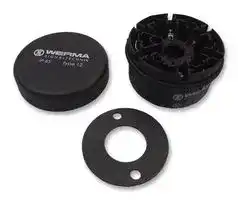
Signal Indicator Accessory, KombiSIGN 71, Terminal, Black, Screwable
⚠️ Reference pricing provided. In case of supply shortages, we will connect you with our trusted procurement partners to ensure your project's continuity.
- Manufacturer: WERMA
- Product type: Signal Indicator Accessories
- Accessory Type:Terminal, Black, Screwable; For Use With:KombiSIGN 71; Product Range:-; SVHC:No SVHC (15-Jan-2019); IP / NEMA Rating:IP65
- SVHC: Lead (21-Jan-2025)
- For Use With: KombiSIGN 71
- Product Range: -
- Accessory Type: Terminal, Black, Screwable
| Delivery and price | |
|---|---|
| Units per pack | 10 |
| Price | 18.9 € |
| Current stock | 10+ |
| Lead time | 30 days |
Datasheet

S I G N A L T E C H N I K Gq) WERMA

Kombi _SIGN_ 50, 70 and 71 Signals for combining – at the twist of a hand

KombiSIGN 50

KombiSIGN 71

KombiSIGN 70

## Accessories for Si nal Tower Kombi _SIGN_ 71 g

## ORDER SPECIFICATIONS:

Bulb BA 15 d, Total length max. 42 mm 12 V, 5 Watt 955 840 34 24 V, 5 Watt 955 840 35 115 V, 5 Watt 955 840 57 230 V, 5 Watt 955 840 38

LED-Bulb BA 15d, Total length max. 42 mm Voltage 24 V ≅ 115 V ∼ 230 V ∼ Current consumption < 45 mA < 15 mA < 15 mA red 956 100 75 956 100 67 956 100 68 green 956 200 75 956 200 67 956 200 68 ~~@~~ yellow 956 300 75 956 300 67 956 300 68 white 956 400 75 956 400 67 956 400 68 blue 956 500 75 956 500 67 956 500 68 Info transparencies available: neutral 975 840 49 number “5” 975 840 55 number “0” 975 840 50 number “6” 975 840 56 number “1” 975 840 51 number “7” 975 840 57 number “2” 975 840 52 number “8” 975 840 58 number “3” 975 840 53 number “9” 975 840 59 ~~TECHNICAL DIAGRAMS~~ see pages 26 + 27 CAGE CLAMP[®] **1 2 3** ~~*RE REFe~~ Insert screwdriver Open spring-loaded Remove screwdriver – into opening as far clamp with help of the the conductor is firmly as possible. screwdriver. clamped.

Remove screwdriver – the conductor is firmly clamped.

Phone  +49 74 24 / 95 57 0 . Fax  +49 74 24 / 95 57 44

11

S I G N A L T E C H N I K

## 840

## Si nal Tower Kombi _SIGN_ 70 g

- Signal tower system 70 mm ø modular construction

   - Wide range of optical and audible elements

- 360° visibility

- Elements can be assembled as required

## TECHNICAL SPECIFICATIONS:

Base with tube (accessory)

Bracket (accessory)

|Dimensions(Diameter x Height):|Terminal element: 70 mm x 30 mm<br>Light element: 70 mm x 65 mm|Terminal element: 70 mm x 30 mm<br>Light element: 70 mm x 65 mm|
|---|---|---|
||Audible element: 70 mm x 72 mm||
|Housingand accessories:|Polyamide,high impact,black||
|Dome:|Polycarbonate, transparent||
|Fixing:|Base mounting<br>Tube mounting, for tube ø 25 mm||
||Bracket mounting||
|Socket:|Bayonet, B 15 d, for bulb max. 7 W||
|Connection:|Screw M3 in terminal element||
||Contactprotection accordingto VDE||
|Element seal:|Standardpre-mounted with each module||
|Protection rating:|Light elements: IP 54||
||Audible elements: IP 54||
||(Order no. 844 123 55 = IP 40)||
|Number of modules possible:|max. 5 / max. 10 elements with 2-sided bracket||
||||
|Permanent light element|12 - 240 V||
|Bulbs not included in assembly|||
|Blinking light element|24 V≅<br>115 V≅<br>230 V≅||
|Flashing light element|12 V=<br>24 V=<br>115 V∼|230 V∼|
|Current consumption:|195 mA<br>125 mA<br>20 mA|15 mA|
|reduced for AS-Interface:|80 mA||
|LED-Permanent light element|24 V≅<br>115 V∼<br>230 V∼||
|Current consumption:<br>Starting current:<br>LED-Blinking light element<br>Current consumption:<br>Starting current:<br>LED-Rotating light element<br>Current consumption:<br>Starting current:|45 mA<br>25 mA<br>25 mA<br>< 0,5 A<br>24 V≅<br>40 mA<br>< 0,5 A<br>24 V≅<br>70 mA<br>< 0,5 A||


## ~~TECHNICAL DIAGRAMS~~

see page 25

## ~~ACCESSORIES~~

see pages 26 + 27

Tube mounting with Alu-tube

**==> picture [305 x 65] intentionally omitted <==**

**----- Start of picture text -----**<br>
840 842 843<br>2 5 2<br>ER ILOAEe A +50°C 2<br>IP54 105 dB<br>&CE®: & -20°C Ws<br>**----- End of picture text -----**<br>


@) WERMA S I G N A L T E C H N I K

12

Phone  +49 74 24 / 95 57 0 . Fax  +49 74 24 / 95 57 44

## 840

## Si nal Tower Kombi _SIGN_ 70 g

## ORDER SPECIFICATIONS OPTICAL ELEMENTS:

Permanent / Blinking / Flashing light element

Permanent light, clear with info

**==> picture [57 x 28] intentionally omitted <==**

**----- Start of picture text -----**<br>
up to100.000Life durationh<br>**----- End of picture text -----**<br>


|Permanent light element|Permanent light element|12-240 V|Flashing light el. 24 V =|Flashing light el. 24 V =|
|---|---|---|---|---|
|red||840 100 00|(ASI)|842 110 55|
|green||840 200 00||842 210 55|
|yellow||840 300 00||842 310 55|
|clear||840 400 00||842 410 55|
|blue||840 500 00||842 510 55|
|Blinking light element||24 V≅|115 V≅|230 V≅|
|red||841 100 55|841 100 67|841 100 68|
|green||841 200 55|841 200 67|841 200 68|
|yellow||841 300 55|841 300 67|841 300 68|
|clear||841 400 55|841 400 67|841 400 68|
|blue||841 500 55|841 500 67|841 500 68|
|Flashing light element12 V=||24 V=|115 V∼|230 V∼|
|red|842 100 54|842 100 55|842 100 67|842 100 68|
|green<br>842 200 54<br>yellow<br>842 300 54<br>clear<br>842 400 54<br>blue<br>842 500 54<br>LED-Permanent light element<br>red<br>green||842 200 55<br>842 300 55<br>842 400 55<br>842 500 55<br>24 V≅<br>843 100 55<br>843 200 55|842 200 67<br>842 300 67<br>842 400 67<br>842 500 67<br>115 V∼<br>843 100 67<br>843 200 67|842 200 68<br>842 300 68<br>842 400 68<br>842 500 68<br>230 V∼<br>843 100 68<br>843 200 68|
|yellow||843 300 55|843 300 67|843 300 68|
|clear||843 400 55|843 400 67|843 400 68|
|blue||843 500 55|843 500 67|843 500 68|
|LED-Blinking light element<br>red<br>green<br>yellow||24 V≅<br>843 110 55<br>843 210 55<br>843 310 55|||
|clear||843 410 55|||
|blue||843 510 55|||
|LED-Rotating light element||24 V≅|||
|red||843 130 55|||
|green||843 230 55|||
|yellow||843 330 55|||
|clear||843 430 55|||
|blue||843 530 55|||


LED element

## ORDER SPECIFICATIONS AUDIBLE ELEMENTS:

Audible element

|Buzzer element|24 V≅|115 V≅|230 V∼|
|---|---|---|---|
|85 dB, 25 mA, IP 54,|844 118 55|844 118 67|844 118 68|
|continuous or pulsating tone||||
|Siren element|24 V=|||
|105 dB, 100 mA, IP 40|844 123 55|||
|continuous tone alternating||||
|Multi-functional Siren|24 V≅/ 80 mA|115 V∼/ 40 mA|230 V∼/ 40 mA|
|100 dB, IP 54,|844 126 55|844 126 67|844 126 68|
|8 different tones,  volume adjustable||||
|Multi-functional Siren,<br>with remote control|24 V=<br>844 126 95|||
|100 dB, 80 mA, IP 54,||||
|7 different tones can be triggered remotely, volume adjustable|7 different tones can be triggered remotely, volume adjustable|||
|Vocal element|24 V≅|||
||844 900 55|||


## ORDER SPECIFICATIONS TERMINAL ELEMENTS:

Terminal element for tube mounting 840 080 00 including cap Terminal element for bracket or base mounting, 840 085 00 including cap and seal

**==> picture [67 x 18] intentionally omitted <==**

**----- Start of picture text -----**<br>
Terminal element<br>with cap<br>**----- End of picture text -----**<br>


@) WERMA S I G N A L T E C H N I

13

Phone  +49 74 24 / 95 57 0 . Fax  +49 74 24 / 95 57 44

S I G N A L T E C H N I K

840

## Accessories for Kombi _SIGN_ 70

## ORDER SPECIFICATIONS:

Contact box for cable exit at side, 975 840 01 with mounting material Contact box with magnetic base 975 840 04 and cable exit at side Bracket for base mounting, 960 000 01 with cable gland Bracket for surface mounting, 960 000 02 with cable gland Bracket for 1-sided 975 840 85 mounting incl. rubber seal Bracket for 2-sided 975 840 86 mounting incl. rubber seal Tube ø 25 mm,

all anodized aluminium

100 mm long 975 845 10 250 mm long 975 840 25 400 mm long 975 840 40 800 mm long 975 840 80 Base for tube mounting ø 25 mm, 975 840 90 plastic incl. rubber seal Base for tube mounting ø 25 mm, 975 840 91 metal incl. rubber seal ~~:~~ Base with integrated tube, 975 840 10 ø 25 mm, 110 mm long, plastic incl. rubber seal Adapter for tube mounting 975 840 02 ø 25 mm / 1/2” screw Cable gland for 960 000 04 ~~g~~ surface mounting M 16 x 1,5

~~—~~ S I G N A L T E C H N I K

14 Phone  +49 74 24 / 95 57 0 . Fax  +49 74 24 / 95 57 44

S I G N A L T E C H N I K

840

Accessories for Kombi _SIGN_ 70

## ORDER SPECIFICATIONS:

Bulb BA 15 d, Total length max. 42 mm 12 V, 5 Watt 955 840 34 24 V, 5 Watt 955 840 35 115 V, 5 Watt 955 840 57 230 V, 5 Watt 955 840 38

**==> picture [38 x 22] intentionally omitted <==**

**----- Start of picture text -----**<br>
NEW<br>**----- End of picture text -----**<br>


|LED-Bulb BA 15d,<br>Total length max. 42 mm|Total length max. 42 mm|||
|---|---|---|---|
|Voltage|24 V≅|115 V∼|230 V∼|
|Current consumption|< 45 mA|< 15 mA|< 15 mA|
|red|956 100 75|956 100 67|956 100 68|
|green|956 200 75|956 200 67|956 200 68|
|yellow|956 300 75|956 300 67|956 300 68|
|white|956 400 75|956 400 67|956 400 68|
|blue|956 500 75|956 500 67|956 500 68|


|Info transparencies available:|Info transparencies available:|
|---|---|
|neutral|975 840 49|
|number “0”|975 840 50|
|number “1”<br>number “2”|975 840 51<br>975 840 52|
|number “3”|975 840 53|
|number “4”|975 840 54|
|number “5”<br>number “6”|975 840 55<br>975 840 56|
|number “7”|975 840 57|
|number “8”|975 840 58|
|number “9”|975 840 59|


## ORDER SPECIFICATIONS VOCAL ELEMENT:

||24 V≅|
|---|---|
|Vocal element|844 900 55|
|Recording station for|844 901 67|
|vocal element,||
|with microphone, 115 V ~||
|Recording station, 230 V ~|844 901 68|
|(available on loan, please enquire)||


## ~~TECHNICAL DIAGRAMS~~

see pages 26 + 27

@) WERMA S I G N A L T E C H N I

Phone  +49 74 24 / 95 57 0 . Fax  +49 74 24 / 95 57 44

15

S I G N A L T E C H N I K

## 845

## Si nal Tower Kombi _SIGN_ 50 g

- Signal tower system 50 mm ø modular construction

- 360° visibility

- Choice of optical and audible elements

- Order of optical elements interchangeable as required

- Tool-free changing of elements and bulbs

## TECHNICAL SPECIFICATIONS:

Base with tube (accessory)

|Dimensions(Diameter x Height):|Terminal element: 52 mm x 16 mm|
|---|---|
||Light element: 52 mm x 65 mm|
||Audible element: 52 mm x 72 mm|
|Housingand accessories:|Polyamide, high impact, black|
|Dome:|Polycarbonate, transparent|
|Fixing:|Base mounting<br>Tube mounting, for tube ø 25 mm|
||Single hole mounting|
||Bracket mounting|
|Socket:|Bayonet, B 15 d, for bulb max. 5 W|
|Connection:|Screwable connection M3,|
||max. 2,5 mm2|
||Contactprotection accordingto VDE|
|Protection rating:|Light elements: IP 54|
||Audible elements: IP 54|
|Number of modules possible:|max. 4|
|||
|Permanent light element|12 - 240 V≅|
|Bulbs not included in assembly||
|Blinking light element|24 V≅<br>115 V≅<br>230 V≅|
|LED-Permanent light element|24 V≅<br>115 V∼<br>230 V∼|
|Current consumption:|45 mA<br>25 mA<br>25 mA|
|Starting current:|< 0,5 A at 24 V|


Bracket (accessory) ~~TECHNICAL DIAGRAMS~~ see page 25 846 848 +50°C IP54 80 dB 3 2 Base mounting -20°C 4 G.@: ce ~~pw |~~ Le 16 Phone  +49 74 24 / 95 57 0 . Fax  +49 74 24 / 95 57 44 ~~ss~~ sc<~p7 Te S I ESRIMA G N A L T E C H N I K

## 845

## Si nal Tower Kombi _SIGN_ 50 g

## ORDER SPECIFICATIONS OPTICAL ELEMENTS:

Permanent light element

|Permanent light element|12-240 V≅|||
|---|---|---|---|
|red|846 100 00|||
|green|846 200 00|||
|yellow|846 300 00|||
|clear|846 400 00|||
|blue|846 500 00|||
|Blinkinglightelement|24 V≅|115V≅|230V≅|
|red|847 100 55|847 100 67|847 100 68|
|green|847 200 55|847 200 67|847 200 68|
|yellow|847 300 55|847 300 67|847 300 68|
|clear|847 400 55|847 400 67|847 400 68|
|blue|847 500 55|847 500 67|847 500 68|
|LED-Permanent light element|24 V≅|115 V∼|230 V∼|
|red|848 100 55|848 100 67|848 100 68|
|green|848 200 55|848 200 67|848 200 68|
|yellow|848 300 55|848 300 67|848 300 68|
|clear|848 400 55|848 400 67|848 400 68|
|blue|848 500 55|848 500 67|848 500 68|


Blinking light element

**==> picture [57 x 29] intentionally omitted <==**

**----- Start of picture text -----**<br>
up to100.000Life durationh<br>**----- End of picture text -----**<br>


## ORDER SPECIFICATIONS AUDIBLE ELEMENTS:

Buzzer element 24 V ≅ 115 V ∼ 230 V ∼ 80 dB, 24 V ≅, max. 25 mA, 849 000 75 849 000 77 849 000 68 IP 54, continuous or pulsating tone, adjustable

## ORDER SPECIFICATIONS TERMINAL ELEMENT:

LED element

Terminal element 845 000 00 for base mounting, tube mounting, single hole and bracket mounting, including cap

## ACCESSORIES

see page 26 + 27

Audible element

**==> picture [67 x 18] intentionally omitted <==**

**----- Start of picture text -----**<br>
Terminal element<br>with cap<br>**----- End of picture text -----**<br>


@) WERMA S I G N A L T E C H N I K

Phone  +49 74 24 / 95 57 0 . Fax  +49 74 24 / 95 57 44

17

S I G N A L T E C H N I K

845

## Accessories Kombi _SIGN_ 50

## ORDER SPECIFICATIONS:

|Contact box for cable exit at side,<br>with mounting material<br>Contact box with magnetic base<br>and cable exit at side|975 840 01<br>975 840 04|
|---|---|
|||
|Bracket for surface mounting,<br>with cable gland<br>Bracket for tube mounting<br>Tube ø 25 mm,<br>all anodized aluminium<br>100 mm long<br>250 mm long<br>400 mm long<br>800 mm long<br>Base for tube mounting ø 25 mm,<br>plastic incl. rubber seal<br>Base for tube mounting ø 25 mm,<br>metal incl. rubber seal<br>Base for surface mounting<br>Adapter for single hole mounting<br>incl. rubber seal|960 000 01<br>975 845 02<br>975 845 10<br>975 840 25<br>975 840 40<br>975 840 80<br>975 840 90<br>975 840 91<br>975 845 01<br>975 845 03|


|Bulb BA 15 d,|
|---|
|Total length max. 42 mm<br>12 V,<br>5 Watt<br>955 840 34<br>24 V,<br>5 Watt<br>955 840 35<br>115 V, 5 Watt<br>955 840 57<br>230 V, 5 Watt<br>955 840 38|


Te

|LED-Bulb BA 15d,<br>Total length max. 42 mm<br>Voltage<br>Current consumption<br>red<br>green<br>yellow<br>white|th max. 42 mm<br>24 V≅<br>< 45 mA<br>956 100 75<br>956 200 75<br>956 300 75<br>956 400 75|115 V∼<br>< 15 mA<br>956 100 67<br>956 200 67<br>956 300 67<br>956 400 67|230 V∼<br>< 15 mA<br>956 100 68<br>956 200 68<br>956 300 68<br>956 400 68|
|---|---|---|---|
|blue|956 500 75|956 500 67|956 500 68|


## ~~TECHNICAL DIAGRAMS~~

see pages 26 + 27

18 Phone  +49 74 24 / 95 57 0 . Fax  +49 74 24 / 95 57 44 ~~rr~~ S I G N A L T E C H N I K

## Si nal Tower with AS-Interface Element g

**==> picture [86 x 61] intentionally omitted <==**

**----- Start of picture text -----**<br>
NTERFACE<br>hs<br>**----- End of picture text -----**<br>


Signal towers KombiSIGN 50, 70 and 71 with AS-interface element are capable of total communication: By simple integration of an AS-interface element the actuators are hs **NTERFACE** connected to the networking system actuator-sensor-interface - this considerably reduces complex wiring. This element is to be mounted as the lowermost element in the signal tower just like a light element.

## TECHNICAL SPECIFICATIONS:

||AS-Interface Element1)|AS-Interface Element with additional|AS-Interface Element with additional|
|---|---|---|---|
|||external voltage1) 2)||
|Number of signal elements|max. 4|max. 4||
|Type of signal elements|Flashing light elements|Permanent light elements||
||LED elements|Flashing light elements1)||
||Buzzer elements|LED elements||
||Siren elements|Buzzer elements||
||(the total consumption|Siren elements1)||
||of the single elements|||
||must not exceed|||
||200 mA)|||
|IO-Code|8|8||
|ID-Code|F|F||
|Power supply|through bus conduction|through bus conduction||
|Operaringvoltage|18,5 V … 31,6 V|18,5 V … 31,6 V||
|Current consumption|210 mA|75 mA1) / 50 mA2)||
|Reverse batteryprotection|integrated|integrated||
|Watchdog|integrated|integrated||
|Terminals|4, electronic|4, relays||
|On-load voltage|through bus conduction|additional external|10 V…120 V=1)|
|||voltage:|10 V…30 V =2)|
||||10 V…230 V ~|
|Current carrying cap.∑Imax200 mA|200 mA|1,5 A||
|Short current-/overload pro.|integrated|fuse M 1,6 A||


> 1) valid for KombiSIGN 70 and 71 / 2) valid for KombiSIGN 50

## ORDER SPECIFICATIONS AS-INTERFACE ELEMENTS KOMBI _SIGN_ 70 + 71:

KombiSIGN 70 KombiSIGN 71 AS-Interface Element 840 800 55 646 800 55 AS-Interface Element 840 800 68 646 800 68 with add. external voltage

## ORDER SPECIFICATIONS AS-INTERFACE ELEMENT KOMBI _SIGN_ 50:

AS-Interface Element 845 800 68 with add. external voltage

## ~~TECHNICAL DIAGRAMS~~

see pages 24 + 25 + 26

840/845 646 +50°C IP54 IP65 -20°C Phone  +49 74 24 / 95 57 0 . Fax  +49 74 24 / 95 57 44 19 ~~re~~ S I G N ~~17~~ A L T E C H N I K ~~ae~~

## Summar of Kombi _SIGN_ Accessories y

Kombi _SIGN_ 50 Kombi _SIGN_ 50, 70 and 71 Order no. Order no. Order no. 975 845 01 Base for surface mounting 975 840 01 Contact box for cable exit 975 840 04 Contact box with magnetic and tube mounting at side, with mounting base and cable exit at side ‘eee material Order no. Order no.. 975 845 02 Bracket for tube mounting 960 000 01 Bracket for base mounting, including cable gland M 16 x 1,5

Order no. 975 845 03 Adapter for LED-Bulb BA 15d single hole mounting Total length max. 42 mm Voltage 24 V ≅ 115 V ∼ 230 V ∼ Current consumption < 45 mA < 15 mA < 15 mA red 956 100 75 956 100 67 956 100 68 green 956 200 75 956 200 67 956 200 68 yellow 956 300 75 956 300 67 956 300 68 white 956 400 75 956 400 67 956 400 68 blue 956 500 75 956 500 67 956 500 68 Bulb  BA 15 d, Total length max. 42 mm 955 840 34 12 V, 5 Watt 955 840 35 24 V, 5 Watt 955 840 57 115 V, 5 Watt ‘. TECHNICAL DIAGRAMS © 955 840 38 230 V, 5 Watt see pages 26 + 27 Phone  +49 74 24 / 95 57 0 . Fax  +49 74 24 / 95 57 44 ~~to~~

20 Phone  +49 74 24 / 95 57 0 . Fax  +49 74 24 / 95 57 44

S I G N A L T E C H N I K

## Summar of Kombi _SIGN_ Accessories y

**==> picture [502 x 703] intentionally omitted <==**

**----- Start of picture text -----**<br>
Kombi SIGN 70 and 71<br>Order no. Order no. Order no.<br>975 840 90 Base for tube mounting 975 840 85 Bracket for 1-sided 975 840 86 Bracket for 2-sided<br>ø 25 mm, plastic mounting mounting<br>‘a Order no. Order no. eG Order no. [B]<br>975 840 91 Base for tube 975 840 10 Base with integrated tube, 975 840 02 Adapter for tube<br>ø 25 mm, metal ø 25 mm, 110 mm long,  mounting<br>plastic ø 25 mm /  [1] /2” screw<br>“olin<br>Order no. Order no. Order no.<br>@<br>Tube ø 25 mm, 960 000 02 Bracket for surface mounting 960 000 04 Cable gland for surface<br>all anodized aluminium including cable gland mounting, M 16 x1,5<br>975 845 10 100 mm long M 16 x 1,5<br>975 840 25 250 mm long<br>975 840 40 400 mm long<br>975 840 80 800 mm long<br>Order no. Order no.<br>Info transparencies: 975 840 54 number “4”<br>975 840 49 neutral 975 840 55 number “5”<br>975 840 50 number “0” 975 840 56 number “6”<br>975 840 51 number “1” 975 840 57 number “7”<br>oe 975 840 52 number “2” 975 840 58 number “8” TECHNICAL DIAGRAMS<br>975 840 53 number “3” 975 840 59 number “9” see pages 26 + 27<br>Phone  +49 74 24 / 95 57 0 . Fax  +49 74 24 / 95 57 44<br>**----- End of picture text -----**<br>


21

S I G N A L T E C H N I K

## Interface Box for Kombi _SIGN_ 50, 70 and 71

- Direct triggering via PC

   - Software included in delivery

- Triggering of four independent signal tower modules

## TECHNICAL SPECIFICATIONS:

Dimensions of interface box (L x W x H): 120 x 65 x 40 mm Drive: up to 4 signal elements 24 V via PC Interface: Serial RS 232 Connection: COM with Sub-D 9-pin Assembly: Interface Box Network appliance 24 V Software: Driver for Labview Working temperature: - 20°C bis + 50°C

## ORDER SPECIFICATIONS:

**==> picture [38 x 23] intentionally omitted <==**

**----- Start of picture text -----**<br>
NEW<br>**----- End of picture text -----**<br>


Interface Box 960 000 06 ~~TECHNICAL DIAGRAMS~~

see page 116

+50°C

160 g

-20°C

## Indication Board for Kombi _SIGN_ 50, 70 and 71

- Indication board for one to five modules

   - Ample space for written information

- Simple mounting onto signal • Simply break off unwanted tower tube segments

## TECHNICAL SPECIFICATIONS:

Dimensions of indication board (W x H): 153 x 345 mm Surface area per section (W x H): ca. 140 x 50 mm Material: PMMA Assembly: Indication board (5 sections) including mounting material Mounting: Fixing only possible on 25 mm diameter tube

## ORDER SPECIFICATIONS:

**==> picture [38 x 22] intentionally omitted <==**

**----- Start of picture text -----**<br>
NEW<br>**----- End of picture text -----**<br>


Indication Board

960 000 05

## ~~TECHNICAL DIAGRAMS~~

see page 26

@) S WERMA I G N A L T E C H N I K

22

Phone  +49 74 24 / 95 57 0 . Fax  +49 74 24 / 95 57 44

S I G N A L T E C H N I K

Vocal element for Kombi _SIGN_ 70

## 840

A vocal element is also available as a further audible signal element. Up to 15 different messages can be recorded and recalled. Volume can be adjusted using a potentiometer within a range at 0 - 88 dB. A distribution voltage of 24 V = is necessary. Total recording time available is 60 seconds. The drive of the individual messages uses 24 V =, 4 Bit parallel.

Up to 3 optical signal elements can be integrated in addition to the vocal element in any one signal tower. The number of messages is then limited to one. The recording of messages is carried out using a separate recording station.

## TECHNICAL SPECIFICATIONS:

|Dimensions(Diameter x Height):|70 x 69 mm|
|---|---|
|Housing:|Polyamide, high impact, black|
|Protection rating:|IP 53|
|Operatingvoltage:|24 V= (15 - 30 V=)|
|Current consumption:|≤350 mA|
|Volume:|0 - 88 dB(1m)adjustable|
|Number of texts:|max. 15|
|Total recordingtime:|60 seconds|
|Drive:|4 Bitparallel|
|Driving voltage:|+ 24 V|


## ORDER SPECIFICATIONS VOCAL ELEMENT:

||24 V≅|
|---|---|
|Vocal element|844 900 55|
|Recording station for|844 901 67|
|vocal element,||
|with microphone, 115 V ~||
|Recording station, 230 V ~|844 901 68|
|(available on loan, please enquire)||


## ~~TECHNICAL DIAGRAMS~~

see page 25

> Phone  +49 74 24 / 95 57 0 . Fax  +49 74 24 / 95 57 44 23 ~~ER~~ S I G N A L T E C H N I K

## Technical Diagrams

**==> picture [325 x 381] intentionally omitted <==**

**----- Start of picture text -----**<br>
640 KombiSIGN 71 640<br>ø 70<br>ø 70<br>ø 69<br>ø15<br>ø17,7<br>ø25<br>640 8X0 00            Terminal element<br>for tube mounting<br>ø 70<br>16<br>25 26,5<br>56 408<br>348<br>292<br>236<br>180<br>112<br>86 124<br>**----- End of picture text -----**<br>


**==> picture [17 x 8] intentionally omitted <==**

**----- Start of picture text -----**<br>
640<br>**----- End of picture text -----**<br>


**==> picture [155 x 282] intentionally omitted <==**

**----- Start of picture text -----**<br>
ø 70<br>ø 69<br>ø15<br>ø17,7<br>ø 25<br>rubber seal<br>ø 4,2<br>21,5 18 3<br>640 8X0 00             Terminal element<br>for base/bracket mounting<br>16<br>265, 25<br>7<br>**----- End of picture text -----**<br>


24 Phone  +49 74 24 / 95 57 0 . Fax  +49 74 24 / 95 57 44

S I G N A L T E C H N I K

## Technical Diagrams

**==> picture [494 x 685] intentionally omitted <==**

**----- Start of picture text -----**<br>
840 KombiSIGN 70 840  845 KombiSIGN 50<br>ø 70 ø 70<br>ø 52<br>ø 68,5<br>ø 15<br>ø 17,7<br>ø 25<br>840 080 00 Terminal element<br>for tube mounting<br>840<br>ø 70<br>ø 68,5<br>ø 70<br>ø 70<br>rubber seal<br>ø 15<br>ø 17,7<br>ø 25 845<br>rubber seal<br>ø 4,2<br>21.5 18,75 1,75 ø 21,6<br>ø 52<br>840 085 00 Terminal element<br>for base/bracket mounting 845 000 00 Terminal element<br>840<br>ø 70<br>844 900 55                 Vocal element<br>13<br>30 25<br>371<br>410 353<br>352 298<br>56 296 243<br>240 188<br>184 133<br>117<br>128 13<br>115 85<br>1,5<br>30 25<br>7<br>21,3<br>25 31,4<br>69<br>**----- End of picture text -----**<br>


25

Phone  +49 74 24 / 95 57 0 . Fax  +49 74 24 / 95 57 44

S I G N A L T E C H N I K

## Technical Dia rams Accessories g

**==> picture [494 x 672] intentionally omitted <==**

**----- Start of picture text -----**<br>
43,5<br>87,5<br>975 840 02 Adapter<br>M16 x 1,5<br>19<br>52,5<br>975 840 04 Adapter with magnetic base<br>ø 25<br>ca. 188<br>960 000 01 Bracket top view without signal tower<br>960 000 05               Indication board ø 10,5<br>ø 5,5<br>rubber seal<br>76,5<br>socket power supply<br>120<br>19<br>49 5 ø 54<br>4<br>3<br>2 ø 70<br>1 RS232<br>975 840 10 Base with tube<br>5 pin terminal strip sketch without cap<br>to fit the terminal of a<br>4-phase signal tower ø 70<br>960 000 06                   Interface Box<br>960 000 02 Bracket<br>ø 70<br>rubber seal<br>ø 54<br>M 16 X 1,5<br>rubber seal<br>960 000 04 PG screw for base mounting M16 x 1,5<br>975 840 01 Adapter box 975 840 85 Bracket<br>15°<br>ø 5,5<br>ø 6,2<br>ø 6,2<br>ø 12<br>ø 12<br>ø 4,4<br>ø 54<br>ø 43<br>25<br>R 1/2"<br>snap off grooves<br>55 ca. 345<br>38<br>9 18<br>46<br>32<br>36 ø 70<br>ca. 55<br>110<br>0<br>4<br>1,5<br>55<br>38<br>9 18<br>65<br>36 ø 55<br>ø 70<br>ø 5,5<br>max. 4,5 ø 10,5<br>1,5<br>1,5<br>28,5<br>15<br>**----- End of picture text -----**<br>


26

Phone  +49 74 24 / 95 57 0 . Fax  +49 74 24 / 95 57 44

S I G N A L T E C H N I K

## Technical Dia rams Accessories g

**==> picture [325 x 227] intentionally omitted <==**

**----- Start of picture text -----**<br>
ø 70<br>ø 70<br>rubber seal<br>rubber seal<br>ø 54<br>54<br>975 845 01 Base for surface mounting<br>975 840 86 2-sided bracket<br>37<br>ø 70<br>ø 5,5 1.5<br>ø 10,5<br>ø 5,5<br>1,5<br>**----- End of picture text -----**<br>


**==> picture [327 x 434] intentionally omitted <==**

**----- Start of picture text -----**<br>
ø 21,7<br>ø 10,5<br>ø 5,5<br>ø 70 cable entry<br>rubber seal<br>38<br>ø 54<br>975 840 90        Base for tube, plastic 51,5<br>36<br>ø 35<br>ø 25,3<br>ø 9,5<br>975 845 02 Bracket<br>5,5<br>rubber seal<br>ø 73,5<br>ø 54<br>M18<br>O-Ring seal<br>lock washer<br>975 845 03                        Adapter for<br>975 840 91 Base for tube, metal single hole mounting<br>ø 6,5<br>37<br>17<br>1,5<br>58<br>18<br>6<br>50<br>31<br>1,5<br>40<br>20<br>**----- End of picture text -----**<br>


27

Phone  +49 74 24 / 95 57 0 . Fax  +49 74 24 / 95 57 44

S I G N A L T E C H N I K

## WERMA Product Groups

Signal Towers

Optical Signal Devices

Optical-Audible Signal Devices

Audible Signal Devices

Ex-Signal Devices

Please ask for our detailed catalogue.

The WERMA Product Range Signal Towers ~~a~~ Optical Signal Devices Optical-Audible Signal Devices Audible Signal Devices

Ex-Signal Devices

## S I G N A L T E C H N I K

**WERMA Signaltechnik GmbH + Co.** 78604 Rietheim-Weilheim Phone +49 74 24 95 57 0 Fax +49 74 24 95 57 44 www.werma.de info@werma.de

## Kombi _SIGN_ 50

## Kombi _SIGN_ 70

## Protection rating IP 54

Slim design modular Signal Tower system with 50 mm diameter.

## Protection rating IP 54

For use in normal conditions

Series 840

For use on smaller machines.

Not compatible with Kombi _SIGN_ 71

## Terminal element

Terminal element

Screwable connection

Screwable connection

Optically different e* to Kombi ~~i~~ _SIGN_ 71 due to: Practical bayonet •Flat packing fixing system. •No phase on Tool free dome edge bulb change.

•Conical terminal element

2 Phone  +49 74 24 / 95 57 0 . Fax  +49 74 24 / 95 57 44 ~~WER~~ S I G N A L T E C H N I K

S I G N A L T E C H N I K

Kombi _SIGN_ 71 ~~O—=p~~ | Protection rating IP 65 For use in extreme conditions Series 640

Not compatible with Kombi _SIGN_ 70 Terminal elements

**==> picture [166 x 126] intentionally omitted <==**

**----- Start of picture text -----**<br>
Either: improved<br>screwable connection<br>‘ %<br>see page 11<br>**----- End of picture text -----**<br>


Or: terminal element with CAGE CLAMP[®] technology Optically different to Kombi _SIGN_ 70 due to:

- •O-Ring seal

- •Phase in inside of dome

- •Cylindrical terminal element

- CAGE CLAMP[®] is a registered trademark of WAGO Kontakttechnik GmbH.

> Phone  +49 74 24 / 95 57 0 . Fax  +49 74 24 / 95 57 44 3 S I G N A L T E C H N I K ~~en he~~

## Kombi _SIGN_ Si nal Towers g ~~an~~ Complete Programme

The KombiSIGN programme offers the customer the most diverse beacon elements in all voltages; these can be combined as required. All in all, KombiSIGN offers a solution for every signalling field.

## PERMANENT LIGHT ELEMENTS:

With socket  B 15d for filament bulbs and LEDs.

## LED PERMANENT LIGHT:

LED permanent light elements with integral Chip-On-Board technology have a high light intensity and durability.

## FLASH ELEMENTS:

Flash elements can be combined as required with other signal elements within a signal tower.

## LED ELEMENTS:

For Blinking and Rotating light – high light intensity and durability.

## Comprehensive range of audible elements

KombiSIGN audible elements do not require an open sound outlet. This ensures the high protection rating of IP 54 or IP 65 – even at a volume of up to 100 dB.

## VOCAL ELEMENT:

## AUDIBLE ELEMENTS:

Up to 15 different texts or melodies can be recorded or played with the vocal element.

The KombiSIGN programme offers a huge selection of audible signal elements for each application.

4 Phone  +49 74 24 / 95 57 0 . Fax  +49 74 24 / 95 57 44 ~~rr~~ S I G N ~~77~~ A L T E C H N I K

## Kombi _SIGN_ Si nal Towers g

## Bayonet screw

WERMA is the first signal beacon manufacturer with a quick screw system. The bayonet screw makes it possible to connect elements both mechanically and electrically in seconds and the exchange of elements or bulb changes are made quick and easy as no tools are required.

## SIMPLE OPERATION

## Great diversity of accessories

A huge range of accessories enables the customer to put together signal towers which are both aesthetically pleasing and competitively priced for all fields of use.

## Modular Signal Tower system i in different sizes

KombiSIGN is the only signal tower system with bayonet screw in different sizes. The modular assembly makes it easy to find a fitting combination for every application.

> Phone  +49 74 24 / 95 57 0 . Fax  +49 74 24 / 95 57 44 5 ~~Tr~~ S I G N A L T E C H N I K

## LED with Chip-On-Board technology (COB)

## WERMA Signal Towers with LED-COB

The need for high operational safety has increased the importance of light diodes in signal technology. WERMA has adopted a totally new and revolutionary approach with the introduction of Chip-On-Board technology. This involves bonding LEDs with 180° visibility directly onto a gold-plated printed circuit board.

## STRIP WITH LED-COB

LED chip-on-board technology involves setting the individual LED chips directly onto the gold-plated contact surface of the printed circuit board with the aid of an automatic bonding system. Bonding follows using a gold wire to the antipole.

The colours clear, green and blue have a higher light intensity than red and yellow; here only four of the six gold surfaces are fitted with LED chips.

Bubble

Gold Wire

Silver Epoxy Adhesive

PCB

LED Chip

Gold Surface Cathode, Anode

## OUTSTANDING FEATURES OF LED-COB:

- Extreme durability

- Low current consumption

- High resilience

- Resistance to vibration and mechanical wear and tear

@) WERMA S I G N A L T E C H N I K

Phone  +49 74 24 / 95 57 0 . Fax  +49 74 24 / 95 57 44

6

S I G N A L T E C H N I K

## LED with Chip-On-Board technology (COB)

Two models with COB technology are available:

As LED bulb and as an integral element.

**1** LED BULB BA 15d The compact construction form has made it possible to produce an independent LED bulb with a BA 15d dome. Bulb 956 can be inserted into permanent beacons with a B 15d socket instead of a conventional light bulb. ~~oe~~ • High light intensity with 360° visibility • High light efficiency with optimised prism form

- Manual grip facility on dome

## LED BULB 956 IN PLACE OF FILAMENT BULB

LED Bulb 956 can be inserted into permanent light elements with BA 15d socket instead of a conventional bulb.

## OPTIMISED FOR USE IN WERMA SIGNAL TOWERS

LED Bulb 956 is optimised for use in WERMA signal towers.

**2**

## COB-STRIPS IN LED PERMANENT LIGHT ELEMENT

An LED-COB strip is integrated into the housing of LED permanent light.

- Life duration of up to 100.000 hours

- 360° visibility

- Protective switch for current limitation

and surge voltage

> Phone  +49 74 24 / 95 57 0 . Fax  +49 74 24 / 95 57 44 7 ~~ER~~ S I G N A L T E C H N I K

Si nal Tower Kombi _SIGN_ 71 g

## 640

- High protection rating IP 65

- Signal tower system 70 mm ø modular construction

   - Flexible combination of optical and audible devices

- 360° visibility

## TECHNICAL SPECIFICATIONS:

**==> picture [38 x 23] intentionally omitted <==**

**----- Start of picture text -----**<br>
NEW<br>**----- End of picture text -----**<br>


**==> picture [38 x 23] intentionally omitted <==**

**----- Start of picture text -----**<br>
NEW<br>**----- End of picture text -----**<br>


Bracket (accessory)

**==> picture [57 x 18] intentionally omitted <==**

**----- Start of picture text -----**<br>
Base with tube<br>(accessory)<br>**----- End of picture text -----**<br>


|Dimensions(Diameter x Height):|Terminal element: 70 mm x 26,5 mm|Terminal element: 70 mm x 26,5 mm|
|---|---|---|
||Light element: 70 mm x 65 mm||
||Audible element: 70 mm x 72 mm||
|Housingand accessories:|Polyamide,high impact,black||
|Dome:|Polycarbonate, transparent||
|Fixing:|Base mounting||
||Tube mounting, for tube ø 25 mm||
||Bracket mounting||
|Socket:|Bayonet, B 15 d, for bulb max. 7 W||
|Connection:|CAGE CLAMP® technology up to 2,5 mm2<br>or screwable connection M3<br>Contactprotection accordingto VDE||
|Element seal:|Standardpre-mounted with each module||
|Protection rating:|Light elements: IP 65||
||Audible elements: IP 65||
||(Order no. 645 830 55 = IP 40)||
|Number of modules possible:|max. 5 / max. 10 elements with 2-sided bracket||
||||
|Permanent light element|12 - 240 V||
|Bulbs not included in assembly|||
|Blinking light element|24 V≅<br>115 V≅<br>230 V≅||
|Flashing light element|12 V=<br>24 V=<br>115 V∼|230 V∼|
|Current consumption:|195 mA<br>125 mA<br>20 mA|15 mA|
|reduced for AS-Interface:|80 mA||
|LED-Permanent light element|24 V≅<br>115 V∼<br>230 V∼||
|Current consumption:|45 mA<br>25 mA<br>25 mA||
|Starting current:|< 0,5 A||
|LED-Blinking light element|24 V≅||
|Current consumption:|40 mA||
|Starting current:|< 0,5 A||
|LED-Rotating light element|24 V≅||
|Current consumption:|70 mA||
|Starting current:|< 0,5 A||


## ~~TECHNICAL DIAGRAMS~~

see page 24

## ~~ACCESSORIES~~

see pages 26 + 27

641 643 644 +50°C 2 2 5 2 IP65 105 dB AAES CEOs ~~pe~~ -20°C Ws @) WERMA S I G N A L T E C H N I K

8

Phone  +49 74 24 / 95 57 0 . Fax  +49 74 24 / 95 57 44

## 640

## Si nal Tower Kombi _SIGN_ 71 g

## ORDER SPECIFICATIONS OPTICAL ELEMENTS:

**==> picture [121 x 18] intentionally omitted <==**

**----- Start of picture text -----**<br>
Permanent / Blinking / Flashing<br>light element<br>**----- End of picture text -----**<br>


**==> picture [120 x 9] intentionally omitted <==**

**----- Start of picture text -----**<br>
Permanent light, clear with text<br>**----- End of picture text -----**<br>


**==> picture [57 x 28] intentionally omitted <==**

**----- Start of picture text -----**<br>
up to100.000Life durationh<br>**----- End of picture text -----**<br>


**==> picture [48 x 7] intentionally omitted <==**

**----- Start of picture text -----**<br>
LED element<br>**----- End of picture text -----**<br>


|Permanent light element|12-240 V|||
|---|---|---|---|
|red|641 100 00|||
|green|641 200 00|||
|yellow|641 300 00|||
|clear|641 400 00|||
|blue|641 500 00|||
|Blinking light element|24 V≅|115 V≅|230 V≅|
|red|642 100 75|642 100 77|642 100 78|
|green<br>yellow<br>clear|642 200 75<br>642 300 75<br>642 400 75|642 200 77<br>642 300 77<br>642 400 77|642 200 78<br>642 300 78<br>642 400 78|
|blue|642 500 75|642 500 77|642 500 78|
|Flashing light element|24 V=|115 V∼|230 V∼|
|red|643 100 55|643 100 67|643 100 68|
|green|643 200 55|643 200 67|643 200 68|
|yellow|643 300 55|643 300 67|643 300 68|
|clear|643 400 55|643 400 67|643 400 68|
|blue|643 500 55|643 500 67|643 500 68|
|LED-Permanent light element|24 V≅|115 V∼|230 V∼|
|red|644 100 75|644 100 67|644 100 68|
|green<br>yellow|644 200 75<br>644 300 75|644 200 67<br>644 300 67|644 200 68<br>644 300 68|
|clear|644 400 75|644 400 67|644 400 68|
|blue<br>LED-Blinking light element|644 500 75<br>24 V≅|644 500 67|644 500 68|
|red|644 110 75|||
|green|644 210 75|||
|yellow|644 310 75|||
|clear|644 410 75|||
|blue|644 510 75|||
|LED-Rotating light element|24 V≅|||
|red|644 130 75|||
|green<br>yellow|644 230 75<br>644 330 75|||
|clear|644 430 75|||
|blue|644 530 75|||


## ORDER SPECIFICATIONS AUDIBLE ELEMENTS:

Audible element

Buzzer element 24 V ≅ 115 V ≅ 230 V ∼ 85 dB, 25 mA, IP 65, 645 800 75 645 800 77 645 800 68 continuous or pulsating tone Siren element 24 V = 105 dB, 100 mA, IP 40 645 830 55 continuous tone alternating Multi-functional Siren 24 V ≅ / 80 mA 115 V ∼ / 40 mA 230 V ∼ / 40 mA 100 dB, 40 mA, IP 65, 8 different 645 820 75 645 820 67 645 820 68 tones, volume adjustable

Multi-functional Siren, 24 V = with remote control 645 850 55 100 dB, 80 mA, IP 65,

7 different tones can be triggered remotely, volume adjustable

## ORDER SPECIFICATIONS TERMINAL ELEMENTS:

Terminal element for tube mounting CAGE CLAMP[®] Screw connection including cap 640 810 00 640 830 00 Terminal element for bracket or base mounting Terminal element including cap and seal 640 800 00 640 820 00 with cap

> Phone  +49 74 24 / 95 57 0 . Fax  +49 74 24 / 95 57 44 9 ~~ER~~ S I G N A L T E C H N I K

## Accessories for Si nal Tower Kombi _SIGN_ 71 g

## ORDER SPECIFICATIONS:

Contact box for cable exit at side, 975 840 01 with mounting material Contact box with magnetic base 975 840 04 and cable exit at side Bracket for base mounting, 960 000 01 with cable gland Bracket for surface mounting, 960 000 02 with cable gland Bracket for 1-sided 975 840 85 mounting incl. rubber seal Bracket for 2-sided 975 840 86 mounting incl. rubber seal Tube ø 25 mm, all anodized aluminium 100 mm long 975 845 10 250 mm long 975 840 25 400 mm long 975 840 40 975 840 80

800 mm long

Base for tube mounting ø 25 mm, 975 840 90 plastic incl. rubber seal Base for tube mounting ø 25 mm, 975 840 91 metal incl. rubber seal ~~,~~ Base with integrated tube, 975 840 10 ø 25 mm, 110 mm long, plastic incl. rubber seal Adapter for tube mounting 975 840 02 ø 25 mm / 1/2” screw uh Cable gland for 960 000 04 é surface mounting M 16 x 1,5

10 Phone  +49 74 24 / 95 57 0 . Fax  +49 74 24 / 95 57 44

S I G N A L T E C H N I K
Updated at April 29, 2026
About Novapart
Novapart is a B2B electronic component broker specialising in stock shortages and cost reduction. We source hard-to-find parts and identify compliant alternatives across a catalogue of 410,000+ components from 500+ manufacturers.
Learn more →Stock Shortage Specialist
When a component is unavailable, discontinued or has an unacceptable lead time, we tap into our network of vetted European and Asian distributors to source what you need — without compromising on quality or traceability.
Request a quote →Compliant Alternatives
We identify pin-to-pin, electrically equivalent substitutes that meet the same certifications (RoHS, AEC-Q100, REACH) as your original specification — validated against datasheets, not just part numbers. Often at a lower cost.
BOM Analysis service →