
Image not available
Illustrative purposes only

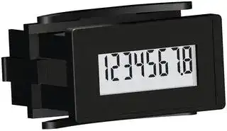
6301-2000-0000
COUNTER, 8-DIGIT LCD, 20VAC TO 300VAC
⚠️ Reference pricing provided. In case of supply shortages, we will connect you with our trusted procurement partners to ensure your project's continuity.
- Manufacturer: TRUMETER
- Product type: Counters
- Digit Height: 8mm
- Panel Cutout Width: 45.5mm
- Supply Voltage Max: 300VAC
- Supply Voltage Min: 20VAC
- Panel Cutout Height: 22.6mm
- No. of Digits / Alpha: 8
- Operating Temperature Max: 60°C
- Operating Temperature Min: -20°C
| Delivery and price | |
|---|---|
| Units per pack | 50 |
| Price | 49.42 € |
| Current stock | 10+ |
| Lead time | 7 days |
Datasheet

| | **Model 63**

**Electronic**

**LCD Counter**

## **Description**

The Model 63 Electronic Counter with 8 LCD digits brings more features to the user than ever before.  Models are available that are simple 8-digit totalizers, while other models can bring together enough features to control a signifi cant process.

A long list of features includes a programmable output, an external electronic reset, a front panel reset enable, and programmable alert or preset capability.  In addition, the unit can be confi gured to operate from an external DC power supply or an internal 15+ year lithium battery.  An EEPROM is available with the externally powered units to retain last data when power goes down.  The front end of the Model 63 Counter utilizes a high-contrast, refl ective, 8-digit LCD with 0.32 inch [8mm] digits and seven icons, while at the back end Dry Contact, Low Voltage DC, and High Voltage DC and AC Inputs are available.

The Model 63 family is designed with a rugged plastic housing that is qualifi ed to NEMA 4/4X when properly installed in a panel using a gasket that is supplied.  In addition, the unit is compliant with CE EMC standards to EN61326:2001 for industrial applications, the unit is recognized by UL for U.S. and Canadian safety standards, and it is compliant to European RoHS and WEEE standards.

## **Features**

|•|Refl ective LCD Display with 8 large (8mm) digits|Refl ective LCD Display with 8 large (8mm) digits|•|Choice of external power (with EEPROM) or internal 15+ year battery|
|---|---|---|---|---|
|•|Choice of four counter types||•|Optional Front Panel Programming for fl exible Redi-Alert or Preset|
||•|Dual Range||Counter functionality|
||•|Dual Counter|•|Optional Redi-Alert Functions|
||•|Up/Down Counter||3 Redi-Alerts are available with Front Panel Programming option<br>•|
||•|Twin Counter||4 Redi-Alerts are available with Factory Programming<br>•|
|•|Choice of I/O compliment that includes||•|Optional Preset Counter Mode|
||•|One or two inputs||Available with Front Panel Programming option or with Factory<br>•|
|||Switch Input (No voltage)<br>•||Programming|
|||Low DC Voltage (3-30VDC)<br>•|•|NEMA 4/4X, 12, and IP66 rated|
|||High Voltage (20-300VAC or 10-300VDC)<br>•|•|EMC Compliant to EN61326:2001 for industrial environments|
||•|Control Inputs|•|CE compliant, UL and cUL recognized|
|||External Electronic Reset<br>•|•|European WEEE & RoHS Compliant|
|||Front Panel Reset Enable<br>•|||
||•|Discrete Output|||
|||Open-Drain MOSFET<br>•|||


## **Capabilities**

## **Counter Operation**

Any of four different counting methods may be specifi ed in each unit.  These counting methods are factory set.

## Dual Range:

In the Dual Range Mode, the counter waits for a pulse on either Input A or Input B.  The fi rst input to have a pulse is recognized and its pulses are counted.  The other input is ignored until the counter is reset.  The rated speed for one of the inputs is 40 Hz and for the other input it is 500 Hz.  This mode is best for single up-counter operation.

## Dual Counter:

In the Dual Counter Mode, the pulses on Input A are counted in twocounters, Counter A and Counter B.  Counter A is resettable and Counter B is not. Pressing and releasing the SEL switch swaps the counters on the display.  This mode is good for maintenance applications where a total counts accumulated during operation is desired.  The Dual Counter is only available with front panel programming.

## Up/Down Counter:

In the Up/Down Counter Mode, the pulses on Input A are added to the accumulated count and the pulses on Input B are subtracted from the accumulated count.  The Up/Down Counter is capable of displaying negative numbers.

## Twin Counter:

The Twin Counter behaves as two counters in one package.  The pulses on Input A are accumulated in Counter A and the pulses on Input B are accumulated in Counter B.  Both counters are reset at the same time.  The displayed counters can be swapped by pressing and releasing the SEL switch.  The Twin Counter is only available with front panel programming.

## **I/O Functions**

The I/O functions can be mixed and matched to maximize the functionality of the counter.  There are three types of inputs that the counter can accept. The interfaces for each are factory set.  The inputs can be

**www.redingtoncounters.com**

**13**

**Electronic**

**LCD Counter**

**Model 63**

- Switch – open circuit or switch closure

- Low Voltage DC – Low input is less than 1VDC and High Input is 3 – 30VDC.

- High Voltage DC or AC – Low is less than 3VDC or 3VAC.  A High Input is either 10 – 300VDC or 20-300VAC.

For the Switch and Low Voltage DC Counters, there are six screw terminals for all of the I/O.    For the High Voltage Counters, there are four screw terminals for the I/O.  The combinations of the I/O and power supply are factory set.

Pulse Inputs: The pulse inputs are those inputs that are counted.

Remote Reset: When the remote reset is at a high level, the counter will reset.

Front Panel Reset Enable:     The counter will reset when the Front Panel Reset Enable is  at a high level, and the Front Panel Reset Switch is pressed. The counter will not reset when the Front Panel Reset Enable is at a low level and the Front Panel Reset Switch is pressed. Output: The output is an open-drain MOSFET.  The output is used when operating in the Preset Counter Mode, and it can be option ally used when using Redi-Alerts.

## **Preset Function**

Each counter may be placed in a preset operating mode.  This mode can be programmed through the front panel for those units that have the front panel programming option.  It may also be factory programmed.  IT IS NOT RECOMMENDED THAT THE PRESET FUNCTION BE USED AT THE SAME TIME THAT ALERTS ARE ENABLED.

Basically, a preset counter is a counter that counts to a preset value and then turns on an output device.  At some point, the output device is turned off, the counter is reset, and the process begins again.  There are two things to determine.  One is when and how to turn off the output device, and the second is when and how to reset the counter.

The preset counters can be set up for either automatic reset or external (front panel or remote) reset.  The outputs can be turned off by either time out or external reset.  In addition to the output, an icon can be turned on when the output is turned on for a visual indication of the preset condition.

## **Alert Functions**

The Model 63 Counter can be programmed to operate as a maintenance device in which alerts notify the user of certain maintenance actions to be taken after accumulation of a predefined number of counts.  When the accumulated count equals the predefined alert value, an icon is illuminated on the display.  When the alert is reset, the icon is turned off, but the count value is not reset.

There are two types of alerts.  The first is a break-in alert.  A break-in alert only occurs once at the start of unit operation.  The second type of alert is recurring.  A recurring alert occurs continuously at a predefined period.  When tied to a break-in alert, the recurring alert will not begin its count until the break-in alert has occurred.

The intervals for the recurring alert can be performed as start-to start or end-to-start.  A start-to-start interval count starts when the last alert is turn on. The end-to-start interval count starts when the last alert is turned off.

The Model 63 Counter can support three alerts using front panel programming and four alerts when factory programmed.  IT IS NOT RECOMMEDED THAT THE PRESET FUNCTION BE USED AT THE SAME TIME THAT ALERTS ARE ENABLED.  In both cases, Alert #1 is a break-in alert that is tied to Alert #2, which is recurring.  Alert #3 is recurring, and Alert #4 can be factory set as either break-in or recurring.  If Alert #4 is break-in, then it is tied to Alert #3.

The Model 63 Counter can be programmed to be latched or kept on for a predetermined number of counts.  When latched, an external reset is required to turn off the alert.  Each alert can also force the output on when the alert is on.

## **Front Panel**

The liquid crystal display is reflective with dark characters on a light background.  There are 8 digits on the display.  The standard display contains seven icons which can be assigned as desired to either alerts or a preset.

Model 63 Counters with the front panel programming option are capable of being programmed for either alerts or the preset function.  There are two front panel switches.  To begin programming, the two switches are pressed simultaneously.  The programming menu must be completed in its entirety to return to normal operation.  The switch functions are described as follows:

SEL: During normal operation, the displayed counters will be swapped when the SEL switch is pressed and released.  During programming, this switch is used to select options.

RST: During normal operation, the RST switch is used for front panel reset.  During programming, the RST switch is used to enter an option.

## **Resets**

Unless using alerts, a reset returns the display to zero.  If using alerts, the reset turns an alert off.  There are three different reset configurations available:

Non-Reset: The counter can never be reset.  A non-reset unit also has no front panel programming option.

Remote Reset: A model with Remote reset has a dedicated terminal for performing the reset function.  The unit resets when the remote reset signal is at a high level.  When the reset signal is at a low level, accumulating counts can occur.

Manual Reset: Manual reset occurs when the RST switch on the front of the counter is pressed.  Counting resumes upon release of the RST switch. The exception to this operation is in the Dual Counter case in which the non-resettable counter can not be reset.

Note:  Some counters are equipped with a Manual Reset Enable Input.  In this case, the Manual Reset Enable Input must be high for the RST switch to be functional.

**www.redingtoncounters.com**

**14**

LID ~~a~~ **Model 63 Electronic LCD Counter**

## **Sp**

**Display:** Figures: 8 LCD digits 0.32” [8mm] high

Annunciators Icon: A choice of 7 Icons 0.08” [2mm] high **Reset:** Remote, manual & non-reset. Manual reset enable is available on some models **Speed:** Low speed: 0-40 counts per second (min. 12.5ms-on, 12.5ms-off High speed: 0-500 counts per second (min. 1.0 ms-on, 1.0 ms-off **Inputs:** Switch (no voltage) DC Voltage: Absolute voltage range: -0.5 VDC, minimum to 30.0VDC, maximum VIH: 3.0 VDC, maximum VIL: 1.0 VDC, minimum High Voltage AC/DC: Absolute Maximum voltage:  300VAC/VDC VIH: 10VDC/20 VAC, max. VIL: 3VDC/3 VAC, minimum **Power:** Internally powered models: Self powered (+15yrs lithium battery) Externally Powered models: 5-28 VDC , externally supplied Absolute Maximum external power: 30.0 VDC

**Output:** Format: Open-Drain MOSFET with Source connected to Common (see note 3) Maximum Withstanding voltage: 30VDC, reference to Common Maximum Load current: 0.1Amp

**EEPROM:** (When installed) 40 years Maximum data writes: 100,000 **Battery Life:** 15 years + **Mounting:** Panel with clip **Terminations:** Terminal block **Weight:** 2 oz. [57g] **Environmental:** Temp. (Storage & Operating): -4˚F to + 140˚F [-20˚C to +60˚C] Humidity: 0 to 95% RH, non-condensing **Vibration:** Operating: 10 to 55 Hz, 0.01” [0.25mm] double amplitude Non-operating:        10 to 55 Hz, 0.03” [0.75mm] double amplitude **Shock:** Operating: 10G’s Non-operating: 30G’s **Dielectric:** 1000 VAC 50/60Hz for 1 minute **Accuracy:** 100% (provided signal meets stated parameters) **EMC Compliance:** EN61326:1997 with A1: 1998 & A2:2001 for industrial environments **Enclosure:** NEMA 4/4X, 12, & IP66 compliance (from the front) when properly mounted using the optional gasket **Approvals:** CE compliant, UL & cUL recognized **Environmental Compliance:** Compliant to the European WEEE & RoHS

## **Notes**

1. When interfacing the Model 63 with a Solid State Relay or AC Sensor, the leakage current needs to be considered.  Contact the factory or see the application note at www.redingtoncounters.com for further information.

2. The Absolute Voltage Range and the Absolute Maximum Voltage are the voltages at which operation beyond the specified limits may result in damage to the unit.

3. Operates like open-collector NPN.  Care should be taken when interfacing to this input since there is no current limiting protection in the counter.

## **Dimensions**

**==> picture [430 x 236] intentionally omitted <==**

**----- Start of picture text -----**<br>
1.76 [44.7]<br>1.86 [47.3]<br>2.00 [50.8] 1.50 [38.0]<br>1.31 [33.4] ee<br>— TI<br>i nl .87 [22.1] .97 [24.7]<br>.31 [8.0]<br>1.10 [27.9]<br>(homea om .02 [0.5] |<br>.48 [12.1] TE .16 [4.0]<br>Panel Cutout: 1.79” [45.5mm] x 0.89” [22.6mm]<br>Recommended Panel Thickness: 0.875” [22.2mm]<br>SERVICE OIL AIR FILTER MUFFLER<br>CHANGE OIL FILTER LAMP<br>**----- End of picture text -----**<br>


## **Available Icons**

**www.redingtoncounters.com**

**15**

|||**REDINGTON MODEL 63**<br>**PART NUMBER MATRIX**|**REDINGTON MODEL 63**<br>**PART NUMBER MATRIX**|**REDINGTON MODEL 63**<br>**PART NUMBER MATRIX**|**REDINGTON MODEL 63**<br>**PART NUMBER MATRIX**|**REDINGTON MODEL 63**<br>**PART NUMBER MATRIX**||
|---|---|---|---|---|---|---|---|
|**Function/**||**Input**|||**Reset**||**Stock**|
|**Application**||**3-30VDC**|**10-30VDC or 20-300VAC**|**Switch**|**Remote**|**Manual***|**Part Numbers****|
|**Totalizer** (8 fig.)|40/500 cps|||�|�||**6300-0000-0000**|
|||||�||�|**6300-0500-0000**|
|||�|||�||**6300-1000-0000**|
|||�||||�|**6300-1500-0000**|
||||�||�||**6301-2000-0000**|
||||�|||�|**6300-2500-0000**|
|**Hour Meter**(8 fig.)|**Hours**|||�|�||**6320-0000-0000**|
|||||�||�|**6320-0500-0000**|
|||�|||�||**6320-1000-0000**|
|||�||||�|**6320-1500-0000**|
||||�||�||**6320-2000-0000**|
||||�|||�|**6320-2500-0000**|
||**Minutes**|||�|�||**6321-0000-0000**|
|||||�||�|**6321-0500-0000**|
|||�|||�||**6321-1000-0000**|
|||�||||�|**6321-1500-0000**|
||||�||�||**6321-2000-0000**|
||||�|||�|**6321-2500-0000**|
||**Seconds**|||�|�||**6322-0000-0000**|
|||||�||�|**6322-0500-0000**|
|||�|||�||**6322-1000-0000**|
|||�||||�|**6322-1500-0000**|
||||�||�||**6322-2000-0000**|
||||�|||�|**6322-2500-0000**|
|**Tach.**|(4 fig.)|||�|||**6330-0000-0000**|
|||�|||||**6330-1000-0000**|
||||�||||**6330-2000-0000**|
|�<br>�<br>�|**_All Stock Part Numbers are:_**<br>_Panel Mount (1.79" x .89")_<br>_Self-Powered (15yr lithium battery)_<br>_Terminal Block Termination_||||_alert features, outputs, etc._<br>**_**This product can be customized_**<br>**_to meet any application._**<br>_Contact Redington for optional_|||
Updated at February 9, 2023
About Novapart
Novapart is a B2B electronic component broker specialising in stock shortages and cost reduction. We source hard-to-find parts and identify compliant alternatives across a catalogue of 410,000+ components from 500+ manufacturers.
Learn more →Stock Shortage Specialist
When a component is unavailable, discontinued or has an unacceptable lead time, we tap into our network of vetted European and Asian distributors to source what you need — without compromising on quality or traceability.
Request a quote →Compliant Alternatives
We identify pin-to-pin, electrically equivalent substitutes that meet the same certifications (RoHS, AEC-Q100, REACH) as your original specification — validated against datasheets, not just part numbers. Often at a lower cost.
BOM Analysis service →