
Image not available
Illustrative purposes only

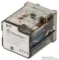
62.32.9.024.0000
Power Relay, DPDT, 24 VDC, 16 A, 62 Series, Socket
⚠️ Reference pricing provided. In case of supply shortages, we will connect you with our trusted procurement partners to ensure your project's continuity.
- Manufacturer: FINDER
- Product type: Power Relays
- Contact Configuration:DPDT; Coil Voltage:24VDC; Contact Current:16A; Product Range:62 Series; Relay Mounting:Socket; Coil Type:-; Contact Voltage VAC:250V; Relay Terminals:Quick Connect;
- SVHC: No SVHC (25-Jun-2025)
- Coil Type: -
- Coil Voltage: 24VDC
- Product Range: 62 Series
- Relay Mounting: Socket
- Coil Resistance: 445ohm
- Contact Current: 16A
- Relay Terminals: Quick Connect
- Contact Material: Silver Cadmium Oxide
- Contact Voltage VAC: 250V
- Contact Voltage VDC: -
- Approvals & Standards: CSA, UL, VDE
- Contact Configuration: DPDT
| Delivery and price | |
|---|---|
| Units per pack | 50 |
| Price | 15.23 € |
| Current stock | 10+ |
| Lead time | 30 days |
Datasheet

**62 SERIES**

**A**

## **Printed circuit mount**

## **62.22/62.23**

## **62.22-0300/62.23-0300**

## **16 A Power relay**

- 2 & 3 Pole changeover contacts or NO (≥ 3 mm contact gap)

- AC coils & DC coils

- Reinforced insulation between coil and contacts according to EN 60335-1, with 6 mm clearance & 8 mm creepage distance

- SELV coil-contact separator option

- Cadmium free contact material options

- 2 & 3 pole changeover contact

- PCB mount

   - 2 & 3 pole normally open contact (≥ 3 mm contact gap)

   - PCB mount

- Distance between contacts ≥ 3 mm (EN 60730-1).

- ** With the AgSnO2 material the maximum peak current is 120 A - 5 ms (NO contact).

_For UL ratings see: “General technical information” page_ V

**==> picture [515 x 432] intentionally omitted <==**

**----- Start of picture text -----**<br>
|||||||||||
|---|---|---|---|---|---|---|---|---|---|
|62.22|62.23|62.22 - 0300|62.23 - 0300|
|For outline drawing see page 10|Copper side view|Copper side view|Copper side view|Copper side view|
|Contact specification|
|Contact configuration|2 CO (DPDT)|3 CO (3PDT)|2 NO (DPST-NO), ≥ 3 mm*|3 NO (3PST-NO), ≥ 3 mm*|
|Rated current/Maximum peak current|A|16/30**|16/30**|
|Rated voltage/|
|Maximum switching voltage|V AC|250/400|250/400|
|Rated load AC1|VA|4000|4000|
|Rated load AC15 (230 V AC)|VA|750|750|
|Motor rating (230/400 V AC)|kW|0.8/—|0.8/1.5|0.8/—|0.8/1.5|
|Breaking capacity DC1: 30/110/220 V|A|16/0.6/0.4|16/1.1/0.7|
|Minimum switching load|mW (V/mA)|1000 (10/10)|1000 (10/10)|
|Standard contact material|AgCdO|AgCdO|
|Coil specification|
|Nominal voltage (UN)|V AC (50/60 Hz)|6 - 12 - 24 - 48 - 60 - 110 - 120 - 230 - 240 - 400|
|V DC|6 - 12 - 24 - 48 - 60 - 110 - 125 - 220|
|Rated power AC/DC|VA (50 Hz)/W|2.2/1.3|3/3|
|Operating range|AC|(0.8…1.1)UN|(0.85…1.1)UN|
|DC|(0.8…1.1)UN|(0.85…1.1)UN|
|Holding voltage|AC/DC|0.8 UN / 0.6 UN|0.8 UN / 0.6 UN|
|Must drop-out voltage|AC/DC|0.2 UN / 0.1 UN|0.2 UN / 0.1 UN|
|Technical data|
|Mechanical life AC/DC|cycles|10 · 10|[6]|/30 · 10|[6]|10 · 10|[6]|/30 · 10|[6]|
|Electrical life at rated load AC1|cycles|100 · 10|[3]|100 · 10|[3]|
|Operate/release time|ms|11/4|15/3|
|Insulation between coil|
|and contacts (1.2/50 µs)|kV|6|6|
|Dielectric strength|
|between open contacts|V AC|1500|3000|
|Ambient temperature range|°C|–40…+70|–40…+50|
|Environmental protection|RT I|RT I|
|Approvals|(according to type)|@|Hl|®|B§|RINA|Miu|s|@S&|

**----- End of picture text -----**<br>


**1**

**62 SERIES**

**A** -

## **Plug-in mount/Faston 187 16 A Power relay**

- Plug-in (92 series sockets) or Faston 187

- (4.8 x 0.5 mm) with optional mounting adaptors

- 2 & 3 Pole changeover contacts or NO (≥ 3 mm contact gap)

## **62.32/62.33**

## **62.32-0300/62.33-0300**

- AC coils & DC coils

- UL Listing (certain relay/socket combinations)

- LED, mechanical indicator & test button options

- Reinforced insulation between coil and contacts according to EN 60335-1, with 6 mm clearance & 8 mm creepage distance

- SELV coil-contact separator option

- Cadmium free contact material options

- 2 & 3 pole changeover contact

- Plug-in/Faston 187

   - 2 & 3 pole normally open contact

   - (≥ 3 mm contact gap)

   - Plug-in/Faston 187

- Sockets and accessories

- European Patent

- Distance between contacts ≥ 3 mm (EN 60730-1).

- ** With the AgSnO2 material the maximum peak current is 120 A - 5 ms (NO contact).

_For UL ratings see:_

## _“General technical information” page_ V

**==> picture [518 x 423] intentionally omitted <==**

**----- Start of picture text -----**<br>
|||||||||||
|---|---|---|---|---|---|---|---|---|---|
|For outline drawing see page 10|62.32|62.33|62.32-0300|62.33-0300|
|Contact specification|
|Contact configuration|2 CO (DPDT)|3 CO (3PDT)|2 NO (DPST-NO), ≥ 3 mm*|3 NO (3PST-NO), ≥ 3 mm*|
|Rated current/Maximum peak current|A|16/30**|16/30**|
|Rated voltage/|
|Maximum switching voltage|V AC|250/400|250/400|
|Rated load AC1|VA|4000|4000|
|Rated load AC15 (230 V AC)|VA|750|750|
|Motor rating (230/400 V AC)|kW|0.8/—|0.8/1.5|0.8/—|0.8/1.5|
|Breaking capacity DC1: 30/110/220 V|A|16/0.6/0.4|16/1.1/0.7|
|Minimum switching load|mW (V/mA)|1000 (10/10)|1000 (10/10)|
|Standard contact material|AgCdO|AgCdO|
|Coil specification|
|Nominal voltage (UN)|V AC (50/60 Hz)|6 - 12 - 24 - 48 - 60 - 110 - 120 - 230 - 240 - 400|
|V DC|6 - 12 - 24 - 48 - 60 - 110 - 125 - 220|
|Rated power AC/DC|VA (50 Hz)/W|2.2/1.3|3/3|
|Operating range|AC|(0.8…1.1)UN|(0.85…1.1)UN|
|DC|(0.8…1.1)UN|(0.85…1.1)UN|
|Holding voltage|AC/DC|0.8 UN / 0.6 UN|0.8 UN / 0.6 UN|
|Must drop-out voltage|AC/DC|0.2 UN / 0.1 UN|0.2 UN / 0.1 UN|
|Technical data|
|Mechanical life AC/DC|cycles|10 · 10|[6]|/30 · 10|[6]|10 · 10|[6]|/30 · 10|[6]|
|Electrical life at rated load AC1|cycles|100 · 10|[3]|100 · 10|[3]|
|Operate/release time|ms|11/4|15/3|
|Insulation between coil|
|and contacts (1.2/50 µs)|kV|6|6|
|Dielectric strength|
|between open contacts|V AC|1500|3000|
|Ambient temperature range|°C|–40…+70|–40…+50|
|Environmental protection|RT I|RT I|
|Approvals|(according to type)|
|C€@|GEA|@|B|RINA|Ws|

**----- End of picture text -----**<br>


**2**

**62 SERIES**

**A**

## **Flange mount/Faston 250 16 A Power relay**

## **62.82/62.83**

## **62.82-0300/62.83-0300**

- Faston 250 (6.3 x 0.8 mm) termination Flange or optional mounting adaptors

- 2 & 3 Pole changeover contacts or NO (≥ 3 mm contact gap)

- AC coils & DC coils

- LED, mechanical indicator & test button options

- Reinforced insulation between coil and contacts according to EN 60335-1, with 6 mm clearance & 8 mm creepage distance

- SELV coil-contact separator option

- Cadmium free contact material options

- European Patent

- 2 & 3 pole changeover contact

- Flange mount/Faston 250

   - 2 & 3 pole normally open contact (≥ 3 mm contact gap)

   - Flange mount/Faston 250

- Distance between contacts ≥ 3 mm (EN 60730-1).

- ** With the AgSnO2 material the maximum peak current is 120 A - 5 ms (NO contact).

## _For UL ratings see:_

_“General technical information” page_ V

||For outline drawing see page 10||62.82|62.83|||||62.82-0300<br>62.83-0300|
|---|---|---|---|---|---|---|---|---|---|
||**Contact specification**|||||||||
||Contact configuration||2 CO (DPDT)|3 CO (3PDT)|||||2 NO (DPST-NO),≥3 mm*<br>3 NO (3PST-NO),≥3 mm*|
||Rated current/Maximum peak current<br>A||16/30**||||||16/30**|
||Rated voltage/<br>Maximum switchingvoltage|V AC|250/400||||||250/400|
||Rated load AC1|VA|4000||||||4000|
||Rated load AC15 (230 V AC)|VA|750||||||750|
||Motor rating (230/400 V AC)|kW|0.8/—|0.8/1.5|||||0.8/—<br>0.8/1.5|
||Breaking capacity DC1: 30/110/220 V<br>A||16/0.6/0.4||||||16/1.1/0.7|
||Minimum switching load|mW (V/mA)|1000 (10/10)||||||1000 (10/10)|
||Standard contact material<br>**Coil specification**||AgCdO||||||AgCdO|
||Nominal voltage (UN)|V AC (50/60 Hz)|6 - 12 - 24 - 48 - 60 - 110 - 120 - 230 - 240 - 400||||||6 - 12 - 24 - 48 - 60 - 110 - 120 - 230 - 240 - 400|
|||V DC||6 - 12 - 24 - 48 - 60 - 110 - 125 - 220|||||6 - 12 - 24 - 48 - 60 - 110 - 125 - 220|
||Rated power AC/DC|VA (50 Hz)/W|2.2/1.3||||||3/3|
||Operating range|AC|(0.8…1.1)UN||||||(0.85…1.1)UN|
|||DC|(0.8…1.1)UN||||||(0.85…1.1)UN|
||Holding voltage|AC/DC|0.8 UN/ 0.6 UN||||||0.8 UN/ 0.6 UN|
||Must drop-out voltage<br>**Technical data**|AC/DC|0.2 UN/ 0.1 UN||||||0.2 UN/ 0.1 UN|
||Mechanical life AC/DC|cycles|10 · 106/30 · 106||||||10 · 106/30 · 106|
||Electrical life at rated load AC1|cycles|100 · 103||||||100 · 103|
||Operate/release time|ms|11/4||||||15/3|
||Insulation between coil|||||||||
||and contacts(1.2/50µs)|kV|6||||||6|
|II-2018, www.findernet.com|Dielectric strength<br>between open contacts<br>Ambient temperature range<br>Environmental protection<br>**Approvals**(according to type)|V AC<br>°C|1500<br>–40…+70<br>RT I<br>~~C€@~~|~~GEA©~~|~~©~~||||3000<br>–40…+50<br>RT I<br>~~RINA.cAXus~~|


**3**

**62 SERIES**

## **Plug-in mount/Faston 187 Magnetic blow power relay**

**==> picture [51 x 8] intentionally omitted <==**

**----- Start of picture text -----**<br>
62.31-4800<br>**----- End of picture text -----**<br>


## **62.32-4800**

- Plug-in (92 series sockets) or Faston 187

**A**

- (4.8 x 0.5 mm) with optional mounting adaptors

- 1 & 2 Pole NO contacts

- High DC load (resistive and inductive) switching capability

- DC coils

- Reinforced insulation between coil and contacts according to EN 60335-1, with 6 mm clearance & 8 mm creepage distance

- Cadmium free contact material

- Sockets and accessories

- 1 pole normally open contact (double break, • 2 pole normally open contact ≥ 4.2 mm contact gap) (≥ 2.1 mm contact gap)

- Plug-in/Faston 187

   - Plug-in/Faston 187

- Maximum peak current 120 A - 5 ms.

62.31-4800 62.32-4800

For outline drawing see page 10

|For outline drawing see page 10||62.31-4800|62.32-4800||
|---|---|---|---|---|
|**Contact specification**<br>Contact configuration||1 NO (SPST-NO) double break, ≥ 4.2 mm|2 NO (DPST-NO), ≥ 2.1 mm||
|Rated current/Maximum peak current<br>A||16/30*|16/30*||
|Rated voltage/<br>Maximum switchingvoltage|V AC|250/400|250/400||
|Rated load AC1|VA|4000|4000||
|Breaking capacity DC1: 30/125/220 V|A|16/16/12|16/12/6||
|Breaking capacity DC inductive (L/R = 40 ms):<br>30/125/220 V|Breaking capacity DC inductive (L/R = 40 ms):<br>A|16/5/3|10/2/1.2||
|Minimum switching load|mW (V/mA)|1000 (10/10)|1000 (10/10)||
|Standard contact material||AgSnO2|AgSnO2||
|**Coil specification**<br>Nominal voltage (UN)|V DC|6 - 12 - 24 - 48 - 60 - 110 - 125 - 220|||
|Rated power DC|W|1.3|1.3||
|Operating range|DC|(0.85…1.1)UN|(0.85…1.1)UN||
|Holding voltage|DC|0.6 UN|0.6 UN||
|Must drop-out voltage<br>**Technical data**|DC|0.1 UN|0.1 UN||
|Mechanical life DC|cycles|10 · 106|10 · 106||
|Electrical life at rated load DC1|cycles|100 · 103|100 · 103||
|Operate/release time|ms|16/5|16/5||
|Insulation between coil|||||
|and contacts(1.2/50µs)|kV|kV<br>6|6||
|Dielectric strength<br>between open contacts<br>Ambient temperature range<br>Environmental protection<br>**Approvals**(according to type)|V AC<br>°C|3000<br>–40…+70<br>RT I|2000<br>–40…+70<br>RT I|II-2018, www.findernet.com|


**4**

**62 SERIES**

**A**

## **Ordering information**

Example:  62 series power relay + Faston 250 (6.3 x 0.8 mm), rear flange mount, 2 NO (DPST-NO), 12 V DC coil.

**A B C D 6 2 . 8 2 . 9 . 0 1 2 . 0 3 0 0 Series A: Contact material D: Special versions**

## **D: Special versions**

   - 0 = Standard

- 0 = Standard AgCdO 4 =  AgSnO2 (standard for versions 4800)

## **Type**

   - 6 = Rear flange mount 9 =  Type 62.82/83 without rear flange mount

- 2 = PCB

- 3 = Plug-in 8 =  Faston 250 (6.3 x 0.8 mm) with rear flange mount

**B: Contact circuit**

   - **C: Options** 0 = None 2 = Mechanical indicator 3 = LED (AC) 4 =  Lockable test button + mechanical indicator

- 0 = CO (nPDT)

- 3 =  NO (nPST),

## **No. of poles**

   - ≥ 3 mm contact gap

   - 5 =  CO (nPDT) + additional physical separator between coil and contacts (for SELV applications)

- 1 = 1 pole (double break) 2 = 2 pole

- 3 = 3 pole

**Coil version**

      - 5* = Lockable test button + LED (AC)

   - 6 =  NO (nPST), ≥ 3 mm contact gap + additional physical separator between coil and contacts (for SELV applications) 6* =  LED + diode

- 8 = AC (50/60 Hz)

   - 54* =  Lockable test button + LED (AC) + mechanical indicator

- 9 = DC

**Coil voltage** See coil specifications

      - (DC, polarity positive to pin A/A1)

- 8 =  NO (1 pole double break or 2 pole) with magnetic blow 7* =  Lockable test button + LED + diode

      - (DC, polarity positive to pin A/A1)

   - 74* =  Lockable test button + LED + diode (DC, polarity positive to pin A/A1) + mechanical indicator

*  Options not available for 220 V DC and 400 V AC versions.

**Selecting features and options: only combinations in the same row are possible.** Preferred selections for best availability are shown in **bold.**

|**Type**<br>~~a~~|**Coil version**|**A**|**B**|**C**|**D**|
|---|---|---|---|---|---|
|62.22/23<br>~~a~~<br>~~a~~|AC-DC<br>|**0**- 4<br>|**0**- 3 - 5 - 6<br>|**0**<br>|**0**<br>|
|62.32/33<br>~~a a~~<br>~~a~~<br>~~es~~<br>~~a~~<br>~~a~~<br>~~a~~<br>~~a~~<br>~~a~~<br>~~a~~|AC-DC<br>~~a~~<br>~~a~~|0 - 4<br>~~ee~~<br>~~ee~~|0 - 3 - 5 - 6<br>~~ee~~<br>~~ee~~|0<br>~~ee~~|0  -  6<br>~~ee~~|
||AC-DC<br>~~a ~~<br>~~a~~<br>~~es~~|**0**- 4<br> ~~ee~~<br>~~ee~~|**0**- 5<br>~~ee~~<br>~~ee~~|2 -**4**<br>~~ee~~|**0**- 6<br>~~ee~~|
||AC<br>~~a~~<br>~~es~~|**0**- 4<br>~~ee~~|**0**<br>~~ee~~|2 - 3 -**4**- 5|**0**- 6|
||AC<br>~~es~~<br>~~a~~|0 - 4|0 - 3|3|0 - 6|
||AC<br>~~a~~|0 - 4|0|54|/|
||DC<br>~~a ~~|**0**- 4<br> ~~ee~~|**0**<br>~~ee~~|**4**- 6 - 7<br>~~ee~~|**0**- 6<br>~~ee~~|
||DC<br>~~a ~~<br>~~a~~<br>|0 - 4<br> ~~ee~~<br>~~ee~~<br>|0 - 3<br>~~ee~~<br>|6<br>~~ee~~<br>|0 - 6<br>~~ee~~<br>|
||DC<br>~~a~~<br>|0 - 4<br>~~ee~~<br>|0<br>|74<br>|/<br>|
|62.31/32<br>~~a~~<br>~~a ~~|DC<br>~~a~~<br>|**4**<br>~~ee~~<br>|**8**<br>|**0**<br>|**0**<br>|
|62.82/83<br> ~~aPo~~<br>~~a~~<br>~~es~~<br>~~a~~<br>~~es~~|AC-DC<br>~~a~~|**0**- 4<br>|**0**- 3 - 5 - 6<br>|**0**<br>|**0**- 9<br>|
||AC-DC<br>~~aPo~~<br>~~a~~|0 - 4<br>~~Po~~<br>~~ee~~|0 - 5<br>~~Po~~<br>~~ee~~|2 - 4<br>~~Po~~<br>~~ee~~|0<br>~~Po~~<br>~~ee~~|
||AC<br>~~Po~~<br>~~a~~<br>~~es~~|0 - 4<br>~~Po~~<br>~~ee~~|0<br>~~Po~~<br>~~ee~~|2 - 3 - 4 - 5<br>~~Po~~<br>~~ee~~|0<br>~~Po~~<br>~~ee~~|
||AC<br>~~a~~<br>~~es~~|0 - 4<br>~~ee~~|0 - 3<br>~~ee~~|3<br>~~ee~~|0<br>~~ee~~|
||DC<br>~~es~~<br>~~a~~<br>~~es~~|0 - 4|0|4 - 6 - 7|0|
||DC<br>~~es~~|0 - 4|0 - 3|6|0|


## **Descriptions: Options and Special versions**

**C: Option 3, 5, 54 C: Option 6, 7, 74** LED (AC) LED + diode (DC, polarity positive to pin A/A1)

**==> picture [171 x 93] intentionally omitted <==**

**----- Start of picture text -----**<br>
1 3<br>Ornaee<br>eT -=|<br>2<br>II-2018, www.findernet.com<br>**----- End of picture text -----**<br>


**B: Contact circuit 8** Magnetic blow

**B: Contact circuit 5, 6** Additional physical separator between coil and contacts

(for SELV applications) **Lockable test button and mechanical flag indicator (0040, 0050, 0054, 0070, 0074)** The dual-purpose Finder test button can be used in two ways: E

Case 1) The plastic pip (located directly above the test button) remains intact. In this case, when the test button is pushed, the contacts operate. When the test button is released the contacts return to their former state.

Case 2) The plastic pip is broken-off (using an appropriate cutting tool). In this case, (in addition to the above function), when the test button is pushed and rotated, the contacts are latched in the operating state, and remain so until the test button is rotated back to its former position. In both cases ensure that the test button actuation is swift and decisive.

**5**

**62 SERIES**

## **Technical data**

**A**

|**Insulation according to EN 61810-1**|**Insulation according to EN 61810-1**|||||||||
|---|---|---|---|---|---|---|---|---|---|
|||**2 CO - 3 CO**||**2 NO - 3 NO**||**1 NO***||**2 NO***||
|Nominal voltage of supply system<br>V AC||230/400||230/400||230/400||230/400||
|Rated insulation voltage<br>V AC||400||400||400||400||
|Pollution degree||3||3||3||3||
|**Insulation between coil and contact set**||||||||||
|Type of insulation||Reinforced||Reinforced||Reinforced||Reinforced||
|Overvoltage category||III||III||III||III||
|Rated impulse voltage<br>kV (1.2/50 µs)||6||6||6||6||
|Dielectric strength<br>V AC||4000||4000||4000||4000||
|**Insulation between adjacent contacts**||||||||||
|Type of insulation||Basic||Basic||—||Basic||
|Overvoltage category||III||III||—||III||
|Rated impulse voltage<br>kV (1.2/50 µs)||4||4||—||4||
|Dielectric strength<br>V AC||2500||2500||—||2500||
|**Insulation between open contacts**||||||||||
|Type of disconnection||Micro-disconnection||Full-disconnection||Full-disconnection||Full-disconnection**||
|Overvoltage category||—||III||III||II||
|Rated impulse voltage<br>kV (1.2/50 µs)||—||4||4||2.5||
|Dielectric strength<br>V AC/kV (1.2/50 µs)||1500/2||3000/4||3000/4||2000/2.5||
|**Conducted disturbance immunity**||||||||||
|Burst (5...50)ns, 5 kHz, on A1 - A2 according to EN 61000-4-4||level 4 (4 kV)||||||||
|Surge (1.2/50 µs) on A1 - A2 (differential mode) according to EN 61000-4-5||level 4 (4 kV)||||||||
|**Other data**||||||||||
|Bounce time: NO/NC<br>ms||1/5<br>(changeover)||3/—<br>(normallyopen)||3/—<br>(normallyopen)||3/—<br>(normallyopen)||
|Vibration resistance (10…150)Hz: NO/NC<br>g||20/8||||||||
|Shock resistance|g|15||||||||
|Power lost to the environment|without contact current<br>W|**2 pole (CO) **|**3 pole (CO) **||**2 pole (NO) **|**3 pole (NO) **|**1 pole (NO)***||**2 pole (NO)***|
|||1.3|1.3||3|3|1.3||1.3|
||with rated current<br>W|3.3|4.3||5|6|3||3.3|
|Recommended distance between relays mounted on PCB<br>mm||≥ 5|||||—|||


* Magnetic blow version

** Only in applications where over voltage category II is permitted. In applications of over voltage category III: Micro-disconnection.

**6**

**62 SERIES**

**A**

## **Contact specification**

## **F 62 - Electrical life (AC) v contact current**

**==> picture [511 x 317] intentionally omitted <==**

**----- Start of picture text -----**<br>
Resistive load - cos ϕ  = 1<br>Inductive load - cos ϕ  = 0.4<br>H 62 -  Maximum DC1 breaking capacity  H 62 -  Maximum DC1 breaking capacity<br>Changeover contacts Normally open contacts<br>contacts in series contacts in series<br>Voltage DC (V) Voltage DC (V)<br>Cycles<br>DC breaking current (A) DC breeaking current (A)<br>**----- End of picture text -----**<br>


- When switching a resistive load (DC1) having voltage and current values under the curve, an electrical life of ≥ 100 · 10[3] can be expected.

- In the case of DC13 loads, the connection of a diode in parallel with the load will permit a similar electrical life as for a DC1 load. Note: the release time of the load will be increased.

## **H 62 - Maximum DC breaking capacity 62.31.9.xxx.4800**

## **H 62 - Maximum DC breaking capacity 62.32.9.xxx.4800**

**==> picture [511 x 143] intentionally omitted <==**

**----- Start of picture text -----**<br>
50 50<br>DC1 DC1<br>10 10<br>DC13<br>1 L/R = 40 ms 1 DC13<br>L/R = 40 ms<br>0.1 0.1<br>20 60 100 140 180 220 260 20 60 100 140 180 220 260<br>(V) (V)<br>Voltage DC (V) Voltage DC (V)<br>DC breaking current (A) DC breeaking current (A)<br>**----- End of picture text -----**<br>


- When switching a resistive load (DC1), or a DC13 load with a diode in parallel to the load, having voltage and current values under the DC1 curve, an electrical life of ≥ 100 · 10[3] can be expected. Note: the release time for the load will be increased.

- When switching a DC13 load without a diode in parallel to the load, the DC13 curve applies and an electrical life of ≥ 80 · 10[3] can be expected.

**7**

**62 SERIES**

## **Coil specifications**

||**Coil specifications**|**Coil specifications**|**Coil specifications**|**Coil specifications**|**Coil specifications**|**Coil specifications**|
|---|---|---|---|---|---|---|
|**A**|**DC version data**||||||
||Nominal<br>voltage<br>UN|Coil<br>code|Operating range<br>Umin<br>Umax||Resistance<br>R|Rated coil<br>consumption<br>Iat UN|
||V||V|V|Ω|mA|
||6|**9**.006|4.8|6.6|28|214|
||12|**9**.012|9.6|13.2|110|109|
||24|**9**.024|19.2|26.4|445|54|
||48|**9**.048|38.4|52.8|1770|27|
||60|**9**.060|48|66|2760|21.7|
||110|**9**.110|88|121|9420|11.7|
||125|**9**.125|100|138|12000|10.4|
||220|**9**.220|176|242|37300|5.8|


## **DC (NO/nPST-NO) version data - ≥ 3 mm**

|Nominal<br>voltage<br>UN|Coil<br>code|Operating range<br>Umin<br>Umax|Operating range<br>Umin<br>Umax|Resistance<br>R|Rated coil<br>consumption<br>Iat UN|
|---|---|---|---|---|---|
|V||V|V|Ω|mA|
|6|**9**.006|5.1|6.6|12|500|
|12|**9**.012|10.2|13.2|48|250|
|24|**9**.024|20.4|26.4|192|125|
|48|**9**.048|40.8|52.8|770|63|
|60|**9**.060|51|66|1200|50|
|110|**9**.110|93.5|121|4200|26|
|125|**9**.125|106|138|5200|24|
|220|**9**.220|187|242|17600|12.5|


## **AC version data**

**==> picture [253 x 47] intentionally omitted <==**

**----- Start of picture text -----**<br>
Nominal  Coil  Rated coil<br>voltage code Operating range Resistance consumption<br>UN Umin Umax R I at UN (50Hz)<br>V V V Ω mA<br>**----- End of picture text -----**<br>


|Nominal<br>voltage<br>UN<br>V|Coil<br>code|Operating range<br>Umin<br>Umax<br>V<br>V|Operating range<br>Umin<br>Umax<br>V<br>V|Resistance<br>R<br>Ω|Rated coil<br>consumption<br>Iat UN(50Hz)<br>mA|
|---|---|---|---|---|---|
|6|**8**.006|4.8|6.6|4.6|367|
|12|**8**.012|9.6|13.2|19|183|
|24|**8**.024|19.2|26.4|74|90|
|48|**8**.048|38.4|52.8|290|47|
|60|**8**.060|48|66|450|37|
|110|**8**.110|88|121|1600|20|
|120|**8**.120|96|132|1940|18.6|
|230|**8**.230|184|253|7250|10.5|
|240|**8**.240|192|264|8500|9.2|
|400|**8**.400|320|440|19800|6|


## **AC (NO/nPST-NO) version data - ≥ 3 mm**

**==> picture [253 x 47] intentionally omitted <==**

**----- Start of picture text -----**<br>
Nominal  Coil  Rated coil<br>voltage code Operating range Resistance consumption<br>UN Umin Umax R I at UN (50Hz)<br>V V V Ω mA<br>**----- End of picture text -----**<br>


|Nominal<br>voltage<br>UN<br>V|Coil<br>code|Operating range<br>Umin<br>Umax<br>V<br>V|Operating range<br>Umin<br>Umax<br>V<br>V|Resistance<br>R<br>Ω|Rated coil<br>consumption<br>Iat UN(50Hz)<br>mA|
|---|---|---|---|---|---|
|6|**8**.006|5.1|6.6|4|540|
|12|**8**.012|10.2|13.2|14|275|
|24|**8**.024|20.4|26.4|62|130|
|48|**8**.048|40.8|52.8|220|70|
|60|**8**.060|51|66|348|55|
|110|**8**.110|93.5|121|1200|30|
|120|**8**.120|106|137|1350|24|
|230|**8**.230|196|253|5000|14|
|240|**8**.240|204|264|6300|12.5|
|400|**8**.400|340|440|14700|7.8|


## **DC (NO/nPST-NO) magnetic blow version - ≥ 2.1 mm or ≥ 4.2 mm**

|Nominal<br>voltage<br>UN|Coil<br>code|Operating range<br>Umin<br>Umax|Operating range<br>Umin<br>Umax|Resistance<br>R|Rated coil<br>consumption<br>Iat UN|
|---|---|---|---|---|---|
|V||V|V|Ω|mA|
|6|**9**.006|5.1|6.6|28|214|
|12|**9**.012|10.2|13.2|110|109|
|24|**9**.024|20.4|26.4|445|54|
|48|**9**.048|40.8|52.8|1770|27|
|60|**9**.060|51|66|2760|21.7|
|110|**9**.110|93.5|121|9420|11.7|
|125|**9**.125|106|138|12000|10.4|
|220|**9**.220|154*|242|37300|5.8|


* Special version with Umin = 70% UN

**8**

**62 SERIES**

**A**

## **Coil specifications**

**==> picture [191 x 19] intentionally omitted <==**

**----- Start of picture text -----**<br>
R 62 -  DC coil operating range v ambient temperature<br>Changeover contacts<br>**----- End of picture text -----**<br>


**==> picture [191 x 19] intentionally omitted <==**

**----- Start of picture text -----**<br>
R 62 -  AC coil operating range v ambient temperature<br>Changeover contacts<br>**----- End of picture text -----**<br>


**==> picture [511 x 142] intentionally omitted <==**

**1 -** Max. permitted coil voltage.

**2 -** Min. pick-up voltage with coil at ambient temperature.

**1 -** Max. permitted coil voltage.

**==> picture [192 x 9] intentionally omitted <==**

**----- Start of picture text -----**<br>
2 -   Min. pick-up voltage with coil at ambient temperature.<br>**----- End of picture text -----**<br>


**R 62 -  DC coil operating range v ambient temperature** Normally open contacts

**R 62 -  AC coil operating range v ambient temperature** Normally open contacts

**==> picture [511 x 142] intentionally omitted <==**

**1 -** Max. permitted coil voltage. **1 -** Max. permitted coil voltage. **2 -** Min. pick-up voltage with coil at ambient temperature. **2 -** Min. pick-up voltage with coil at ambient temperature.

## **R 62 -  DC coil operating range v ambient temperature**

Normally open contacts - magnetic blow version

**==> picture [251 x 142] intentionally omitted <==**

**1 -** Max. permitted coil voltage.

**2 -** Min. pick-up voltage with coil at ambient temperature.

**9**

**62 SERIES**

## **Outline drawings**

Type  62.22 Type  62.23 Type 62.2x Type 62.2x-0300 62.22-0300 62.23-0300 **A** Type  62.32 Type  62.33 Type 62.3x Type 62.3x-0300 62.32-0300 62.33-0300 Type  62.82 Type  62.83 Type 62.8x Type 62.8x-0300 62.82-0300 62.83-0300

**==> picture [303 x 124] intentionally omitted <==**

Type 62.31-4800 Type 62.32-4800

**==> picture [54 x 107] intentionally omitted <==**

**==> picture [66 x 111] intentionally omitted <==**

**==> picture [66 x 111] intentionally omitted <==**

**10**

**62 SERIES**

**A**

## **Accessories**

**==> picture [409 x 685] intentionally omitted <==**

**----- Start of picture text -----**<br>
Mounting adaptor  for types 62.3x and 62.8x.xxxx.xxx9 (M4)  062.10<br>=a S a<br>2 2.” 305 97 45.6 2<br>062.10<br>| — 48<br><< LT<br>ie 6 | a e | 8<br>a | 472<br>i m a<br>062.10 with relay 062.10 062.10 with relay<br>Flange mounting adaptor  for types 62.3x and 62.8x.xxxx.xxx9  062.60<br>ce 41<br>45.6<br>062.60<br>N<br>ag - ——<br>o x sa |<br>: e 88, : [ae] y C]QS==<br>062.60 with relay - oT<br>fapNe1 LA)1 X o ) |<br>062.60 062.60 with relay<br>Top flange mount  for types 62.3x and 62.8x.xxxx.xxx9  062.05<br>40.6<br>i | 28 3 46.1 1.7 3. 6<br>SS — 062.05 = ASH<br>=I N la 2 s7_|58 | 59<br>U ;<br>062.05 with relay 062.05 062.05 with relay<br>Top 35 mm rail (EN 60715) mount  for types 62.3x and 62.8x.xxxx.xxx9 062.07<br>78 40.6<br>—J 30 ) 55 I" 1 |S “<br>=a =O2<br>062.07 s ea l ls x<br>i im !<br>15, 3 46.1 ©rey 44<br>CT<br>062.07 with relay 062.07 062.07 with relay<br>Rear 35 mm rail (EN 60715) mount  for types 62.3x and 62.8x.xxxx.xxx9 062.08<br>=<br>Eee 062.08 | Pa p<br>ae, | ea 7 eal<br>+ Oo | jm ie = v<br>3 51.4 406 | _<br>062.08 with relay 062.08 062.08 with relay<br>Sheet of marker tags (CEMBRE Thermal transfer printers)  for 62 series relays,<br>060.48<br>plastic, 48 tags, 6 x 12 mm<br>**----- End of picture text -----**<br>


**060.48**

**11**

**62 SERIES**

**==> picture [10 x 10] intentionally omitted <==**

**----- Start of picture text -----**<br>
A<br>**----- End of picture text -----**<br>


**==> picture [65 x 29] intentionally omitted <==**

**----- Start of picture text -----**<br>
92.03<br>Approvals<br>(according to type):<br>**----- End of picture text -----**<br>


|**Screw terminal (Box clamp) socket**<br>panel or 35 mm rail (EN 60715) mount<br>For relay type<br>**Accessories**<br>Metal retaining clip<br>(supplied with socket -packagingcode SMA)|**92.03**<br>**Blue**<br>**92.03.0**<br>**Black**<br>62.31, 62.32, 62.33<br>092.71|**92.03**<br>**Blue**<br>**92.03.0**<br>**Black**<br>62.31, 62.32, 62.33<br>092.71|
|---|---|---|
|Identification tag|092.00.2||
|Modules (see table below)|99.02||
|Timer modules (see table below)<br>**Technical data**<br>Rated values|86.00, 86.30<br>16 A - 250 V||
|Dielectric strength|6 kV (1.2/50µs) between coil and contacts||
|Protection category|IP 20||
|Ambient temperature<br>°C|–40…+70 (see diagram L92)||
|Screw torque<br>Nm|0.8||
|Wire striplength<br>mm|10||
|Max. wire size for 92.03 socket<br>mm2 <br>AWG|solid wire|stranded wire|
||1 x 10 / 2 x 4|1 x 6 / 2 x 4|
||1 x 8 / 2 x 12|1 x 10 / 2 x 12|


## **L 92 - Rated current v ambient temperature**

a a DS No 6 | oe a ON c ie | a ~~a a a a -~~ See ~~_s~~ a ~~a OO~~ > ~~P~~ oso)] tis fp c a a a ~~OO~~ Se ol , ag “pp a ~~| ¢y~~ d 6 ~~A~~ pss * ~~-~~ 20 0 20 40 60 (°C)80 7 col ~~f~~ —ale Et ~~|~~ x ms » **86 series timer modules** Multi-voltage: (12…240)V AC/DC; Multi-functions: AI, DI, SW, BE, CE, DE, EE, FE; (0.05 s…100 h) 86.00.0.240.0000 (12…24)V AC/DC; Bi-function: AI, DI; (0.05 s…100 h) 86.30.0.024.0000 (110...125)V AC; Bi-function: AI, DI; (0.05 s…100 h) 86.30.8.120.0000 **86.00** (230...240)V AC; Bi-function: AI, DI; (0.05 s…100 h) 86.30.8.240.0000 ~~—————~~ hi ay, Approvals . (according to type):

**==> picture [18 x 6] intentionally omitted <==**

**----- Start of picture text -----**<br>
86.30<br>**----- End of picture text -----**<br>


**==> picture [18 x 6] intentionally omitted <==**

**----- Start of picture text -----**<br>
99.02<br>**----- End of picture text -----**<br>


Approvals (according to type):

DC Modules with non-standard polarity (+A2) on request.

|Diode (+A1, standardpolarity)<br>(6...220)V DC|99.02.3.000.00|
|---|---|
|LED<br>(6...24)V DC/AC|99.02.0.024.59|
|LED<br>(28...60)V DC/AC|99.02.0.060.59|
|LED<br>(110...240)V DC/AC|99.02.0.230.59|
|LED + Diode (+A1, standardpolarity)<br>(6...24)V DC|99.02.9.024.99|
|LED + Diode (+A1, standardpolarity)<br>(28...60)V DC|99.02.9.060.99|
|LED + Diode (+A1, standardpolarity)<br>(110...220)V DC|99.02.9.220.99|
|LED + Varistor<br>(6...24)V DC/AC|99.02.0.024.98|
|LED + Varistor<br>(28...60)V DC/AC|99.02.0.060.98|
|LED + Varistor<br>(110...240)V DC/AC|99.02.0.230.98|
|RC circuit<br>(6...24)V DC/AC|99.02.0.024.09|
|RC circuit<br>(28...60)V DC/AC|99.02.0.060.09|
|RC circuit<br>(110...240)V DC/AC|99.02.0.230.09|
|Residual current by-pass<br>(110...240)V AC|99.02.8.230.07|


**12**

**62 SERIES**

**PCB socket 92.13 (blue) 92.13.0 (black)** For relay type 62.31, 62.32, 62.33 **Accessories** et **92.13** Metal retaining clip Approvals (supplied with socket - packaging code SMA) 092.54 (according to type): **Technical data** @ FAL AXis@ Rated values 10 A - 250 V Dielectric strength 2.5 kV AC Ambient temperature °C –40…+70 ~~40~~ 1 38 1 19.3 83. 65 124 222 323, g ~~l~~ i o¢ 6 6 * a ’ 1 © te Le Lita ee e ~~H~~ FSeeei” ia “y i ialeleieieleieieieient ~~3.4~~ 62.3x plug on 92.13 is 63.3 mm high

**==> picture [10 x 10] intentionally omitted <==**

**----- Start of picture text -----**<br>
A<br>**----- End of picture text -----**<br>


**==> picture [374 x 105] intentionally omitted <==**

**----- Start of picture text -----**<br>
|||||||
|---|---|---|---|---|---|
|Panel mount solder socket|mounted with M3 screw|92.33 (blue)|
|For relay type|62.31, 62.32, 62.33|
|Accessories|
|92.33|Metal retaining clip|
|Approvals|(supplied with socket - packaging code SMA)|092.54|
|(according to type):|
|Technical data|
|Ce|@|FAL|®|Rated values|10 A - 250 V|
|CALs|Dielectric strength|2.5 kV AC|
|Ambient temperature|°C|–40…+70|

**----- End of picture text -----**<br>


## **Packaging codes**

**How to code and identify retaining clip and packaging options for sockets.**

Example:

**9 2 . 0 3 S M A**

**9 2 . 0**

**==> picture [9 x 11] intentionally omitted <==**

**----- Start of picture text -----**<br>
3<br>**----- End of picture text -----**<br>


**A** Standard packaging **SM** Metal retaining clip Without retaining clip

Please see general technical information

**13**
Updated at June 7, 2026
About Novapart
Novapart is a B2B electronic component broker specialising in stock shortages and cost reduction. We source hard-to-find parts and identify compliant alternatives across a catalogue of 410,000+ components from 500+ manufacturers.
Learn more →Stock Shortage Specialist
When a component is unavailable, discontinued or has an unacceptable lead time, we tap into our network of vetted European and Asian distributors to source what you need — without compromising on quality or traceability.
Request a quote →Compliant Alternatives
We identify pin-to-pin, electrically equivalent substitutes that meet the same certifications (RoHS, AEC-Q100, REACH) as your original specification — validated against datasheets, not just part numbers. Often at a lower cost.
BOM Analysis service →