
Image not available
Illustrative purposes only

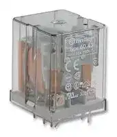
60.42.8.230.0000
General Purpose Relay, 60 Series, Power, DPDT, 230 VAC, 10 A
⚠️ Reference pricing provided. In case of supply shortages, we will connect you with our trusted procurement partners to ensure your project's continuity.
- Manufacturer: FINDER
- Product type: Power Relays
- Coil Voltage: 230VAC
- Product Range: 60
- Relay Mounting: Through Hole
- Coil Resistance: 7.25kohm
- Contact Current: 10A
- Relay Terminals: Solder
- Contact Material: Silver Nickel
- Contact Voltage VAC: 250VAC
- Approvals & Standards: CE, CSA, UL, VDE
- Contact Configuration: DPDT
| Delivery and price | |
|---|---|
| Units per pack | 50 |
| Price | 16.48 € |
| Current stock | 10+ |
| Lead time | 30 days |
Datasheet

**60 Series - General purpose relays 6 - 10 A**

**60**

## **Features**

## **60.12**

## **60.13**

## **Plug-in mount 10 A General purpose relay**

- 2 & 3 pole changeover contacts

- Cadmium Free contacts (preferred version)

- AC coils & DC coils

- UL Listed (certain relay/socket combinations)

- Contact material options

- Lockable test button with mechanical flag indicator (preferred version)

- 2 pole - 10 A power contacts

- 8 pin plug-in

   - 3 pole - 10 A power contacts

   - • 11 pin plug-in

- 90 series sockets, coil EMC suppression and timer accessories

**12** 4 **22** 5 **22** 5 **21** 6 **24** 7 **14** 3 **24** 6 **12** 4 **32** 8 **11** 1 **21** 8 **14** 3 **34** 9 **11** 1 **31** 11 **A1** 2 **A2** 7 as aa **A1** 2 **A2** 10 **32.5 36.4 32.5 36.4** ~~= =| 2~~ TOL ~~i TO~~ **Contact specification** Contact configuration 2 CO (DPDT) 3 CO (3PDT) Rated current/Maximum peak current A ~~a~~ 10/20 10/20 Rated voltage/Maximum switching voltage V AC ~~a~~ 250/400 250/400 Rated load AC1 VA ~~|~~ 2,500 2,500 Rated load AC15 (230 V AC) VA 500 500 pe Single phase motor rating (230 V AC) kW a 0.37 0.37 Breaking capacity DC1: 30/110/220 V A pf 10/0.4/0.15 10/0.4/0.15 Minimum switching load mW (V/mA) ee 500 (10/5) 500 (10/5) Standard contact material AgNi AgNi **Coil specification** Nominal voltage (UN) V AC (50/60 Hz) 6 - 12 - 24 - 48 - 60 - 110 - 120 - 230 - 240 - 400 V DC 6 - 12 - 24 - 48 - 60 - 110 -125 - 220 ~~a~~ Rated power AC/DC VA (50 Hz)/W ~~es~~ 2.2/1.3 2.2/1.3 Operating range AC (0.8…1.1)UN (0.8…1.1)UN pe DC (0.8…1.1)UN (0.8…1.1)UN pe Holding voltage AC/DC a 0.8 UN/0.5 UN 0.8 UN/0.5 UN Must drop-out voltage AC/DC 0.2 UN/0.1 UN 0.2 UN/0.1 UN **Technical data** Mechanical life AC/DC cycles 20 · 10[6] /50 · 10[6] 20 · 10[6] /50 · 10[6] Electrical life at rated load AC1 cycles ~~eG~~ 200 · 10[3] 200 · 10[3] Operate/release time ms 9/9 9/9 a Insulation between coil and contacts (1.2/50 µs) kV ~~a~~ 3.6 3.6 Dielectric strength between open contacts V AC eG 1,000 1,000 Ambient temperature range °C a –40…+70 –40…+70 Environmental protection Q RT I e RT I **Approvals** (according to type)

**83**

**60** =

## **60 Series - General purpose relays 6 - 10 A**

## **Features**

## **60.12 - 0200**

## **60.13 - 0200**

## **Plug-in mount - 6 A Bifurcated contacts for low level switching**

- 2 & 3 pole changeover contacts

- Cadmium Free contacts (Gold plated Silver Nickel)

- AC coils & DC coils

- Lockable test button with mechanical flag indicator (preferred version)

- 90 series sockets, coil EMC suppression and timer accessories

- 2 pole - 6 A bifurcated contacts

- 8 pin plug-in

- 3 pole - 6 A bifurcated contacts

- 11 pin plug-in

**12** 4 **22** 5 **14** 3 **24** 6 **22** 5 **21** 6 **24** 7 **12** 4 **32** 8 **11** 1 **21** 8 **14** 3 **34** 9 ci ie **11** 1 **31** 11 **A1** 2 **A2** 7 0 aie **A1** 2 **A2** 10 **32.5 36.4 32.5 36.4** ~~; |Ri)| . ‘al| |~~ : **Contact specification** Contact configuration 2 CO (DPDT) 3 CO (3PDT) Rated current/Maximum peak current A 6/10 6/10 a Rated voltage/Maximum switching voltage V AC ~~a~~ 250/400 250/400 Rated load AC1 VA es 1,500 1,500 Rated load AC15 (230 V AC) VA es 250 250 Single phase motor rating (230 V AC) kW es 0.185 0.185 Breaking capacity DC1: 30/110/220 V A ee 6/0.3/0.12 6/0.3/0.12 Minimum switching load mW (V/mA) 50 (5/5) 50 (5/5) Standard contact material AgNi + Au bifurcated contacts AgNi + Au bifurcated contacts **Coil specification** Nominal voltage (UN) V AC (50/60 Hz) 6 - 12 - 24 - 48 - 60 - 110 - 120 - 230 - 240 - 400 V DC 6 - 12 - 24 - 48 - 60 - 110 -125 - 220 ~~|~~ Rated power AC/DC VA (50 Hz)/W ~~es~~ 2.2/1.3 2.2/1.3 Operating range AC (0.8…1.1)UN (0.8…1.1)UN DC (0.8…1.1)UN (0.8…1.1)UN a Holding voltage AC/DC 0.8 UN/0.5 UN 0.8 UN/0.5 UN a Must drop-out voltage AC/DC 0.2 UN/0.1 UN 0.2 UN/0.1 UN **Technical data** Mechanical life AC/DC cycles 20 · 10[6] /50 · 10[6] 20 · 10[6] /50 · 10[6] Electrical life at rated load AC1 cycles ~~a~~ 250 · 10[3] 250 · 10[3] Operate/release time ms ~~es~~ 9/9 9/9 Insulation between coil and contacts (1.2/50 µs) kV es 3.6 3.6 Dielectric strength between open contacts V AC ee 1,000 1,000 Ambient temperature range °C es –40…+70 –40…+70 Environmental protection e RT I e RT I **Approvals** (according to type)

**84**

**60**

## **60 Series - General purpose relays 6 - 10 A**

## **Features**

## **60.62**

## **60.63**

## **Flange mount 10 A General purpose relay**

- Flange mount (Faston 187, 4.8x0.8 mm termination)

- 2 & 3 pole changeover contacts

- AC coils & DC coils

- Cadmium Free contacts (preferred version)

- Contacts material options

- 2 pole - 10 A power contacts

- 3 pole - 10 A power contacts

|**Features**|**60.62**|**60.63**|
|---|---|---|
|**Contact specification**<br>Contact configuration<br>**Flange mount**<br>**10 A General purpose relay**<br>•Flange mount (Faston 187,<br>4.8x0.8 mm termination)<br>•2 & 3 pole changeover contacts<br>• AC coils & DC coilsAC coils & DC coils<br>• Cadmium Free contactsCadmium Free contacts<br>(preferred version)<br>•Contacts material options|•2 pole - 10 A power contacts<br>•Flange mount/Faston 187<br>}“|•3 pole - 10 A power contacts<br>•Flange mount/Faston 187<br>i=‘a|
||**43**<br>**32.2**<br>**18**<br>**7.1**<br>**7.1**<br>**36.5**<br>**7**<br>**11**<br>**9 5.9 6.2 4.4**<br>**52**<br>**3.6**<br>**1**<br>**7**<br>**A**<br>**B**<br>**4**<br>**A1**<br>**A2**<br>**3 6**<br>**9**<br>2 CO (DPDT)<br>WM<br>4h<br>~~L~~i~~}~~|**43**<br>**32.2**<br>**18**<br>**7.1**<br>**7.1**<br>**36.5**<br>**7**<br>**11**<br>**9 5.9 6.2 4.4**<br>**52**<br>**3.6**<br>**1**<br>**7**<br>**A**<br>**B**<br>**4**<br>**A1**<br>**A2**<br>**2 5**<br>**8**<br>**3 6**<br>**9**<br>3 CO (3PDT)<br>aia)<br>4h<br>~~L ~~i~~}~~|
|Rated current/Maximum peak current<br>A|10/20<br>~~a~~|10/20<br>~~a~~|
|Rated voltage/Maximum switching voltage V AC|250/400<br>~~a~~<br>~~a~~|250/400<br>~~a~~<br>~~a~~|
|Rated load AC1<br>VA|2,500<br>~~a~~|2,500<br>~~a~~|
|Rated load AC15 (230 V AC)<br>VA|500<br>a|500<br>a|
|Single phase motor rating (230 V AC)<br>kW|0.37<br>ee|0.37<br>ee|
|Breaking capacity DC1: 30/110/220 V<br>A|10/0.4/0.15<br>a|10/0.4/0.15<br>a|
|Minimum switching load<br>mW (V/mA)|500 (10/5)<br>a|500 (10/5)<br>a|
|Standard contact material<br>**Coil specification**<br>Nominal voltage (UN)<br>V AC (50/60 Hz)<br>V DC|AgNi<br>AgNi<br>6 - 12 - 24 - 48 - 60 - 110 - 120 - 230 - 240 - 400||
||6 - 12 - 24 - 48 - 60 - 110 -125 - 220<br>~~a~~||
|Rated power AC/DC<br>VA (50 Hz)/W|2.2/1.3<br>~~a~~|2.2/1.3<br>~~a~~|
|Operating range<br>AC<br>DC|(0.8…1.1)UN<br>~~a~~|(0.8…1.1)UN<br>~~a~~|
||(0.8…1.1)UN<br>a|(0.8…1.1)UN<br>a|
|Holding voltage<br>AC/DC|0.8 UN/0.5 UN<br>a|0.8 UN/0.5 UN<br>a|
|Must drop-out voltage<br>AC/DC<br>**Technical data**<br>Mechanical life AC/DC<br>cycles|0.2 UN/0.1 UN<br>20 · 106/50 · 106|0.2 UN/0.1 UN<br>20 · 106/50 · 106|
|Electrical life at rated load AC1<br>cycles|200 · 103<br>~~es~~|200 · 103<br>~~es~~|
|Operate/release time<br>ms|9/9<br>~~a~~|9/9<br>~~a~~|
|Insulation between coil and contacts (1.2/50µs) kV|3.6<br>kV<br>es|3.6<br>es|
|Dielectric strength between open contacts<br>V AC|1,000<br>a|1,000<br>a|
|Ambient temperature range<br>°C|–40…+70<br>a|–40…+70<br>a|
|Environmental protection|RT I<br>e|RT I<br>es|
|**Approvals**(according to type)|C€ aBS @<br>GC SG © &®<br>~~HY~~ ~~©~~ yn<br>Mis GA||


**85**

## **60 Series - General purpose relays 6 - 10 A**

## **Ordering information**

Example: 60 series plug-in relay, 3 CO (3PDT), 12 V DC coil, test button and mechanical indicator.

## **A B C D 6 0 . 1 3 . 9 . 0 1 2 . 0 0 4 0 Series** oo LIL **A: Contact material** aieisis **D: Special versions** 0 = Standard **Type** 2 = AgCdO 1 = 8/11 pin plug-in **C: Options**

## **D: Special versions**

0 = Standard

- 2 = AgCdO 5 = AgNi + Au (5 µm)

## **C: Options**

- 6 = Faston 187 (4.8x0.8 mm) with flange mount

- 0 = None

- 2 = Mechanical indicator

## **B: Contact circuit**

   - 3 = LED (AC)

- 0 = CO (nPDT)

## **No. of poles**

   - 4 = Lockable test button + mechanical indicator

- 2 = Bifurcated contacts 60.12/13 - 6 A only

2 = 2 pole 3 = 3 pole

- 5 = Lockable test button + LED (AC)

## **Coil version**

- 54 = Lockable test button + LED (AC) + mechanical indicator

4 = Current sensing 8 = AC (50/60 Hz)

- 6 = LED + diode (DC, polarity positive to pin 2)

9 = DC **60** 7 **Coil voltage**

- 7 = Lockable test button + LED + diode

   - (DC, polarity positive to pin 2)

see coil specifications

- 74 = Lockable test button + LED + diode (DC, polarity positive to pin 2) + mechanical indicator

**==> picture [279 x 278] intentionally omitted <==**

**----- Start of picture text -----**<br>
Selecting features and options: only combinations in the same row are possible.<br>Preferred selections for best avaliability are shown in  bold.<br>Type Coil version A B C D<br>60.12/13 es AC 0 - 2 0 0 - 2 - 3 -  4  - 5 0<br>AC 0 - 2 0 54 /<br>AC 5 0 - 2 0 - 2 - 3 - 4 - 5 0<br>AC 5 0 - 2 54 /<br>DC 0 - 2 0 0 - 2 -  4  - 6 - 7 0<br>DC 0 - 2 0 74 /<br>— DC 5 0 - 2 0 - 2 - 4 - 6 - 7 0<br>DC 5 0 - 2 74 /<br>——— current sensing 0 0 4 0<br>[==== 60.62/63 AC-DC 0 - 2 - 5 0 0 0<br>ee ee<br>Descriptions: Options and Special versions<br>2 7/10 2 7/10<br>A1 A2 A1 A2<br>**----- End of picture text -----**<br>


**C: Option 3, 5, 54 C: Option 6, 7, 74** LED (AC) LED + diode (DC, polarity positive to pin 2)

**Lockable test button and mechanical flag indicator (0040)**

The dual-purpose Finder test button can be used in two ways: Case 1) The plastic pip (located directly above the test button) remains intact. In this case, when the test button is pushed, the contacts operate. When the test button is released the contacts return to their former state.

Case 2) The plastic pip is broken-off (using an appropriate cutting tool). In this case, (in addition to the above function), when the test button is pushed and rotated, the contacts are latched in the operating state, and remain so until the test button is rotated back to its former position. In both cases ensure that the test button actuation is swift and decisive.

**86**

## **60 Series - General purpose relays 6 - 10 A**

## **Technical data**

## **Insulation**

|**Insulation**||||||
|---|---|---|---|---|---|
|Insulation according to EN 61810-1 ed. 2|insulation rated voltage<br>V|250||400||
||rated impulse withstand voltage<br>kV|4 (2 pole)|3.6 (3 pole)|4 (2 pole)|3.6 (3 pole)|
||pollution degree|3||2||
||overvoltage category|III||III||
|Insulation between coil and contacts (1.2/50µs)<br>kV||3.6||||
|Dielectric strength between open contacts<br>V AC||1,000||||
|Dielectric strength between adjacent contacts<br>V AC||2,000||||
|**Conducted disturbance immunity**||||||
|Burst(5...50)ns, 5 kHz, on A1 - A2<br>Surge (1.2/50µs) on A1 - A2 (differential mode)||EN 61000-4-4||level 4(4 kV)||
|||EN 61000-4-5||level 4 (4 kV)||
|**Other data**||||||
|Bounce time: NO/NC<br>ms||2/4||||
|Vibration resistance(5…55)Hz, max. ± 1 mm: NO/NC<br>g/g||22/22||||
|Shock resistance|g|20||||
|Power lost to the environment||**2pole**||**3pole**||
||without contact current<br>W|1.3||1.3||
||with rated current<br>W|2.7||3.4||


**60**

## **Contact specification**

## **F 60 - Electrical life (AC) v contact current**

**==> picture [251 x 140] intentionally omitted <==**

**----- Start of picture text -----**<br>
107<br>106 Resistive load - cos ϕ  = 1<br>Inductive load - cos ϕ  = 0.4<br>105<br>0 4 8 12 16<br>(A)<br>Cycles<br>**----- End of picture text -----**<br>


## **H 60 - Maximum DC1 breaking capacity**

**==> picture [250 x 140] intentionally omitted <==**

**----- Start of picture text -----**<br>
20<br>10<br>1 2 3 contacts in series<br>6<br>4<br>2<br>1<br>0.2<br>0.1<br>20 60 100 140 180 220<br>DC voltage (V)<br>current (A)<br>breaking<br>DC<br>**----- End of picture text -----**<br>


- When switching a resistive load (DC1) having voltage and current values under the curve, an electrical life of ≥ 100·10[3] can be expected.

- In the case of DC13 loads, the connection of a diode in parallel with the load will permit a similar electrical life as for a DC1 load. Note: the release time for the load will be increased.

## **Coil specifications**

**DC coil data**

**==> picture [250 x 140] intentionally omitted <==**

**----- Start of picture text -----**<br>
Nominal Coil Operating range Resistance Rated coil<br>voltage code consumption<br>UN Umin Umax R I at UN<br>V V V Ω mA<br>6 9 .006 4.8 6.6 28 214<br>12 9 .012 9.6 13.2 110 109<br>24 9 .024 19.2 26.4 445 53.9<br>48 9 .048 38.4 52.8 1,770 27.1<br>60 9 .060 48 66 2,760 21.7<br>110 9 .110 88 121 9,420 11.7<br>125 9 .125 100 137.5 12,000 10.4<br>220 9 .220 176 242 37,300 5.8<br>**----- End of picture text -----**<br>


## **AC coil data**

**==> picture [250 x 164] intentionally omitted <==**

**----- Start of picture text -----**<br>
Nominal Coil Operating range Resistance Rated coil<br>voltage code consumption<br>UN Umin Umax R I at UN (50Hz)<br>V V V Ω mA<br>6 8 .006 4.8 6.6 4.6 367<br>12 8 .012 9.6 13.2 19 183<br>24 8 .024 19.2 26.4 74 90<br>48 8 .048 38.4 52.8 290 47<br>60 8 .060 48 66 450 37<br>110 8 .110 88 121 1,600 20<br>120 8 .120 96 132 1,940 18.6<br>230 8 .230 184 253 7,250 10.5<br>240 8 .240 192 264 8,500 9.2<br>400 8 .400 320 440 19,800 6<br>**----- End of picture text -----**<br>


**87**

**60**

## **60 Series - General purpose relays 6 - 10 A**

## **Coil specifications**

**R 60 - DC coil operating range v ambient temperature**

**==> picture [241 x 127] intentionally omitted <==**

**----- Start of picture text -----**<br>
U<br>2.0<br>a UN aa eeeeee esee ee ee ee<br>a a ee ee ss<br>a ee a ee ee ee ee<br>1.5 a ee ee ee ee<br>a 1<br>1.0 4}aes4} OS<br>a<br>2<br>|] |} fm<br>emsoss EE<br>0.5 a<br>-20 -10 0 10 20 30 40 50 60 70 80<br>(°C)<br>**----- End of picture text -----**<br>


**1** - Max. permitted coil voltage.

**2** - Min. pick-up voltage with coil at ambient temperature.

**R 60 - AC coil operating range v ambient temperature**

**==> picture [242 x 127] intentionally omitted <==**

**----- Start of picture text -----**<br>
U<br>a UN 2.0 aase<br>a se ee<br>aee<br>1.5 a ee es<br>ee<br>1<br>1.0 poa ee ee ee ee a<br>a aee<br>Rs> a EE ee ee ee 2 a<br>0.5 a ss se<br>-20 -10 0 10 20 30 40 50 60 70 80<br>(°C)<br>**----- End of picture text -----**<br>


**1** - Max. permitted coil voltage.

**2** - Min. pick-up voltage with coil at ambient temperature.

## **Current sensing version**

**==> picture [168 x 133] intentionally omitted <==**

**----- Start of picture text -----**<br>
L __<br>C<br>L1 ® L2 ® ® S1<br>K1<br>|<br>N<br>**----- End of picture text -----**<br>


Typical application with current sensing relays.

An open circuit filiment of lamp L1 is detected by the current sensing relay coil (K1)  which causes the back-up safety lamp L2 to be energised, and indication of failure at the control panel via lamp S1.

Example: navigation light.

L1 = Light

L2 = Safety light

S1 = Control light

K1 = Relay

## **Current sensing DC coil data**

|Coil code|Imin (A)|IN(A)|Imax(A)|R(Ω)|
|---|---|---|---|---|
|4202|1.7|2.0|2.4|0.15|
|4182|1.5|1.8|2.2|0.19|
|4162|1.4|1.6|1.9|0.24|
|4142|1.2|1.4|1.7|0.31|
|4122|1.0|1.2|1.4|0.42|
|4102|0.85|1.0|1.2|0.61|
|4092|0.8|0.9|1.1|0.75|
|4062|0.5|0.6|0.7|1.70|
|4032|0.25|0.3|0.4|6.70|
|4012|0.085|0.1|0.15|61|


## **Current sensing AC coil data**

|Coil code|Imin (A)|IN(A)|Imax(A)|R(Ω)|
|---|---|---|---|---|
|4251|2.1|2.5|3.0|0.05|
|4181|1.5|1.8|2.2|0.10|
|4161|1.4|1.6|1.9|0.12|
|4121|1.0|1.2|1.4|0.22|
|4101|0.85|1.0|1.2|0.32|
|4051|0.42|0.5|0.6|1.28|
|4041|0.34|0.4|0.5|2.00|
|4031|0.25|0.3|0.4|3.57|
|4021|0.17|0.2|0.25|8.0|
|4011|0.085|0.1|0.15|32.1|


Other types of current sensing relays are available on request.

## **Accessories**

**Sheet of marker tags** for relay types 60.12 and 60.13, plastic, 72 tags, 6x12 mm              060.72

060.72

**88**

**60 Series General Purpose Relays 10 A**

## ORDERING INFORMATION

Example: a 60 series P.C.B.relay, 3 CO (3PDT) with coil rated 12 V DC.

**==> picture [511 x 379] intentionally omitted <==**

**----- Start of picture text -----**<br>
6 0 4 3 9 0 1 2 0 0 0 0<br>Series No. of poles Coil version Contact material Options<br>2 = 2 CO (DPDT) 3 = DC diode in parallel to and contact circuit 00 = Standard<br>3 = 3 CO (3PDT) coil (positive to pin 2) 00 = Standard<br>8 = AC (50/60 Hz) 20 = AgCdO<br>9 = DC 50 = AgNi + 5µm Au<br>Type Coil voltage<br>4 = P.C.B. 006 =     6 V<br>012 =   12 V<br>024 =   24 V<br>048 =   48 V<br>060 =   60 V<br>110 = 110 V<br>120 = 120 V AC only<br>230 = 230 V AC only<br>240 = 240 V AC only<br>OPTIONS<br>2 7 2 7 7 2 7 2<br>10 10 10 10<br>Coil version = 3 Option = 0030 Option = 0060 - 0070 Option = 0080 - 0090<br>**----- End of picture text -----**<br>


**62**

**60 Series General Purpose Relays 10 A**

## TECHNICAL DATA

**==> picture [144 x 41] intentionally omitted <==**

**----- Start of picture text -----**<br>
60.43<br>BEAB GOST RINA C<br>**----- End of picture text -----**<br>


## **P.C.B. RELAYS 10 A**

## **TYPE 60.42** 2 CO (DPDT) **TYPE 60.43** 3 CO (3PDT)

- Tin plated copper pins (1.2 x 0.5 mm)

- Standard contact material: AgNi

- Options: see coding table page 62

- Ordering information: see page 62

|DIELECTRIC STRENGTH<br>tested at leakage current<br>≤10 mA for 1 min at 50 Hz|between coil and contacts|2,000 V|
|---|---|---|
||between open contacts|2,000 V|
||between adjacent contacts|1,000 V|
||between frame and liveparts|2,000 V|
|SURGE TEST (1.2/50 µs)<br>BETWEEN COIL AND CONTACTS|2,500 V||
|ISOLATION RESISTANCE|≥20 · 103 MΩ||
|ISOLATION GROUP|C 250||
|MAXIMUM SWITCHING<br>FREQUENCY    - without load<br>- at rated load|36,000 cycles/h<br>1,800 cycles/h||
|AMBIENT TEMPERATURE|(–40 ... +70)°C||
|MECHANICAL LIFE|20 · 106 cycles version AC<br>50 · 106 cycles version DC||
|PROTECTION CATEGORY<br>OF ENCLOSURES|IP 40||
|OPERATE AND RELEASE TIME|||
|- pick-up time (0 to UN)<br>- drop-out time(UN to 0)|≤15 ms (including contact bounce)<br>≤15 ms(includingcontact bounce)||
|TYPE OF DUTY|continuous||
|DIELECTRIC TEST|2||
|TYPE OF RELAY|all-or-nothing||


**==> picture [253 x 255] intentionally omitted <==**

**----- Start of picture text -----**<br>
32.2 32.2 36<br>yy cer<br>7.1 18 7.1 7.1 9 7.1 10.8 9 6 5.9 4.3<br>60.42 60.43<br>be<br>1 4 3 6 1 4 2 5 3 6<br>4 IAI,<br>7 9 7 8 9<br>10 a 11 10 4b 11<br>60.42 60.43<br>43<br>6<br>**----- End of picture text -----**<br>


copper side view

**==> picture [208 x 86] intentionally omitted <==**

**----- Start of picture text -----**<br>
32.2 32.2<br>7.1 18 7.1 7.1 9 9 7.1<br>4.3 4.3<br>1 3 5.9 1 2 3 5.9<br>4 6 6 4 5 6 6<br>7 9 9 7 8 9 9<br>10 11 10.8 10 11 10.8<br>60.42 60.43<br>1.5 1.5<br>36 36<br>**----- End of picture text -----**<br>


**58**

## **60 Series General Purpose Relays 10 A**

## CONTACT SPECIFICATIONS

**==> picture [512 x 141] intentionally omitted <==**

**----- Start of picture text -----**<br>
RATED CURRENT 10 A<br>MAXIMUM PEAK CURRENT 20 A<br>NOMINAL RATE IN AC1 2,500 VA<br>NOMINAL RATE IN AC15 500 VA<br>RATED VOLTAGE 250 V AC<br>MAXIMUM SWITCHING VOLTAGE 400 V AC<br>BREAKING CAPACITY IN DC1 see diagram H 60<br>SINGLE PHASE HP MOTOR RATING 0.37 kW/0.6 HP<br>CONTACT RESISTANCE: - initial ≤ 50 mΩ<br>MINIMUM SWITCHING LOAD 500 mW (10 V/5 mA)<br>STANDARD CONTACT MATERIAL AgNi<br>**----- End of picture text -----**<br>


**==> picture [178 x 201] intentionally omitted <==**

**----- Start of picture text -----**<br>
F 60<br>10 [7]<br>10 [6]<br>10 [5]<br>0 0.5 1 1.5 2 2.5 3<br>LOAD (kVA)<br>CYCLES<br>**----- End of picture text -----**<br>


Contact life vs AC1 load at 1800 cycles/h.

## **H 60**

**==> picture [184 x 176] intentionally omitted <==**

**----- Start of picture text -----**<br>
20<br>A B C<br>10<br>6<br>4<br>2<br>1<br>0.6<br>0.4<br>0.2<br>0.1<br>20 60 100 140 180 220<br>VOLTAGE DC (V)<br>SWITCHING CURRENT (A)<br>MAX<br>**----- End of picture text -----**<br>


Breaking capacity for DC1 load at 1800 cycles/h. **A** = load applied to 1 contact **B** = load applied to 2 contacts in series **C** = load applied to 3 contacts in series

**==> picture [187 x 182] intentionally omitted <==**

**----- Start of picture text -----**<br>
K 60<br>  1<br>0.8<br>k<br>0.6<br>0.4<br>  1 0.8 0.6 0.4 0.2<br>COS ϕ<br>FACTOR<br>k REDUCTION<br>**----- End of picture text -----**<br>


Load reduction factor vs cos ϕ.

**59**

**60 Series General Purpose Relays 10 A**

## COIL SPECIFICATIONS

VERSIONS: AC - alternating current 50/60 Hz DC - direct current AM - current sensing DI - DC coil with a diode in parallel

**==> picture [511 x 104] intentionally omitted <==**

**----- Start of picture text -----**<br>
AC DC<br>RATED POWER 2.2 VA 1.3 W<br>OPERATING RANGE (0.8 to 1.1) UN (0.8 to 1.1) UN<br>HOLDING VOLTAGE ≤ 0.8 UN ≤ 0.5 UN<br>MUST DROP-OUT VOLTAGE ≥ 0.2 UN ≥ 0.1 UN<br>NOMINAL MAGNETOMOTIVE FORCE 180 A 250 A<br>THERMAL INSULATION CLASS OF WIRE F (+155°C) F (+155°C)<br>THERMAL RESISTANCE 43°C/W 43°C/W<br>**----- End of picture text -----**<br>


CONDUCTED DISTURBANCE IMMUNITY BURST (acc. to EN 61000 - 4 - 4)     level 4 (4 kV) SURGE (acc. to EN 61000 - 4 - 5)    level 4 (4 kV)

## **AC VERSION DATA**

R values relate to +20°C. Tolerance of R and I values: ± 10%.

## **DC VERSION DATA**

R values relate to +20°C. Tolerance of R and I values: ± 10%.

**==> picture [512 x 156] intentionally omitted <==**

**----- Start of picture text -----**<br>
Rated Operating range Resistance Nominal coil Rated Operating range Resistance Nominal coil<br>voltage absorption<br>voltage absorption<br>UVN UVmin U Vmax RΩ UN 50 Hz mA I  UN Umin U max R I<br>V V V Ω mA<br>6 4.8 6.6 4.6 367<br>6 4.8 6.6 28 214<br>12 9.6 13.2 19 183<br>12 9.6 13.2 110 109<br>24 19.2 26.4 80 91.7<br>24 19.2 26.4 445 53.9<br>48 38.4 52.8 320 45.8<br>48 38.4 52.8 1,770 27.1<br>60 48 66 500 36.7<br>60 48 66 2,760 21.7<br>110 88 121 1,800 20 110 88 121 9,420 11.7<br>120 96 132 1,940 18.6<br>230 184 253 7,250 9.6<br>240 192 264 8,500 9.2<br>**----- End of picture text -----**<br>


**60**

**60 Series General Purpose Relays 10 A**

## COIL SPECIFICATIONS

**==> picture [198 x 199] intentionally omitted <==**

**----- Start of picture text -----**<br>
R 60<br>Umin<br>   1<br>UN<br>0.9<br>0.8<br>0.7<br>0.6<br>0.5<br>- 40 -20        0         20         40        60        80<br>AMBIENT TEMPERATURE (°C)<br>**----- End of picture text -----**<br>


**==> picture [202 x 197] intentionally omitted <==**

**----- Start of picture text -----**<br>
S 60/1<br>70<br>60<br>1.1 UN<br>50<br>UN<br>40<br>30<br>0.8 UN<br>20<br>10<br>0<br>10        20       30       40       50      60<br>HEATING TIME (min)<br>t” (°C)<br>∆<br>TEMPERATURE RISE “<br>**----- End of picture text -----**<br>


DC coil min pick-up voltage vs ambient temperature. Umin = pick-up voltage UN = rated voltage

Temperature rise  "∆t " vs applied voltage. DC coils.

**==> picture [201 x 199] intentionally omitted <==**

**----- Start of picture text -----**<br>
S 60/2<br>70<br>60<br>50<br>1.1 UN<br>40 UN<br>30 0.8 UN<br>20<br>10<br>0<br>10       20       30       40       50      60<br>HEATING TIME (min)<br>t” (°C)<br>∆<br>TEMPERATURE RISE “<br>**----- End of picture text -----**<br>


Temperature rise  "∆t " vs applied voltage. AC 50 Hz coils.

**==> picture [201 x 199] intentionally omitted <==**

**----- Start of picture text -----**<br>
S 60/3<br>70<br>60<br>50<br>1.1 UN<br>40<br>UN<br>30<br>0.8 UN<br>20<br>10<br>0<br>10       20       30       40      50      60<br>HEATING TIME (min)<br>t” (°C)<br>∆<br>TEMPERATURE RISE “<br>**----- End of picture text -----**<br>


Temperature rise  "∆t " vs applied voltage. AC 60 Hz coils.

**61**
Updated at February 9, 2023
About Novapart
Novapart is a B2B electronic component broker specialising in stock shortages and cost reduction. We source hard-to-find parts and identify compliant alternatives across a catalogue of 410,000+ components from 500+ manufacturers.
Learn more →Stock Shortage Specialist
When a component is unavailable, discontinued or has an unacceptable lead time, we tap into our network of vetted European and Asian distributors to source what you need — without compromising on quality or traceability.
Request a quote →Compliant Alternatives
We identify pin-to-pin, electrically equivalent substitutes that meet the same certifications (RoHS, AEC-Q100, REACH) as your original specification — validated against datasheets, not just part numbers. Often at a lower cost.
BOM Analysis service →