
Image not available
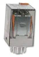
Illustrative purposes only

60.13.9.048.0040
General Purpose Relay, 60 Series, Power, 3PDT, 48 VDC, 10 A
⚠️ Reference pricing provided. In case of supply shortages, we will connect you with our trusted procurement partners to ensure your project's continuity.
- Manufacturer: FINDER
- Product type: Power Relays
- Contact Configuration:3PDT; Coil Voltage:48VDC; Contact Current:10A; Product Range:60 Series; Relay Mounting:Socket; Coil Type:-; Contact Voltage VAC:250VAC; Relay Terminals:Quick Connect; Conta
- SVHC: No SVHC (04-Feb-2026)
- Coil Type: -
- Coil Voltage: 48VDC
- Product Range: 60 Series
- Relay Mounting: Socket
- Coil Resistance: 1.772kohm
- Contact Current: 10A
- Relay Terminals: Quick Connect
- Contact Material: Silver Nickel
- Contact Voltage VAC: 250VAC
- Contact Voltage VDC: -
- Approvals & Standards: CE, CSA, UL, VDE
- Contact Configuration: 3PDT
| Delivery and price | |
|---|---|
| Units per pack | 50 |
| Price | 14.1 € |
| Current stock | 10+ |
| Lead time | 30 days |
Datasheet

**60 SERIES**

**A**

## **Plug-in mount**

**==> picture [26 x 7] intentionally omitted <==**

**----- Start of picture text -----**<br>
60.12<br>**----- End of picture text -----**<br>


**==> picture [26 x 7] intentionally omitted <==**

**----- Start of picture text -----**<br>
60.13<br>**----- End of picture text -----**<br>


## **10 A General purpose relay**

- 2 & 3 pole changeover contacts

- Cadmium Free contacts (preferred version)

- AC coils & DC coils

- UL Listing (certain relay/socket combinations)

- Contact material options

- Lockable test button with mechanical flag indicator (preferred version)

- 90 series sockets

- Coil EMC suppression

- Timer accessories 86 series

- European Patent

- 2 pole, 10 A power contacts

- 8 pin plug-in

- 3 pole, 10 A power contacts

- 11 pin plug-in

## _For UL ratings see:_

_“General technical information” page_ V

|**Contact specification**<br>Contact configuration|||2 CO (DPDT)||||||3 CO (3PDT)|
|---|---|---|---|---|---|---|---|---|---|
|Rated current/Maximum peak current<br>A|||10/20||||||10/20|
|Rated voltage/<br>Maximum switchingvoltage|V AC||250/400||||||250/400|
|Rated load AC1|VA||2500||||||2500|
|Rated load AC15 (230 V AC)|VA||500||||||500|
|Single phase motor rating (230 V AC)|Single phase motor rating (230 V AC)<br>kW||0.37||||||0.37|
|Breaking capacity DC1: 30/110/220 V<br>A|||10/0.4/0.15||||||10/0.4/0.15|
|Minimum switching load|mW (V/mA)||500 (10/5)||||||500 (10/5)|
|Standard contact material<br>**Coil specification**|||AgNi||||||AgNi|
|Nominal voltage (UN)|V AC (50/60 Hz)||6 - 12 - 24 - 48 - 60 - 110 - 120 - 230 - 240 - 400|6 - 12 - 24 - 48 - 60 - 110 - 120 - 230 - 240 - 400|6 - 12 - 24 - 48 - 60 - 110 - 120 - 230 - 240 - 400||||6 - 12 - 24 - 48 - 60 - 110 - 120 - 230 - 240 - 400|
||V DC|||6 - 12 - 24 - 48 - 60 - 110 -125 - 220|6 - 12 - 24 - 48 - 60 - 110 -125 - 220|||||
|Rated power AC/DC|VA (50 Hz)/W||2.2/1.3||||||2.2/1.3|
|Operating range|AC||(0.8…1.1)UN||||||(0.8…1.1)UN|
||DC||(0.8…1.1)UN||||||(0.8…1.1)UN|
|Holding voltage|AC/DC|0.8 UN/ 0.5 UN|||||||0.8 UN/ 0.5 UN|
|Must drop-out voltage<br>**Technical data**|AC/DC|0.2 UN/ 0.1 UN|||||||0.2 UN/ 0.1 UN|
|Mechanical life AC/DC|cycles|20 · 106/ 50 · 106|||||||20 · 106/ 50 · 106|
|Electrical life at rated load AC1|cycles||200 · 103||||||200 · 103|
|Operate/release time|ms||11/4||||||11/4|
|Insulation between coil||||||||||
|and contacts(1.2/50μs)<br>Dielectric strength<br>between open contacts<br>Ambient temperature range<br>Environmental protection|kV<br>V AC<br>°C|CE|4<br>1000<br>–40…+70<br>RT I<br>@|Hl|©@|@|||3.6<br>1000<br>–40…+70<br>RT I<br>RINAcAXus|
|**Approvals**(according to type)||CE|@|Hl|©@|@|||RINAcAXus|


**1**

**60 SERIES**

## **Plug-in mount - 6 A Bifurcated contacts for low level switching**

## **60.12 - 5200**

## **60.13 - 5200**

- 2 & 3 pole changeover contacts

**A**

- Cadmium Free contacts

- (Gold plated Silver Nickel)

- AC coils & DC coils

- Lockable test button with mechanical flag indicator (preferred version)

- 90 series sockets

- Coil EMC suppression

- Timer accessories 86 series

- European Patent

- 2 pole, 6 A bifurcated contacts

- 8 pin plug-in

- 3 pole, 6 A bifurcated contacts

- 11 pin plug-in

## _For UL ratings see:_

_“General technical information” page_ V

## **Contact specification**

|Contact configuration|||2 CO (DPDT)|||||3 CO (3PDT)||
|---|---|---|---|---|---|---|---|---|---|
|Rated current/Maximum peak current<br>A|||6/10|||||6/10||
|Rated voltage/<br>Maximum switchingvoltage|V AC||250/400|||||250/400||
|Rated load AC1|VA||1500|||||1500||
|Rated load AC15 (230 V AC)|VA||250|||||250||
|Single phase motor rating (230 V AC)|Single phase motor rating (230 V AC)<br>kW||0.185|||||0.185||
|Breaking capacity DC1: 30/110/220 V<br>A|||6/0.3/0.12|||||6/0.3/0.12||
|Minimum switching load|mW (V/mA)||50 (5/5)|||||50 (5/5)||
|Standard contact material<br>**Coil specification**||AgNi + Au bifurcated contacts||||||AgNi + Au bifurcated contacts||
|Nominal voltage (UN)|V AC (50/60 Hz)||6 - 12 - 24 - 48 - 60 - 110 - 120 - 230 - 240 - 400|6 - 12 - 24 - 48 - 60 - 110 - 120 - 230 - 240 - 400||||6 - 12 - 24 - 48 - 60 - 110 - 120 - 230 - 240 - 400||
||V DC|||6 - 12 - 24 - 48 - 60 - 110 -125 - 220||||||
|Rated power AC/DC|VA (50 Hz)/W||2.2/1.3|||||2.2/1.3||
|Operating range|AC||(0.8…1.1)UN|||||(0.8…1.1)UN||
||DC||(0.8…1.1)UN|||||(0.8…1.1)UN||
|Holding voltage|AC/DC|0.8 UN/ 0.5 UN||||||0.8 UN/ 0.5 UN||
|Must drop-out voltage<br>**Technical data**|AC/DC|0.2 UN/ 0.1 UN||||||0.2 UN/ 0.1 UN||
|Mechanical life AC/DC|cycles|20 · 106/ 50 · 106||||||20 · 106/ 50 · 106||
|Electrical life at rated load AC1|cycles||250 · 103|||||250 · 103||
|Operate/release time|ms||11/4|||||11/4||
|Insulation between coil||||||||||
|and contacts(1.2/50μs)<br>Dielectric strength<br>between open contacts<br>Ambient temperature range<br>Environmental protection<br>**Approvals**(according to type)|kV<br>V AC<br>°C|4<br>3.6<br>1000<br>1000<br>–40…+70<br>–40…+70<br>RT I<br>RT I<br>~~a~~<br>CE<br>@ HH & @<br>RINA cAXs|||||||IV-2014, www.findernet.com|


**2**

**60 SERIES**

**A**

## **Flange mount - General purpose relay 10 A**

**==> picture [26 x 7] intentionally omitted <==**

**----- Start of picture text -----**<br>
60.62<br>**----- End of picture text -----**<br>


**==> picture [26 x 7] intentionally omitted <==**

**----- Start of picture text -----**<br>
60.63<br>**----- End of picture text -----**<br>


- Faston 187, (4.8 x 0.8 mm)

- 2 & 3 pole changeover contacts

- AC coils & DC coils

- Cadmium Free contacts

- Contacts material options

• 2 pole, 10 A power contacts

- Flange mount/Faston 187

- 3 pole, 10 A power contacts

- Flange mount/Faston 187

||_For ULratings see:_||7~~.~~1|18|7~~.~~1<br>11|9596244|9596244|9596244|9596244||||7.1|18|7.1<br>11|9596244|
|---|---|---|---|---|---|---|---|---|---|---|---|---|---|---|---|---|
||_“General technical information” page_V||||||||||||||||
||**Contact specification**<br>Contact configuration|||2 CO (DPDT)||||||||||3 CO (3PDT)|||
||Rated current/Maximum peak current<br>A||||10/20||||||||||10/20||
||Rated voltage/<br>Maximum switchingvoltage|V AC|||250/400||||||||||250/400||
||Rated load AC1|VA|||2500||||||||||2500||
||Rated load AC15 (230 V AC)|VA|||500||||||||||500||
||Single phase motor rating (230 V AC)|Single phase motor rating (230 V AC)<br>kW|||0.37||||||||||0.37||
||Breaking capacity DC1: 30/110/220 V<br>A|||10/0.4/0.15||||||||||10/0.4/0.15|||
||Minimum switching load|mW (V/mA)|||500 (10/5)||||||||||500 (10/5)||
||Standard contact material<br>**Coil specification**||||AgNi||||||||||AgNi||
||Nominal voltage (UN)|V AC (50/60 Hz)|||6 - 12 - 24 - 48 - 60 - 110 - 120 - 230 - 240 - 400|6 - 12 - 24 - 48 - 60 - 110 - 120 - 230 - 240 - 400|||||||6 - 12 - 24 - 48 - 60 - 110 - 120 - 230 - 240 - 400|6 - 12 - 24 - 48 - 60 - 110 - 120 - 230 - 240 - 400|||
|||V DC|||||6 - 12 - 24 - 48 - 60 - 110 -125 - 220||||||||||
||Rated power AC/DC|VA (50 Hz)/W|||2.2/1.3||||||||||2.2/1.3||
||Operating range|AC||(0.8…1.1)UN||||||||||(0.8…1.1)UN|||
|||DC||(0.8…1.1)UN||||||||||(0.8…1.1)UN|||
||Holding voltage|AC/DC||0.8 UN/ 0.5 UN||||||||||0.8 UN/ 0.5 UN|||
||Must drop-out voltage<br>**Technical data**|AC/DC||0.2 UN/ 0.1 UN||||||||||0.2 UN/ 0.1 UN|||
||Mechanical life AC/DC|cycles||20 · 106/ 50 · 106||||||||||20 · 106/ 50 · 106|||
||Electrical life at rated load AC1|cycles|||200 · 103||||||||||200 · 103||
||Operate/release time|ms|||11/4||||||||||11/4||
||Insulation between coil||||||||||||||||
|IV-2014, www.findernet.com|and contacts(1.2/50μs)<br>Dielectric strength<br>between open contacts<br>Ambient temperature range<br>Environmental protection<br>**Approvals**(according to type)|kV<br>V AC<br>°C|C€||4<br>1000<br>–40…+70<br>RT I<br>@||Hl||& @||||RINA||3.6<br>1000<br>–40…+70<br>RT I<br> cAYs||


**3**

**60 SERIES**

## **Ordering information**

Example:  60 series plug-in relay, 3 CO (3PDT), 12 V DC coil, test button and mechanical indicator.

**A**

**A B C D 0 0 4 0**

## **6 0 . 1 3 . 9 . 0 1 2 . 0**

## **D: Special versions**

**A: Contact material**

## **Series**

   - 0 = Standard

- 0 = Standard

## **Type**

   - 5 = AgNi + Au

- 1 =  8/11 pin plug-in

## **C: Options**

## **B: Contact circuit**

- 6 =  Faston 187 (4.8 x 0.8 mm) with flange mount

   - 0 =  None

   - 2 =  Mechanical indicator

- 0 = CO (nPDT)

- 2 =  Bifurcated contacts

- 3 =  LED (AC)

## **No. of poles**

      - 4 =  Lockable test button + mechanical indicator

   - 60.12/13 - 6 A only

- 2 = 2 pole

- 3 = 3 pole

- 5* =  Lockable test button + LED (AC)

## **Coil version**

- 54* =  Lockable test button + LED (AC) + mechanical indicator

4 = Current sensing (60.12/13 only)

- 8 = AC (50/60 Hz)

- 6* =  LED + diode (DC, polarity positive to pin 2)

9 = DC

## **Coil voltage**

- 7* =  Lockable test button + LED + diode

See coil specifications

   - (DC, polarity positive to pin 2)

- 74* =  Lockable test button + LED +

   - diode (DC, polarity positive to pin 2) + mechanical indicator

- Options not available for 220 V DC and 400 V AC versions.

**Selecting features and options: only combinations in the same row are possible.** Preferred selections for best availability are shown in **bold** . **Type Coil version A B C D** ~~ae ee es~~ 60.12/13 AC **0 0** 0 - 2 - 3 - **4** - 5 **0** ~~ee ee es ns~~ AC 0 0 54 / ~~eeesns~~ AC 5 0 - 2 0 - 2 - 3 - 4 - 5 0 ~~es~~ AC 5 0 - 2 54 / DC **0 0** 0 - 2 - **4** - 6 - 7 **0** DC 0 0 74 / ~~eees~~ DC 5 0 - 2 0 - 2 - 4 - 6 - 7 0 ~~eeeses~~ DC 5 0 - 2 74 / ~~ee ns §=====ee~~ current sensing ~~es~~ 0 ~~ee es~~ 0 4 0 ~~rs~~ 60.62/63 AC-DC **0** - 5 ~~nn~~ **0 0 0**

**Descriptions: Options and Special versions**

**C: Option 3, 5, 54 C: Option 6, 7, 74** LED (AC) LED + diode (DC, polarity positive to pin 2) **Lockable test button and mechanical flag indicator (0040, 0050, 0054, 0070, 0074) 1 3** The dual-purpose Finder test button can be used in two ways: Case 1) The plastic pip (located directly above the test button) remains intact. In this case, when the } | a test button is pushed, the contacts operate. When the test button is released the contacts return to ZB their former state. Case 2) The plastic pip is broken-off (using an appropriate cutting tool). In this case, (in addition to the above function), when the test button is pushed and rotated, the contacts are latched in the as y ErEe operating state, and remain so until the test button is rotated back to its former position. **2** In both cases ensure that the test button actuation is swift and decisive.

**4**

**60 SERIES**

## **Technical data**

**==> picture [512 x 320] intentionally omitted <==**

**----- Start of picture text -----**<br>
Insulation according to EN 61810-1 2 pole 3 pole<br>Nominal voltage of supply system   V AC 230/400 230/400<br>Rated insulation voltage   V AC 250 400 250 400<br>Pollution degree 3 2 3 2<br>Insulation between coil and contact set<br>Type of insulation Basic Basic<br>Overvoltage category III III<br>Rated impulse voltage   kV (1.2/50 μs) 4 3.6<br>Dielectric strength   V AC 2000 2000<br>Insulation between adjacent contacts<br>Type of insulation Basic Basic<br>Overvoltage category III III<br>Rated impulse voltage   kV (1.2/50 μs) 4 3.6<br>Dielectric strength   V AC 2000 2000<br>Insulation between open contacts<br>Type of disconnection Micro-disconnection Micro-disconnection<br>Dielectric strength   V AC/kV (1.2/50 μs) 1000/1.5 1000/1.5<br>Conducted disturbance immunity<br>Burst (5…50)ns, 5 kHz, on A1 - A2 EN 61000-4-4 level 4 (4 kV)<br>Surge (1.2/50 μs) on A1 - A2 (differential mode) EN 61000-4-5 level 4 (4 kV)<br>Other data<br>Bounce time: NO/NC   ms 1/4<br>Vibration resistance (5…55)Hz: NO/NC   g 22/22<br>Shock resistance   g 20<br>Power lost to the environment without contact current   W 1.3 1.3<br>with rated current   W 2.7 (60.12, 60.62) 3.4 (60.13, 60.63)<br>**----- End of picture text -----**<br>


**A**

## **Contact specification**

## **F 60 - Electrical life (AC) v contact current**

**==> picture [216 x 109] intentionally omitted <==**

**----- Start of picture text -----**<br>
Resistive load - cosφ = 1<br>Inductive load - cosφ = 0.4<br>Cycles<br>**----- End of picture text -----**<br>


## **H 60 - Maximum DC1 breaking capacity**

**==> picture [217 x 126] intentionally omitted <==**

**----- Start of picture text -----**<br>
contacts in series<br>DC voltage (V)<br>DC breaking current (A)<br>**----- End of picture text -----**<br>


- When switching a resistive load (DC1) having voltage and current values under the curve, an electrical life of ≥ 100 · 10[3] can be expected.

- In the case of DC13 loads, the connection of a diode in parallel with the load will permit a similar electrical life as for a DC1 load. Note: the release time for the load will be increased.

## **Coil specifications**

|Nominal<br>voltage<br>UN|Coil code|Operating range<br>Umin<br>Umax|Operating range<br>Umin<br>Umax|Resistance<br>R|
|---|---|---|---|---|
|V||V|V|Ω|
|6|**9**.006|4.8|6.6|28|
|12|**9**.012|9.6|13.2|110|
|24|**9**.024|19.2|26.4|445|
|48|**9**.048|38.4|52.8|1770|
|60|**9**.060|48|66|2760|
|110|**9**.110|88|121|9420|
|125|**9**.125|100|138|12000|
|220|**9**.220|176|242|37300|


## **AC coil data**

**==> picture [253 x 50] intentionally omitted <==**

**----- Start of picture text -----**<br>
Nominal  Coil code Operating range Resistance Rated coil<br>voltage absorption<br>UN Umin Umax R I at UN (50 Hz)<br>V V V Ω mA<br>**----- End of picture text -----**<br>


||**ta**|||||
|---|---|---|---|---|---|
||Coil code<br>|Operating range<br>Umin<br>Umax<br>V<br>V<br><br>||Resistance<br>R<br>Ω<br>|Rated coil<br>absorption<br>Iat UN(50 Hz)<br>mA<br>|
|6<br>12<br>24<br>48<br>60<br>110<br>120<br>230<br>240<br>400|**8**.006|4.8|6.6|4.6|367|
||**8**.012|9.6|13.2|19|183|
||**8**.024|19.2|26.4|74|90|
||**8**.048|38.4|52.8|290|47|
||**8**.060|48|66|450|37|
||**8**.110|88|121|1600|20|
||**8**.120|96|132|1940|18.6|
||**8**.230|184|253|7250|10.5|
||**8**.240|192|264|8500|9.2|
||**8**.400|320|440|19800|6|


**5**

**60 SERIES**

## **Coil specifications**

## **R 60 - DC coil operating range v ambient temperature**

## **R 60 - AC coil operating range v ambient temperature**

**A**

**1 -** Max. permitted coil voltage.

**2 -** Min. pick-up voltage with coil at ambient temperature.

**1 -** Max. permitted coil voltage.

**2 -** Min. pick-up voltage with coil at ambient temperature.

## **Current sensing version**

|Coil code<br>4202<br>~~ee~~|Imin(A)<br>1.7<br>~~ee~~<br>~~ee~~|IN(A)<br>2.0<br>~~ee~~<br>~~ee~~|Imax(A)<br>2.4<br>~~ee~~<br>~~ee~~|R (Ω)<br>0.15<br>~~ee~~|
|---|---|---|---|---|
|4182<br>~~ee~~<br>~~SO~~<br>~~J~~|1.5<br>~~ee~~<br>~~ee ~~<br>~~SO~~<br>|1.8<br>~~ee~~<br> ~~ee ~~<br>~~SO~~<br>|2.2<br>~~ee~~<br> ~~ee~~<br>~~SO~~<br>|0.19<br>~~ee~~<br>~~SO~~<br>|
|4162<br>~~SO~~<br>~~J~~|1.4<br>~~SO~~<br>|1.6<br>~~SO~~<br>|1.9<br>~~SO~~<br>|0.24<br>~~SO~~<br>|
|4142<br>~~J~~|1.2<br>|1.4<br>|1.7<br>|0.31<br>|
|4122<br>~~JCa~~<br>~~SO~~|1.0<br>~~Ca~~<br>~~SO~~|1.2<br>~~Ca~~<br>~~SO~~|1.4<br>~~Ca~~<br>~~SO~~|0.42<br>~~Ca~~<br>~~SO~~|
|4102<br>~~SO~~<br>~~SC~~|0.85<br>~~SO~~<br>~~SC~~|1.0<br>~~SO~~<br>~~SC~~|1.2<br>~~SO~~<br>~~SC~~|0.61<br>~~SO~~<br>~~SC~~|
|4092<br>~~SO~~<br>~~SC~~|0.8<br>~~SO~~<br>~~SC~~|0.9<br>~~SO~~<br>~~SC~~|1.1<br>~~SO~~<br>~~SC~~|0.75<br>~~SO~~<br>~~SC~~|
|4062<br>~~SC~~<br>~~SO~~|0.5<br>~~SC~~<br>~~SO~~|0.6<br>~~SC~~<br>~~SO~~|0.7<br>~~SC~~<br>~~SO~~|1.70<br>~~SC~~<br>~~SO~~|
|4032<br>~~SO~~<br>~~SO~~|0.25<br>~~SO~~<br>~~SO~~<br>~~C~~|0.3<br>~~SO~~<br>~~SO~~|0.4<br>~~SO~~<br>~~SO~~|6.70<br>~~SO~~<br>~~SO~~|
|4012<br>~~SO~~<br>~~eS~~|0.085<br>~~SO~~<br>~~eS~~<br>~~C~~|0.1<br>~~SO~~<br>~~eS~~|0.15<br>~~SO~~<br>~~eS~~|61<br>~~SO~~<br>~~eS~~|


Typical application with current sensing relays. An open circuit filiment of lamp L1 is detected by the current sensing relay coil (K1) which causes the back-up safety lamp L2 to be energised, and indication of failure at the control panel via lamp S1.

Example: navigation light. L1 = Light L2 = Safety light S1= Control light K1 = Relay

## **Current sensing AC coil data**

|Coil code<br>4251|Imin(A)<br>2.1|IN(A)<br>2.5|Imax(A)<br>3.0|R (Ω)<br>0.05|
|---|---|---|---|---|
|4181<br>~~SO~~|1.5<br>~~SO~~|1.8<br>~~SO~~|2.2<br>~~SO~~|0.10<br>~~SO~~|
|4161<br>~~SC~~|1.4<br>~~SC~~|1.6<br>~~SC~~|1.9<br>~~SC~~|0.12<br>~~SC~~|
|4121<br>~~SO~~|1.0<br>~~SO~~|1.2<br>~~SO~~|1.4<br>~~SO~~|0.22<br>~~SO~~|
|4101<br>~~SO~~<br>~~SO~~|0.85<br>~~SO~~<br>~~SO~~|1.0<br>~~SO~~<br>~~SO~~|1.2<br>~~SO~~<br>~~SO~~|0.32<br>~~SO~~<br>~~SO~~|
|4051<br>~~SO~~<br>~~SO~~|0.42<br>~~SO~~<br>~~SO~~|0.5<br>~~SO~~<br>~~SO~~|0.6<br>~~SO~~<br>~~SO~~|1.28<br>~~SO~~<br>~~SO~~|
|4041<br>~~Oa~~|0.34<br>~~Oa~~|0.4<br>~~Oa~~|0.5<br>~~Oa~~|2.00<br>~~Oa~~|
|4031<br>~~SO~~|0.25<br>~~SO~~|0.3<br>~~SO~~|0.4<br>~~SO~~|3.57<br>~~SO~~|
|4021<br>~~SO~~|0.17<br>~~SO~~|0.2<br>~~SO~~|0.25<br>~~SO~~|8.0<br>~~SO~~|
|4011<br>~~SO~~<br>~~SO~~|0.085<br>~~SO~~<br>~~SO~~|0.1<br>~~SO~~<br>~~SO~~|0.15<br>~~SO~~<br>~~SO~~|32.1<br>~~SO~~<br>~~SO~~|


Other types of current sensing relays are available on request.

## **Accessories**

**Sheet of marker tags** for relay types 60.12 and 60.13, plastic, 72 tags, 6 x 12 mm 060.72

**060.72**

**6**

**60**

**SERIES**

**Module Socket Relay Description Mounting Accessories 99.02 90.02** 60.12 **Screw terminal (Box clamp) socket** Panel or 35 mm rail -  Coil indication and EMC ~~a~~ **90.03** 60.13 Double A1 terminal (EN 60715) mount suppression modules -  Jumper link **A** -  Timer modules -  Metal retaining clip **90.03** See page 8 ~~eo~~ **Module Socket Relay Description Mounting Accessories** ~~—————~~ **99.01 90.20** 60.12 **Screw terminal (Box clamp) socket** Panel or 35 mm rail -  Coil indication and EMC **90.21** 60.13 (EN 60715) mount suppression modules -  Metal retaining clip er **90.21** See page 9 **Module Socket Relay Description Mounting Accessories — 90.82.3** 60.12 **Screw terminal (Box clamp) socket** Panel or 35 mm rail -  Metal retaining clip **— 90.83.3** 60.13 (EN 60715) mount g ~~e~~ **90.83.3** ~~——~~ See page 10 **Module Socket Relay Description Mounting Accessories — 90.22** 60.12 **Screw terminal (Box clamp) socket** Panel or 35 mm rail -  Metal retaining clip **— 90.23** 60.13 (EN 60715) mount ~~2~~ **90.23** See page 10 **Module Socket Relay Description Mounting Accessories — 90.26** 60.12 **Screw terminal (Plate clamp) socket** Panel or 35 mm rail -  Metal retaining clip **— 90.27** 60.13 (EN 60715) mount oe ~~——————~~ **90.26** See page 11 **Module Socket Relay Description Mounting Accessories — 90.12** 60.12 **Flange mount solder socket** M3 screw fixing — **— 90.13** 60.13 **90.12** See page 11 **Module Socket Relay Description Mounting Accessories — 90.14** 60.12 **PCB socket** PCB — == **90.15 — 90.14.1** 60.12 See page 12 **— 90.15** 60.13 **— 90.15.1** 60.13

**7**

**60 SERIES**

**A**

**==> picture [483 x 235] intentionally omitted <==**

**----- Start of picture text -----**<br>
||||||
|---|---|---|---|---|
|Screw terminal (Box clamp) socket|90.02|90.02.0|90.03|90.03.0|
|panel or 35 mm rail (EN 60715) mount|Blue|Black|Blue|Black|
|For relay type|60.12|60.13|
|Accessories|
|Metal retaining clip|090.33|
|6-way|jumper link|090.06|
|90.03|
|Identification tag|090.00.2|
|Approvals|
|(according to type):|Modules (see table below)|99.02|
|CEG|HH|&|Timer modules (see table below)|86.00, 86.30|
|Technical data|
|@|Adis|Rated values|10 A - 250 V|
|Dielectric strength|2 kV AC|
|eM) us|Certain relay/socket combinations|Protection category|IP 20|
|Ambient temperature|°C|–40…+70|
|©|Screw torque|Nm|0.6|
|Wire strip length|mm|10|
|Max. wire size for 90.02 and 90.03 sockets|solid wire|stranded wire|
|mm|[2]|1 x 6 / 2 x 2.5|1 x 4 / 2 x 2.5|
|AWG|1 x 10 / 2 x 14|1 x 12 / 2 x 14|

**----- End of picture text -----**<br>


**==> picture [518 x 366] intentionally omitted <==**

**----- Start of picture text -----**<br>
||||||||||||||
|---|---|---|---|---|---|---|---|---|---|---|---|---|
|6-way jumper link|for 90.02 and 90.03 sockets|090.06 (blue)|090.06.0 (black)|
|Rated values|10 A - 250 V|
|Approvals|
|(according to type):|
|090.06|i|@|FAL|SANs|u|
|0|a|49.5|15|23|15|23|15|49.5|[|12.8|||||
|86 series timer modules|
|Multi-voltage: (12…240)V AC/DC;|
|Multi-functions: AI, DI, SW, BE, CE, DE, EE, FE;|(0.05 s…100 h)|86.00.0.240.0000|
|86.00|(12…24)V AC/DC; Bi-function: AI, DI; (0.05 s…100 h)|86.30.0.024.0000|
|(110…125)V AC; Bi-function: AI, DI; (0.05 s…100 h)|86.30.8.120.0000|
|a|«ZS|
|(230…240)V AC; Bi-function: AI, DI; (0.05 s…100 h)|86.30.8.240.0000|
|Approvals (according to type):|
|ee|CE|EAL|&|Ais|
|a|99.02 coil indication and EMC suppression modules|for 90.02 and 90.03 sockets|
|86.30|As|Diode (+A1, standard polarity)|(6…220)V DC|99.02.3.000.00|
|LED|(6…24)V DC/AC|99.02.0.024.59|
|LED|(28…60)V DC/AC|99.02.0.060.59|
|=|LED|(110…240)V DC/AC|99.02.0.230.59|
|LED + Diode (+A1, standard polarity)|(6…24)V DC|99.02.9.024.99|
|coe|
|Lagan|LED + Diode (+A1, standard polarity)|(28…60)V DC|99.02.9.060.99|
|99.02|Da.|LED + Diode (+A1, standard polarity)|(110…220)V DC|99.02.9.220.99|
|Approvals|LED + Varistor|(6…24)V DC/AC|99.02.0.024.98|
|(according to type):|LED + Varistor|(28…60)V DC/AC|99.02.0.060.98|
|FAL|&|As|LED + Varistor|(110…240)V DC/AC|99.02.0.230.98|
|RC circuit|(6…24)V DC/AC|99.02.0.024.09|
|DC Modules with non-|RC circuit|(28…60)V DC/AC|99.02.0.060.09|
|standard polarity (+A2) on|RC circuit|(110…240)V DC/AC|99.02.0.230.09|
|request.|Residual current by-pass|(110…240)V AC|99.02.8.230.07|
|E|

**----- End of picture text -----**<br>


**8**

**60 SERIES**

**90.21** Approvals (according to type):

|**Screw terminal (Box clamp) socket**<br>panel or 35 mm rail (EN 60715) mount<br>For relay type<br>**Accessories**<br>Metal retaining clip<br>pplied with socket -packagingcode SMA)|**90.20**<br>**Blue**<br>**90.20.0**<br>**Black**<br>**90.21**<br>**Blue**<br>**90.21.0**<br>**Black**<br>60.12<br>60.13<br>090.33|**90.20**<br>**Blue**<br>**90.20.0**<br>**Black**<br>**90.21**<br>**Blue**<br>**90.21.0**<br>**Black**<br>60.12<br>60.13<br>090.33|
|---|---|---|
|Modules (see table below)<br>**Technical data**<br>Rated values|99.01<br>10 A - 250 V||
|Dielectric strength|2 kV AC||
|Protection category|IP 20||
|Ambient temperature<br>Screw torque|°C –40…+70||
|Screw torque<br>Nm|Nm 0.5||
|Wire striplength<br>mm|mm 10||
|Max. wire size for 90.20 and 90.21 sockets<br>mm<br>AWG|solid wire<br>stranded wire<br>mm2<br>1 x 6 / 2 x 2.5<br>1 x 6 / 2 x 2.5|stranded wire|
|||1 x 6 / 2 x 2.5|
||AWG<br>1 x 10 / 2 x 14<br>1 x 10 / 2 x 14|1 x 10 / 2 x 14|


**A**

**==> picture [191 x 6] intentionally omitted <==**

**----- Start of picture text -----**<br>
90.20 90.21<br>**----- End of picture text -----**<br>


## **99.01 coil indication and EMC suppression modules** for 90.20 and 90.21 sockets

**99.01**

Approvals

(according to type):

*  Modules in Black housing are available on request.

Green LED is standard. Red LED available on request.

||**Blue***|
|---|---|
|Diode (+A1, standard polarity)<br>(6…220)V DC|99.01.3.000.00|
|Diode (+A2, non-standard polarity)<br>(6…220)V DC|99.01.2.000.00|
|(6…24)V DC/AC|99.01.0.024.59|
|(28…60)V DC/AC|99.01.0.060.59|
|(110…240)V DC/AC|99.01.0.230.59|
|LED + Diode (+A1, standard polarity)<br>(6…24)V DC|99.01.9.024.99|
|LED + Diode (+A1, standard polarity)<br>(28…60)V DC|99.01.9.060.99|
|LED + Diode (+A1, standard polarity)<br>(110…220)V DC|99.01.9.220.99|
|LED + Diode (+A2, non-standard polarity)<br>(6…24)V DC|99.01.9.024.79|
|LED + Diode (+A2, non-standard polarity)<br>(28…60)V DC|99.01.9.060.79|
|LED + Diode (+A2, non-standard polarity)<br>(110…220)V DC|99.01.9.220.79|
|LED + Varistor<br>(6…24)V DC/AC|99.01.0.024.98|
|LED + Varistor<br>(28…60)V DC/AC|99.01.0.060.98|
|LED + Varistor<br>(110…240)V DC/AC|99.01.0.230.98|
|RC circuit<br>(6…24)V DC/AC|99.01.0.024.09|
|RC circuit<br>(28…60)V DC/AC|99.01.0.060.09|
|RC circuit<br>(110…240)V DC/AC|99.01.0.230.09|
|Residual current by-pass<br>(110…240)V AC|99.01.8.230.07|


**9**

**60 SERIES**

**==> picture [503 x 545] intentionally omitted <==**

**----- Start of picture text -----**<br>
|||||||||||||||||
|---|---|---|---|---|---|---|---|---|---|---|---|---|---|---|---|
|Screw terminal (Box clamp) socket|90.82.3|90.82.30|90.83.3|90.83.30|
|panel or 35 mm rail (EN 60715) mount|Blue|Black|Blue|Black|
|For relay type|60.12|60.13|
|A|Accessories|
|Metal retaining clip|090.33|
|Technical data|
|90.83.3|Rated values|10 A - 250 V|
|Approvals|
|Dielectric strength|2 kV AC|
|(according to type):|
|Protection category|IP 20|
|CEG HA|&®|OO|Ambient temperature|°C|–40…+70|
|Mis|©|Screw torque|Nm|0.8|
|Max. wire size for 90.82.3 and 90.83.3 sockets|solid wire|stranded wire|
|mm|[2]|1 x 6 / 2 x 4|1 x 6 / 2 x 4|
|AWG|1 x 10 / 2 x 14|1 x 10 / 2 x 14|
|NO|NC|NC|NO|NC|NO|com|NC|a|
|1|@®Q|©Pal|i|5|i|
|NC|
|3|OO.||Ie3|.|2|I|l|000,||Io3.2|
|l|Or|Ogal|Or)|Oda|on|i|c|
|O|D5|om|©|HOS|OM}|oO|SY|
|a|9|
|so|||cr|©||],|Og?|q|n|
|I|I|I|||
|COILCOM|COM COIL|||as _||COI|L|COMCOM|C|OIL|||m|e|s|||ol|——r7|
|38|38|
|90.82.3|90.83.3|
|Screw terminal (Box clamp) socket|90.22|90.23|
|panel or 35 mm rail (EN 60715) mount|Blue|Blue|
|For relay type|60.12|60.13|
|Accessories|
|Metal retaining clip|
|(supplied with socket - packaging code SMA)|090.33|
|90.23|Technical data|
|Approvals|Rated values|10 A - 250 V|
|(according to type):|Dielectric strength|2 kV AC|
|CEG|HA|S&S|Protection category|IP 20|
|®|Ambient temperature|°C|–40…+70|
|CALs|8|Screw torque|Nm|0.5|
|Wire strip length|mm|7|
|Max. wire size for 90.22 and 90.23 sockets|solid wire|stranded wire|
|mm|[2]|1 x 6 / 2 x 2.5|1 x 6 / 2 x 2.5|
|AWG|1 x 10 / 2 x 14|1 x 10 / 2 x 14|

**----- End of picture text -----**<br>


**==> picture [241 x 6] intentionally omitted <==**

**----- Start of picture text -----**<br>
90.22 90.23<br>**----- End of picture text -----**<br>


**10**

**60 SERIES**

**Screw terminal (Box clamp) socket 90.26 90.26.0 90.27 90.27.0** panel or 35 mm rail (EN 60715) mount **Blue Black Blue Black** For relay type 60.12 60.13 **Accessories** Metal retaining clip (supplied with socket - packaging code SMA) 090.33 **90.26 Technical data** Approvals (according to type): Rated values 10 A - 250 V CEG EA & Dielectric strength 2 kV AC Protection category IP 20 @ Adis® Ambient temperature °C –40…+70 Screw torque Nm 0.8 Wire strip length mm 10 Max. wire size for 90.26 and 90.27 sockets solid wire stranded wire mm[2] 1 x 4 / 2 x 2.5 1 x 4 / 2 x 2.5 AWG 1 x 12 / 2 x 14 1 x 12 / 2 x 14 NO NC NC NO 33 20 NC NOCOM NC 35 ~~hal~~ Las [oxe) ~~¢~~ hag | Goug Ee O. > BeOcG=h 4A | a ~~OA~~ o8 DSOSeee ~~EH© S~~ 68 |=| w ite} ~~a~~ A ~~S~~ o 6 ARIE Selfio_ | ~~No~~ ty le ~~lefe~~ le} “47 COILCOMCOMCOIL ~~La~~ 23 ~~, COIL COM~~ COM COIL ~~43~~ 31 90.26 90.27

**Flange mount solder socket** mount with M3 screw **90.12 (black) 90.13 (black)** For relay type 60.12 60.13 **Technical data** Rated values 10 A - 250 V Dielectric strength 2 kV AC Ambient temperature °C –40…+70

**==> picture [75 x 30] intentionally omitted <==**

**----- Start of picture text -----**<br>
90.12<br>Approvals<br>(according to type):<br>**----- End of picture text -----**<br>


**==> picture [10 x 10] intentionally omitted <==**

**----- Start of picture text -----**<br>
A<br>**----- End of picture text -----**<br>


**==> picture [88 x 7] intentionally omitted <==**

**----- Start of picture text -----**<br>
90.12 90.13<br>**----- End of picture text -----**<br>


**11**

**60 SERIES**

**PCB socket Blue 90.14 (Ø 20.5 mm) 90.15 (Ø 22 mm) Blue 90.14.1 (Ø 17.5 mm) 90.15.1 (Ø 19 mm)** For relay type 60.12 60.13 **90.15 A Technical data** Approvals Rated values 10 A - 250 V (according to type): Dielectric strength 2 kV AC Ambient temperature °C –40…+70 CHSAls© ~~———~~ ‘s ~ ose eo ~~n f~~ 08, five, f ~~i~~ see ~~P~~ o ~~v~~ Cate7 02508 ~~a OO~~ OS 90.14 90.14.1 90.15 90.15.1 90.14 90.15 TailJolTARET 90.14 90.15

## **Packaging codes**

**How to code and identify retaining clip and packaging options for sockets.**

Example:

**9 0 . 2 1 S M A** ~~Eo~~ **A** Standard packaging **SM** Metal retaining clip **9 0 . 2 1** Without retaining clip ~~ee~~

**12**
Updated at June 7, 2026
About Novapart
Novapart is a B2B electronic component broker specialising in stock shortages and cost reduction. We source hard-to-find parts and identify compliant alternatives across a catalogue of 410,000+ components from 500+ manufacturers.
Learn more →Stock Shortage Specialist
When a component is unavailable, discontinued or has an unacceptable lead time, we tap into our network of vetted European and Asian distributors to source what you need — without compromising on quality or traceability.
Request a quote →Compliant Alternatives
We identify pin-to-pin, electrically equivalent substitutes that meet the same certifications (RoHS, AEC-Q100, REACH) as your original specification — validated against datasheets, not just part numbers. Often at a lower cost.
BOM Analysis service →