
Image not available
Illustrative purposes only

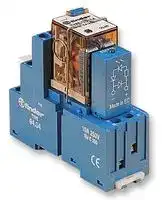
58.34.9.024.0050SMA
General Purpose Relay, 58 Series, Interface, 4PDT, 24 VDC, 7 A
⚠️ Reference pricing provided. In case of supply shortages, we will connect you with our trusted procurement partners to ensure your project's continuity.
- Manufacturer: FINDER
- Product type: Power Relays
- Contact Configuration:4PDT; Coil Voltage:24VDC; Contact Current:7A; Product Range:58 Series; Relay Mounting:DIN Rail; Coil Type:DC; Contact Voltage VAC:250VAC; Relay Terminals:Screw; Contact Volt
- SVHC: No SVHC (04-Feb-2026)
- Coil Type: DC
- Coil Voltage: 24VDC
- Product Range: 58 Series
- Relay Mounting: DIN Rail
- Coil Resistance: 600ohm
- Contact Current: 7A
- Relay Terminals: Screw
- Contact Material: Silver Nickel
- Contact Voltage VAC: 250V
- Contact Voltage VDC: 30V
- Contact Configuration: 4PDT
| Delivery and price | |
|---|---|
| Units per pack | 50 |
| Price | 18.65 € |
| Current stock | 50+ |
| Lead time | 30 days |
Datasheet

58 SЕRIES

## Relay interface modules 6 - 7 - 10 A

Control panels

Packaging machines Shipyards Textile machines Carousel warehouses Panels for electrical distribution Hoists and cranes

Wood-processing machines

Prices, features, specifications, capabilities, appearance and availability of our products and services are subject to change without notice. FINDER assumes no responsibility for the presence of possible errors or insufficient information in this document. In case of discrepancies between the printed and online versions, the latter prevails.

58 SERIES © ~~fi~~ nder pe

B

## **3 & 4 CO relay interface modules, 31 mm wide with Push-in terminals Ideal interface for PLC and electronic systems**

## **Type 58.P3**

- 3 CO 10 A

- Push-in terminals

## **Type 58.P4**

- 4 CO 7 A

- Push-in terminals

- AC coils or DC coils

- Supply status indication and EMC coil suppression module as standard

   - **58.P3 58.P4** = >»

   - • 3 CO 10 A • 4 CO 7 A • Push-in terminals • Push-in terminals

- Identification label

- Cadmium Free contacts

- UL Listing (certain relay/socket combinations)

- **Atex** compliant (Ex ec nC) option available

- **HazLoc** Class I Div. 2 Groups A, B, C, D - T5 option available

- • 35 mm rail (EN 60715) mounting

## 58.P3 / 58.P4

Push-in terminals

||For outline drawing see page 10|For outline drawing see page 10|Example: AC|||Example: DC|
|---|---|---|---|---|---|---|
||**Contact specification**<br>Contact configuration||3 CO (3PDT)|||4 CO (4PDT)|
||Rated current/Maximum peak current<br>A||10/20|||7/15|
||Rated voltage/<br>Maximum switchingvoltage|V AC|250/400|||250/250|
||Rated load AC1|VA|2500|||1750|
||Rated load AC15 (230 V AC)|VA|500|||350|
||Single phase motor rating (230 V AC)<br>kW||0.37|||0.125|
||Breaking capacity DC1: 24/110/220 V<br>A||10/0.5/0.25|||7/0.5/0.25|
||Minimum switching load|mW (V/mA)|300 (5/5)|||300 (5/5)|
||Standard contact material<br>**Coil specification**<br>Nominal voltage (UN)|V AC (50/60 Hz)|AgNi<br>12 - 24 - 48 - 110 - 120 - 230|||AgNi<br>12 - 24 - 48 - 110 - 120 - 230|
|||V DC|12 - 24 - 48 - 125|||12 - 24 - 48 - 125|
||Rated power AC/DC|VA (50 Hz)/W|1.5/1|||1.5/1|
||Operating range|AC|(0.8…1.1)UN|||(0.8…1.1)UN|
|||DC|(0.8…1.1)UN|||(0.8…1.1)UN|
||Holding voltage|AC/DC|0.8 UN/ 0.5 UN|||0.8 UN/ 0.5 UN|
||Must drop-out voltage<br>**Technical data**|AC/DC|0.2 UN/ 0.1 UN|||0.2 UN/ 0.1 UN|
||Mechanical life AC/DC|cycles|20 · 106/ 50 · 106|||20 · 106/ 50 · 106|
||Electrical life at rated load AC1|cycles|200 · 103|||150 · 103|
||Operate/release time|ms|10/5 (AC) - 10/15 (DC)|||11/3 (AC) - 11/15 (DC)|
||Insulation between coil||||||
||and contacts(1.2/50μs)|kV|3.6|||3.6|
|I-2023, www.findernet.com|Dielectric strength<br>between open contacts<br>V AC<br>Ambient temperature range<br>°C<br>Protection category<br>**Approvals relay**(according to type)||1000<br>–40…+70<br>IP 20<br>UK<br>C€ es G<br>FAL|TI<br>® B||1000<br>–40…+70<br>IP 20<br>°<br> RINA CA\is|


**3**

58 SERIES

## **2, 3 & 4 CO relay interface modules,**

**==> picture [26 x 7] intentionally omitted <==**

**----- Start of picture text -----**<br>
58.32<br>**----- End of picture text -----**<br>


**==> picture [25 x 7] intentionally omitted <==**

**----- Start of picture text -----**<br>
58.33<br>**----- End of picture text -----**<br>


**==> picture [26 x 7] intentionally omitted <==**

**----- Start of picture text -----**<br>
58.34<br>**----- End of picture text -----**<br>


## **27 mm wide with Screw terminals**

## **Ideal interface for PLC and electronic systems**

## **Type 58.32**

- 2 CO 10 A

- Screw terminals

## **Type 58.33**

B

- 3 CO 10 A

- Screw terminals

## **Type 58.34**

- 4 CO 7 A

- Screw terminals

- 2 CO 10 A

- Screw terminals

- 3 CO 10 A

- Screw terminals

   - 4 CO 7 A

   - Screw terminals

- AC coils or DC coils

- Supply status indication and EMC coil suppression module as standard

- Identification label

- Cadmium Free contacts

- UL Listing (certain relay/socket combinations)

- 35 mm rail (EN 60715) mounting

## 58.32 / 58.33 / 58.34

Screw terminals

|For outline drawing see page 10|For outline drawing see page 10|Example: AC||Example: DC|Example: DC|Example: DC||Example: AC|
|---|---|---|---|---|---|---|---|---|
|**Contact specification**<br>Contact configuration||2 CO (DPDT)||3 CO (3PDT)||||4 CO (4PDT)|
|Rated current/Maximum peak current<br>A||10/20||10/20||||7/15|
|Rated voltage/<br>Maximum switchingvoltage|V AC|250/400||250/400||||250/250|
|Rated load AC1|VA|2500||2500||||1750|
|Rated load AC15 (230 V AC)|VA|500||500||||350|
|Single phase motor rating (230 V AC)<br>kW||0.37||0.37||||0.125|
|Breaking capacity DC1: 24/110/220 V<br>A||10/0.5/0.25||10/0.5/0.25||||7/0.5/0.25|
|Minimum switching load|mW (V/mA)|300 (5/5)||300 (5/5)||||300 (5/5)|
|Standard contact material<br>**Coil specification**<br>Nominal voltage (UN)|V AC (50/60 Hz)|AgNi<br>12 - 24 - 48 - 110 - 120 - 230||AgNi<br>12 - 24 - 48 - 110 - 120 - 230|||12 - 24 - 48 - 110 - 120 - 230|AgNi<br>12 - 24 - 48 - 110 - 120 - 230|
||V DC|12 - 24 - 48 - 125||12 - 24 - 48 - 125||||12 - 24 - 48 - 125|
|Rated power AC/DC|VA (50 Hz)/W|1.5/1||1.5/1||||1.5/1|
|Operating range|AC|(0.8…1.1)UN||(0.8…1.1)UN||||(0.8…1.1)UN|
||DC|(0.8…1.1)UN||(0.8…1.1)UN||||(0.8…1.1)UN|
|Holding voltage|AC/DC|0.8 UN/ 0.5 UN||0.8 UN/ 0.5 U||/ 0.5 UN||0.8 UN/ 0.5 UN|
|Must drop-out voltage<br>**Technical data**|AC/DC|0.2 UN/ 0.1 UN||0.2 UN/ 0.1 U||/ 0.1 UN||0.2 UN/ 0.1 UN|
|Mechanical life AC/DC|cycles|20 · 106/ 50 · 106||20 · 106/ 50 · 10||/ 50 · 106||20 · 106/ 50 · 106|
|Electrical life at rated load AC1|cycles|200 · 103||200 · 10||200 · 103||150 · 103|
|Operate/release time|ms|10/5 (AC) - 10/15 (DC)||10/5 (AC) - 10/15 (DC)|10/5 (AC) - 10/15 (DC)|||11/3 (AC) - 11/15 (DC)|
|Insulation between coil|||||||||
|and contacts(1.2/50μs)|kV|3.6|||3.6|||3.6|
|Dielectric strength<br>between open contacts<br>Ambient temperature range<br>Protection category|V AC<br>°C|1000<br>–40…+70<br>IP 20<br>C€|cA<br>es@|1000<br>–40…+70<br>IP 20<br>@FAL®<br>BRINAWs|||us<br>Ws|1000<br>–40…+70<br>IP 20|
|**Approvals relay**(according to type)||C€|cA<br>es@|@FAL®|B|RINAWs|us<br>Ws||


**4**

58 SERIES

B

**2 & 4 CO relay interface modules, 27 mm wide with Screw or sockets version with Push-in terminals**

**==> picture [55 x 7] intentionally omitted <==**

**----- Start of picture text -----**<br>
58.32 - x0xx<br>**----- End of picture text -----**<br>


**==> picture [54 x 7] intentionally omitted <==**

**----- Start of picture text -----**<br>
58.34 - x0xx<br>**----- End of picture text -----**<br>


**ATEX compliant (EX ec nC) HazLoc Class I Div. 2 Groups A, B, C, D - T5 compliant**

**Type 58.32 - x0xx**

- 2 CO 10 A

- Screw terminals

- Push-in terminals sockets version (94.Px) available

## **Type 58.34 - x0xx**

- 4 CO 6 A

- Screw terminals

- Push-in terminals sockets version (94.Px) available

- AC coils or DC coils

- Supply status indication and EMC coil suppression module as standard

- 2 CO 10 A

- Screw terminals or Push-in terminals sockets version (94.Px) available

- Atex, Hazardous Location compliant

- 4 CO 6 A

- Screw terminals or Push-in terminals sockets version (94.Px) available

- Atex, Hazardous Location

compliant

- Mechanical indicator - optional on 2 & 4 CO types

- Identification label

- Cadmium Free contacts

- UL Listed

- Complies with:

- -EN 60079-0:2012+A11:2013; EN 60079-15:2010; EN 60079-7:2015 and 2014/34/UE

- 35 mm rail (EN 60715) mounting

58.32 / 58.34 - x0xx Screw terminals

||For outline drawing see page 10|For outline drawing see page 10|Example: DC||||Example: DC|
|---|---|---|---|---|---|---|---|
||**Contact specification**<br>Contact configuration||2 CO (DPDT)||||4 CO (4PDT)|
||Rated current/Maximum peak current*<br>A||10/20||||6/15|
||Rated voltage/<br>Maximum switchingvoltage|V AC|250/400||||250/250|
||Rated load AC1|VA|2500||||1500|
||Rated load AC15 (230 V AC)|VA|500||||350|
||Single phase motor rating (230 V AC)<br>kW||0.37||||0.125|
||Breaking capacity DC1: 24/110/220 V<br>A||10/0.25/0.12||||6/0.25/0.12|
||Minimum switching load|mW (V/mA)|300 (5/5)||||300 (5/5)|
||Standard contact material<br>**Coil specification**<br>Nominal voltage (UN)|V AC (50/60 Hz)|AgNi<br>12 - 24 - 48 - 110 - 120 - 230|||AgNi<br>12 - 24 - 48 - 110 - 120 - 230||
|||V DC|12 - 24 - 48 - 125|||12 - 24 - 48 - 125||
||Rated power AC/DC|VA (50 Hz)/W|1.5/1||||1.5/1|
||Operating range|AC|(0.8…1.1)UN||||(0.8…1.1)UN|
|||DC|(0.8…1.1)UN||||(0.8…1.1)UN|
||Holding voltage|AC/DC|0.8 UN/ 0.5 UN|||0.8 UN/ 0.5 UN||
||Must drop-out voltage<br>**Technical data**|AC/DC|0.2 UN/ 0.1 UN|||0.2 UN/ 0.1 UN||
||Mechanical life AC/DC|cycles|20 · 106/ 50 · 106|||20 · 106/ 50 · 106||
||Electrical life at rated load AC1|cycles|150 · 103||||150 · 103|
||Operate/release time|ms|11/3 (AC) - 11/15 (DC)|||11/3 (AC) - 11/15 (DC)|11/3 (AC) - 11/15 (DC)|
||Insulation between coil|||||||
|I-2023, www.findernet.com|and contacts(1.2/50μs)<br>kV<br>Dielectric strength<br>between open contacts<br>V AC<br>Ambient temperature range*<br>°C<br>Protection category<br>**Approvals relay**(according to type)||3.6<br>1000<br>–40…+70*<br>IP 20<br>U**K**<br>CE B<br>&|G€|3.6<br>1000<br>–40…+70*<br>IP 20<br>**HazLoc**<br>®<br>®@ Nhs|||


*  See page 7 for details of rated current and ambient temperature approval characteristic

**5**

58 SERIES

## **Ordering information**

Example:  58 series, 35 mm rail (EN 60715) mounting, Push-in terminals interface module, 4 CO, 24 V DC coil, green LED + diode.

**A B C D 5 8 . P 4 . 9 . 0 2 4 . 0 0 5 0 A: Contact material D: Special versions** 0 =  AgNi Standard 5 =  AgNi + Au

## **D: Special versions**

## B **Series Type**

0 =  Standard

3 =  Screw terminals 35 mm rail (EN 60715) mount

## **C: Options**

- 5 =  Standard DC: green LED + diode (polarity +A1)

**B: Contact circuit**

P =  Push-in terminals

- 0 =  CO (nPDT)

- 6 =  Standard AC: green LED + Varistor

35 mm rail (EN 60715) mount

## **No. of poles**

2 =  2 pole, 10 A

3 =  3 pole, 10 A

4 =  4 pole, 7 A

## **Coil version**

8 =  AC (50/60 Hz)

9 =  DC

## **Coil voltage**

See coil specifications

**Selecting features and options: only combinations in the same row are possible.** Preferred selections for best availability are shown in **bold** .

|**Type**|**Coil version **|**A**|||**B**|**C**|**D**|
|---|---|---|---|---|---|---|---|
|58.P3/P4/32/33/34|AC|**0**|-|5|0|**6**|0|
|58.P3/P4/32/33/34|DC|**0**|-|5|0|**5**|0|


## **Ordering information ATEX and Hazardous Location versions**

Example:  58 series, 35 mm rail (EN 60715), screw terminal interface module, 4 CO, 120 V AC, green LED, mechanical indicator, ATEX and HazLoc Version.

**A B C D 5 8 . 3 4 . 8 . 1 2 0 . 0 0 4 9 A: Contact material D: Special versions** 0 =  AgNi Standard

## **D: Special versions**

**Series**

   - 8 =  Atex (Ex ec nC) and HazLoc Class I Div. 2 compliant without mechanical indicator

- 2 = AgCdO

## **Type**

- 3 =  Screw terminals

- 5 =  AgNi + Au

      - 9 =  Atex (Ex ec nC) and HazLoc Class I Div. 2 compliant with mechanical indicator

   - 35 mm rail (EN 60715) mount

- P =  Push-in terminals

**B: Contact circuit**

35 mm rail (EN 60715) mount

- 0 =  CO (nPDT)

## **C: Options (Not for 58.Px version)**

## **No. of poles**

- 4 = Module 99 LED (AC/DC)

2 =  2 pole, 10 A

- 5 =  Module 99

4 =  4 pole, 6 A

   - LED + Diode (DC)

- 6 = Module 99 LED + Varistor (AC/DC)

## **Coil version**

- 7 = Timer 86.30 (12-24 V AC/DC)

8 =  AC (50/60 Hz)

9 =  DC

**Coil voltage**

See coil specifications

## **Selecting features and options: only combinations in the same row are possible.**

|**Type**|**Coil version **|**A**|**B**|**C**|**D**|
|---|---|---|---|---|---|
|58.3x|AC/DC|0 - 2 - 5|0|4 - 5 - 6 - 7|8 - 9|
|58.Px|AC/DC|0 - 2 - 5|0|0|8 - 9|


**6**

58 SERIES

## **Technical data**

|**Insulation**|||||||
|---|---|---|---|---|---|---|
|Insulation according to EN 61810-1|insulation rated voltage<br>V||400(2-3pole)||250(4pole)||
||rated impulse withstand voltage  kV||3.6(2-3pole)||2.5(4pole)||
||pollution degree||2||2||
||overvoltage category||III||II||
|Insulation between coil and contacts(1.2/50μs)<br>kV|||3.6||||
|Dielectric strength between open contacts<br>V AC|||1000||||
|Dielectric strength between adjacent contacts<br>V AC|||2000(58.32,58.33,58.P3)||1550(58.34,58.P4)||
|**Insulation between coil terminals**|||||||
|Rated impulse voltage (surge) differential mode<br>(according to EN 61000-4-5)<br>kV (1.2/50 µs)|||4||||
|**Other data**|||||||
|Bounce time: NO/NC||ms|1/3||||
|Vibration resistance(10…55)Hz: NO/NC||g|6/6||||
|Power lost to the environment|without contact current|W|1||||
||with rated current|W|3(58.32,58.34,58.P4)||4(58.P3,58.33)||
||||**58.32/33/34(screw terminals)**||**58.P3/P4(Push-in terminals)**||
|Wire striplength||mm|8||8||
|Screw torque||Nm|0.5||—||
|Min. wire size||mm2|solid cable|stranded cable|solid cable|stranded cable|
||||0.5|0.5|0.5|0.5|
|||AWG|21|21|21|21|
|Max. wire size||mm2|solid cable|stranded cable|solid cable|stranded cable|
||||1 x 6 / 2 x 2.5|1 x 4 / 2 x 2.5|2 x 1.5 / 1 x 2.5|2 x 1.5 / 1 x 2.5|
|||AWG|1 x 10 / 2 x 14|1 x 12 / 2 x 14|2 x 16 / 1 x 14|2 x 16 / 1 x 14|


B

## **ATEX - HazLoc - Electrical characteristics**

|**Max current @ 70 °C (max temperature ATEX applications)**||Single piece mount|> 1 piece mount|
|---|---|---|---|
|Type 58.x2|A|10|7|
|Type 58.x4|A|6|5|
|**Max current @ 40 °C (max temperature Hazloc applications)**||Single piece mount|> 1 piece mount|
|Type 58.x2|A|9|9|
|Type 58.x4|A|5|5|
|**Terminal**||||
|Wire striplength|mm|8||
|Screw torque|Nm|0.5||
|Wire size|mm2|solid cable|stranded cable|
|||1 x 2.5|2 x 1.5|
||AWG|1 x 12|2 x 16|


## **Markings - ATEX versions - ATEX, II 3G Ex ec nC IIC Gc**

|**Markings - ATEX versions - ATEX, II 3G Ex ec nC IIC Gc**|**Markings - ATEX versions - ATEX, II 3G Ex ec nC IIC Gc**|
|---|---|
|**MARKING**||
|Specific markingof explosionprotection||
|**II**<br>Component for surfaceplant(different from mines)||
|**3**<br>Category3: normal level ofprotection||
|**GAS**|**G**<br>Explosive atmosphere due topresence of combustiblegas vapour or mist|
||**Ex ec**<br>Increased Safety|
||**Ex nC**<br>Sealed device(type ofprotection for category3G)|
||**IIC**<br>Gasgroup|
||**Gc**<br>Equipment Protection Level|
|**–40 °C ≤ Ta ≤ +70 °C**<br>Ambient temperature||
|**EPTI 15 ATEX 0195 U**<br>EPTI: laboratory which issues the CE type certificate<br>15: year of issue of certificate<br>0195: number of CE type certificate<br>U: ATEX component||


**7**

58 SERIES

## **Markings - Hazardous Location Class I Div. 2 Goups A, B, C, D - T5 and other data**

B

|**HazLoc Class I Div. 2 Group A, B, C, D - T5**|**HazLoc Class I Div. 2 Group A, B, C, D - T5**|**Meaning**|**Meaning**|
|---|---|---|---|
|Class I||Areas in which flammable gases and vapours may be present||
|Div. 2||Low probability to find ignitable hazardous concentration because it<br>is typically present in closed system from which can escape through<br>breakdown or accidental rupture||
|Group A, B, C, D||Kind of combustible, flammable gases and vapours can be in the<br>atmosphere||
|Permissible Surface temperature||||
|T5|100 °C||212 °F|


## **ATEX and HazLoc - Electrical characteristics**

|**Interface Code**|**Atex current [A] rating –40…+70°C**|**Atex current [A] rating –40…+70°C**|**HazLoc current [A] rating –25...40°C group mounting**|**HazLoc current [A] rating –25...40°C group mounting**|
|---|---|---|---|---|
||Single mounting|Group mounting|24 V DC|230 V AC|
|58.32.x.xxx|10|7|9|9|
|58.34.x.xxx|6|5|5|5|
||||||
|58.P2.x.xxx|10|7|9|9|
|58.P4.x.xxx|6|5|5|5|


**8**

58 SERIES

B

## **Contact specification**

**F 58 - Electrical life (AC) v contact current**

**==> picture [253 x 153] intentionally omitted <==**

**----- Start of picture text -----**<br>
2 & 3 pole relays<br>Resistive load - cosφ = 1<br>Cycles Inductive load - cosφ = 0.4<br>**----- End of picture text -----**<br>


## **F 58 - Electrical life (AC) v contact current**

4 pole relay

**==> picture [217 x 108] intentionally omitted <==**

**----- Start of picture text -----**<br>
Resistive load - cosφ = 1<br>Inductive load - cosφ = 0.4<br>Cycles<br>**----- End of picture text -----**<br>


## **H 58 - Maximum DC1 breaking capacity**

**==> picture [216 x 128] intentionally omitted <==**

**----- Start of picture text -----**<br>
2 & 3 pole current limit<br>4 pole current limit<br>contacts in series<br>DC voltage (V)<br>DC breaking current (A)<br>**----- End of picture text -----**<br>


- When switching a resistive load (DC1) having voltage and current values under the curve, an electrical life of ≥ 100 · 10[3] can be expected.

- In the case of DC13 loads, the connection of a diode in parallel with the load will permit a similar electrical life as for a DC1 load. Note: the release time for the load will be increased.

## **Coil specifications**

|**Coil specifications**|**Coil specifications**|**Coil specifications**|**Coil specifications**|**Coil specifications**|**Coil specifications**|
|---|---|---|---|---|---|
|**DC coil data**||||||
|Nominal<br>voltage<br>UN|Coil code|Operating range<br>Umin<br>Umax||Resistance<br>R|Rated coil<br>absorption<br>Iat UN|
|V||V|V|Ω|mA|
|12|**9**.012|9.6|13.2|140|86|
|24|**9**.024|19.2|26.4|600|40|
|48|**9**.048|38.4|52.8|2400|20|
|125|**9**.125|100|138|17300|7.2|


## **R 58 - DC coil operating range v ambient temperature**

**==> picture [253 x 147] intentionally omitted <==**

**----- Start of picture text -----**<br>
1<br>2<br>1 -   Max. permitted coil voltage.<br>**----- End of picture text -----**<br>


**==> picture [193 x 8] intentionally omitted <==**

**----- Start of picture text -----**<br>
2 -   Min. pick-up voltage with coil at ambient temperature.<br>**----- End of picture text -----**<br>


|**AC coil data**|**AC coil data**|**AC coil data**|**AC coil data**|**AC coil data**|**AC coil data**|
|---|---|---|---|---|---|
|Nominal<br>voltage<br>UN|Coil code|Operating range<br>Umin<br>Umax||Resistance<br>R|Rated coil<br>absorption<br>Iat UN(50 Hz)|
|V||V|V|Ω|mA|
|12|**8**.012|9.6|13.2|50|97|
|24|**8**.024|19.2|26.4|190|53|
|48|**8**.048|38.4|52.8|770|25|
|110|**8**.110|88|121|4000|12.5|
|120|**8**.120|96|132|4700|12|
|230|**8**.230|184|253|17000|6|


## **R 58 - AC coil operating range v ambient temperature**

**==> picture [253 x 147] intentionally omitted <==**

**----- Start of picture text -----**<br>
1<br>2<br>1 -   Max. permitted coil voltage.<br>**----- End of picture text -----**<br>


**2 -** Min. pick-up voltage with coil at ambient temperature.

**9**

58 SERIES

|**ations**<br>**C**<br>5<br>5<br>5<br>5<br>5<br>n relay/socket<br>inations|**ode**|**Type of socket**|**Type of relay**|**Module**|**Retaining clip**|
|---|---|---|---|---|---|
||8.P3|94.P3|55.33|99.02|094.91.3|
||8.P4|94.P4|55.34|99.02|094.91.3|
||8.32|94.02|55.32|99.02|094.91.3|
||8.33|94.03|55.33|99.02|094.91.3|
||8.34|94.04|55.34|99.02|094.91.3|


## **Combinations**

B **Outline drawings**

Type 58.32 Screw terminals

**==> picture [91 x 167] intentionally omitted <==**

Type 58.33 Screw terminals

**==> picture [215 x 167] intentionally omitted <==**

**==> picture [104 x 115] intentionally omitted <==**

Type 58.34 Screw terminals

**==> picture [91 x 167] intentionally omitted <==**

**==> picture [105 x 115] intentionally omitted <==**

Type 58.P3 Type 58.P4 Push-in terminals Push-in terminals

**==> picture [495 x 217] intentionally omitted <==**

**10**

58 SERIES © ~~ti~~ nder pe

## **Accessories**

**==> picture [519 x 432] intentionally omitted <==**

**----- Start of picture text -----**<br>
2-way jumper link  for type 58.P3 and 58.P4 094.52.1<br>Rated values 10 A - 250 V<br>f\ t 30.4 5.9<br>094.52.1<br>— B<br>2-way jumper link  for type 58.P3 and 58.P4 097.52<br>Rated values 10 A - 250 V<br>ff i 8<br>097.52<br>> Marker tag holder  for type 58.P3, 58.P4, 58.32, 58.33 and 58.34 | 097.00<br>097.00<br>wy<br>6-way jumper link  for type 58.32, 58.33, 58.34 094.06 (blue) 094.06.0 (black)<br>Rated values 10 A - 250 V<br>135 eg St<br>~S 094.06 a [:] 0.75 26.3 27 27 27 26.3 =<br>6-way jumper link  for type 58.P3 and 58.P4 094.56 (blue)<br>Rated values 10 A - 250 V<br>GZ 31 31 31 31 31<br>o | ah op et SH =<br>094.56 ; 161.6<br>56<br>Sheet of marker tags , plastic, 48 tags, 6 x 12 mm 060.48<br>E<br>E<br>A<br>A<br>P<br>P<br>P A T E N T<br>P A T E N T<br>N<br>N<br>O<br>O<br>R<br>R<br>U<br>U<br>E<br>E<br>E<br>E<br>U<br>U<br>R<br>R<br>N<br>N<br>O<br>O<br>P<br>P<br>A<br>A<br>E<br>E<br>**----- End of picture text -----**<br>


## **060.48**

## **Packaging codes**

**How to code and identify retaining clip and packaging options for sockets.**

Example:

**5 8 . P 4 . 9 . 0 2 4 . 0 0 5 0 S P A**

**A** Standard packaging **B** Blister packaging **SP** Plastic retaining clip **SM** Metallic retaining clip (58.P2/ P4/32/34) Atex and HazLoc Versions only

Please see general technical information

**11**
Updated at June 7, 2026
About Novapart
Novapart is a B2B electronic component broker specialising in stock shortages and cost reduction. We source hard-to-find parts and identify compliant alternatives across a catalogue of 410,000+ components from 500+ manufacturers.
Learn more →Stock Shortage Specialist
When a component is unavailable, discontinued or has an unacceptable lead time, we tap into our network of vetted European and Asian distributors to source what you need — without compromising on quality or traceability.
Request a quote →Compliant Alternatives
We identify pin-to-pin, electrically equivalent substitutes that meet the same certifications (RoHS, AEC-Q100, REACH) as your original specification — validated against datasheets, not just part numbers. Often at a lower cost.
BOM Analysis service →