
Image not available
Illustrative purposes only

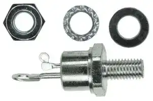
50RIA80
SCR THYRISTOR, 50A, 800V, TO-208AC
⚠️ Reference pricing provided. In case of supply shortages, we will connect you with our trusted procurement partners to ensure your project's continuity.
- Manufacturer: SOLID STATE
- Product type: Thyristors - SCR Modules
- SCR; SCR THYRISTOR, 50A, 800V, TO-208AC; SCR Module Type:Single SCR; Peak Repetitive Off State Voltage:800V; Gate Trigger Current Max:100mA; Average Forward Current:50A; On State RMS C
| Delivery and price | |
|---|---|
| Units per pack | 250 |
| Price | 8.34 € |
| Current stock | 10+ |
| Lead time | 30 days |
Datasheet

S 46BLOOMFIEL FARRAN **D** , STREETNEW JERSEY 07003 www.solidstateinc.com

SSSSSS SSS SS

## SO Amp RMS SCRs

## eS

## Major Ratings and Characteristics

## Description/Features

- PCO... eoT(RMS) Units | —_ generalhis seriespurpose of medium phase power control thyristorsapplications is intendedin converters, for plies and temperature and speed control circuits.

- pe@ Max. Te Pf lighting cirHigh **cu** its,rrent batteryrating. chargers, regulated power suppe r Excellent dynamic characteristics. ©@ 60 Hz B® = dv/dt = 1000V/us option.

- ; a For general purpose applications.

- Pict, @ 60 Hz||0Asco | **S** uperiortandard surgepackage. capabilities. a Metric thread version available.

- 2 a Typesmeeup to 1200VV RRMiv ORM :

## CASE STYLE AND DIMENSIONS

**==> picture [445 x 216] intentionally omitted <==**

**----- Start of picture text -----**<br>
CASE STYLE AND DIMENSIONS pana 228.088) max<br>MAX. 1.83 (0.072)<br>157 (0.062) DIA.<br>re 16.94 (0.667) GA URea DIA.<br>ry DIA. MAX. 1/4-2BUNF-2A<br>\ 4 3.56 (0.140)<br>etA | 754 om | [of 17.35 (0.683)<br>..<br>—_ "JeeAy MAX.30.93 5-087.62  (0 .3-2 00) foey(oie IS| 17.20TLaTS (0.677)<br>14.35 (0.565) 3.58 (0.141) 5,<br>MAX. . 3.33 (0.131) 5 11.4310.80 (0.450)(0.425)<br>} a. — - a7f 1-9055.08 (0.075)(0.200<br>3 i een Se 3.05 (0.120)<br>- MIN. 14.35 (0.565)<br>E: |~~ 30.93MAX (1 . 218) MAK.<br>1/4-28UNF-2A Conforms to JEDEC : TO—208AC (TO-65)<br>All Dimensions in Millimeters and (Inches)<br>**----- End of picture text -----**<br>


50RIA Series

## VOLTAGE RATINGS (Applied gate voltage zero or negative.)

||||||IRM, 'DM — Max.|
|---|---|---|---|---|---|
||v|v<br>RRM,<br>“DRM —|||Peak Reverse and<br>Off-State Current|
||Max.||Repetitive Peak||Vrasm — Max.<br>at Rated VRRM and VoRM|
||||Reverse or||Non-Repetitive Peak<br>Zero Gate Bias Voltage,|
||Off-State Voltage<br>(Vv)<br>@||||Reverse Voltage<br>Gate Open Circuited<br>(Vv)<br>®<br>(mA)|
|Part Number (@)|Ty =||-40°C to 125°C||Ty = 25°C to 125°C<br>Ty = 125°C:|
|SORIAS|||50||100|
|50RIA10|||100||150|
|50RIA20|||200||300|
|5ORIA40|||400||500|
|50RIA60|||600||700|
|50RIA80|||800||900|
|50R1A100|||1000||1100|
|50R1A120|||1200||1300|
|ELECTRICAL SPECIFICATIONS||||||
|Ys<br>onions<br>CS<br>ON-STATE||||||
|It(av)<br>Max.average on-state current|||| so ||aA ||Tc=94°Cmax.,180° sinusoidal conduction.|
|Itsm<br>Max. peak one cycle, non-<br>repetitive surge current|||1200<br>1255<br>| 1430 |<br>1490|A|50 Hz half cycle sine wave<br>Followingany rated load condition,<br>or 6ms rectangular pulse<br>and with ratedVaR applied<br>60 Hz halfcycle sinewave<br>following surge.<br>or 5 ms rectangular pulse<br>SCR turned fully on.<br>50 Hzhalfcyclesinewave ~—Foljowing any ratedloadcondition,<br>or6ms rectangular pulse<br>and withVaro following<br>60 Hz half cycle sinewave<br>-<br>or 5ms rectangular pulse<br>surge<br>0.|
|124<br>Max. 124 capability,for<br>fusing|||7200<br>| 6560 ||A2s|t=10ms<br>RatedVarryapplied followingsurge,<br>t=8.3ms<br>initial Ty= 125°C,|
|12¢<br>Max. |“t capability, for<br>individual device fusing|||10180<br>9300|2<br>A‘s|t= 10ms<br>a<br>°<br>t=8.3ms<br>Varm following surge = 0, initial Ty = 125°C.|
|\2Vt<br>Max. 124/ t capability, <br>individual device fusing|for<br> @||101,800|2<br>AtvVs|_<br>.<br>eas<br>t=0.1 to 10ms,Vang following surge = 0, initial Ty = 125°C.|
|Vt<br>Max,peakon-statevoltage|||| 16 ||Vv|Ty=25°C, IT(AV) =50A (157Apeak)|
|Vy<br>Max. holding current|||||Ty = 25°C, anode supply = 22V, initial I7 = 2.0A.|
|I<br>Max. latchingcurrent|||| 400 ||ma ||Anodesupply=6V,resistive load|
|BLOCKING||||||
|dv/dt<br>Min. critical rate-of-rise <br>off-state voltage|of||200<br>t<br>.<br>500|Vius|Ty= 125°C. Exponential<br>to 100% ratedVoRm<br>Zero gate bias voltage,<br>Ty = 125°C. Exponential<br>gateopen circuited.<br>to67%ratedVornyy|


‘O) For yoltage pulses with t, <5ms. ‘) Units may be: brqken over non-repetitively in the off-state direction without damage, if di/dt does not exceed 20 A/ys. @® 2+ fortimet, = 12Vt « Vy

® For M6 threads add ““M” to code, e.g., SOR!|AGOM.

t Available with dv/dt = 1000V/us, (Ty = 125°C, exponential to 67% VpRM). Add S90 to part number, e.g. SORIAGOS90.

5ORIA Series

## ELECTRICAL SPECIFICATIONS (Continued)

|a|a|||||
|---|---|---|---|---|---|
||SWITCHING|||||
|ty|Typical delay time||||Tc 25°C, Vpm = rated Vorm. !tm = 10A de resistive circuit,|
|||||us|Gate pulse: 10V, 152 source, to = 20 us.|
|di/dt|Max. non-repetitive rate of<br>rise of turned-on current<br>Varm=_50 to 600V<br>= 700 to 1200V|200||Alus|Te = 125°C, Vom = ratedVor, !tm = 2 x rated di/dt,<br>Gate pulse: 20V, 159, t, = 6 us, t, = 0.1 wsmax.<br>PerJEDEC standard RS-397, 5.2.7.6.|
|tg|Typical turn-off time||||To= 125°C, lt = S0A, di/dt = -10 A/us, Vp during turn-off|
|||110||Us|interval = 50V min., reapplied dv/dt = 20 V/us linear to rated|
||||||VormM:- Gate bias: OV, 1002.|
||TRIGGERING|||||
|lom|Max. peak positive gate<br>current|2.5||A||
|+VGm|Max. peak positive gate<br>voltage|20||V||
|-VGm|Max. peak negative gate<br>voltage|||V||
|IGT|Max. required DC gate<br>current to trigger|| 100|||mA|Ty = _40°C<br>Max. required gate trigger current is<br>Ty =25°C<br>the lowest valuewhich will trigger<br>all units with +6V anode-to-cathode.|
|VoT|Max. required DC gate<br>voltage to trigger|||Vv|Ty = —40°C<br>Max. required gate trigger voltage is<br>3<br>the lowest value which will trigger<br>Ty = 25°C<br>all units with +6V anode-to-cathode.|
|VED|Max. DCgate voltage<br>not to trigger||||Ty = 125°C<br>Max. gate current or voltage not to<br>trigger is the maximum value which|
|I6p|Max.DCgatecurrent<br>not to trigger|||mA|Ty = 125°C,<br>vill not triggerany “nitwith rated<br>Vorm = fated voltage<br>DRM anode-to-cathode.|
|THERMAL-MECHANICAL SPECIFICATIONS||||||
|Ty|Operating junction<br>temperature range|~40 to 125||oO<br>Cc||
|R<br>thJC|Max. internal thermal||||:|
|Pthes|ine resistance,case to|0.25||deg.C/W|Mounting surface smooth, flat and greased.|
|T|Mounting torque|||||
||Min.<br>Max.|2.8 (25)<br>3.4 (30)||Nem<br>.<br>(Ibf-in)|.<br>Non-lubricated threads|
||Case Style|TO-208AC||||
|||(TO-65)||||


5ORIA Series

**==> picture [506 x 601] intentionally omitted <==**

**----- Start of picture text -----**<br>
a, 140-LITTTTTT itt tt ttt 5. 0tt |<br>g eee raees: Yt tt<br>= PSSST SS ee<br>2 a | NSSSEEREDCOEEP Tg, CC USSS88 588i LO<br>Pee POA ST Pe TT 3 itt tt IN Ses A ia Ban<br>ee eeee ae eeee<br>eee Sisrenee!<br>So2 LerTT TT TT snesTt  Mi g MbcesPPP ee gesCenereavisee<br>22.HBSCET TT NANT TT ANT TTT Sopes [ittiiPrueft tii tT porePp<br>2 CE T PTUNNYTaREA TTTt a2 LiteeTt TTT.eeconouctiowreriooiefT<br>pL 0 LL10 TE20 TET30 ATT40 Teovoucrigwanctel{50 60 70 80 [|90 | J100 ott 0 10 tt20 tdi30 40 ti50 ti60 tii70 80 90 7100<br>AVERAGE ON-STATE CURRENT OVER FULL CYCLE (AMPERES) AVERAGE ON-STATE CURRENT OVER FULL CYCLE (AMPERES)<br>Fig. 1 — On-State Current Vs. Case Temperature Fig. 2 — On-State Current Vs. Case Temperature<br>(Sinusoidal Current Waveform, 50 to 400 Hz) (Rectangular Current Waveform, 50 to 400 Hz)<br>a=<br>a<br>5 CONTROLLED RECTIFIERj pT7T TT AT YA 3 5 Ty= 125°C Nigh @muaiiit<br>= 10 TURNED FULLY ON HAA| AY > CONTROLLED RECTIFIER TURNED FULLY ON HO<br>2 XK \4 4 i i tii A<br>s ofttLE} aes an y aro aan cry eZ<br>& fT fuez Ao Le ae a OZ r208 TH<br>gag3 sop ttfLoi |] 0NNf [NIZA] A Aereeee| et BSB02  NYE eee TT<br>2BCP oteCh a aw,ee —ae ama tt S2 FSSREPeerEe<br>5  pt SA ee£0. Z , Ree uth<br>SOCOLLONE eee Ope NH cH<br>ar Aer eeeCARE 2 PEEP Violi Vir ALT<br>= Ze 6 LLL WTpe<br>28 20 Sep”LOL;Weaaneeeeeennam | ,> a= ee 2 annll)/Y ¢  MOC<br>s 10 [i;] ep Jeuenneneae10 15-20 5 30 35 oc40. ANGLE45  =50 Zz wE LTAVERAGETUT ON-STATE MA CURRENT OVER| AMATI FULL CYCLE|  (AMPERES); LLU<br>AVERAGE ON-STATE CURRENT OVER FULL CYCLE (AMPERES)<br>Fig. 3 — Maximum Low-Level On-State Power Loss Fig. 4 — Maximum High-Level On-State Power Loss<br>Vs. Current (Sinusoidal Current Waveform) Vs. Current (Sinusoidal Current Waveform)<br>2 90 =<br>== aot Ty= 125% [eyTTT iA TA $ FEA acted eZee<br>3 70 CONTTU R OLLEDNED FULLY ON RECTIFIER yiamttaware.Yi yin ranS CONTROLLED RECTIFIERTy 125°C TURNED FULLY ON [||c/s7A7A ZT TTTeee<br>fore eer Ny<br>S IWS IAAAATT  g weTN<br>6= it 120°] WhWW YEELo 4 wa 3~ FfaS— 800DOSSSa SS SS OS 7, eS |<br>a3 40 :LnSeeSONIA rt eeES SEERNISS<br>28 RAT NV Za A :Ss COC SY tetzl<br>=z Pit oYAgeeae tt < yeY CONDUCTION PERIODall| |<br>2,2 I iaa E+ Jt | a eZ<br>a 10 * yA tt CONDUCTION PERIOD eye102 5WW |2 i5?| 2| LLU5108<br>z 0 5 10 15 20 25 30 35 40 45 50 < AVERAGE ON-STATE CURRENT OVER FULL CYCLE (AMPERES)<br>AVERAGE ON-STATE CURRENT OVER FULL CYCLE (AMPERES)<br>**----- End of picture text -----**<br>


Fig. 5 — Maximum Low-Level On-State Power Loss Vs. Current (Rectangular Current Waveform)

Fig. 6 — Maximum High-Level On-State Power Loss Vs. Current (Rectangular Current Waveform)

5ORIA Series

**==> picture [471 x 594] intentionally omitted <==**

**----- Start of picture text -----**<br>
ws = 1400<br>SSSSS aaa SS 2 [LT TTT Tt [TTT]<br>6 §—— >} +} +} = ooh + | | PTT TT TTT<br>Seer z NEL |<br>z=, | [TA fT fT ft ft 5 AT ANY RATED LOAD CONDITION<br>a A A = oon | SY TTT CO OWING SURE RRM APPLIEO i<br>opi]7| ff ft | {| | {| - {| [SALUT] i<br>7w =SS ee ee | ft |TTT<br>7 Tf < ff dT EC a rf | TT Til<br>aaoo!Fry = vase fAff FpaSgA B5 oot ___| | [I —PHar<br>Ss<br>5 tt controuen necririen 2 o-—__| | TTT TT tT Titty<br>a a tt og<br>2.6 0[Tt05 10 TT15 TT]20 25 30 7 35 40 45 50 ey | 2PT TTT4 6 8 10 tT 20ET 40ETT60100<br>INSTANTANEOUS ON-STATE VOLTAGE (VOLTS) NUMBER OF EQUAL AMPLITUDE HALF CYCLE CURRENT PULSES (N)<br>Fig. 7 — Maximum On-State Voltage Vs. Current Fig. 8 — Maximum Non-Repetitive Surge Current<br>Vs. Number of Current Pulses<br>'0"2 ee<br>Esunction - 0350 CONVERTER GS<br>3 SPRECTANGULAR GaTE PULSE || FFE eed<br>5 (A) RECOMMENDED LOAD LINE TT err<br>8 FOR RATED di/dt= 20V, TE LT IN Ie<br>oO= 10 FOR <30% RATED di/dt = 20V 4a,oi 4d NNO\! NYS< ‘SoS (6{ SESS<br>rf3> 5 650, rityty = 1 Us, ty. 6 ps ETONPoTaN RSERHEN. OnFN 6 FANSNO6. SN INOONOSEeTDea<br>&eo poi eeSTATS, “Ss %, NT TT<br>2 sti ih bs NO NAR SR SEHil<br>2 Pan ee ale tic eM | tt<br>Pas=Z 105 ee peeaosee occfortsnl iPpta SHSae es {FREQUENCYBY PG(AV)  LIMITED EH{H<br>2 10s ye an<br>= piVenPittLie| e t aanPe rm TET PT<br>260 TT TT<br>wr LLL tee PT TE<br>10-32 5 19-2 2 5 19-1 2 5 10 2 5 10 2 5 192<br>INSTANTANEOUS GATE CURRENT (AMPERES)<br>Fig. 9 — Gate Characteristics<br>0swe2 se2 5 ws2 5 we2 5 2 65 103<br>= Sr eee0<br>sett bettine ouaariaa<br>bes |_| PoeTer es<br>w= aH TE tT actiqatin,<br>2<aCrpTTon etPeritLUTra008TT ETE eeeae TT ETT 5<br>2 2D aT ETT,<br>=Sy ceeSPAT TT one rimeetourations+-et ETee FETTT<br>=SCHMITTZ eer0aa S ALL TeMLL TH CONTROLLEDcomraouteo RECTIFIERnecriries ane)an1<br>= w2LTL Tn TT Tn TTTTT) 10<br>w22 5 wt2 5 yo 2 5 w 2 5 422 5 493<br>SQUARE WAVE PULSE DURATION (SECONDS)<br>**----- End of picture text -----**<br>


Fig. 10 — Maximum Transient Thermal !mpedance, Junction-To-Case Vs. Square Wave Pulse Duration

50RIA Series

**==> picture [431 x 595] intentionally omitted <==**

**----- Start of picture text -----**<br>
“CTT TT TTT TTT TIN TAT TET<br>wt ttt ttt ty TANT IN VAL<br>_ FEERRRECECTAZOZOCENAE Ce NESOT [eee<br>[Pet]<br>CCOERCOPALAT [ALE]] a |<br>LER SLCC NT Fe<br>: NA Ee KE || ee ae<br>: o | Oa A BSS ON AU YET) [eee<br>g OY AA eS NENN<br>Espases YA Abobo ING N A Ree<br>eVPLfeetTBATVe)TTeaettTTtT PSereANNANPEINN ANATANTAN TETTTT<br>7/2 Hee S RNNe<br>COC)<br>AVERAGE ON-STATE CURRENT OVER FULL CYCLE (AMPERES) MAXIMUM ALLOWABLE AMBIENT TEMPERATURE (°C)<br>Fig. 11 — Thermal Nomogram (Sinusoidal Current<br>Waveform, 40 to 400 Hz)<br>80 PTT TTT TT yt ya IN TN ET<br>ott ttt tt tar tA AT IN | LT<br>e COCOAPTT tT TT TTY YN MEY)<br>= L_cpermtoustosinndTAY TAT ATNATAT Net tp [tt]<br>CORT ISCNE NS<br>SL] fe AIZA VT TL TIN TE Re LAS | eae<br>BP OOCROCEEELE RD Me] Le Peo<br>g PS YA A NIN<br>E aioel ttt 8g S KAAE<br>2 EE aan =s=t INKANTTL<br>nwPT 224 P| te) T [INNA] ANAL ET Te<br>AYE tT tt tT Pet PN AANAR TE TEE<br>(om eee SaNNEEee<br>AA| gel TT TE TT TT PettPAIN<br>Mittin tet TT<br>0 10 20 30 40 tt50 60.30tt40 tint60 80tt 100PS120 Xy ty140 160<br>AVERAGE ON-STATE CURRENT OVER FULL CYCLE (AMPERES) MAXIMUM ALLOWABLE AMBIENT TEMPERATURE (°C)<br>**----- End of picture text -----**<br>


Fig. 12 — Thermal Nomogram (Rectangular Current Waveform, 40 to 400 Hz)

Notes: A. Maximum allowable heatsink thermal resistance, Ripga, equals the graph value minus the ARyp factor which allows for instantaneous Ty excursion. B. Caution. Data assumes that the controlled rectifier is mounted with thermally conductive grease to achieve Ryncg = 0.25 deg.C/W.
Updated at June 7, 2026
About Novapart
Novapart is a B2B electronic component broker specialising in stock shortages and cost reduction. We source hard-to-find parts and identify compliant alternatives across a catalogue of 410,000+ components from 500+ manufacturers.
Learn more →Stock Shortage Specialist
When a component is unavailable, discontinued or has an unacceptable lead time, we tap into our network of vetted European and Asian distributors to source what you need — without compromising on quality or traceability.
Request a quote →Compliant Alternatives
We identify pin-to-pin, electrically equivalent substitutes that meet the same certifications (RoHS, AEC-Q100, REACH) as your original specification — validated against datasheets, not just part numbers. Often at a lower cost.
BOM Analysis service →