
Image not available
Illustrative purposes only

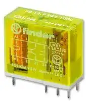
50.12.9.005.1000
Safety Relay, 5 VDC, DPDT, 50 Series, Through Hole, 8 A, Solder
⚠️ Reference pricing provided. In case of supply shortages, we will connect you with our trusted procurement partners to ensure your project's continuity.
- Manufacturer: FINDER
- Product type: Safety Relays
- Coil Voltage:5VDC; Contact Configuration:DPDT; Product Range:50.12 Series; Relay Mounting:Through Hole; Contact Current:8A; Relay Terminals:Solder; Contact Voltage AC Nom:250V; Contact Vo
- SVHC: No SVHC (04-Feb-2026)
- IP Rating: -
- Coil Voltage: 5VDC
- Product Range: 50 Series
- Relay Mounting: Through Hole
- Contact Current: 8A
- Relay Terminals: Solder
- Contact Material: Silver Nickel
- Contact Configuration: DPDT
- Contact Voltage AC Nom: 250V
- Contact Voltage DC Nom: -
| Delivery and price | |
|---|---|
| Units per pack | 50 |
| Price | 9.98 € |
| Current stock | 500+ |
| Lead time | 30 days |
Datasheet

**50 SERIES**

**C**

**PCB Relay with forcibly guided contacts according to EN 50205 type B**

**==> picture [171 x 7] intentionally omitted <==**

**----- Start of picture text -----**<br>
50.12…1000 50.12…5000<br>**----- End of picture text -----**<br>


## **2 CO contacts***

- High physical separation between adjacent contacts

- Cadmium Free contact materials

- 8 mm, 6 kV (1.2/50 µs) isolation, coil-contacts

- Flux proof: RT II

- For medium duty switching, • For safety applications suggested for DC loads • Gold plate contacts for low Gold plate contacts for low

   - Gold plate contacts for low Gold plate contacts for low level switching capability

- 2 Pole 8 A

- 5 mm pinning

      - 5 mm pinning

   - PCB mounting • PCB mounting

- According to E N 50205 only 1 NO and 1 NC (11-14 and 21-22 or 11-12 and 21-24) shall be used as forcibly guided contacts.

_For UL ratings see:_

_“General technical information” page_ V

||_For UL ratingsor UL ratings UL ratingsratings see::_<br>_“General technical information” pageGeneral technical information” page_|_For UL ratingsor UL ratings UL ratingsratings see::_<br>_“General technical information” pageGeneral technical information” page_|||
|---|---|---|---|---|
||_“General technical information” pageGeneral technical information” page” pagepage_V<br>**Contact specification**<br>Contact configuration||Copper side view<br>2 CO (DPDT)|Copper side view<br>2 CO (DPDT)|
||Rated current/Maximumpeak current<br>A||8/15|8/15|
||Rated voltage/<br>Maximum switchingvoltage|V AC|250/400|250/400|
||Rated load AC1|VA|2000|2000|
||Rated load AC15 (230 V AC)|VA|500|500|
||Singlephase motor rating(230 V AC)<br>kW||0.37|0.37|
||BreakingcapacityDC1: 30/110/220 V<br>A||8/0.65/0.2|8/0.65/0.2|
||Minimum switchingload|mW (V/mA)|500 (10/10)|50 (5/5)|
||Standard contact material<br>**Coil specification**<br>Nominal voltage (UN)|V AC (50/60 Hz)|AgNi<br>—|AgNi + Au<br>—|
|||V DC|5 - 6 - 12 - 24 - 48 - 60 - 110 - 125|5 - 6 - 12 - 24 - 48 - 60 - 110 - 125|
||Ratedpower AC/DC|VA (50 Hz)/W|—/0.7|—/0.7|
||Operating range|AC (50 Hz)|—|—|
|||DC|(0.75…1.2)UN|(0.75…1.2)UN|
||Holdingvoltage|AC/DC|—/0.4 UN|—/0.4 UN|
||Must drop-out voltage<br>**Technical data**|AC/DC|—/0.1 UN|—/0.1 UN|
||Mechanical life AC/DC|cycles|—/10 · 106|—/10 · 106|
||Electrical life at rated load AC1|cycles|100 · 103|100 · 103|
||Operate/release time|ms|10/4|10/4|
||Insulation between coil||||
|I-2016, www.findernet.com|and contacts(1.2/50µs)<br>Dielectric strength<br>between open contacts<br>Ambient temperature range<br>Environmentalprotection<br>**Approvals**(according to type)|kV<br>V AC<br>°C|6(8 mm)<br>1500<br>–40…+70<br>RT II<br>Hl & ®|6(8 mm)<br>1500<br>–40…+70<br>RT II<br> A Wis|


**1**

**50 SERIES**

**B**

## **Ordering information**

Example:  50 series forcibly guided contacts, 2 CO (DPDT) 8 A contacts, 24 V DC coil.

**A**

## **5 0 . 1 2 . 9 . 0 2 4 . 5**

**C D**

## **0 0 0**

**C**

## **Series**

**Type**

1 =  PCB - 5 mm pinning

## **No. of poles**

## **A: Contact material**

1 =  Standard AgNi

5 =  AgNi + Au

**B: Contact circuit**

0 =  CO (DPDT)

## **D: Special versions**

0 =  Flux proof (RT II)

**C: Options**

0 =  None

2 =  2 pole 8 A

## **Coil version**

9 =  DC

**Coil voltage**

See coil specifications

**Selecting features and options: only combinations in the same row are possible.** Preferred selections for best availability are shown in **bold.**

|**Type**|**Coil version**|**A**|**B**|**C**|**D**|
|---|---|---|---|---|---|
|50.12|DC|**1**- 5|**0**|**0**|**0**|


## **Technical data**

## **Insulation according to EN 61810-1**

|Nominal voltage of supplysystem<br>V AC|Nominal voltage of supplysystem<br>V AC|230/400|230/400|
|---|---|---|---|
|Rated insulation voltage<br>V AC||250|400|
|Pollution degree||3|2|
|**Insulation between coil and contact set**||||
|Type of insulation||Reinforced (8 mm)||
|Overvoltage category||III||
|Rated impulse voltage<br>kV (1.2/50µs)||6||
|Dielectric strength<br>V AC||4000||
|**Insulation between adjacent contacts**||||
|Type of insulation||Basic||
|Overvoltage category||III||
|Rated impulse voltage<br>kV (1.2/50µs)||4||
|Dielectric strength<br>V AC||3000||
|**Insulation between open contacts**||||
|Type of disconnection||Micro-disconnection||
|Dielectric strength<br>V AC/kV (1.2/50 µs)||1500/2.5||
|**Conducted disturbance immunity**||||
|Burst (5…50)ns, 5 kHz, on A1 - A2||EN 61000-4-4|level 4 (4 kV)|
|Surge (1.2/50 µs) on A1 - A2 (differential mode)||EN 61000-4-5|level 3 (2 kV)|
|**Other data**||||
|Bounce time: NO/NC<br>ms||2/10||
|Vibration resistance (10…200)Hz: NO/NC<br>g||20/6||
|Shock resistance NO/NC|g|20/5||
|Power lost to the environment|without contact current<br>W|0.7||
||with rated current<br>W|1.2||
|Recommended distance between relays mounted on PCB<br>mm||≥ 5||


**2**

**50 SERIES**

**C**

## **Contact specification**

**F 50 - Electrical life (AC) v contact current**

**==> picture [214 x 109] intentionally omitted <==**

**----- Start of picture text -----**<br>
Resistive load - cosφ = 1<br>Inductive load - cosφ = 0.4<br>Cycles<br>**----- End of picture text -----**<br>


## **H 50 - Maximum DC1 breaking capacity**

**==> picture [214 x 127] intentionally omitted <==**

**----- Start of picture text -----**<br>
DC voltage (V)<br>DC breaking current (A)<br>**----- End of picture text -----**<br>


- When switching a resistive load (DC1) having voltage and current values under the curve, an electrical life of ≥ 100 · 10[3] can be expected.

- In the case of DC13 loads, the connection of a diode in parallel with the load will permit a similar electrical life as for a DC1 load. Note: the release time for the load will be increased.

**==> picture [123 x 76] intentionally omitted <==**

**==> picture [120 x 41] intentionally omitted <==**

**----- Start of picture text -----**<br>
Alternative selection of NO and NC<br>contacts to provide Forcibly guided<br>(mechanically linked) contacts, in<br>accordance with EN 50205 (type B).<br>**----- End of picture text -----**<br>


## **Coil specifications**

**R 50 -  DC coil operating range v ambient temperature**

## **DC coil data**

|Nominal<br>voltage<br>UN|Coil<br>code|Operating range<br>Umin<br>Umax|Operating range<br>Umin<br>Umax|Resistance<br>R|Rated coil<br>consumption<br>Iat UN|
|---|---|---|---|---|---|
|V||V|V|Ω|mA|
|5|**9**.005|3.8|6|35|143|
|6|**9**.006|4.5|7.2|50|120|
|12|**9**.012|9|14.4|205|58.5|
|24|**9**.024|18|28.8|820|29.3|
|48|**9**.048|36|57.6|3280|14.4|
|60|**9**.060|45|72|5140|11.7|
|110|**9**.110|82.5|131|17250|6.4|
|125|**9**.125|93.7|150|22300|5.6|


## Standard coil

**==> picture [216 x 128] intentionally omitted <==**

**==> picture [106 x 8] intentionally omitted <==**

**----- Start of picture text -----**<br>
1 -   Max. permitted coil voltage.<br>**----- End of picture text -----**<br>


**2 -** Min. pick-up voltage with coil at ambient temperature.

**3**
Updated at June 5, 2026
About Novapart
Novapart is a B2B electronic component broker specialising in stock shortages and cost reduction. We source hard-to-find parts and identify compliant alternatives across a catalogue of 410,000+ components from 500+ manufacturers.
Learn more →Stock Shortage Specialist
When a component is unavailable, discontinued or has an unacceptable lead time, we tap into our network of vetted European and Asian distributors to source what you need — without compromising on quality or traceability.
Request a quote →Compliant Alternatives
We identify pin-to-pin, electrically equivalent substitutes that meet the same certifications (RoHS, AEC-Q100, REACH) as your original specification — validated against datasheets, not just part numbers. Often at a lower cost.
BOM Analysis service →