
Image not available
Illustrative purposes only

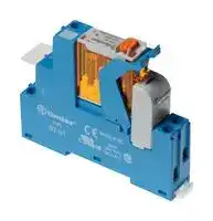
4C0180240060SPA
Power Relay, SPDT, 24 VAC, 16 A, 4C Series, DIN Rail
⚠️ Reference pricing provided. In case of supply shortages, we will connect you with our trusted procurement partners to ensure your project's continuity.
- Manufacturer: FINDER
- Product type: Power Relays
- Contact Configuration:SPDT; Coil Voltage:24VAC; Contact Current:16A; Product Range:4C Series; Relay Mounting:DIN Rail; Coil Type:-; Contact Voltage VAC:250V; Relay Terminals:Screw
- SVHC: No SVHC (04-Feb-2026)
- Coil Type: -
- Coil Voltage: 24VAC
- Product Range: 4C Series
- Relay Mounting: DIN Rail
- Coil Resistance: 320ohm
- Contact Current: 16A
- Relay Terminals: Screw
- Contact Material: Silver Nickel
- Contact Voltage VAC: 250V
- Contact Voltage VDC: -
- Contact Configuration: SPDT
| Delivery and price | |
|---|---|
| Units per pack | 50 |
| Price | 15.57 € |
| Current stock | 10+ |
| Lead time | 30 days |
Datasheet

~~fi~~ nder SWITCH TO THE FUTURE Relay interface y modules 8 - 10 - 16 A ® c Escalators = : | * Road / tunnel lighting Hoists and cranes Ba wa _—~‘ @& # Sy _ Nine, Se. ‘ Carousel warehouses Control panels ~~SH~~ 4 Panels for electrical distribution

**4C SЕRIES**

FINDER reserves the right to alter characteristics at any time without notice. FINDER assumes no liability for damage to persons or property, caused as a result of the incorrect use or application of its products.

**4C SERIES**

**B**

**1 & 2 CO relay interface modules, 15.8 mm wide with Push-in terminal Ideal interface for PLC and electronic systems Type 4C.P1**

**==> picture [140 x 8] intentionally omitted <==**

**----- Start of picture text -----**<br>
4C.P1 4C.P2<br>**----- End of picture text -----**<br>


- 1 CO 10 A **Type 4C.P2**

- 2 CO 8 A

- AC coils or DC coils

- Supply status indication and coil suppression module as standard

- Identification label

- UL Listing (certain relay/socket combinations) • 35 mm rail (EN 60715) mounting

- 1 CO 10 A • 2 CO 8 A • Push-in terminals • Push-in terminals

4C.P1 / 4C.P2

Push-in terminals

For outline drawing see page 7

|For outline drawing see page 7|||||
|---|---|---|---|---|
|**Contact specification**<br>Contact configuration||1 CO (SPDT)||2 CO (DPDT)|
|Rated current/Maximum peak current<br>A||10/25||8/15|
|Rated voltage/<br>Maximum switchingvoltage|V AC|250/440||250/440|
|Rated load AC1|VA|2500||2000|
|Rated load AC15 (230 V AC)|VA|750||350|
|Single phase motor rating (230 V AC)<br>kW||0.55||0.37|
|Breaking capacity DC1: 30/110/220 V<br>A||10/0.5/0.15||6/0.5/0.15|
|Minimum switching load|mW (V/mA)|300 (5/5)||300 (5/5)|
|Standard contact material<br>**Coil specification**<br>Nominal voltage (UN)|V AC (50/60 Hz)|AgNi<br>12 - 24 - 110 - 120 - 230|AgNi<br>12 - 24 - 110 - 120 - 230||
||V DC|12 - 24 - 125||12 - 24 - 125|
|Rated power AC/DC|VA (50 Hz)/W|1.2/0.5||1.2/0.5|
|Operating range|AC|(0.8…1.1)UN||(0.8…1.1)UN|
||DC|(0.73…1.1)UN|(0.73…1.1)UN||
|Holding voltage|AC/DC|0.8 UN/ 0.4 UN|0.8 UN/ 0.4 UN||
|Must drop-out voltage<br>**Technical data**|AC/DC|0.2 UN/ 0.1 UN|0.2 UN/ 0.1 UN||
|Mechanical life AC/DC|cycles|10 · 106||10 · 106|
|Electrical life at rated load AC1|cycles|100 · 103||100 · 103|
|Operate/release time|ms|15/5 (AC) - 15/12 (DC)|10/3 (AC) - 10/10 (DC)|10/3 (AC) - 10/10 (DC)|
|Insulation between coil|||||
|and contacts(1.2/50μs)<br>kV<br>Dielectric strength<br>between open contacts<br>V AC<br>Ambient temperature range<br>°C<br>Protection category<br>**Approvals relay**(according to type)||6(8 mm)<br>1000<br>–40…+70<br>IP 20<br>C€@FAL@|®<br>@Adis|6(8 mm)<br>1000<br>–40…+70<br>IP 20<br>Adis|


**3**

**4C SERIES**

## **1 & 2 CO relay interface modules,**

**==> picture [139 x 8] intentionally omitted <==**

**----- Start of picture text -----**<br>
4C.01 4C.02<br>**----- End of picture text -----**<br>


## **15.8 mm wide with screw terminal**

## **Ideal interface for PLC and electronic systems**

## **Type 4C.01**

- 1 CO 16 A

## **Type 4C.02**

   - 2 CO 8 A

   - AC coils or DC coils

- **B** • Supply status indication and coil suppression module as standard

   - Identification label

   - UL Listing (certain relay/socket combinations)

   - 35 mm rail (EN 60715) mounting

- 1 CO 16 A

   - 2 CO 8 A

- Screw terminals • Screw terminals

4C.01 / 4C.02

Screw terminals

|For outline drawing see page 7|||||||
|---|---|---|---|---|---|---|
|**Contact specification**<br>Contact configuration||1 CO (SPDT)|||2 CO (DPDT)|2 CO (DPDT)|
|Rated current/Maximum peak current<br>A||16/25||||8/15|
|Rated voltage/<br>Maximum switchingvoltage|V AC|250/440||||250/440|
|Rated load AC1|VA|4000||||2000|
|Rated load AC15 (230 V AC)|VA|750||||350|
|Single phase motor rating (230 V AC)<br>kW||0.55||||0.37|
|Breaking capacity DC1: 30/110/220 V<br>A||16/0.5/0.15|||6/0.5/0.15||
|Minimum switching load|mW (V/mA)|300 (5/5)||||300 (5/5)|
|Standard contact material<br>**Coil specification**<br>Nominal voltage (UN)|V AC (50/60 Hz)|AgNi<br>12 - 24 - 110 - 120 - 230||12 - 24 - 110 - 120 - 230||AgNi<br>12 - 24 - 110 - 120 - 230|
||V DC|12 - 24 - 125|||12 - 24 - 125||
|Rated power AC/DC|VA (50 Hz)/W|1.2/0.5||||1.2/0.5|
|Operating range|AC|(0.8…1.1)UN|||(0.8…1.1)UN||
||DC|(0.73…1.1)UN||(0.73…1.1)UN|||
|Holding voltage|AC/DC|0.8 UN/ 0.4 UN||0.8 UN/ 0.4 UN|||
|Must drop-out voltage<br>**Technical data**|AC/DC|0.2 UN/ 0.1 UN||0.2 UN/ 0.1 UN|||
|Mechanical life AC/DC|cycles|10 · 106||||10 · 106|
|Electrical life at rated load AC1|cycles|100 · 103||||100 · 103|
|Operate/release time|ms|15/5 (AC) - 15/12 (DC)||10/3 (AC) - 10/10 (DC)|10/3 (AC) - 10/10 (DC)||
|Insulation between coil|||||||
|and contacts(1.2/50μs)|kV|6(8 mm)||||6(8 mm)|
|Dielectric strength|||||||
|between open contacts|V AC|1000||||1000|
|Ambient temperature range|°C|≤ 12 A: –40…+70/>12 A: –40…+50|||–40…+70||
|Protection category||IP 20||||IP 20|
|**Approvals relay**(according to type)||CE@FAL©|©|®<br>Adis|Adis||


**4**

**4C SERIES**

**B**

## **Ordering information**

Example:  4C series, 35 mm rail (EN 60715) mount, Push-in terminal relay interface module, 1 CO 10 A contacts, 24 V DC coil, green LED + diode.

**A B C D**

**4 C . P 1 . 9 . 0 2 4 . 0 0 5 0 A: Contact material D: Special versions** 0 =  AgNi

## **D: Special versions**

## **Series**

0 =  Standard

- 4 =  AgSnO2

**Type**

- 0 =  35 mm rail (EN 60715) mount screw terminal socket

## **C: Options**

- 5 =  AgNi + Au

   - 5 =  Standard for DC: green LED + diode (polarity +A1)

   - 6 =  Standard for AC: green LED + Varistor

- P =  35 mm rail (EN 60715) mount Push-in terminal socket

## **B: Contact circuit**

- 0 =  CO (nPDT)

## **No. of poles**

1 =  1 pole, 10/16 A 2 =  2 pole, 8 A

## **Coil version**

- 8 =  AC (50/60 Hz)

9 =  DC

## **Coil voltage**

See coil specifications

**Selecting features and options: only combinations in the same row are possible.** Preferred selections for best availability are shown in **bold.**

|**Type**|**Coil version**|**A**|||||**B**|**C**|**D**|
|---|---|---|---|---|---|---|---|---|---|
|4C.02|AC|**0**|-|5|||**0**|**6**|**0**|
|4C.P2|DC|**0**|-|5|||**0**|**5**|**0**|
|4C.01|AC|**0**|-|4|-|5|**0**|**6**|**0**|
|4C.P1|DC|**0**|-|4|-|5|**0**|**5**|**0**|


## **Technical data**

## **Insulation**

|Insulation according to EN 61810-1|insulation rated voltage<br>V|insulation rated voltage<br>V|250|250|440|440|
|---|---|---|---|---|---|---|
||rated impulse withstand voltage  kV||4||4||
||pollution degree||3||2||
||overvoltage category||III||III||
|Insulation between coil and contacts (1.2/50 μs)<br>kV|||6 (8 mm)||||
|Dielectric strength between open contacts<br>V AC|||1000||||
|Dielectric strength between adjacent contacts<br>V AC|||2000||||
|**Insulation between coil terminals**|||||||
|Rated impulse voltage (surge) differential mode<br>(according to EN 61000-4-5)<br>kV(1.2/50 µs)|||2||||
|**Other data**|||||||
|Bounce time: NO/NC||ms|2/6 (4C.01/P1)||1/4 (4C.02/P2)||
|Vibration resistance (10…150)Hz: NO/NC||g|20/12||||
|Power lost to the environment|without contact current|W|0.6||||
||with rated current|W|1.6 (4C.01/P1)||2 (4C.02/P2)||
|**Terminals**|||**4C.01/4C.02**||**4C.P1/4C.P2**||
|Wire strip length||mm|8||8||
|Screw torque||Nm|0.8||—||
|Min. wire size||mm2|solid cable|stranded cable|solid cable|stranded cable|
||||0.5|0.5|0.5|0.5|
|||AWG|21|21|21|21|
|Max. wire size||mm2|solid cable|stranded cable|solid cable|stranded cable|
||||1 x 6 / 2 x 2.5|1 x 4 / 2 x 2.5|2 x 1.5 / 1 x 2.5|2 x 1.5 / 1 x 2.5|
|||AWG|1 x 10 / 2 x 14|1 x 12 / 2 x 14|2 x 16 / 1 x 14|2 x 16 / 1 x 14|


**5**

**4C SERIES**

## **Contact specification**

**B**

## **F 4C - Electrical life (AC) v contact current**

**==> picture [253 x 459] intentionally omitted <==**

**----- Start of picture text -----**<br>
Types 4C.02/P2<br>Resistive load - cosφ = 1<br>Inductive load - cosφ = 0.4<br>H 4C - Maximum DC1 breaking capacity<br>Current limit 1 CO (SPDT) (*)<br>Current limit 2 CO (DPDT)<br>DC voltage (V)<br>Coil specifications<br>DC coil data<br>Nominal  Coil code Operating range Resistance Rated coil<br>voltage consumption<br>UN Umin Umax R I at UN<br>V V V Ω mA<br>12 9 .012 8.8 13.2 300 40<br>24 9 .024 17.5 26.4 1200 20<br>125 9 .125 91.2 138 32000 3.9<br>Cycles<br>DC breaking current (A)<br>**----- End of picture text -----**<br>


## **F 4C - Electrical life (AC) v contact current**

**==> picture [253 x 149] intentionally omitted <==**

**----- Start of picture text -----**<br>
Types 4C.01/P1<br>Resistive load - cosφ = 1<br>Inductive load - cosφ = 0.4<br>Cycles limit for 4C.P1<br>**----- End of picture text -----**<br>


- (*) Type 4C.01 = 12 A, Type 4C.P1 = 10 A

- When switching a resistive load (DC1) having voltage and current values under the curve, an electrical life of ≥ 100 · 10[3] can be expected.

- In the case of DC13 loads, the connection of a diode in parallel with the load will permit a similar electrical life as for a DC1 load. Note: the release time for the load will be increased.

## **AC coil data**

|Nominal<br>voltage<br>UN|Coil code|Operating range<br>Umin<br>Umax|Operating range<br>Umin<br>Umax|Resistance<br>R|Rated coil<br>consumption<br>Iat UN|
|---|---|---|---|---|---|
|V||V|V|Ω|mA|
|12|**8**.012|9.6|13.2|80|90|
|24|**8**.024|19.2|26.4|320|45|
|110|**8**.110|88|121|6900|9.4|
|120|**8**.120|96|132|9000|8.4|
|230|**8**.230|184|253|28000|5|


## **R 4C - DC coil operating range v ambient temperature**

**==> picture [215 x 120] intentionally omitted <==**

## **R 4C - AC coil operating range v ambient temperature**

**==> picture [215 x 119] intentionally omitted <==**

**1 -** Max. permitted coil voltage.

**2 -** Min. pick-up voltage with coil at ambient temperature.

**==> picture [104 x 8] intentionally omitted <==**

**----- Start of picture text -----**<br>
1 -   Max. permitted coil voltage.<br>**----- End of picture text -----**<br>


**2 -** Min. pick-up voltage with coil at ambient temperature.

------ Temperature limit for 4C.01 with 16 A contact current.

**6**

**4C SERIES**

**B**

## **Combinations**

**==> picture [453 x 70] intentionally omitted <==**

**----- Start of picture text -----**<br>
|||||||||||
|---|---|---|---|---|---|---|---|---|---|
|Code|Type of socket|Type of relay|Module|Retaining clip|
|4C.P1|97.P1|46.61|99.02|097.01|
|4C.P2|97.P2|46.52|99.02|097.01|
|—OTT|
|4C.01|97.01|46.61|99.02|097.01|
|Certain relay/socket|—COTO|
|combinations|4C.02|TTToT|97.02|46.52|EE|_O—E—EFE*E£:{|99.02|E>|097.01|

**----- End of picture text -----**<br>


## **Outline drawings**

Type s  4C.01 / 4C.02 Types  4C.P1 / 4C.P2 Screw terminals Push-in terminals

## **Accessories**

**097.58**

**097.52**

**==> picture [244 x 258] intentionally omitted <==**

**----- Start of picture text -----**<br>
||||
|---|---|---|
|8-way jumper link|for type 4C.P1 and 4C.P2|097.58|
|Rated values|10 A - 250 V|
|117.2|5.6|
|2-way jumper link|for type 4C.P1 and 4C.P2|097.52|
|Rated values|10 A - 250 V|
|19|12.|
|27|7|4|
|2-way jumper link|for type 4C.P1 and 4C.P2|097.42|
|Rated values|10 A - 250 V|
|2|4.6|

**----- End of picture text -----**<br>


**097.42**

**7**

**4C SERIES**

## **Accessories**

**==> picture [423 x 196] intentionally omitted <==**

**----- Start of picture text -----**<br>
SS Marker tag holder aa 44  for type 4C.P1/P2/01/02 097.00<br>097.00<br>1 i<br>8-way jumper link  for 4C.01 and 4C.02 095.18 (blue)<br>B Rated values 10 A - 250 V<br>095.18<br>Sheet of marker tags (CEMBRE Thermal transfer printers) , marker tag<br>holder 097.00 or on the relay 46 series, plastic, 48 tags, 6 x 12 mm 060.48<br>060.48<br>P E A<br>P A T E N T<br>RO N<br>U<br>E E<br>U<br>NA E POR<br>**----- End of picture text -----**<br>


## **Packaging codes**

**How to code and identify retaining clip and packaging options for relay interface module.**

Example:

**4 C . P 1 . 9 . 0 2 4 . 0 0 5 0 S P A**

**==> picture [79 x 54] intentionally omitted <==**

**----- Start of picture text -----**<br>
A  Standard packaging<br>B  Blister packaging<br>SP  Plastic retaining clip<br>**----- End of picture text -----**<br>


Please see general technical information

**8**
Updated at June 7, 2026
About Novapart
Novapart is a B2B electronic component broker specialising in stock shortages and cost reduction. We source hard-to-find parts and identify compliant alternatives across a catalogue of 410,000+ components from 500+ manufacturers.
Learn more →Stock Shortage Specialist
When a component is unavailable, discontinued or has an unacceptable lead time, we tap into our network of vetted European and Asian distributors to source what you need — without compromising on quality or traceability.
Request a quote →Compliant Alternatives
We identify pin-to-pin, electrically equivalent substitutes that meet the same certifications (RoHS, AEC-Q100, REACH) as your original specification — validated against datasheets, not just part numbers. Often at a lower cost.
BOM Analysis service →