
Image not available
Illustrative purposes only

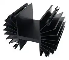
490-6K
HEAT SINK
⚠️ Reference pricing provided. In case of supply shortages, we will connect you with our trusted procurement partners to ensure your project's continuity.
- Manufacturer: WAKEFIELD THERMAL
- Product type: Natural Convection Heat Sinks
- Heat Sink Material: Aluminium
- Thermal Resistance: 0.3°C/W
- External Width - Metric: 235mm
- External Height - Metric: 171.5mm
- External Length - Metric: 152mm
- External Width - Imperial: 9.3"
- External Height - Imperial: 6.8"
- External Length - Imperial: 6"
| Delivery and price | |
|---|---|
| Units per pack | 1 |
| Price | 124.85 € |
| Current stock | 10+ |
| Lead time | 30 days |
Datasheet

## **EXTRUDED HEAT SINKS FOR POWER SEMICONDUCTORS**

## **Low-Profile Heat Sinks for All Metal-Case Power Semiconductors**

**621/623 SERIES**

|**621/623 SERIES**|**Low-Profile Heat Sinks for All Metal-Case Power Semiconductors**<br>**621/623 SERIES**|**Low-Profile Heat Sinks for All Metal-Case Power Semiconductors**|**Low-Profile Heat Sinks for All Metal-Case Power Semiconductors**|**Low-Profile Heat Sinks for All Metal-Case Power Semiconductors**|**Low-Profile Heat Sinks for All Metal-Case Power Semiconductors**|_TO-3_|
|---|---|---|---|---|---|---|
||**Footprint**|||**Thermal Performance at Typical Load**|**Thermal Performance at Typical Load**||
|**Standard**|**Dimensions**|**Height**|**Mounting**|**Natural**|**Forced**|**Weight**|
|**P/N**|**in.(mm)**|**in.(mm)**|**Hole Pattern**|**Convection**|**Convection**|**lbs.(grams)**|
|621A|4.750 (120.6) x 1.500 (38.1)|0.461 (11.7)|(1) TO-3|75°C @ 15W|2.0°C/W @ 250 LFM|0.1000 (45.36)|
|621K|4.750 (120.6) x 1.500 (38.1)|0.461 (11.7)|None|75°C @ 15W|2.0°C/W @ 250 LFM|0.1000 (45.36)|
|623A|4.750 (120.6) x 3.000 (76.2)|0.461 (11.7)|(1) TO-3|52°C @ 15W|1.5°C/W @ 250 LFM|0.2100 (95.26)|
|623K|4.750(120.6)x 3.000(76.2)|0.461(11.7)|None|52°C @ 15W|1.5°C/W @ 250 LFM|0.210O(95.26)|


A general purpose yet efficient heat dissipator for TO-3 and virtually all other styles of metal case power semiconductor package types, the 621 and 623 Series low-profile flat back heat sinks find a wide variety of applications. The central channel between fins measures 1.300 in. (33.0) (min.) in

width, accommodating many types of packages. Mounting hole pattern "A" is predrilled for the standard TO-3 package. Material: Aluminum Alloy, Black Anodized.

## **MECHANICAL DIMENSIONS**

**==> picture [305 x 61] intentionally omitted <==**

**----- Start of picture text -----**<br>
621 AND 623 SERIES (EXTRUSION PROFILE 1327)<br>NATURAL AND FORCED<br>CONVECTION CHARACTERISTICS<br>mre 4 00<br>Loa<br>SEMICONDUCTOR MOUNTING HOLES<br>A K<br>eit<br>if ann Bea um if<br>**----- End of picture text -----**<br>


**==> picture [63 x 8] intentionally omitted <==**

**----- Start of picture text -----**<br>
Dimensions: in. (mm)<br>**----- End of picture text -----**<br>


## **Compact Heat Sinks for Dual Stud-Mounted Semiconductor Cases**

## **301/302/303 SERIES**

|**301/302/303 SERIES**|**301/302/303 SERIES**|**Compact Heat Sinks for Dual Stud-Mounted Semiconductor Cases**|**Compact Heat Sinks for Dual Stud-Mounted Semiconductor Cases**|**Compact Heat Sinks for Dual Stud-Mounted Semiconductor Cases**|**Compact Heat Sinks for Dual Stud-Mounted Semiconductor Cases**|**Compact Heat Sinks for Dual Stud-Mounted Semiconductor Cases**|**Compact Heat Sinks for Dual Stud-Mounted Semiconductor Cases**|_STUD-MOUNT_|
|---|---|---|---|---|---|---|---|---|
||**Outline**||||**Mounting**|**Thermal Performance at Typical Load**|||
|**Standard**|**Dimensions**||**Length “A”**||**Hole (s)**|**Natural**|**Forced**|**Weight**|
|**P/N**|**in. (mm)**||**in. (mm)**||**Pattern and Number**|**Convection**|**Convection**|**lbs. (grams)**|
|301K|2.000 (50.8) x 2.000 (50.8)|2.000 (50.8) x 2.000 (50.8)|0.750 (19.1)||None|70°C @ 15W|2.5°C/W @ 250 LFM|0.0580 (26.31)|
|301M|2.000 (50.8) x 2.000 (50.8)|2.000 (50.8) x 2.000 (50.8)|0.750 (19.1)|(1) 10-32UNF, 0.625 in. thread depth|(1) 10-32UNF, 0.625 in. thread depth|70°C @ 15W|2.5°C/W @ 250 LFM|0.0580 (26.31)|
|301N|2.000 (50.8) x 2.000 (50.8)|2.000 (50.8) x 2.000 (50.8)|0.750 (19.1)|(1)|1⁄4-28UNF, 0.625 in. thread depth|70°C @ 15W|2.5°C/W @ 250 LFM|0.0580 (26.31)|
|302M|2.000 (50.8) x 2.000 (50.8)|2.000 (50.8) x 2.000 (50.8)|1.500 (38.1)|(1) 10-32UNF, 0.625 in. thread depth|(1) 10-32UNF, 0.625 in. thread depth|50°C @ 15W|1.8°C/W @ 250 LFM|0.1330 (60.33)|
|302MM|2.000 (50.8) x 2.000 (50.8)|2.000 (50.8) x 2.000 (50.8)|1.500 (38.1)|(2) 10-32UNF, 0.625 in. thread depth|(2) 10-32UNF, 0.625 in. thread depth|50°C @ 15W|1.8°C/W @ 250 LFM|0.1330 (6033)|
|302N|2.000 (50.8) x 2.000 (50.8)|2.000 (50.8) x 2.000 (50.8)|1.500 (38.1)|(1)|1⁄4-28UNF, 0.625 in. thread depth|5O°C @ 15W|1.8°C/W @ 250 LFM|0.1330 (60.33)|
|302NN|2.000 (50.8) x 2.000 (50.8)|2.000 (50.8) x 2.000 (50.8)|1.500 (38.1)|(2)|1⁄4-28UNF, 0.625 in. thread depth|50°C @ 15W|1.8°C/W @ 250 LFM|0.1330 (60.33)|
|303M|2.000 (50.8) x 2.000 (50.8)|2.000 (50.8) x 2.000 (50.8)|3.000 (76.2)|(1) 10-32UNF, 0.625 in. thread depth|(1) 10-32UNF, 0.625 in. thread depth|37°C @ 15W|1.3°C/W @ 250 LFM|0.2680 (121.56)|
|303MM|2.000 (50.8) x 2.000 (50.8)|2.000 (50.8) x 2.000 (50.8)|3.000 (76.2)|(2) 10-32UNF, 0.625 in. thread depth|(2) 10-32UNF, 0.625 in. thread depth|37°C @ 15W|1.3°C/W @ 250 LFM|0.2680 (121.56)|
|303N|2.000 (50.8) x 2.000 (50.8)|2.000 (50.8) x 2.000 (50.8)|3.000 (76.2)|(1)|1⁄4-28UNF, 0.625 in. thread depth|37°C @ 15W|1.3°C/W @ 250 LFM|0.2680 (121.56)|
|303NN|2.000(50.8)x 2.000|x 2.000(50.8)|3.000(76.2)|(2)|1⁄4-28UNF,0.625 in. thread depth|37°C @ 15W|1.3°C/W @ 250 LFM|0.2680(121.56)|


The large fin area in minimum total volume provided by the radial design of the 301/302/303 Series offers maximum heat transfer efficiency in natural convection. All types are available with one tapped mounting hole for rectifiers and other stud-mounting semiconductors; the

302 and 303 Series offer maximum cost savings with dual mounting locations (“MM” and “NN” mounting hole patterns) for two stud-mount devices. Material: Aluminum Alloy, Black Anodized.

## **MECHANICAL DIMENSIONS**

**==> picture [463 x 91] intentionally omitted <==**

**----- Start of picture text -----**<br>
BOL Cee CoDeS NATURAL AND FORCED<br>CONVECTION CHARACTERISTICS<br>melt ee<br>SEMICONDUCTOR MOUNTING HOLES<br>[rreor] oF aNCCuE “TF a amit+ er ~ al oe ee<br>K M N<br>|__| ‘ nate = Ta 5 : eae<br> ‘| ’ ma | } tay ial vane i : ‘are eo<br>302 AND 303 SERIES<br>SERIES<br>301<br>302<br>301 SERIES 303<br>**----- End of picture text -----**<br>


**==> picture [63 x 8] intentionally omitted <==**

**----- Start of picture text -----**<br>
Dimensions: in. (mm)<br>**----- End of picture text -----**<br>


**45**

**Extruded Heat Sinks**

## **EXTRUDED HEAT SINKS FOR POWER SEMICONDUCTORS**

## **Double-Surface Heat Sinks for TO-3 Case Styles**

## **401 & 403 SERIES**

|**401 & 403 SERIES**|**401 & 403 SERIES**|**Double-Surface Heat Sinks for TO-3 Case Styles**|**Double-Surface Heat Sinks for TO-3 Case Styles**|**Double-Surface Heat Sinks for TO-3 Case Styles**|**Double-Surface Heat Sinks for TO-3 Case Styles**||_TO-3; Stud-Mount_|
|---|---|---|---|---|---|---|---|
|**Standard**|**Width**|**Overall Dimensions**|**Height**|**Semiconductor**|**Thermal Performance at Typical Load**||**Weight**|
|**P/N**|**in. (mm)**|**in. (mm)**|**in. (mm)**|**Mounting Hole Pattem**|**Natural Convection**|**Forced Convection**|**lbs. (grams)**|
|401A|4.750 (120.7)|1.500 (38.1)|1.250 (31.8)|(1) TO-3|80°C @ 30W|1.5°C/W @ 250 LFM|0.1500 (68.04)|
|401F|4.750 (120.7)|1.500 (38.1)|1.250 (31.8)|0.270 in. (6.9)-Dia Hole|80°C @ 30W|1.5°C/W @ 250 LFM|0.1500 (68.04)|
|401K|4.750 (120.7)|1.500 (38.1)|1.250 (31.8)|None|80°C @ 30W|1.5°C/W @ 250 LFM|0.1500 (68.04)|
|403A|4.750 (120.7)|3.000 (76.2)|1.250 (31.8)|(1) TO-3|55°C @ 30W|0.9°C/W @ 250 LFM|0.3500 (158.76)|
|403F|4.750 (120.7)|3.000 (76.2)|1.250 (31.8)|0.270 in. (6.9)-Dia Hole|55°C @ 30W|0.9°C/W @ 250 LFM|0.3500 (158.76|
|403K|4.750(120.7)|3.000(76.2)|1.250(31.8)|None|55°C @ 30W|0.9°C/W @ 250 LFM|0.3500(158.76)|


With fins oriented vertically in cabinet sidewall applications, 401 and 403 Series heat sinks are recommended for critical space applications where maximum heat dissipation is required for high-power TO-3 case styles. Forced convection performance is also exemplary with these double surface fin types. Semiconductor mounting hole style “F” offers a single centered 0.270

in. (6.9)-diameter mounting hole (with a 0.750 in. (19.1)-diameter area free of anodize) for mounting stud-type diodes and rectifiers. Hole pattem “V" available upon request. Material: Aluminum Alloy, Black Anodized.

**==> picture [484 x 165] intentionally omitted <==**

**----- Start of picture text -----**<br>
MECHANICAL DIMENSIONS NATURAL AND FORCED<br>uns 18 L, ‘in CONVECTION CHARACTERISTICS<br>evn Ti] nos) oe 0.085 ma<br>Yona oT tat | pak [yes- AMF MELOY (LPR)<br>4s mn| . 1s aaooan<br>TELA 1 i Pet .® 7" a ra?<br>|| nrg E-L | qa u= Suei pe25<br>S| HES<br>403 SERIES 401 SERIES<br>rep) | - sho cee] brad ae DAS:<br>Py te WO<br>Dimensions: in. (mm) SEMICONDUCTOR MOUNTING HOLES aie tasPOSER C4SSIFosATIONans(ATTY<br>A is F ara K <—e V ‘ob in<br>non- | Ooasr eu au (Hilaed oF mm| La<br>401 AND 403 SERIES<br>(EXTRUSION<br>me te yt|| ae wns teeth PROFILE 1024)<br>**----- End of picture text -----**<br>


## **413/421/423 SERIES**

## **Low-Height Double-Surface Heat Sinks for TO-3 Case Styles and Diodes**

_TO-3; DO-5; Stud-Mount_

|||**Nominal Dimensions**||||||
|---|---|---|---|---|---|---|---|
|**Standard**|**Width**|**Length**|**Height “A”**|**Semiconductor**|**Thermal Performance at Typical Load**||**Weight**|
|**P/N**|**in. (mm)**|**in. (mm)**|**in. (mm)**|**Mounting Hole Pattern**|**Natural Convection**|**Forced Convection**|**lbs. (grams)**|
|413A|4.750 (120.7)|3.000 (76.2)|1.875 (47.6)|(1) TO-3|72°C @ 50W|0.85°C/W @ 250 LFM|0.6300 (285.77)|
|413F|4.750 (120.7)|3.000 (76.2)|1.875 (47.6)|0.270 in. (6.9)-Dia Hole|72°C @ 50W|0.85°C/W @ 250 LFM|0.6300 (285.77)|
|413K|4.750 (120.7)|3.000 (76.2)|1.875 (47.6)|None|72°C @ 50W|0.85°C/W @ 250 LFM|0.6300 (285.77)|
|421A|4.750 (120.7)|3.000 (76.2)|2.625 (66.7)|(1) TO-3|58°C @ 50W|0.7°C/W @ 250 LFM|0.6300 (285.77)|
|421F|4.750 (120.7)|3.000 (76.2)|2.625 (66.7)|0.270 in. (6.9)-Dia Hole|58°C @ 50W|0.7°C/W @ 250 LFM|0.6300 (285.77)|
|421K|4.750 (120.7)|3.000 (76.2)|2.625 (66.7)|None|58°C @ 50W|0.7°C/W @ 250 LFM|0.6300 (285.77)|
|423A|4.750 (120.7)|5.500 (140.2)|2.625 (66.7)|(1) TO-3|47°C @ 50W|0.5°C/W @ 250 LFM|1.1700 (530.71)|
|423K|4.750(120.7)|5.500(140.2)|2.625(66.7)|None|47°C @ 50W|0.5°C/W @ 250 LFM|1.1700(530.71)|


Space-saving double surface 413, 421, and 423 Series utilize finned surface area on both sides of the power semiconductor mounting surface to provide maximum heat dissipation in a compact profile. Ready to install on popular power components in natural and forced convection applications. Apply Wake-

field Type 126 silicone-free thermal compound or Wakefield DeltaPad™interface materials for maximum performance. Material: Aluminum Alloy, Black Anodized.

## **MECHANICAL DIMENSIONS**

**==> picture [505 x 141] intentionally omitted <==**

**----- Start of picture text -----**<br>
NATURAL AND FORCED<br>om pA ne | cm CONVECTION CHARACTERISTICS<br>(eae |™ ae | nim ditn A VELOSTY9h Pi<br>1 i aLE an ae | - ee: De atuee ee<br>423 SERIES<br>oan (EXTRUSION413 SERIES iro] aga ian ¥ (EXTRUSION PROFILE 1025) ince _ pga i. ms, | Bee ae<br>PROFILE 2276)<br>(mz) ay me jz AEF dann ial |e emt<br>(EXTRUSION421 SERIES SEMICONDUCTOR MOUNTING HOLES . cai —<br>PROFILE 1025) A _ F = K V moa) HAs<br>ca | (ra — Le ee<br>SERIES<br>413 ston na a et au & —" i aE POSVIF ERMAN (NTT<br>421 24 eden [ESE [RS | gun ce ie<br>Be rye ie ir a Or axe 4<br>Dimensions: in. (mm) ah a ~ Bena<br>**----- End of picture text -----**<br>


**46**

## **EXTRUDED HEAT SINKS FOR POWER SEMICONDUCTORS**

|**431 & 433 SERIES**|**431 & 433 SERIES**|**High-Performance Heat Sinks for 30-100W Metal Power Semiconductors**|**High-Performance Heat Sinks for 30-100W Metal Power Semiconductors**|**High-Performance Heat Sinks for 30-100W Metal Power Semiconductors**|**High-Performance Heat Sinks for 30-100W Metal Power Semiconductors**|**High-Performance Heat Sinks for 30-100W Metal Power Semiconductors**|_TO-3; Stud-Mount_|
|---|---|---|---|---|---|---|---|
||**Nominal Dimensions**|||||||
|**Standard**|**Width**|**Length “A”**|**Height**|**Semiconductor**|**Thermal Performance at Typical Load**||**Weight**|
|**P/N**|**in.(mm)**|**in.(mm)**|**in.(mm)**|**Mounting Hole Pattern**|**Natural Convection**|**Forced Convection**|**lbs.(grams)**|
|431K|4.750 (120.7)|3.000 (76.2)|3.000 (76.2)|None|55°C @ 5OW|0.40°C/W @ 250 LFM|0.7800 (353.81)|
|433K|4.750(120.7)|5.500(139.7)|3.000(76.2)|None|42°C @ 5OW|0.28°C/W @ 250 LFM|1.4900(675.86)|


Need maximum heat dissipation from a TO-3 rectifier heat sink in minimum space? The Wakefield 431 and 433 Series center chan-

nel double-surface heat sinks offer the highest performance-to-weight ratio for minimum volume occupied for TO-3, diode, and stud-mount metal power semiconductors in the 30- to

100-watt operating range. Additional interface resistance reduction for maximized overall performance can be achieved with proper application of Wakefield Type 126 silicone-free thermal compound. Material: Aluminum Alloy, Black Anodized.

**MECHANICAL DIMENSIONS** piri **SERIES** Cs **CONVECTION CHARACTERISTICSNATURAL AND FORCED** [PaaSLo I ye _' a : am: fl **431433** Les]Cea | POOyis gt TO LateeALLEDC ATS ij - **SEMICONDUCTOR** L **MOUNTING HOLE** 15 um 45 au iso . iy it1 b3ee **431 AND 433 SEK** F aret **RIES** aon itn **(EXTRUSION PRO-** ie ‘na - r _ **FILE 2726)** ae a! uty —_—F a “* ft inne | **Dimensions: in. (mm)** ADE! ST PRATT **435 SERIES Lightweight Quadruple Mount Heat Sink for TO-3 Case Styles** _TO-3_ **Nominal Dimensions Standard Width Length Height Semiconductor Thermal Performance at Typical Load Weight P/N in. (mm) in. (mm) in. (mm) Mounting Hole Pattern Natural Convection Forced Convection lbs. (grams)** 435AAAA 4.250 (108.0) 5.500 (139.7) 4.300 (109.2) (4) TO-3 37°C @ 50W 0.38°C/W @ 250 LFM 1.1500 (521.64) 54°C @ 80W 0.24°C/W @ 600 LFM

This lightweight high-performance heat sink is designed to mount and cool efficiently one to four TO-3 style metal case power semiconductors. The Type 435AAAA is the standard configuration available from stock, predrilled for mounting four TO-3 style devices. Increased performance can be achieved with the proper

selection and installation of a Wakefield Type 175 DeltaPad Kapton™interface material for each power semiconductor or, for maximum reduction of case-to-sink interface loss, the application of Wakefield Type 126 silicone-free thermal compound. Material: Aluminum Alloy, Black Anodized.

**==> picture [90 x 7] intentionally omitted <==**

**----- Start of picture text -----**<br>
MECHANICAL DIMENSIONS<br>**----- End of picture text -----**<br>


**==> picture [63 x 7] intentionally omitted <==**

**----- Start of picture text -----**<br>
Dimensions: in. (mm)<br>**----- End of picture text -----**<br>


**==> picture [240 x 106] intentionally omitted <==**

**----- Start of picture text -----**<br>
NATURAL AND FORCED<br>CONVECTION CHARACTERISTICS<br>oR ELOCITS fire<br>. MOUNTING HOLESSEMICONDUCTOR Zz a egty a APitreytETTteae<br>AAAA<br>ai 1 } pees<br>B By et de<br>a 4 oe we ass = rr<br>im ah . ii = Lt a<br>r 435 SERIES wetrey ge? zee ' a8orSee ee ee i n<br>(EXTRUSION ee ae Ble A Dende Pede ela<br>PROFILE 4226) aE<br>**----- End of picture text -----**<br>


## **High-Performance Natural Convection Heat Sinks for Rectifiers and Diodes**

**==> picture [49 x 9] intentionally omitted <==**

**----- Start of picture text -----**<br>
441 SERIES<br>**----- End of picture text -----**<br>


|**441 SERIES**|**441 SERIES**|**High-Performance Natural Convection Heat Sinks for Rectifiers and Diodes**|**High-Performance Natural Convection Heat Sinks for Rectifiers and Diodes**|**High-Performance Natural Convection Heat Sinks for Rectifiers and Diodes**|**High-Performance Natural Convection Heat Sinks for Rectifiers and Diodes**|**High-Performance Natural Convection Heat Sinks for Rectifiers and Diodes**|**High-Performance Natural Convection Heat Sinks for Rectifiers and Diodes**|_Stud-Mount_|
|---|---|---|---|---|---|---|---|---|
|||**Nominal Dimensions**|||||||
|**Standard**||**Width**|**Length**|**Height**|**Semiconductor**|**Thermal Performance at Typical Load**||**Weight**|
|**P/N**|**in.(mm)**||**in.(mm)**|**in.(mm)**|**Mounting Hole Pattern**|**Natural Convection**|**Forced Convection**|**lbs.(grams)**|
|441K|4.750 (120.7)||5.500 (139.7)|4.500 (114.3)|None|34°C @ SOW|0.30°C/W @ 250 LFM|1.9700 (893.59)|
|||||||47°C @ 80W|0.19°C/W @ 600 LFM||


tion environment, the 441K Type will achieve thermal resistance of 0.18°C/W (sink to ambient) at 1000 LFM. Supplied with no predrilled device mounting hole pattern. Material: Aluminum Alloy, Black Anodized.

Designed for vertical mounting within a power supply enclosure or equipment cabinet without forced airflow available. This Wakefield 441 Series heat sink will dissipate up to 100 watts efficiently in natural convection with a maximum 55°C heat sink temperature rise above ambient. When applied in a forced convec-

> **Dimensions: in. (mm)** ee

**==> picture [231 x 58] intentionally omitted <==**

**----- Start of picture text -----**<br>
MECHANICAL DIMENSIONS NATURAL AND FORCED<br>CONVECTION CHARACTERISTICS<br>SEMICONDUCTORMOUNTING HOLEK Tecerr |H| SUFLLaeSeLOTTHeee aeeLFWa eeA a |<br>441 SERIES<br>(EXTRUSION Ei Pas<br>PROFILE 1273) ae | a a<br>**----- End of picture text -----**<br>


**47**

**Extruded Heat Sinks**

## **EXTRUDED HEAT SINKS FOR POWER SEMICONDUCTORS**

**==> picture [342 x 10] intentionally omitted <==**

**----- Start of picture text -----**<br>
465 & 476 SERIES High-Power Heat Sinks for Medium Hex-Type Rectifiers and Diodes<br>**----- End of picture text -----**<br>


|**465 & 476 SERIES**|**465 & 476 SERIES**|**High-Power Heat Sinks for Medium Hex-Type Rectifiers and Diodes**|**High-Power Heat Sinks for Medium Hex-Type Rectifiers and Diodes**|**High-Power Heat Sinks for Medium Hex-Type Rectifiers and Diodes**|**High-Power Heat Sinks for Medium Hex-Type Rectifiers and Diodes**|**High-Power Heat Sinks for Medium Hex-Type Rectifiers and Diodes**|**High-Power Heat Sinks for Medium Hex-Type Rectifiers and Diodes**||
|---|---|---|---|---|---|---|---|---|
|**465 & 476 SERIES**|**465 & 476 SERIES**|**High-Power Heat Sinks for Medium Hex-Type Rectifiers and Diodes**|**High-Power Heat Sinks for Medium Hex-Type Rectifiers and Diodes**|**High-Power Heat Sinks for Medium Hex-Type Rectifiers and Diodes**|**High-Power Heat Sinks for Medium Hex-Type Rectifiers and Diodes**|**High-Power Heat Sinks for Medium Hex-Type Rectifiers and Diodes**|**High-Power Heat Sinks for Medium Hex-Type Rectifiers and Diodes**|_Stud-Mount_|
||**Nominal Dimensions**||||||||
|**Standard**|**Width**|**Length**|**Height**|**Hex Style**|**Mounting**|**Thermal Performance at Typical Load**||**Weight**|
|**P/N**|**in. (mm)**|**in. (mm)**|**in. (mm)**|**Type**|**Hole Pattern**|**Natural Convection**|**Forced Convection**|**lbs. (grams)**|
|465K|4.000 (101.6)|5.000 (127.0)|4.000 (101.6)|1.060 in. Hex|None|38°C @ 5OW|0.27°C/W @ 500 LFM|1.9300 (875.45)|
|476K|5.000 (127.0)|6.000 (152.4)|5.000 (127.0)|1.250 in. Hex|None|25°C @ 5OW|0.19°C/W @ 500 LFM|2.8200 (1279.15)|
|476W|5.000 (127.0)|6.000 (152.4)|5.000 (127.0)|1.250 in. Hex|0.765 in.|25°C @ 5OW|0.19°C/W @ 500 LFM|2.8000 (1270.08)|
||||||(19.4) Dia.||||
||||||Center Mount||||


Wakefield Engineering has designed four standard heat sink types for ease of installation and signed for 1.060 in. Hex (465 Type) and 1.250 in. Hex (476 Type). The 476W Type is available efficient heat dissipation for industry standard hex-type rectifiers and similar stud-mount predrilled for an 0.765 in. (19.4) dia, mounting hole, Material: Aluminum Alloy, Black anodized. power devices: 465, 476, 486, and 489 Series. The 465 and 476 Series shown here are de-

**==> picture [90 x 7] intentionally omitted <==**

**----- Start of picture text -----**<br>
MECHANICAL DIMENSIONS<br>**----- End of picture text -----**<br>


**==> picture [445 x 106] intentionally omitted <==**

**----- Start of picture text -----**<br>
I axa! | (Th a 465 SERIES (EXTRUSION NATURAL AND FORCED<br>fa Fr (zr) as PROFILE 1244) CONVECTION CHARACTERISTICS<br>Pepi 476 SERIES (EXTRUSION | Pan AA WELIOCITY fF<br>an TERS PROFILE 1245) L Pee eeee<br>cL r,<br>K W Lia = oo<br>are maf oe aapgcs * +L  =f—-p-Cry+<br>SEMICONDUCTOR cdg AMDOE | al i<br>MOUNTING HOLES<br>OLED “Sim fe et<br>| BIER eS or<br>Dimensions: in. (mm) so“fe : | FSS* :* 7 iao<br>**----- End of picture text -----**<br>


## **486 & 489 SERIES**

## **Heat Sinks for High-Power Hex-Type Rectifiers and Diodes**

_Stud-Mount_

|||**Nominal Dimensions**|||||||
|---|---|---|---|---|---|---|---|---|
|**Standard**|**Width**|**Length**|**Height**|**Hex Style**|**Mounting**|**Thermal Performance at Typical Load**||**Weight**|
|**P/N**|**in. (mm)**|**in. (mm)**|**in. (mm)**|**Type**|**Hole Pattern**|**Natural Convection**|**Forced Convection**|**lbs. (grams)**|
|486K|6.250 (158.8)|6.000 (152.4)|6.250 (158.8)|1.750 in. Hex|None|24°C @ 50W|0.20°C/W @ 250 LFM|4.2100 (1909.66)|
|||||||86°C @ 250W|0.13°C/W @ 500 LFM||
|489K|6.250 (158.8)|9.000 (228.6)|6.250 (158.8)|1.750 in. Hex|None|19°C @ 50W|0.15°C/W @ 250 LFM|6.1400 (2785.10)|
|||||||75°C @ 250W|0.10°C/W @ 500 LFM||


These two heat sink types accept industry standard 1.750 in. (44.5) hex-type devices for mounting and efficient heat dissipation. Each type is provided with a 1.750 in. (44.5) x 2.000

in. (50.8) area on the semiconductor base mounting surface which is free of anodize. Material: Aluminum Alloy, Black Anodized.

**==> picture [470 x 189] intentionally omitted <==**

**----- Start of picture text -----**<br>
MECHANICAL DIMENSIONS SEMICONDUCTOR<br>MOUNTING HOLE K<br>fui J a) ste a 7 ai<br>ay ml6, {) Od TP a icy a | * 4 LAMM<br>( a Ee ee WO HOLES<br>= 7 —)__ sARA Fat OF auooae<br>1 ee : ae £ THE: SI ML<br>NATURAL AND FORCED<br>(aa)280 201 HEDez ST|| | “8bia ‘ CONVECTION CHARACTERISTICS AIA WELOMCITY (LF<br>q<br>| ' pana 200 Joei J nee euEf eea a<br>[HL man my ee i an,<br>ar | ae Be Fi<br>nsenn Ebr | az CF = oa ral<br>SERIES a 1h Ba a 486 AND 489 SERIES (EX-TRUSION 5aee: ift<br>Dimensions: in. (mm) 486489 OOO“* v PROFILE 1541) A—— ae<br>**----- End of picture text -----**<br>


**48**

## **EXTRUDED HEAT SINKS FOR POWER SEMICONDUCTORS**

|**King Size Heat Sinks for High-Power Rectifiers**<br>**490 SERIES**|**King Size Heat Sinks for High-Power Rectifiers**<br>**490 SERIES**|**King Size Heat Sinks for High-Power Rectifiers**|**King Size Heat Sinks for High-Power Rectifiers**|**King Size Heat Sinks for High-Power Rectifiers**|||_GENERAL PURPOSE_|
|---|---|---|---|---|---|---|---|
|||**Nominal Dimensions**||||||
|**Standard**|**Width**|**Length “A”**|**Height**|**Semiconductor**|**Thermal Performance at Typical Load**||**Weight**|
|**P/N**|**in. (mm)**|**in. (mm)**|**in. (mm)**|**Mounting Hole Pattern**|**Natural Convection**|**Forced Convection**|**lbs. (grams)**|
|490-35K|9.250 (235.0)|3.500 (88.9)|6.750 (171.5)|None|84°C @ 20OW|0.18°C/W @ 600 LFM|3.2400(1469.66)|
|490-6K|9.250 (235.0)|6.000 (152.4)|6.750 (171.5)|None|60°C @ 20OW|0.13°C/W @ 600 LFM|5.4700(2481.19)|
|490-12K|9.250(235.0)|12.000(304.8)|6.750(171.5)|None|45°C @ 20OW|0.09°C/W @ 600 LFM|10.6200(4817.23)|


The 490 Series can be used to mount a single high-power rectifier or a grouping of smaller power devices. The semiconductor device mounting surface is free of anodize on the entire surface on one side only; finish overall is black anodize. Use Type 109 mounting brackets (see accessories section) for mounting to enclosure wall and for electrical isolation. The anodize-

free mounting surface is milled for maximum contact area. The 490 Series Can also be drilled for mounting and cooling IGBTs and other isolated power modules. Material: Aluminum Alloy, Black Anodized.

|**MECHANICAL DIMENSIONS**|||||||**SEMICONDUCTOR**<br>**MOUNTING HOLE**|**NATURAL AND FORCED**<br>**CONVECTION CHARACTERISTICS**|**NATURAL AND FORCED**<br>**CONVECTION CHARACTERISTICS**|**NATURAL AND FORCED**<br>**CONVECTION CHARACTERISTICS**|
|---|---|---|---|---|---|---|---|---|---|---|
|**490 SERIES**<br>**(EXTRUSION PROFILE 2131)**|=e<br>ae|vi<br>ue<br>|e||Lie|pits|||nes<br>ge|eee<br>|<br>a|el<br>||
|**Dimensions: in. (mm)**|LF|‘||Tx||7||ze|ia||


## **PERFORMANCE, LOW PROFILE HEAT SINKS FOR POWER MODULES & IGBT’S**

## **394, 395, 396 SERIES**

|**394, 395, 396 SERIES**|**394, 395, 396 SERIES**|||||||
|---|---|---|---|---|---|---|---|
|||||||**Thermal Resistance at Typical Load**|**Thermal Resistance at Typical Load**|
||**Overall Dimensions: in. (mm)**|||**Device Base**||**Natural**|**Forced**|
|**Standard**|**Length**|**Height**|**Width**|**Mounting Area**|**Base Mounting**|**Convection (Øsa)(1)**|**Convection (Øsa)**|
|**P/N**|**in. (mm)**|**in. (mm)**|**in. (mm)**|**(mm)**|**Holes**|**(°C/W)**|**(°C/W @ 500 LFM)**|
|394-1AB|3.000 (76.2)|1.500 (38.1)|5.000 (127.0)|101 x 76|4|1.85|0.90|
|394-2AB|5.500 (139.7)|1.500 (38.1)|5.000 (127.0)|101 x 139|6|1.51|0.60|
|395-1AB|3.000 (76.2)|2.500 (63.5)|5.000 (127.0)|50 x 76|4|1.10|0.50|
|395-2AB|5.500 (139.7)|2.500 (63.5)|5.000 (127.0)|50 x 139|6|0.90|0.32|
|396-1AB|3.000 (76.2)|1.380 (35.1)|5.000 (127.0)|50 x 76|4|1.85|1.07|
|396-2AB|5.500(139.7)|1.380(35.1)|5.000(127.0)|50 x 139|6|1.51|0.64|
|**Note:**_1.Thermal resistance values shown are for black anodized finish at 50°C rise above ambient._|_1.Thermal resistance values shown are for black anodized finish at 50°C rise above ambient._|||||||


**==> picture [476 x 292] intentionally omitted <==**

**----- Start of picture text -----**<br>
MECHANICAL DIMENSIONS NATURAL AND FORCED<br>CONVECTION CHARACTERISTICS<br>394 SERIES<br>(EXTRUSION PROFILE 7332)<br>-—a—7 . pal ceubmaYnes sua? - “<br>NATURAL AND FORCED<br>iL | | | =e ~ ime 4 CONVECTION CHARACTERISTICS 4 ee a om<br>395 SERIES<br>(EXTRUSION PROFILE 7330) te i oI r ah wl ue TT aie<br>| tm en jane eral<br>a OU EE ie | } | ‘ i. TT geet arr = in<br>goreSeer esey| eee r =ine AF _ [oCiPittiss:  aaap =n1,|<br>NATURAL AND FORCED<br>CONVECTION CHARACTERISTICS<br>in I mer . ast 4 7 —— 7=<br>396 SERIES<br>(EXTRUSION PROFILE 7331) rxmill| TI1 Ba.1 gp Repsa el) peesee<br>iF er i MeSe cnacos<br>I, | | L Loge J i * pet tee tt<br>ey ae t ~- iim fe Fe Se<br>Dimensions: in. (mm)<br>**----- End of picture text -----**<br>


**49**

**Extruded Heat Sinks**

## **EXTRUDED HEAT SINKS FOR DC/DC CONVERTERS**

## **Heat Sinks for “Full-Brick” DC/DC Converters**

|||**Heat Sinks for “Full-Brick” DC/DC Converters**|**Heat Sinks for “Full-Brick” DC/DC Converters**|**Heat Sinks for “Full-Brick” DC/DC Converters**|||
|---|---|---|---|---|---|---|
|**Standard**<br>**P/N**<br>557-140AB<br>558-75AB<br>**SERIES 557, 558 & 559**|4.60 (116.8) x 2.40 (61.0)<br>2.40 (61.0) x 4.60 (116.8)<br>**SERIES 557, 558 & 559**|**Heat Sinks for “Full-Brick” DC/DC Converters**<br>**Footprint**<br>**Dimensions**<br>**in.(mm)**<br>4.60 (116.8) x 2.40 (61.0)<br>2.40 (61.0) x 4.60 (116.8)<br>**SERIES 557, 558 & 559**|**Heat Sinks for “Full-Brick” DC/DC Converters**<br>**Height**<br>**in.(mm)**<br>1.40 (35.6)<br>0.75 (19.1)|**Heat Sinks for “Full-Brick” DC/DC Converters**<br>**Fin**<br>**Number**<br>**Orientation**<br>**of Fins**<br>Horizontal<br>6<br>Vertical<br>16|**Forced Convection**<br>**Thermal Resistance**<br>**at 300 ft/min(C/W)**<br>1.3<br>1.8|**Natural Convection**<br>**Power Dissipation (Watts)**<br>**40°C Rise Heat Sink**<br>**to Ambient**<br>14<br>12<br>_TO-220 and TO-218_|
|559-50AB|2.40|2.40(61.0)x 4.60(116.8)|0.50(12.7)|Vertical<br>27|2.2|10|


Material: Aluminum, Black Anodized

• Standard mounting hole pattern mates with Vicor DC/DC converters. • Aluminum extruded fin construction keeps DC/DC converter modules cool in both forced and natural convection applications. • Three fin heights, two flow direction options. • Black anodized finish standard.

- Integral thermal interface pad option eliminates need to order and install pad separately.

- Ordering a single part number with the hardware kit option provides everything necessary to keep your converter cool.

## **MECHANICAL DIMENSIONS**

**==> picture [319 x 125] intentionally omitted <==**

**----- Start of picture text -----**<br>
557 SERIES<br>PRODUCT DESIGNATION DIMENSIONS<br>SERIES 557 -140 - AB - MS4<br>S4 = DELTALINK IV<br>BLANK = NO THERMAL PAD<br>2 . 400 [60 . 96]<br>e100<br>M = M3 X 8mm PHILLIPS HD SEM SCREW,<br>WITH CAPTIVE WASHER<br>H = 4 - 40 X 5/16" PHILLIPS HD SEM SCREW,<br>BLANKWITH  = NOCAPTIVE FASTENERWASHER OPTION - 150 [3.81] 4<br>. 500<br>Dimensions: in. (mm)<br>**----- End of picture text -----**<br>


## **MECHANICAL DIMENSIONS**

**==> picture [115 x 159] intentionally omitted <==**

**----- Start of picture text -----**<br>
PRODUCT DESIGNATION<br>SERIES<br> 558 - 75 - AB -  MS4<br>Dimensions: in. (mm)<br>**----- End of picture text -----**<br>


**==> picture [39 x 15] intentionally omitted <==**

**----- Start of picture text -----**<br>
558 SERIES<br>DIMENSIONS<br>**----- End of picture text -----**<br>


## **MECHANICAL DIMENSIONS**

**==> picture [311 x 161] intentionally omitted <==**

**----- Start of picture text -----**<br>
559 SERIES<br>DIMENSIONS<br>PRODUCT DESIGNATION<br>SERIES<br> 559 - 50 - AB - MS4<br>$4 = DELTALINK IV<br>BLANK = NO THERMAL PAD 2.400 [60.96]<br>2<br>T = 9X Smm PHILLIPS HD SEM SCREW,<br>H ee<br>= 4-40 X 5/16" PHILLIPS HD SEM SCREW,<br>BLANK = NO FASTENER OPTION<br>505<br>Dimensions: in. (mm)<br>**----- End of picture text -----**<br>


**50**

## **EXTRUDED HEAT SINKS FOR DC/DC CONVERTERS**

## **SERIES 517, 527, 518 & 528**

## **Heat Sinks for “Half-Brick” DC/DC Converters**

||||||**THERMAL PERFORMANCE**|**THERMAL PERFORMANCE**|
|---|---|---|---|---|---|---|
||**Footprint**||||**Natural Convection**|**Forced Convection**|
|**Standard**|**Dimensions**|**Height**|**Fin**|**Number**|**Power Dissipation (Watts)**|**Thermal Resistance**|
|**P/N**|**in.(mm)**|**in.(mm)**|**Orientation**|**of Fins**|**60°C Rise Heat Sink to Ambient**|**at 300 ft/min(C/W)**|
|517-95AB|2.28 (57.9) x 2.40 (61.0)|0.95 (24.1)|Horizontal|8|11W|2.0|
|527-45AB|2.28 (57.9) x 2.40 (61.0)|0.45 (11.4)|Horizontal|11|7W|3.2|
|527-24AB|2.28 (57.9) x 2.40 (61.0)|0.24 (6.1)|Horizontal|11|5W|5.8|
|518-95AB|2.40 (61.0) x 2.28 (57.9)|0.95 (24.1)|Vertical|8|11W|2.0|
|528-45AB|2.40 (61.0) x 2.28 (57.9)|0.45 (11.4)|Vertical|11|7W|3.2|
|528-24AB|2.40(61.0)x 2.28(57.9)|0.24(6.1)|Vertical|11|5W|5.8|
|Material: Aluminum, Black Anodized|||||||


• Standard mounting hole patterns mate with the majority of “half-brick” DC/DC converters on the market. • Aluminum extruded fin construction keeps DC/DC converter modules cool in both forced and natural convection applications. • Vertical and horizontal fin configurations

available in a variety of heights. • Black anodized finish standard. • Integral thermal interface pad option eliminates need to order and install pad separately. • Ordering a single part number with the hardware kit option provides everything necessary to keep your converter cool.

**==> picture [90 x 8] intentionally omitted <==**

**----- Start of picture text -----**<br>
MECHANICAL DIMENSIONS<br>**----- End of picture text -----**<br>


**==> picture [236 x 192] intentionally omitted <==**

**----- Start of picture text -----**<br>
517, 527, 518 AND 528 SERIES<br>PRODUCT DESIGNATION<br>SERIES 517 - 95 - AB - MS4<br>517 $4 = DELTALINK IV<br>527 BLANK = NO THERMAL PAD<br>518528<br>95 e= n0.95" H =_ 4-40 X 5/16" a PHILLIPS SEM FASTENER | 4<br>24 = 0.24" M=M3  X 8mm PHILLIPS SEM FASTENER | 4<br>BLANK = NO FASTENER OPTION 0<br>Dimensions: in. (mm)<br>**----- End of picture text -----**<br>


**==> picture [223 x 7] intentionally omitted <==**

**----- Start of picture text -----**<br>
517/527 SERIES DIMENSIONS 518/528 SERIES DIMENSIONS<br>**----- End of picture text -----**<br>


## **MOUNTING HARDWARE FOR EXTRUDED HEAT SINKS**

**==> picture [163 x 10] intentionally omitted <==**

**----- Start of picture text -----**<br>
100 SERIES Teflon Mounting Insulators<br>**----- End of picture text -----**<br>


|**Standard**<br>**P/N**|**Description**<br>**For Use with Series**|**For Use with Series**|**Mounting**<br>**Hardware**|**Material**|**Hipot Rating**<br>**Material**<br>**(VAC)**|
|---|---|---|---|---|---|
|103<br>S|Spool-shaped insulator<br>300,400|400,600,111,113|#6-32 screw|Teflon|1500|
|107<br>Spool-shaped insulator|Spool-shaped insulator<br>300, 400, 600, 111, 113|300, 400, 600, 111, 113|#6-32 screw, nut|Teflon|5000|


**==> picture [48 x 9] intentionally omitted <==**

**----- Start of picture text -----**<br>
103 SERIES<br>**----- End of picture text -----**<br>


**==> picture [48 x 9] intentionally omitted <==**

**----- Start of picture text -----**<br>
107 SERIES<br>**----- End of picture text -----**<br>


**51**

**Extruded Heat Sinks**

## **EXTRUDED HEAT SINKS FOR DC/DC CONVERTERS**

## **537 & 547 SERIES**

## **Heat Sinks for “Quarter-Brick” DC/DC Converters**

|||**Footprint**||||**Forced Convection**|
|---|---|---|---|---|---|---|
|**Standard**||**Dimensions**|**Height**|**Fin**|**Number**|**Thermal Resistance**|
|**P/N**||**in.(mm)**|**in.(mm)**|**Orientation**|**of Fins**|**at 300 ft/min(C/W)**|
|537-95AB|2.28 (57.9) x 1.45 (36.8)|2.28 (57.9) x 1.45 (36.8)|0.95 (24.1)|Horizontal|8|2.1|
|537-45AB|2.28 (57.9) x 1.45 (36.8)|2.28 (57.9) x 1.45 (36.8)|0.45 (11.4)|Horizontal|13|2.3|
|537-24AB|2.28 (57.9) x 1.45 (36.8)|2.28 (57.9) x 1.45 (36.8)|0.24 (6.1)|Horizontal|14|4.2|
|547-95AB|1.45 (36.8) x 2.28 (57.9)|1.45 (36.8) x 2.28 (57.9)|0.95 (24.1)|Vertical|11|2.2|
|547-45AB|1.45 (36.8) x 2.28 (57.9)|1.45 (36.8) x 2.28 (57.9)|0.45 (11.4)|Vertical|20|2.1|
|547-24AB|1.45|1.45(36.8)x 2.28(57.9)|0.24(6.1)|Vertical|22|3.5|


Material: Aluminum, Black Anodized

• Mounting slots accomodate two hole patterns: 1.86” x 1.03” and 2.00” x 1.20”, fitting the vast majority of quarter-brick converters on the market. • Designed for optimum use in forced convection applications. • Vertical and horizontal fin configurations available in a variety of

heights. • Black anodized finish standard. • Integral thermal interface pad option eliminates need to order and install pad separately. • Ordering a single part number with the hardware kit option provides everything necessary to keep your converter cool.

## **MECHANICAL DIMENSIONS 537 & 547 SERIES**

**==> picture [74 x 7] intentionally omitted <==**

**----- Start of picture text -----**<br>
537 SERIES DIMENSIONS<br>**----- End of picture text -----**<br>


**==> picture [74 x 6] intentionally omitted <==**

**----- Start of picture text -----**<br>
547 SERIES DIMENSIONS<br>**----- End of picture text -----**<br>


**==> picture [71 x 7] intentionally omitted <==**

**----- Start of picture text -----**<br>
PRODUCT DESIGNATION<br>**----- End of picture text -----**<br>


**Dimensions: in. (mm)**

**52**
Updated at February 9, 2023
About Novapart
Novapart is a B2B electronic component broker specialising in stock shortages and cost reduction. We source hard-to-find parts and identify compliant alternatives across a catalogue of 410,000+ components from 500+ manufacturers.
Learn more →Stock Shortage Specialist
When a component is unavailable, discontinued or has an unacceptable lead time, we tap into our network of vetted European and Asian distributors to source what you need — without compromising on quality or traceability.
Request a quote →Compliant Alternatives
We identify pin-to-pin, electrically equivalent substitutes that meet the same certifications (RoHS, AEC-Q100, REACH) as your original specification — validated against datasheets, not just part numbers. Often at a lower cost.
BOM Analysis service →