
Image not available
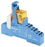
Illustrative purposes only

48P582300060SPA
Power Relay, DPDT, 230 VAC, 8 A, 48 Series, DIN Rail, AC
⚠️ Reference pricing provided. In case of supply shortages, we will connect you with our trusted procurement partners to ensure your project's continuity.
- Manufacturer: FINDER
- Product type: Power Relays
- Coil Type: AC
- Coil Voltage: 230VAC
- Product Range: 48 Series
- Relay Mounting: DIN Rail
- Contact Current: 8A
- Relay Terminals: Quick Connect
- Contact Material: Silver Nickel
- Contact Voltage VAC: 250V
- Contact Voltage VDC: 30V
- Approvals & Standards: CE, CSA, UL
- Contact Configuration: DPDT
| Delivery and price | |
|---|---|
| Units per pack | 50 |
| Price | 17.31 € |
| Current stock | 10+ |
| Lead time | 30 days |
Datasheet

**48 SERIES**

**B**

> **2 CO forcibly guided contacts relay interface 48.12 modules,15.8 mm wide**

## **Type 48.12**

- 2 CO 8 A

- Screw terminals

- Relay with forcibly guided contacts according to EN 50205 Type B

- 35 mm rail (EN 60715) mounting

- Cadmium-free contact material

48.12

## Screw terminal

- 2 CO 8 A

- Forcibly guided contacts relay

• Screw terminals

|**2 CO forcibly guided contacts relay interface**<br>**modules,15.8 mm wide**<br>**Type 48.12**<br>- 2 CO 8 A<br>- Screw terminals<br>• Relay with forcibly guided contacts accordingRelay with forcibly guided contacts according<br>to EN 50205 Type B<br>• 35 mm rail (EN 60715) mounting35 mm rail (EN 60715) mounting<br>• Cadmium-free contact materialCadmium-free contact material<br>48.12<br>Screw terminal<br>According to EN 50205 only 1 NO and 1 NC<br>(11-14 and 21-22 or 11-12 and 21-24) shall be<br>used as forcibly guided contacts.<br>For outline drawing see page 9<br>**Contact specification**<br>Contact configuration|**48.12**<br>• 2 CO 8 A2 CO 8 A<br>• Forcibly guided contacts relayForcibly guided contacts relay<br>• Screw terminalsScrew terminals|**48.12**<br>• 2 CO 8 A2 CO 8 A<br>• Forcibly guided contacts relayForcibly guided contacts relay<br>• Screw terminalsScrew terminals|
|---|---|---|
||2 CO (DPDT)<br>i||
|Rated current/Maximum peak current<br>A|8/15<br>~~ee~~||
|Rated voltage/<br>Maximum switchingvoltage<br>V AC|250/400||
|Rated load AC1<br>VA|2000<br>~~ee~~||
|Rated load AC15 (230 V AC)<br>VA|500<br>~~ee~~<br>~~ee~~||
|Single phase motor rating (230 V AC)<br>kW|0.37<br>~~ee~~<br>~~ee~~||
|Breaking capacity DC1: 30/110/220 V<br>A|8/0.65/0.2<br>~~ee~~||
|Minimum switching load<br>mW (V/mA)|500 (10/10)<br>~~ee~~||
|Standard contact material<br>**Coil specification**<br>Nominal voltage (UN)<br>V AC (50/60 Hz)<br>V DC|AgNi<br>—||
||12 - 24||
|Rated power AC/DC<br>VA (50 Hz)/W|—/0.7<br>~~ee~~||
|Operating range<br>AC<br>DC|—<br>~~ee~~||
||(0.75…1.2)UN<br>~~ee~~||
|Holding voltage<br>AC/DC|—/0.4 UN<br>~~ee~~||
|Must drop-out voltage<br>AC/DC<br>**Technical data**<br>Mechanical life AC/DC<br>cycles|—/0.1 UN<br>—/10 · 106||
|Electrical life at rated load AC1<br>cycles|100 · 103<br>~~ee~~||
|Operate/release time<br>ms|10/4<br>~~ee~~||
|Insulation between coil<br>and contacts(1.2/50µs)<br>kV|6(8 mm)||
|Dielectric strength<br>between open contacts<br>V AC|1500||
|Ambient temperature range<br>°C|–40…+70<br>~~ee~~||
|Protection category|IP 20||
|**Approvals relay**(according to type)|CEHL|HL<br>©AWs|


**1**

**48 SERIES**

## **1 CO relay interface modules,**

**==> picture [26 x 8] intentionally omitted <==**

**----- Start of picture text -----**<br>
48.P3<br>**----- End of picture text -----**<br>


**==> picture [25 x 7] intentionally omitted <==**

**----- Start of picture text -----**<br>
48.31<br>**----- End of picture text -----**<br>


## **15.8 mm wide**

## **Ideal interface for PLC and electronic systems**

## **Type 48.P3**

- 1 CO 10 A

- Push-in terminals

## **Type 48.31**

**B**

- 1 CO 10 A

- Screw terminals

- AC coils or DC sensitive coils

- Supply status indication and EMC coil suppression module as standard

- 1 CO 10 A

- Push-in terminals

   - 1 CO 10 A

   - Screw terminals

- Identification label

- UL Listing (certain relay/socket combinations)

- 35 mm rail (EN 60715) mounting

- Cadmium-free contact material

48.P3 48.31 Push-in terminal Screw terminal

|For outline drawing see page 9|||||||
|---|---|---|---|---|---|---|
|**Contact specification**<br>Contact configuration||1 CO (SPDT)||||1 CO (SPDT)|
|Rated current/Maximum peak current<br>A||10/20||||10/20|
|Rated voltage/<br>Maximum switchingvoltage|V AC|250/400||||250/400|
|Rated load AC1|VA|2500||||2500|
|Rated load AC15 (230 V AC)|VA|500||||500|
|Single phase motor rating (230 V AC)|Single phase motor rating (230 V AC)<br>kW|0.37||||0.37|
|Breaking capacity DC1: 30/110/220 V<br>A||10/0.3/0.12||||10/0.3/0.12|
|Minimum switching load|mW (V/mA)|300 (5/5)||||300 (5/5)|
|Standard contact material<br>**Coil specification**<br>Nominal voltage (UN)|V AC (50/60 Hz)|AgNi<br>12 - 24 - 110 - 120 - 230||||AgNi<br>12 - 24 - 110 - 120 - 230|
||V DC|12 - 24 - 125||||12 - 24 - 125|
|Rated power AC/sens. DC|VA (50 Hz)/W|1.2/0.5||||1.2/0.5|
|Operating range|AC|(0.8…1.1)UN||||(0.8…1.1)UN|
||sens. DC|(0.73…1.5)UN||||(0.73…1.5)UN|
|Holding voltage|AC/DC|0.8 UN/ 0.4 UN||||0.8 UN/ 0.4 UN|
|Must drop-out voltage<br>**Technical data**|AC/DC|0.2 UN/ 0.1 UN||||0.2 UN/ 0.1 UN|
|Mechanical life|cycles|10 · 106||||10 · 106|
|Electrical life at rated load AC1|cycles|200 · 103||||200 · 103|
|Operate/release time|ms|7/4 (AC) - 12/12 (DC)||||7/4 (AC) - 12/12 (DC)|
|Insulation between coil|||||||
|and contacts(1.2/50µs)<br>Dielectric strength<br>between open contacts<br>Ambient temperature range<br>Protection category|kV<br>V AC<br>°C|6(8 mm)<br>1000<br>–40…+70<br>IP 20<br>~~ce@HH&®@~~|~~®@~~|~~B~~|~~RINA~~|6(8 mm)<br>1000<br>–40…+70<br>IP 20<br>~~RINA©Wis&~~|
|**Approvals relay**(according to type)|(according to type)|~~ce@HH&®@~~|~~®@~~|~~B~~|~~RINA~~|~~RINA©Wis&~~|


**2**

**48 SERIES**

**B**

**2 CO relay interface modules, 15.8 mm wide**

**==> picture [26 x 8] intentionally omitted <==**

**----- Start of picture text -----**<br>
48.P5<br>**----- End of picture text -----**<br>


**==> picture [26 x 7] intentionally omitted <==**

**----- Start of picture text -----**<br>
48.52<br>**----- End of picture text -----**<br>


**Ideal interface for PLC and electronic systems**

**Type 48.P5**

- 2 CO 8 A

- Push-in terminals

**Type 48.52**

- 2 CO 8 A

- Screw terminals

- AC coils or DC sensitive coils

- Supply status indication and EMC coil suppression module as standard

**==> picture [35 x 7] intentionally omitted <==**

**----- Start of picture text -----**<br>
• 2 CO 8 A<br>**----- End of picture text -----**<br>


- Push-in terminals

**==> picture [34 x 7] intentionally omitted <==**

**----- Start of picture text -----**<br>
• 2 CO 8 A<br>**----- End of picture text -----**<br>


   - Screw terminals

- Identification label

- UL Listing (certain relay/socket combinations)

- 35 mm rail (EN 60715) mounting

- Cadmium-free contact material

48.P5 48.52 Push-in terminal Screw terminal

||For outline drawing see page 9|||||||
|---|---|---|---|---|---|---|---|
||**Contact specification**<br>Contact configuration||2 CO (DPDT)||||2 CO (DPDT)|
||Rated current/Maximum peak current<br>A||8/15||||8/15|
||Rated voltage/<br>Maximum switchingvoltage|V AC|250/250||||250/250|
||Rated load AC1|VA|2000||||2000|
||Rated load AC15 (230 V AC)|VA|400||||400|
||Single phase motor rating (230 V AC)|Single phase motor rating (230 V AC)<br>kW|0.3||||0.3|
||Breaking capacity DC1: 30/110/220 V<br>A||8/0.3/0.12||||8/0.3/0.12|
||Minimum switching load|mW (V/mA)|300 (5/5)||||300 (5/5)|
||Standard contact material<br>**Coil specification**<br>Nominal voltage (UN)|V AC (50/60 Hz)|AgNi<br>12 - 24 - 110 - 120 - 230||||AgNi<br>12 - 24 - 110 - 120 - 230|
|||V DC|12 - 24 - 125||||12 - 24 - 125|
||Rated power AC/sens. DC|VA (50 Hz)/W|1.2/0.5||||1.2/0.5|
||Operating range|AC|(0.8…1.1)UN||||(0.8…1.1)UN|
|||sens. DC|(0.73…1.5)UN||||(0.73…1.5)UN|
||Holding voltage|AC/DC|0.8 UN/ 0.4 UN||||0.8 UN/ 0.4 UN|
||Must drop-out voltage<br>**Technical data**|AC/DC|0.2 UN/ 0.1 UN||||0.2 UN/ 0.1 UN|
||Mechanical life|cycles|10 · 106||||10 · 106|
||Electrical life at rated load AC1|cycles|100 · 103||||100 · 103|
||Operate/release time|ms|7/4 (AC) - 12/12 (DC)||||7/4 (AC) - 12/12 (DC)|
||Insulation between coil|||||||
||and contacts(1.2/50µs)|kV|6(8 mm)||||6(8 mm)|
|X-2016, www.findernet.com|Dielectric strength<br>between open contacts<br>Ambient temperature range<br>Protection category<br>**Approvals relay**(according to type)|V AC<br>°C<br>(according to type)|1000<br>–40…+70<br>IP 20<br>~~ceGHil©@~~|~~@~~|~~B~~|~~RNA~~|1000<br>–40…+70<br>IP 20<br>~~RNA©Mis@~~|


**3**

**48 SERIES**

## **1 CO relay interface modules,**

**==> picture [26 x 8] intentionally omitted <==**

**----- Start of picture text -----**<br>
48.P6<br>**----- End of picture text -----**<br>


**==> picture [25 x 7] intentionally omitted <==**

**----- Start of picture text -----**<br>
48.61<br>**----- End of picture text -----**<br>


## **15.8 mm wide**

## **Ideal interface for PLC and electronic systems**

## **Type 48.P6**

- 1 CO 16 A

- Push-in terminals

## **Type 48.61**

**B**

- 1 CO 16 A

- Screw terminals

- AC coils or DC sensitive coils

- Supply status indication and EMC coil suppression module as standard

- 1 CO 16 A

- Push-in terminals

   - 1 CO 16 A

   - Screw terminals

- Identification label

- UL Listing (certain relay/socket combinations)

- 35 mm rail (EN 60715) mounting

- Cadmium-free contact material available

48.P6 48.61 Push-in terminal Screw terminal

- For currents > 10 A, contact terminals must be connected in parallel (21 with 11, 24 with 14, 22 with 12).

- For currents > 10 A, contact terminals must be connected in parallel (21 with 11, 24 with 14, 22 with 12).

|||must be connected in parallel|must be connected in parallel|must be connected in parallel|must be connected in parallel|must be connected in parallel|must be connected in parallel|
|---|---|---|---|---|---|---|---|
|For outline drawing see page 9||(21 with 11, 24 with 14, 22 with 12).||||(21 with 11, 24 with 14, 22 with 12).||
|**Contact specification**<br>Contact configuration|||1 CO (SPDT)|||1 CO (SPDT)||
|Rated current/Maximum peak current<br>A||||16*/30||16*/30||
|Rated voltage/<br>Maximum switchingvoltage|V AC|||250/400||250/400||
|Rated load AC1|VA||||4000|4000||
|Rated load AC15 (230 V AC)|VA||||750||750|
|Single phase motor rating (230 V AC)<br>kW|||||0.55||0.55|
|Breaking capacity DC1: 30/110/220 V<br>A|||16/0.3/0.12|||16/0.3/0.12||
|Minimum switching load|mW (V/mA)|||500 (10/5)||500 (10/5)||
|Standard contact material<br>**Coil specification**<br>Nominal voltage (UN)|V AC (50/60 Hz)|12 - 24 - 110 - 120 - 230|AgCdO<br>12 - 24 - 110 - 120 - 230|||AgCdO<br>12 - 24 - 110 - 120 - 230||
||V DC||12 - 24 - 125|||12 - 24 - 125|12 - 24 - 125|
|Rated power AC/sens. DC|VA (50 Hz)/W|||1.2/0.5||1.2/0.5||
|Operating range|AC||(0.8…1.1)UN|||(0.8…1.1)UN||
||sens. DC||(0.8…1.5)UN|||(0.8…1.5)UN||
|Holding voltage|AC/DC||0.8 UN/ 0.4 UN|||0.8 UN/ 0.4 UN||
|Must drop-out voltage<br>**Technical data**|AC/DC||0.2 UN/ 0.1 UN|||0.2 UN/ 0.1 UN||
|Mechanical life|cycles|||10 · 106||10 · 106||
|Electrical life at rated load AC1|cycles|||100 · 103||100 · 103||
|Operate/release time|ms|7/4 (AC) - 12/12 (DC)||||7/4 (AC) - 12/12 (DC)||
|Insulation between coil||||||||
|and contacts(1.2/50µs)<br>Dielectric strength<br>between open contacts<br>Ambient temperature range<br>Protection category|kV<br>V AC<br>°C|~~CEGHIEGO~~|~~CEGHIEGO~~|6(8 mm)<br>1000<br>–40…+70<br>IP 20<br>~~B RINAOAsO~~||6(8 mm)<br>1000<br>–40…+70<br>IP 20<br>~~CESHES ®@ RINA Wis~~||
|**Approvals relay**(according to type)||~~CEGHIEGO~~|~~CEGHIEGO~~|~~B RINAOAsO~~|~~RINAOAsO~~|~~CESHES ®@~~|~~®@ RINA Wis~~|


**4**

**48 SERIES**

**B**

**2 CO relay interface modules, 15.8 mm wide**

**==> picture [26 x 8] intentionally omitted <==**

**----- Start of picture text -----**<br>
48.P8<br>**----- End of picture text -----**<br>


**==> picture [26 x 7] intentionally omitted <==**

**----- Start of picture text -----**<br>
48.62<br>**----- End of picture text -----**<br>


**Ideal interface for PLC and electronic systems**

## **Type 48.P8**

- 2 CO 10 A

- Push-in terminals

**Type 48.62**

- 2 CO 10 A

- Screw terminals

- DC sensitive coils

- Supply status indication and EMC coil suppression module as standard

- 2 CO 10 A

- Push-in terminals

**==> picture [39 x 7] intentionally omitted <==**

**----- Start of picture text -----**<br>
• 2 CO 10 A<br>**----- End of picture text -----**<br>


   - Screw terminals

- Identification label

- UL Listing (certain relay/socket combinations)

- 35 mm rail (EN 60715) mounting

- Cadmium-free contact material

48.P8 48.62

Push-in terminal Screw terminal

||For outline drawing see page 9||||
|---|---|---|---|---|
||**Contact specification**<br>Contact configuration||2 CO (DPDT)<br>2 CO (DPDT)||
||Rated current/Maximum peak current<br>A||10/20<br>10/20<br>~~es~~||
||Rated voltage/<br>Maximum switchingvoltage|V AC|250/400<br>250/400||
||Rated load AC1<br>Rated load AC15 (230 V AC)|VA<br>VA|2500<br>2500<br>500<br>500<br>~~es~~<br>~~es~~||
||Single phase motor rating (230 V AC)<br>kW||0.37<br>0.37<br>~~es~~||
||Breaking capacity DC1: 30/110/220 V<br>A||10/0.3/0.12<br>10/0.3/0.12<br>~~es~~||
||Minimum switching load|mW (V/mA)|300 (5/5)<br>300 (5/5)<br>~~es~~||
||Standard contact material<br>**Coil specification**<br>Nominal voltage (UN)|V AC (50/60 Hz)|AgNi<br>AgNi<br>—<br>—||
|||V DC|12 - 24 - 125<br>12 - 24 - 125<br>~~es~~||
||Rated power AC/sens. DC|VA (50 Hz)/W|—/0.5<br>—/0.5<br>~~es~~||
||Operating range|AC|—<br>—<br>~~es~~||
|||sens. DC|(0.8…1.5)UN<br>(0.8…1.5)UN<br>~~es~~||
||Holding voltage|AC/DC|—/0.4 UN<br>—/0.4 UN<br>~~es~~||
||Must drop-out voltage<br>**Technical data**|AC/DC|—/0.1 UN<br>—/0.1 UN||
||Mechanical life|cycles|20 · 106<br>20 · 106||
||Electrical life at rated load AC1|cycles|100 · 103<br>100 · 103<br>~~es~~||
||Operate/release time|ms|12/12 (DC)<br>12/12 (DC)<br>~~es~~||
||Insulation between coil||||
||and contacts(1.2/50µs)|kV|6(8 mm)<br>6(8 mm)||
|X-2016, www.findernet.com|Dielectric strength<br>between open contacts<br>V AC<br>Ambient temperature range<br>°C<br>Protection category<br>**Approvals relay**(according to type)||1000<br>1000<br>–40…+70<br>–40…+70<br>IP 20<br>IP 20<br>~~es~~<br>~~ee~~<br>CEGHIE®<br>BRINAOMisGE CESELS ® RINAWiis||


**5**

**48 SERIES**

## **Ordering information**

Example:  48 series, 35 mm rail (EN 60715) mount, Push-in terminal relay interface module, 2 CO 8 A contacts, 24 V sensitive DC coil, green LED + diode, 99.02 coil indication.

**A B C D 4 8 . P 5 . 7 . 0 2 4 . 0 0 5 0**

**B Series**

## **Type**

Screw terminal

- 1 =  35 mm rail (EN 60715) mount, forcibly guided contacts relay

- 3 =  35 mm rail (EN 60715) mount

- 5 =  35 mm rail (EN 60715) mount

- 6 =  35 mm rail (EN 60715) mount

- Push-in terminal

- P =  35 mm rail (EN 60715) mount

## **A: Contact material**

- 0 =  Standard AgNi for

48.P3/P5/P8/31/52/62 AgCdO, Standard for 48.P6/61

- 1=  AgNi, for 48.12

- 4 =  AgSnO2, for 48.P6/P8/ 61/62 only

- 5 =  AgNi + Au, for 48.P3/P5/31/52 only

## **D: Special versions**

- 0 =  Standard

- 2 =  Standard (for 48.12 only)

## **C: Options**

- 0 =  Standard (for 48.12 only)

- 5 =  Standard for DC: green LED + diode (polarity +A1)

- 6 =  Standard for AC: green LED + Varistor

## **B: Contact circuit**

## **Type**

- 0 =  CO (nPDT)

Screw terminal 1 = for  48.31, 10 A 48.61, 16 A

- 2 = for  48.12 (DC only), 48.52, 8 A 48.62 (DC only), 10 A

Push-in terminal

- 3 = for 48.P3, 10 A

- 5 = for 48.P5, 8 A

- 6 = for 48.P6, 16 A

- 8 = for 48.P8 (DC only), 10 A

## **Coil version**

7 =  Sensitive DC

- 8 =  AC (50/60 Hz)

- 9 = DC (for 48.12 only)

**Coil voltage** See coil specifications

**Selecting features and options: only combinations in the same row are possible.** Preferred selections for best availability are shown in **bold.**

||**Type**|**Coil version**|**A**|**B**|**C**|**D**|
|---|---|---|---|---|---|---|
||48.12|DC|**1**|**0**|**0**|**2**|
||48.P3/P5/31/52<br>48.P3/P5/31/52|AC<br>Sensitive DC|**0**- 5<br>**0**- 5|0<br>0|**6**<br>**5**|0<br>0|
||48.P6/61|AC|**0**- 4|0|**6**|0|
||48.P6/61|Sensitive DC|**0**- 4|0|**5**|0|
||48.P8/62|Sensitive DC|**0**- 4|0|**5**|0|


## **Technical data**

|**Insulation**|||**48.12/31/61/P3/P6 **|**48.52/P5**|**48.12/31/61/62/P3/P6/P8**|**48.12/31/61/62/P3/P6/P8**|
|---|---|---|---|---|---|---|
|Insulation according to EN 61810-1|insulation rated voltage|V|250|250|400||
||rated impulse withstand voltage|<br>kV|4|4|4||
||pollution degree||3|2|2||
||overvoltage category||III|III|III||
|Insulation between coil and contacts (1.2/50µs)||kV|6 (8 mm)||||
|Dielectric strength between open contacts||V AC|1000; 1500 (48.12)||||
|Dielectric strength between adjacent contacts||V AC|2000 (48.P5/52); 2500 (48.12/P6)||||
|**Conducted disturbance immunity**|||||||
|Burst (5…50)ns, 5 kHz, on A1 - A2|||EN 61000-4-4||level 4 (4 kV)||
|Surge (1.2/50 µs) on A1 - A2 (differential mode)|||EN 61000-4-5||level 3 (2 kV)||
|**Other data**|||||||
|Bounce time: NO/NC||ms|2/5; 2/10 (48.12)||||
|Vibration resistance (10…200)Hz: NO/NC||g|20/5 (for 1pole)||15/3; 20/6 (48.12) for 2pole||
|Power lost to the environment|without contact current|W|0.7||||
||with rated current|W|1.2 (48.12/31/P3)|1.3 (48.52/P5)|1.2 (48.61/62/P6/P8)||
|Wire striplength<br>||mm|8||||
|Screw torque (only for 48.12/31/52/61/81)||Nm|0.5||||
|Max. wire size||mm2|**Screw terminal**||**Push-in terminal**||
||||solid cable|stranded cable|solid cable|stranded cable|
||||1 x 6 / 2 x 2.5|1 x 4 / 2 x 2.5|2 x (0.5…1.5)|2 x (0.5…1.5)|
|||AWG|1 x 10 / 2 x 14|1 x 12 / 2 x 14|2 x (21…18)|2 x (21…18)|
||||||||


**6**

**48 SERIES**

**B**

## **Contact specification**

**F 48 - Electrical life (AC) v contact current** Types 48.P3/P6/31/61

**==> picture [252 x 303] intentionally omitted <==**

**----- Start of picture text -----**<br>
Resistive load - cos ϕ = 1<br>Inductive load- cos ϕ  = 0.4<br>limit for 48.31<br>F 48 - Electrical life (AC) v contact current<br>Types 48.P5/52<br>Resistive load - cos ϕ = 1<br>Inductive load- cos ϕ = 0.4<br>Cycles<br>Cycles<br>**----- End of picture text -----**<br>


**==> picture [252 x 325] intentionally omitted <==**

**----- Start of picture text -----**<br>
H 48 - Maximum DC1 breaking capacity<br>Types 48.P3/P5/P6/31/52/61<br>48.P6/61 current limit<br>48.P3/31 current limit<br>48.P5/52 current limit<br>2 contacts in series<br>single contact<br>DC voltage (V)<br>H 48 - Maximum DC1 breaking capacity<br>Type 48.12<br>DC voltage (V)<br>DC breaking current (A)<br>DC breaking current (A)<br>**----- End of picture text -----**<br>


**F 48 - Electrical life (AC) v contact current** Types 48.P8/62

**==> picture [213 x 108] intentionally omitted <==**

**----- Start of picture text -----**<br>
Resistive load - cos ϕ  = 1<br>Inductive load- cos ϕ  = 0.4<br>Cycles<br>**----- End of picture text -----**<br>


## **F 48 - Electrical life (AC) v contact current**

Type 48.12

**==> picture [214 x 108] intentionally omitted <==**

**----- Start of picture text -----**<br>
Resistive load - cos ϕ  = 1<br>Inductive load- cos ϕ  = 0.4<br>Cycles<br>**----- End of picture text -----**<br>


**H 48 - Maximum DC1 breaking capacity** Types 48.P8/62

**==> picture [213 x 121] intentionally omitted <==**

**----- Start of picture text -----**<br>
2 contacts in series<br>single contact<br>DC voltage (V)<br>DC breaking current (A)<br>**----- End of picture text -----**<br>


- When switching a resistive load (DC1) having voltage and current values under the curve, an electrical life of ≥ 100 · 10[3] can be expected.

- In the case of DC13 loads, the connection of a diode in parallel with the load will permit a similar electrical life as for a DC1 load. Note: the release time for the load will be increased.

**7**

**48 SERIES**

## **Coil specifications**

**B**

## **DC coil data (0.5 W sensitive)**

|Nominal<br>voltage<br>UN|Coil<br>code|Operating range<br>Umin*<br>Umax|Operating range<br>Umin*<br>Umax|Rated coil<br>consumption<br>Iat UN|
|---|---|---|---|---|
|V||V|V|mA|
|12|**7**.012|8.8|18|41|
|24|**7**.024|17.5|36|22.2|
|125|**7**.125|91|188|4|


- Umin = 0.8 UN for 48.61, 48.62, 48.P6, 48.P8

## **AC coil data**

|**AC coil data**|||||
|---|---|---|---|---|
|Nominal<br>voltage<br>UN|Coil<br>code|Operating range<br>Umin<br>Umax||Rated coil<br>consumption<br>Iat UN(50 Hz)|
|V||V|V|mA|
|12|**8**.012|9.6|13.2|90.5|
|24|**8**.024|19.2|26.4|46|
|110|**8**.110|88|121|10.1|
|120|**8**.120|96|132|11.8|
|230|**8**.230|184|253|7.0|


## **DC coil data,** 2 pole relay - Type 48.12

|Nominal<br>voltage<br>UN|Coil<br>code|Operating range<br>Umin<br>Umax|Operating range<br>Umin<br>Umax|Resistance<br>R|Rated coil<br>consumption<br>Iat UN|
|---|---|---|---|---|---|
|V||V|V|Ω|mA|
|12|**9**.012|9|14.4|205|58.5|
|24|**9**.024|18|28.8|820|29.3|


## **R 48 - DC coil operating range v ambient temperature**

**==> picture [191 x 104] intentionally omitted <==**

**----- Start of picture text -----**<br>
48.P3/P5/31/52<br>48.P6/P8/61/62 1<br>48.P6/P8/61/62<br>2<br>48.P3/P5/31/52<br>**----- End of picture text -----**<br>


**==> picture [104 x 9] intentionally omitted <==**

**----- Start of picture text -----**<br>
1 -   Max. permitted coil voltage.<br>**----- End of picture text -----**<br>


**2 -** Min. pick-up voltage with coil at ambient temperature.

## **R 48 - AC coil operating range v ambient temperature**

**==> picture [190 x 103] intentionally omitted <==**

**----- Start of picture text -----**<br>
1<br>2<br>**----- End of picture text -----**<br>


**==> picture [104 x 9] intentionally omitted <==**

**----- Start of picture text -----**<br>
1 -   Max. permitted coil voltage.<br>**----- End of picture text -----**<br>


**==> picture [192 x 8] intentionally omitted <==**

**----- Start of picture text -----**<br>
2 -   Min. pick-up voltage with coil at ambient temperature.<br>**----- End of picture text -----**<br>


## **R 48 - DC coil operating range v ambient temperature**

## **Type 48.12**

**==> picture [215 x 128] intentionally omitted <==**

**==> picture [104 x 8] intentionally omitted <==**

**----- Start of picture text -----**<br>
1 -   Max. permitted coil voltage.<br>**----- End of picture text -----**<br>


**2 -** Min. pick-up voltage with coil at ambient temperature.

**8**

**48 SERIES**

## **Combinations**

|**Code**<br>**Type of socket**<br>**Type of relay**<br>**Module**<br>**Retaining clip**<br>48.12<br>95.05.0<br>50.12<br>—<br>095.71<br>48.31<br>95.03<br>40.31<br>99.02<br>095.01<br>~~4~~<br>~~2~~<br>95.05<br>40.52<br>99.02<br>095.01<br>48.61<br>95.05<br>40.61<br>99.02<br>095.01<br>48.62<br>95.05<br>44.62<br>99.02<br>095.01<br>48.P3<br>95.P3<br>40.31<br>99.02<br>095.91.3<br>48.P5<br>95.P5<br>40.52<br>99.02<br>095.91.3<br>48.P6<br>95.P5<br>40.61<br>99.02<br>095.91.3<br>48.P8<br>95.P5<br>44.62<br>99.02<br>095.91.3<br>**awing**<br>~~es~~<br>~~es~~<br>~~ee~~<br>~~ee~~<br>~~ee~~<br>~~ee~~<br>~~a~~<br>~~ee~~<br>~~es~~<br>~~ee~~|**Code**<br>**Type of socket**<br>**Type of relay**<br>**Module**<br>**Retaining clip**<br>48.12<br>95.05.0<br>50.12<br>—<br>095.71<br>48.31<br>95.03<br>40.31<br>99.02<br>095.01<br>~~4~~<br>~~2~~<br>95.05<br>40.52<br>99.02<br>095.01<br>48.61<br>95.05<br>40.61<br>99.02<br>095.01<br>48.62<br>95.05<br>44.62<br>99.02<br>095.01<br>48.P3<br>95.P3<br>40.31<br>99.02<br>095.91.3<br>48.P5<br>95.P5<br>40.52<br>99.02<br>095.91.3<br>48.P6<br>95.P5<br>40.61<br>99.02<br>095.91.3<br>48.P8<br>95.P5<br>44.62<br>99.02<br>095.91.3<br>**awing**<br>~~es~~<br>~~es~~<br>~~ee~~<br>~~ee~~<br>~~ee~~<br>~~ee~~<br>~~a~~<br>~~ee~~<br>~~es~~<br>~~ee~~|**Code**<br>**Type of socket**<br>**Type of relay**<br>**Module**<br>**Retaining clip**<br>48.12<br>95.05.0<br>50.12<br>—<br>095.71<br>48.31<br>95.03<br>40.31<br>99.02<br>095.01<br>~~4~~<br>~~2~~<br>95.05<br>40.52<br>99.02<br>095.01<br>48.61<br>95.05<br>40.61<br>99.02<br>095.01<br>48.62<br>95.05<br>44.62<br>99.02<br>095.01<br>48.P3<br>95.P3<br>40.31<br>99.02<br>095.91.3<br>48.P5<br>95.P5<br>40.52<br>99.02<br>095.91.3<br>48.P6<br>95.P5<br>40.61<br>99.02<br>095.91.3<br>48.P8<br>95.P5<br>44.62<br>99.02<br>095.91.3<br>**awing**<br>~~es~~<br>~~es~~<br>~~ee~~<br>~~ee~~<br>~~ee~~<br>~~ee~~<br>~~a~~<br>~~ee~~<br>~~es~~<br>~~ee~~|**Code**<br>**Type of socket**<br>**Type of relay**<br>**Module**<br>**Retaining clip**<br>48.12<br>95.05.0<br>50.12<br>—<br>095.71<br>48.31<br>95.03<br>40.31<br>99.02<br>095.01<br>~~4~~<br>~~2~~<br>95.05<br>40.52<br>99.02<br>095.01<br>48.61<br>95.05<br>40.61<br>99.02<br>095.01<br>48.62<br>95.05<br>44.62<br>99.02<br>095.01<br>48.P3<br>95.P3<br>40.31<br>99.02<br>095.91.3<br>48.P5<br>95.P5<br>40.52<br>99.02<br>095.91.3<br>48.P6<br>95.P5<br>40.61<br>99.02<br>095.91.3<br>48.P8<br>95.P5<br>44.62<br>99.02<br>095.91.3<br>**awing**<br>~~es~~<br>~~es~~<br>~~ee~~<br>~~ee~~<br>~~ee~~<br>~~ee~~<br>~~a~~<br>~~ee~~<br>~~es~~<br>~~ee~~|**Code**<br>**Type of socket**<br>**Type of relay**<br>**Module**<br>**Retaining clip**<br>48.12<br>95.05.0<br>50.12<br>—<br>095.71<br>48.31<br>95.03<br>40.31<br>99.02<br>095.01<br>~~4~~<br>~~2~~<br>95.05<br>40.52<br>99.02<br>095.01<br>48.61<br>95.05<br>40.61<br>99.02<br>095.01<br>48.62<br>95.05<br>44.62<br>99.02<br>095.01<br>48.P3<br>95.P3<br>40.31<br>99.02<br>095.91.3<br>48.P5<br>95.P5<br>40.52<br>99.02<br>095.91.3<br>48.P6<br>95.P5<br>40.61<br>99.02<br>095.91.3<br>48.P8<br>95.P5<br>44.62<br>99.02<br>095.91.3<br>**awing**<br>~~es~~<br>~~es~~<br>~~ee~~<br>~~ee~~<br>~~ee~~<br>~~ee~~<br>~~a~~<br>~~ee~~<br>~~es~~<br>~~ee~~|**Type of socket**<br>**Type of relay**<br>95.05.0<br>50.12|**Type of relay**<br>50.12|**Module**<br>—|**Retaining clip**<br>095.71|
|---|---|---|---|---|---|---|---|---|
||48.31<br>95.03<br>~~es~~||||95.03<br>40.31<br>~~es~~|40.31<br>~~es~~|99.02<br>~~es~~|095.01|
||48.31||||||||
||~~4~~<br>~~2~~|||95.05<br>~~es~~<br>~~es~~|95.05<br>40.52<br>~~es~~<br>~~es~~|40.52<br>~~es~~<br>~~es~~<br>~~ee~~|99.02<br>~~es~~<br>~~es~~|095.01|
||~~4~~<br>~~2~~||||||||
||48.61|||95.05<br>~~es~~<br>~~ee~~<br>~~a~~|95.05<br>40.61<br>~~es~~<br>~~ee~~<br>~~a~~|40.61<br>~~es~~<br>~~ee~~<br>~~ee~~<br>~~ee~~|99.02<br>~~es~~<br>~~ee~~|095.01|
||48.62|||95.05<br>~~ee~~<br>~~ee~~<br>~~a~~|95.05<br>44.62<br>~~ee~~<br>~~ee~~<br>~~a~~|44.62<br>~~ee~~<br>~~ee~~<br>~~ee~~<br>~~ee~~|99.02<br>~~ee~~<br>~~ee~~|095.01|
||48.P3|||95.P3<br>~~ee~~<br>~~a~~<br>~~ee~~|95.P3<br>40.31<br>~~ee~~<br>~~a~~<br>~~ee~~|40.31<br>~~ee~~<br>~~ee~~|99.02<br>~~ee~~|095.91.3|
||||||||||
||48.P5|||95.P5<br>~~a~~<br>~~ee~~<br>~~es~~|95.P5<br>40.52<br>~~a~~<br>~~ee~~<br>~~es~~|40.52<br>~~ee~~|99.02|095.91.3|
||48.P6|||95.P5<br>~~ee~~<br>~~es~~|95.P5<br>40.61<br>~~ee~~<br>~~es~~|40.61|99.02|095.91.3|
||48.P8|||95.P5<br>~~es~~<br>~~ee~~|95.P5<br>44.62<br>~~es~~<br>~~ee~~|44.62<br>~~ee~~|99.02<br>~~ee~~|095.91.3|
||||||||||
|**awing**|||||||||


**B**

## **O line awing**

**==> picture [395 x 179] intentionally omitted <==**

**----- Start of picture text -----**<br>
64.5<br>15.8 25.9 17.5 17.5<br>_<br>|<br>i, Lue L 2 eS = 32 7<br>48.31  48.52 / 48.61 / 48.62 48.12<br>Screw terminal Screw terminal<br>21.6<br>78.6 35.4<br>25.5<br>**----- End of picture text -----**<br>


**==> picture [245 x 15] intentionally omitted <==**

**----- Start of picture text -----**<br>
48.P3  48.P5  48.P6  48.P8<br>Push-in terminal<br>**----- End of picture text -----**<br>


**9**

**48 SERIES**

## **Accessories**

**B**

**==> picture [508 x 496] intentionally omitted <==**

**----- Start of picture text -----**<br>
8-way jumper link  for type 48.P3/P5/P6/P8 097.58<br>Rated values 10 A - 250 V<br>097.58 c=)© PRA| 15.8LLLLLAAAAR LL y)3s<br>tren 56<br>2-way jumper link  for type 48.P3/P5/P6/P8 097.52<br>Rated values 10 A - 250 V<br>097.52 aS PTT | |<br>( a a . 1<br>2-way jumper link  for type 48.P3/P5/P6/P8 097.42<br>Rated values 10 A - 250 V<br>2<br>097.42<br>©<br>oO<br>— [([s)]<br>Marker tag holder  for type 48.P3/P5/P6/P8 and 48.12/31/52/61/62 097.00<br>5 . 6 44<br>097.00<br>ey<br>8-way jumper link  for screw terminal version 095.18 (blue) 095.18.0 (black)<br>Rated values 10 A - 250 V<br>095.18<br>WS ee<br>if 110.5 5<br>Sheet of marker tags (CEMBRE'S Thermal transfer printers) ,<br>060.48<br>plastic, 48 tags, 6 x 12 mm<br>FLEE:<br>060.48<br>P E A<br>P A T E N T<br>RO N<br>U<br>E E<br>U<br>NA E POR<br>**----- End of picture text -----**<br>


## **Packaging codes**

**How to code and identify retaining clip and packaging options for sockets.**

Example:

**4 8 . P 5 . 7 . 0 2 4 . 0 0 5 0 S P A A** Standard packaging **B** Blister packaging **SP** Plastic retaining clip

**10**
Updated at February 9, 2023
About Novapart
Novapart is a B2B electronic component broker specialising in stock shortages and cost reduction. We source hard-to-find parts and identify compliant alternatives across a catalogue of 410,000+ components from 500+ manufacturers.
Learn more →Stock Shortage Specialist
When a component is unavailable, discontinued or has an unacceptable lead time, we tap into our network of vetted European and Asian distributors to source what you need — without compromising on quality or traceability.
Request a quote →Compliant Alternatives
We identify pin-to-pin, electrically equivalent substitutes that meet the same certifications (RoHS, AEC-Q100, REACH) as your original specification — validated against datasheets, not just part numbers. Often at a lower cost.
BOM Analysis service →