
Image not available
Illustrative purposes only

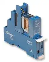
48.61.8.230.0060SPA
General Purpose Relay, 48 Series, Interface, SPDT, 230 VAC, 16 A
⚠️ Reference pricing provided. In case of supply shortages, we will connect you with our trusted procurement partners to ensure your project's continuity.
- Manufacturer: FINDER
- Product type: Power Relays
- Contact Configuration:SPDT; Coil Voltage:230VAC; Contact Current:16A; Product Range:48 Series; Relay Mounting:DIN Rail; Coil Type:AC; Contact Voltage VAC:250VAC; Relay Terminals:Screw; Contact V
- SVHC: No SVHC (25-Jun-2025)
- Coil Type: AC
- Coil Voltage: 230VAC
- Product Range: 48 Series
- Relay Mounting: DIN Rail
- Coil Resistance: -
- Contact Current: 16A
- Relay Terminals: Screw
- Contact Material: Silver Cadmium Oxide
- Contact Voltage VAC: 250V
- Contact Voltage VDC: 30V
- Approvals & Standards: CSA, UL, VDE
- Contact Configuration: SPDT
| Delivery and price | |
|---|---|
| Units per pack | 50 |
| Price | 17.81 € |
| Current stock | 10+ |
| Lead time | 30 days |
Datasheet

**48 Series - Relay interface modules 8 - 10 - 16 A** © ~~fi~~ nder ~~ee~~

**48**

## **Features**

**==> picture [27 x 9] intentionally omitted <==**

**----- Start of picture text -----**<br>
48.31<br>**----- End of picture text -----**<br>


**==> picture [27 x 9] intentionally omitted <==**

**----- Start of picture text -----**<br>
48.52<br>**----- End of picture text -----**<br>


**==> picture [27 x 9] intentionally omitted <==**

**----- Start of picture text -----**<br>
48.61<br>**----- End of picture text -----**<br>


## **1 & 2 Pole relay interface modules, 15.8 mm wide.**

**Ideal interface for PLC and electronic systems**

   - **48.31 - 1 Pole 10 A 48.52 - 2 Pole   8 A 48.61 - 1 Pole 16 A**

- AC coils or DC sensitive coils

- Instant ejection of relay using plastic retaining clip

- Supply status indication and EMC coil suppression module as standard

**==> picture [49 x 10] intentionally omitted <==**

**----- Start of picture text -----**<br>
•<br> 1 pole 10 A<br>**----- End of picture text -----**<br>


- 35 mm rail mounting

- 2 pole 8 A

      - 1 pole 16 A

   - •

   - 35 mm rail mounting 35 mm rail mounting

- Identification label

- UL Listed

- 35 mm rail (EN 50022) mounting

**==> picture [135 x 143] intentionally omitted <==**

**----- Start of picture text -----**<br>
75.3<br>60.9<br>25.9 17.5 17.5<br>RN Pp<br>_<br>15.8 15.8 32<br>._<br>48.31   48.52/61<br>78.6<br>**----- End of picture text -----**<br>


**75.3 11 COM 11 COM 21 11 COM 21 11 COM 21 11 COM 21 11 COM 60.9 14 NO 14 NO 24 14 NO 24 14 NO 24 14 NO 24 14 NO 25.9 17.5 17.5 12 NC 12 NC 22 12 NC 22 12 NC 22 12 NC 22 12 NC A2 A1 A2 A1 A2 A1 A2 A1 A2 A1 A2 A1** RN Pp [ Oo Oi 1 O io Oo CT **AC DC AC DC AC** DC _ **15.8 15.8 32** ~~._~~ 48.31   48.52/61 **Contact specification** Contact configuration 1 CO (SPDT) 2 CO (DPDT) 1 CO (SPDT) Rated current/Maximum peak current A ~~es~~ 10/20 8/15 16/30 Rated voltage/Maximum switching voltage V AC ~~es~~ 250/400 250/250 250/400 Rated load AC1 VA es 2,500 2,000 4,000 Rated load AC15 (230 V AC) VA es 500 400 750 Single phase motor rating (230 V AC) kW es 0.37 0.3 0.55 Breaking capacity DC1: 30/110/220V A es 10/0.3/0.12 8/0.3/0.12 16/0.3/0.12 Minimum switching load mW (V/mA) es 300 (5/5) 300 (5/5) 500 (10/5) Standard contact material AgNi AgNi AgCdO **Coil specification** Nominal voltage (UN) V AC (50/60 Hz) 12 - 24 - 110 - 120 - 230 12 - 24 - 110 - 120 - 230 12 - 24 - 110 - 120 - 230 V DC ~~se~~ 12 - 24 - 125 12 - 24 - 125 12 - 24 - 125 Rated power AC/sens. DC VA (50 Hz)/W ~~es~~ 1.2/0.5 1.2/0.5 1.2/0.5 Operating range AC es (0.8…1.1)UN (0.8…1.1)UN (0.8…1.1)UN sens. DC es (0.73…1.75)UN (0.73…1.75)UN (0.8…1.5)UN Holding voltage AC/DC es 0.8 UN /0.4 UN 0.8 UN /0.4 UN 0.8 UN /0.4 UN Must drop-out voltage AC/DC 0.2 UN /0.1 UN 0.2 UN /0.1 UN 0.2 UN /0.1 UN **Technical data** Mechanical life AC/DC cycles 10 · 10[6] /20 · 10[6] 10 · 10[6] /— 10 · 10[6] /20 · 10[6] Electrical life at rated load AC1 cycles ~~es~~ 200 · 10[3] 100 · 10[3] 100 · 10[3] Operate/release time ms ~~es~~ 7/4 (AC) - 12/12 (DC) 7/4 (AC) - 12/12 (DC) 7/4 (AC) - 12/12 (DC) Insulation between coil and contacts (1.2/50 µs) kV es 6 (8 mm) 6 (8 mm) 6 (8 mm) Dielectric strength between open contacts V AC es 1,000 ee 1,000 1,000 Ambient temperature range °C es –40…+70 –40…+70 –40…+70 Protection category e IP 20 IP 20 s IP 20 **Approvals relay** (according to type)

**125**

## **48 Series - Relay interface modules 8 - 10 - 16 A**

## **Features**

## **48.62**

## **2 Pole relay interface module, 15.8 mm wide.**

## **Ideal interface for PLC and electronic systems**

## **48.62 - 2 Pole 10 A**

- DC sensitive coil

- Instant ejection of relay using plastic retaining clip

- Supply status indication and EMC coil suppression module as standard

- Identification label

   - 2 pole 10 A

   - 35 mm rail mounting

- Cadmium Free contacts

- UL Listed

- 35 mm rail (EN 50022) mounting

**==> picture [274 x 145] intentionally omitted <==**

**----- Start of picture text -----**<br>
75.3<br>60.9 21 11 COM<br>25.9 17.5 17.5 24 14 NO<br>ea, | fF 22 12 NC<br>A2 A1<br>E<br>| DC<br>15.8 32<br>48 48.62<br>78.6<br>— +<br>**----- End of picture text -----**<br>


## —

## **Contact specification**

|Contact configuration||||2 CO (DPDT)|2 CO (DPDT)|
|---|---|---|---|---|---|
|Rated current/Maximum peak current|||A|10/20<br>Pe||
|Rated voltage/Maximum switching voltage V AC||||250/400<br>Pe||
|Rated load AC1|||VA|2,500<br>Pe||
|Rated load AC15 (230 V AC)|||VA|500<br>Pe||
|Single phase motor rating (230 V AC)||Single phase motor rating (230 V AC)|kW|0.37<br>Pe||
|Breaking capacity DC1: 30/110/220V|||A|10/0.3/0.12<br>Po||
|Minimum switching load||mW (V/mA)||300 (5/5)<br>Po||
|Standard contact material|||||AgNi|
|**Coil specification**||||||
|Nominal voltage (UN)|V AC (50/60 Hz)||||—|
||||V DC|12 - 24 - 125<br>Pe||
|Rated power AC/sens. DC||VA (50 Hz)/W||—/0.5<br>Pe||
|Operating range|||AC|—<br>Pe||
|||sens. DC||(0.8…1.5)UN<br>Pe||
|Holding voltage||AC/DC||—/0.4 UN<br>Pe||
|Must drop-out voltage||AC/DC||—/0.1 UN||
|**Technical data**||||||
|Mechanical life AC/DC|||cycles|—/20 · 106||
|Electrical life at rated load AC1|||cycles|100 · 103<br>Pe||
|Operate/release time|||ms|12/12 (DC)<br>Pe||
|Insulation between coil and contacts (1.2/50µs) kV||||6 (8 mm)<br>Pe||
|Dielectric strength between open contacts|||V AC|1,000<br>Pe||
|Ambient temperature range|||°C|–40…+70<br>Pe||
|Protection category||||IP 20<br>Pe||
|**Approvals relay**(according to type)|(according to type)|||||


**126**

**48 Series - Relay interface modules 8 - 10 - 16 A**

## **Ordering information**

Example: 48 series, 35 mm rail (EN 50022) mount relay interface module, 2 CO (DPDT) 8 A contacts, 24 V sensitive DC coil, green LED + diode.

**==> picture [319 x 62] intentionally omitted <==**

**----- Start of picture text -----**<br>
A B C D<br>4 8 . 5 2 . 7 . 0 2 4 . 0 0 5 0<br>A: Contact material D: Special versions<br>0 = Standard<br>**----- End of picture text -----**<br>


**D: Special versions**

**Series**

0 = Standard

**Type** 3 = 35 mm rail mount 5 = 35 mm rail mount 6 = 35 mm rail mount

**B: Contact circuit** 0 = CO (nPDT)

**C: Options** 5 = Standard for DC: green LED + diode (polarity +A1) 6 = Standard for AC: green LED + Varistor

**No. of poles** 1 = 1 pole for 48.31, 10 A 48.61, 16 A 2 = 2 pole for 48.52,  8 A 48.62, 10 A, DC only

**Coil version**

7 = Sensitive DC 8 = AC (50/60 Hz)

**Coil voltage** see coil specifications

## **48**

## **Technical data**

|**Insulation**|||**48.31/61/62 **|**48.52**|**48.31/52/61/62**|**48.31/52/61/62**|
|---|---|---|---|---|---|---|
|Insulation according to EN 61810-1 ed. 2<br>insulation rated voltage<br>V <br>rated impulse withstand voltage<br>kV <br>pollution degree<br>overvoltage category<br>Insulation between coil and contacts (1.2/50µs)<br>kV <br>Dielectric strength between open contacts<br>V AC <br>Dielectric strength between adjacent contacts<br>V AC|insulation rated voltage<br>V||250|250|400||
||rated impulse withstand voltage<br>kV||4|4|4||
||pollution degree||3|2|2||
||overvoltage category||III|III|III||
||||6 (8 mm)||||
||||1,000||||
||||2,000 (48.52); 2,500 (48.62)||||
|**Conducted disturbance immunity**|||||||
|Burst(5...50)ns,5 kHz,on A1 - A2<br>Surge (1.2/50µs) on A1 - A2 (differential mode)|||EN 61000-4-4||level 4(4 kV)||
||||EN 61000-4-5||level 3 (2 kV)||
|**Other data**|||||||
|Bounce time: NO/NC||ms|2/5||||
|Vibration resistance(5…55)Hz, max. ± 1 mm|: NO/NC|g/g|10/4(for 1pole)||15/3(for 2pole)||
|Power lost to the environment|without contact current|W|0.7||||
||with rated current|W|1.2 (48.31)|1.3 (48.52)|1.2 (48.61)|1.2 (48.62)|
|Wire strip length<br>S t||mm <br>N|8<br>05||||
|crew orque<br>Max. wire size|m <br>mm2<br>AWG|m|.<br>solid cable<br>stranded cable||||
|||mm2|1x6 / 2x2.5||1x4 / 2x2.5||
||||1x10 / 2x14||1x12 / 2x14||


**127**

## **48 Series - Relay interface modules 8 - 10 - 16 A**

## **Contact specification**

**F 48 - Electrical life (AC) v contact current** Types 48.31/61

**==> picture [250 x 141] intentionally omitted <==**

**----- Start of picture text -----**<br>
107<br>Resistive load - cos ϕ  = 1<br>Inductive load- cos ϕ  = 0.4<br>106<br>limit for 48.31<br>105<br>0 4 8 12 16<br>(A)<br>Cycles<br>**----- End of picture text -----**<br>


## **F 48 - Electrical life (AC) v contact current**

Type 48.62

**==> picture [250 x 141] intentionally omitted <==**

**----- Start of picture text -----**<br>
107<br>106 Resistive load - cos ϕ  = 1<br>Inductive load - cos ϕ  = 0.4<br>105<br>0 4 8 12 16<br>(A)<br>Cycles<br>**----- End of picture text -----**<br>


## **F 48 - Electrical life (AC) v contact current**

Types 48.52

**48**

**==> picture [250 x 141] intentionally omitted <==**

**----- Start of picture text -----**<br>
107<br>106 Resistive load - cos Inductive load - cos ϕ ϕ  = 1  = 0.4<br>105<br>0 2 4 6 8<br>(A)<br>Cycles<br>**----- End of picture text -----**<br>


## **H 48 - Maximum DC1 breaking capacity** Types 48.31/52/61

**==> picture [250 x 140] intentionally omitted <==**

**----- Start of picture text -----**<br>
20<br>48.61 current limit<br>10 48.31 current limit<br>48.52 current limit<br>6<br>4<br>2<br>2 x 48.52 contacts in series<br>1<br>0.2 single contact<br>0.1<br>20 60 100 140 180 220<br>DC voltage (V)<br>breaking current (A)<br>DC<br>**----- End of picture text -----**<br>


- When switching a resistive load (DC1) having voltage and current values under the curve, an electrical life of ≥ 100·10[3] can be expected.

- In the case of DC13 loads, the connection of a diode in parallel with the load will permit a similar electrical life as for a DC1 load. Note: the release time for the load will be increased.

## **H 48 - Maximum DC1 breaking capacity** Type 48.62

**==> picture [250 x 140] intentionally omitted <==**

**----- Start of picture text -----**<br>
20<br>10<br>6<br>4<br>2<br>2 x 48.62 contacts in series<br>1<br>0.2 single contact<br>0.1<br>20 60 100 140 180 220<br>DC voltage (V)<br>breaking current (A)<br>DC<br>**----- End of picture text -----**<br>


- When switching a resistive load (DC1) having voltage and current values under the curve, an electrical life of ≥ 100·10[3] can be expected.

- **•** In the case of DC13 loads, the connection of a diode in parallel with the load will permit a similar electrical life as for a DC1 load. Note: the release time for the load will be increased.

**128**

## **48 Series - Relay interface modules 8 - 10 - 16 A**

## **Coil specifications**

## **DC coil data (0.5 W sensitive)**

## **AC coil data**

|Nominal<br>voltage<br>UN<br>V<br>12|Coil<br>code<br>**7**.012|Operating range<br>Umin*<br>Umax<br>V<br>V<br>8.8<br>21|Operating range<br>Umin*<br>Umax<br>V<br>V<br>8.8<br>21|Rated coil<br>consumption<br>Iat UN<br>mA<br>41|
|---|---|---|---|---|
|24|**7**.024|17.5|42|22.2|
|125|**7**.125|92|218|4|


|Nominal<br>voltage<br>UN<br>V<br>12|Coil<br>code<br>**8**.012|Operating range<br>Umin<br>Umax<br>V<br>V<br>9.6<br>13.2|Operating range<br>Umin<br>Umax<br>V<br>V<br>9.6<br>13.2|Rated coil<br>consumption<br>Iat UN(50Hz)<br>mA<br>90.5|
|---|---|---|---|---|
|24|**8**.024|19.2|26.4|46|
|110|**8**.110|88|121|10.1|
|120|**8**.120|96|132|11.8|
|230|**8**.230|184|253|7.0|


*Umin = 0.8 UN for 48.61 and 48.62

## **R 48 - DC coil operating range v ambient temperature**

## **R 48 - AC coil operating range v ambient temperature**

**==> picture [213 x 128] intentionally omitted <==**

**----- Start of picture text -----**<br>
U<br>2.0<br>UN<br>1.5 aKi [|...] eeeeLL ee ee ee<br>a ee ee<br>1<br>1.0 a<br>ee 2 ee ee<br>0.5<br>-20 0 20 40 60 80<br>(°C)<br>**----- End of picture text -----**<br>


**==> picture [213 x 127] intentionally omitted <==**

**----- Start of picture text -----**<br>
U<br>2.0<br>UN 48.31/52<br>48.61/62<br>1<br>1.5 ense e e e ee ee LSee 4eerd<br>ee ee eee<br>1.0 a<br>re ee 48.61/62 ——e eC<br>2<br>48.31/52<br>0.5<br>-20 0 20 40 60 80<br>(°C)<br>**----- End of picture text -----**<br>


**1** - Max. permitted coil voltage.

**1** - Max. permitted coil voltage.

**2** - Min. pick-up voltage with coil at ambient temperature.

**2** - Min. pick-up voltage with coil at ambient temperature.

## **Combinations**

|**Code**<br>48.31|**Type of socket**<br>95.03|**Type of relay**<br>40.31|**Module**<br>99.02|**Retaining clip**<br>095.01|
|---|---|---|---|---|
|48.52|95.05|40.52|99.02|095.01|
|48.61|95.05|40.61|99.02|095.01|
|48.62|95.05|44.62|99.02|095.01|


## **48**

## **Accessories**

**==> picture [25 x 7] intentionally omitted <==**

**----- Start of picture text -----**<br>
095.18<br>**----- End of picture text -----**<br>


**==> picture [260 x 112] intentionally omitted <==**

**----- Start of picture text -----**<br>
8-way jumper link 095.18<br>Rated values 10 A - 250 V<br>110.5<br>P.M Lo fTFre JtTe ftp FTi | 5.1<br>eer 15 15.8 15.8 15.8 15.8 15.8 15 ray<br>Sheet of marker tags , plastic, 72 tags, 6x12 mm 060.72<br>3.3<br>7<br>10.3<br>**----- End of picture text -----**<br>


**==> picture [25 x 7] intentionally omitted <==**

**----- Start of picture text -----**<br>
060.72<br>**----- End of picture text -----**<br>


**129**

## **48 Series - Relay interface modules 8 - 10 - 16 A**

## **Packaging codes**

**How to code and identify retaining clip and packaging options for relay interface module.**

Code options according to the last three letters:

**==> picture [23 x 35] intentionally omitted <==**

**----- Start of picture text -----**<br>
A<br>**----- End of picture text -----**<br>


**4 8 . 5 2 . 7 . 0 2 4 . 0 0 5 0 S P**

**==> picture [165 x 69] intentionally omitted <==**

**----- Start of picture text -----**<br>
A Standard packaging<br>B Blister packaging<br>SP Plastic retaining clip<br>**----- End of picture text -----**<br>


**48**

**130**
Updated at June 7, 2026
About Novapart
Novapart is a B2B electronic component broker specialising in stock shortages and cost reduction. We source hard-to-find parts and identify compliant alternatives across a catalogue of 410,000+ components from 500+ manufacturers.
Learn more →Stock Shortage Specialist
When a component is unavailable, discontinued or has an unacceptable lead time, we tap into our network of vetted European and Asian distributors to source what you need — without compromising on quality or traceability.
Request a quote →Compliant Alternatives
We identify pin-to-pin, electrically equivalent substitutes that meet the same certifications (RoHS, AEC-Q100, REACH) as your original specification — validated against datasheets, not just part numbers. Often at a lower cost.
BOM Analysis service →