
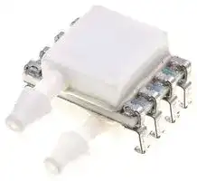

4525DO-DS3BK001DPL
Pressure Sensor, 1 psi, I2C Digital, Differential, 3.3 VDC, Dual Side Port
- Manufacturer: TE CONNECTIVITY
- Product type: Pressure Transducers
- Port Style: Dual Side Port
- Product Range: MS4525DO Series
- Sensor Output: I2C Digital
- Voltage Rating: 3.3VDC
- Operating Pressure Max: 1psi
- Pressure Measurement Type: Differential
| Delivery and price | |
|---|---|
| Units per pack | 10 |
| Price | 50.01 € |
| Current stock | 10+ |
| Lead time | 7 days |
## MS4525DO

## SPECIFICATIONS

- **PCB Mounted Digital Output Transducer**

- **Combination Temperature and Pressure**

- **I[2] C or SPI Protocol**

- **Differential, Gage, Absolute, Compound, &**

   - **Vacuum**

- **Temperature Compensated**

## FEATURES

- PSI Pressure Ranges

   - **3.3 or 5.0 VDC Supply Voltage**

   - **Low Power Option Available (standby  < 1µA)**

- PCB Mountable

- Digital Output

- Barbed Pressure Ports

## APPLICATIONS

- Blocked Filter Detection

- Altitude and Airspeed Measurements

- Medical Instruments

- Fire Suppression System

- Panel Meter

- Air Movement/Environmental Controls

- Pneumatic Controls

The MS4525DO is a small, ceramic based, PCB mounted pressure transducer from TE Connectivity.  The transducer is built using our proprietary UltraStable™ process and the latest CMOS sensor conditioning circuitry to create a low cost, high performance digital output pressure (14bit) and temperature (11bit) transducer designed to meet the strictest requirements from OEM customers.

The MS4525DO is fully calibrated and temperature compensated with a total error band (TEB) of less than 1.0% over the compensated pressure range.  The sensor operates from single supply of either 3.3 or 5.0VDC and requires a single external component for proper operation

The rugged ceramic transducer is available in side port, top port, and manifold mount and can measure absolute, gauge, differential, vacuum or compound pressure from 1 to 150psi. The 1/8” barbed pressure ports mate securely with 3/32” ID tubing.

04/2019

SENSOR SOLUTIONS /// MS4525DO

Page 1

MS4525DO

## STANDARD RANGES (PSI)

|**Pressure**|**Absolute**|**Gage**|**Differential**|**Compound**|**Vacuum**|**Option Availability**|
|---|---|---|---|---|---|---|
|1||DS, SS, TP, MM|DS, SS, TP, MM<br>DS, SS, TP, MM|DS, SS, TP, MM||-F, -L, -M|
|2||DS, SS, TP, MM|DS, SS, TP, MM<br>DS, SS, TP, MM|DS, SS, TP, MM||-F, -L, -M|
|5||DS, SS, TP, MM|DS, SS, TP, MM<br>DS, SS, TP ,MM|DS, SS, TP ,MM||-F, -L, -M|
|15|SS, TP|DS, SS, TP, MM|DS, SS, TP, MM<br>DS, MM|SS, TP|SS, TP, DS|-F, -L, -M|
|30|SS, TP|DS, SS, TP, MM|DS, SS, TP, MM<br>DS, MM|SS, TP||-F, -L, -M|
|50|SS, TP|DS, SS, TP, MM|DS, SS, TP, MM<br>DS, MM|SS, TP||-F, -L, -M|
|100|SS, TP|DS, SS, TP, MM|DS, SS, TP, MM<br>DS, MM|SS, TP||-F, -L, -M|
|150|SS, TP|DS, SS, TP, MM|DS, SS, TP, MM<br>DS, MM|SS, TP||-F, -L, -M|


**See Package Configurations:  DS= Dual Side Port, SS= Single Side Port, TP= Top Port, MM= Manifold Mount Only I[2] C Protocol is Available on “L” type Pin Styles; Reference Ordering Information for Details Pin Style “L” is only available SS and MM port types. Pin Style “C” is only available SS, TP and MM port types.**

## BLOCK DIAGRAM

04/2019

SENSOR SOLUTIONS /// MS4525DO

Page 2

MS4525DO

## ABSOLUTE MAXIMUM RATINGS

|**Parameter**|**Conditions**|**Min**|**Max**|**Unit**|**Notes**|
|---|---|---|---|---|---|
|Supply Voltage|TA= 25 °C|2.7|5.5|V||
|Output Current|TA= 25°C||3|mA||
|Storage Temperature||-40|+125|°C||
|Humidity|TA= 25°C||95|%RH|Non Condensing|
|Overpressure|TA= 25 °C, both Ports|Not to Exceed 300||psi||
|Burst Pressure|TA= 25 °C, Port 1|||psi|See Table 1|
|ESD|HBM|-4|+4|kV|EN 61000-4-2|
|Solder Temperature||250°C, 5 sec max.||||


**TABLE 1- BURST PRESSURE BY RANGE AND PACKAGE STYLE**

|**Range**|**DS**|**SS, TP, MM**|**Unit**|
|---|---|---|---|
|001|20|20|psi|
|002|20|20|psi|
|005|15|20|psi|
|015|45|90|psi|
|030|90|200|psi|
|050|150|300|psi|
|100|300|300|psi|
|150|300|300|psi|


## ENVIRONMENTAL SPECIFICATIONS

|**Parameter**|**Conditions**|
|---|---|
|Mechanical Shock|Mil Spec 202F, Method 213B, Condition C, 3 Drops|
|Mechanical Vibration|Mil Spec 202F, Method 214A, Condition 1E, 1Hr Each Axis|
|Thermal Shock|100 Cycles over Storage Temperature, 30 minute dwell|
|Life|1 Million FS Cycles|
|MTTF|>10Yrs, 70 ºC, 1.188 Million Pressure Cycles,  120%FS Pressure|


04/2019

SENSOR SOLUTIONS /// MS4525DO

Page 3

MS4525DO

## PERFORMANCE SPECIFICATIONS

## **Supply Voltage[1] : 5.0V or 3.3 VDC**

## **Reference Temperature: 25°C (unless otherwise specified)**

|**PARAMETERS**|**MIN**|**TYP**||**MAX**|**UNITS**|**NOTES**|
|---|---|---|---|---|---|---|
|Accuracy|-0.25|||0.25|% SPAN|2|
|Total Error Band|-1|||1|% SPAN|3,7|
|Burst pressure||SEE TABLE 1|||||
|Common mode pressure||NOT TO EXCEED 300 PSI|||||
|Load Resistance (RL)|10||||kΩ||
|Long term stability (offset & span)||±0.5|||% SPAN||
|Compensated Temperature|-10|||85|oC||
|Operating Temperature|-25|||105|oC||
|Weight||3|||grams||
|Update time||0.5|||ms|6|
|Start time to data ready||||8.4|ms|6|
|Solder temperature||250oC MAX 5 SEC.|||||
|Media|Non-Corrosive Dry Gases Compatible with Ceramic, Silicon, Borosilicate Glass,||||||
||RTV, Gold, Aluminum and Epoxy.|||See “Wetted Material by Port||Designation” chart|
|||||below.|||


## **Notes**

1. Proper operation requires an external capacitor placed as shown in Connection Diagram.  Output is not ratiometric to supply voltage.

2. The maximum deviation from a best fit straight line (BFSL) fitted to the output measured over the pressure range at 25C.  Includes all errors due to pressure non linearity, hysteresis, and non repeatability.

3. Total pressure error band includes all accuracy errors, thermal errors over the compensated temperature range and span and offset calibration tolerances.  For ideal sensor output with respect to input pressure and temperature, reference Transfer Function charts below. TEB values are valid only at the calibrated supply voltage.

4. The deviation from a best fit straight line (BFSL) fitted to the output measured over the compensated temperature range.

5. For errors beyond the compensated temperature range, see Extended Temperature Multiplier chart below.

6. Start time to data ready is the time to get valid data after POR (power on reset). The time to get subsequent valid data is then specified by the update time specification.

7. This product can be configured for custom OEM requirements, contact factory for lower power consumption or higher accuracy.

## CONNECTION DIAGRAM

**==> picture [33 x 36] intentionally omitted <==**

## **Notes**

1. Place 100nF capacitor between Supply and GND to within 2 cm of sensor.

04/2019

SENSOR SOLUTIONS /// MS4525DO

Page 4

MS4525DO

## PRESSURE AND TEMPERATURE TRANSFER FUNCTION

## **Sensor Output at Significant Percentages**

|**% of Count**|**Output Type A (psi)**|**Output Type B (psi)**|**Digital Counts (decimal)**|**Digital Counts (hex)**|
|---|---|---|---|---|
|**0**|PMIN-(PMAX-PMIN)*10/80|PMIN-(PMAX-PMIN)*5/90|0|0X0000|
|**5**||PMIN|819|0X0333|
|**10**|PMIN||1638|0X0666|
|**50**|||8192|0X2000|
|**90**|PMAX||14746|0X399A|
|**95**||PMAX|15563|0X3CCB|
|**100**|PMAX+(PMAX-PMIN)*10/80|PMAX+(PMAX-PMIN)*5/90|16383|0X3FFF|


## **Temperature Output vs Counts**

|**OUTPUT(°C)**|**Digital Count(decimal)**|**Digital Counts(hex)**|
|---|---|---|
|**-50**|0|0X0000|
|**0**|511|0X01FF|
|**10**|614|0X0266|
|**25**|767|0X02FF|
|**50**|1023|0X03FF|
|**85**|1381|0X0565|
|**150**|2047|0X07FF|


04/2019

SENSOR SOLUTIONS /// MS4525DO

Page 5

MS4525DO

|**% of Count**|**Output Type A(psi)**|**Output Type B(psi)**|**Digital Counts(decimal)**|**Digital Counts(hex)**|
|---|---|---|---|---|
|**0**|1.6875|0.833|0|0X0000|
|**5**||0|819|0X0333|
|**10**|0||1638|0X0666|
|**50**|||8192|0X2000|
|**90**|-15||14746|0X399A|
|**95**||-15|15563|0X3CCB|
|**100**|||16383|0X3FFF|


|**OUTPUT(°C)**|**Digital Count(decimal)**|**Digital Counts(hex)**|
|---|---|---|
|**-50**|0|0X0000|
|**0**|511|0X01FF|
|**10**|614|0X0266|
|**25**|767|0X02FF|
|**50**|1023|0X03FF|
|**85**|1381|0X0565|
|**150**|2047|0X07FF|


04/2019

SENSOR SOLUTIONS /// MS4525DO

Page 6

MS4525DO

EXTENDED TEMPERATURE MULTIPLIER CHART

**==> picture [267 x 137] intentionally omitted <==**

**----- Start of picture text -----**<br>
2.5<br>2.0<br>1.5<br>1.0<br>0.5<br>0.0<br>-25 -10  5 20 35 50 65 80 95 110 125<br>**----- End of picture text -----**<br>


PACKAGE, PINOUT & PRESSURE TYPE CONFIGURATION

**==> picture [71 x 95] intentionally omitted <==**

**==> picture [109 x 89] intentionally omitted <==**

**==> picture [69 x 89] intentionally omitted <==**

**==> picture [72 x 90] intentionally omitted <==**

**==> picture [109 x 56] intentionally omitted <==**

**==> picture [69 x 56] intentionally omitted <==**

**==> picture [72 x 56] intentionally omitted <==**

**==> picture [72 x 56] intentionally omitted <==**

**==> picture [69 x 56] intentionally omitted <==**

04/2019

SENSOR SOLUTIONS /// MS4525DO

Page 7

MS4525DO

|**Pin Name**|**Pin**|**Function**|
|---|---|---|
|GND|1|Ground|
|SUPPLY|2|Positive Supply Voltage|
|SDA            MISO|<br>3|I2C Data                          SPI Data|
|SCL            SCLK|<br>4|I2C Clock                         SPI Clock|
|INT                  SS|<br>5|I2C Interrupt            SPI Chip Select|
||6-8|No Connection|


INT is not available for Pin Style “L” models

|**Pressure Type**|<br>**Pmin**|**Pmax**|**Description**|
|---|---|---|---|
|Absolute|0psiA|+Prange|Output is proportional to the difference between 0psiA (Pmin) and pressure|
||||applied to Port 1.|
|Differential/|-Prange|+Prange|Output is proportional to the difference between Port 1 and Port 2.  Output|
|Bidirectional|||swings positive when Port 1> Port 2.  Output is 50% of total counts when|
||||Port 1=Port 2.|
|Gauge|0psiG|+Prange|Output is proportional to the difference between 0psiG (Pmin) and Port 1.|
||||Output swings positive when Port 1> Port 2.|
|Vacuum|-15psiG|+0psiG|Output is inversely proportional to the difference between -15psiG pressure|
||||(Pmin) and pressure applied to Port 1.|
|Compound|-15psiG|+Prange|Output is proportional to the difference between -15psiG pressure (Pmin) and|
||||pressure applied to Port 1.|


*Prange is equal to the maximum full scale pressure specified in the ordering information.

Standard ranges (psi) by port style

## WETTED MATERIAL BY PORT DESIGNATION

|||||**Material**|**Material**||||
|---|---|---|---|---|---|---|---|---|
|Style|**Port**|**Ceramic**|<br>**Silicon**|<br>**Borosilicate Glass**|**RTV**|**Gold**|**Aluminum**|<br>**Epoxy**|
|DS, MM|Port 1<br>Port 2|X<br>X|X<br>X|X<br>X|X<br>X|X|X|X<br>X|
|SS, TP, SM|Port 1|X|X|X|X|X|X|X|
|‘X’ indicates Wetted Material|||||||||


04/2019

SENSOR SOLUTIONS /// MS4525DO

Page 8

MS4525DO

## I[2] C INTERFACE

04/2019

SENSOR SOLUTIONS /// MS4525DO

Page 9

MS4525DO

## SPI INTERFACE

04/2019

SENSOR SOLUTIONS /// MS4525DO

Page 10

MS4525DO

## DIMENSIONS

Model: MS4525DO-DSvoixxxyP

**==> picture [100 x 112] intentionally omitted <==**

**==> picture [219 x 127] intentionally omitted <==**

Model: MS4525DO-DSvoixxxyS

**==> picture [106 x 127] intentionally omitted <==**

**==> picture [584 x 164] intentionally omitted <==**

04/2019

SENSOR SOLUTIONS /// MS4525DO

Page 11

MS4525DO

Model: MS4525DO-SSvoixxxyP

**==> picture [100 x 112] intentionally omitted <==**

**==> picture [78 x 76] intentionally omitted <==**

**==> picture [121 x 99] intentionally omitted <==**

Model: MS4525DO-SSvoixxxyS

**==> picture [114 x 140] intentionally omitted <==**

**==> picture [246 x 116] intentionally omitted <==**

04/2019

SENSOR SOLUTIONS /// MS4525DO

Page 12

MS4525DO

Model: MS4525DO-TPvoixxxyP

**==> picture [86 x 67] intentionally omitted <==**

**==> picture [86 x 125] intentionally omitted <==**

**==> picture [110 x 152] intentionally omitted <==**

Model: MS4525DO-TPvoixxxyS

**==> picture [87 x 83] intentionally omitted <==**

**==> picture [87 x 106] intentionally omitted <==**

**==> picture [111 x 134] intentionally omitted <==**

04/2019

SENSOR SOLUTIONS /// MS4525DO

Page 13

MS4525DO

Model: MS4525DO-SSvoixxxyL

**==> picture [118 x 33] intentionally omitted <==**

**==> picture [196 x 188] intentionally omitted <==**

**==> picture [92 x 155] intentionally omitted <==**

Model: MS4525DO-MMvoixxxyL

**==> picture [67 x 51] intentionally omitted <==**

**==> picture [294 x 186] intentionally omitted <==**

04/2019

SENSOR SOLUTIONS /// MS4525DO

Page 14

MS4525DO

Model: MS4525DO-MMvoixxxyP

**==> picture [173 x 93] intentionally omitted <==**

**==> picture [90 x 81] intentionally omitted <==**

**==> picture [91 x 81] intentionally omitted <==**

**==> picture [63 x 32] intentionally omitted <==**

Model: MS4525DO-MMvoixxxyS

**==> picture [177 x 94] intentionally omitted <==**

**==> picture [99 x 103] intentionally omitted <==**

**==> picture [32 x 57] intentionally omitted <==**

**==> picture [98 x 98] intentionally omitted <==**

04/2019

SENSOR SOLUTIONS /// MS4525DO

Page 15

MS4525DO

Model: MS4525DO-SSvoixxxyC

**==> picture [243 x 295] intentionally omitted <==**

Model: MS4525DO-TPvoixxxyC

**==> picture [69 x 56] intentionally omitted <==**

**==> picture [172 x 165] intentionally omitted <==**

04/2019

SENSOR SOLUTIONS /// MS4525DO

Page 16

MS4525DO

Model: MS4525DO-MMvoixxxyC

**==> picture [132 x 105] intentionally omitted <==**

**==> picture [81 x 31] intentionally omitted <==**

**==> picture [120 x 76] intentionally omitted <==**

**==> picture [132 x 99] intentionally omitted <==**

04/2019

SENSOR SOLUTIONS /// MS4525DO

Page 17

MS4525DO

## APPLICATION NOTES

Measurement Specialties offers a comprehensive selection of product support documentation.

## _MS45xx Series Application Note_

- Bypass Capacitor Selection

- Pressure Hose Recommendations

- PCB Layout Recommendations

## _Interfacing to MEAS Digital Pressure Modules_

- I[2] C or SPI Protocol Description

- Data Fetch, Measurement Request Commands

- Timing Diagrams

## _Configuration, POR and Power Consumption_

- Standard and Low Power Configuration

- Power On Reset (POR)

- Current Consumption by Sampling Frequency

## AVAILABLE OPTIONS

## **Gel Coat (-F Option)**

The MS4525DO is designed for non-ionic and clean dry air applications.  Select this option for added protection in high humidity or slightly corrosive environments with the application of a silicone gel elastomer to sensor and ASIC.  For questions concerning media compatibility, contact the factory.

## **Low Power (-L Option)**

Select this option for battery powered or handheld device applications.  In this configuration, the sensor and calibration microcontroller are powered down, drawing a current of ~ 0.6uA (Vs=5.0 VDC).  When the master sends a **Read MR** (measurement request) command (I[2] C or SPI); the sensor is “awaken” and begins the measurement cycle; data is then placed onto the output registers.  The sensor and calibration microcontroller are powered down again, awaiting the **Read DF** (data fetch) command from the master.

04/2019

SENSOR SOLUTIONS /// MS4525DO

Page 18

MS4525DO

## ORDERING INFORMATION

**==> picture [530 x 503] intentionally omitted <==**

**----- Start of picture text -----**<br>
4525DO – DS 3 B K 030 D P M<br>Package Type Option Type<br>SS  Single Sideport  [Blank] No Option<br>DS  Dual Sideport  F  Gel Coating<br>TP  Top Port  L  Low Power<br>MM  Manifold Mount  M  Gel Coat & Low Power<br>Supply Voltage  Pin Type<br>3  3.3 VDC P  Thru Hole<br>5  5.0 VDC S  J Lead<br>L  In Line<br>Output Type  C  Castellation<br>A  10% to 90%<br>B  5% to 95%  Pressure Type<br>D  Differential<br>Interface Type  G  Gauge<br>V  Vacuum<br>I  I [2] C (Addr. 0x28H)  A  Absolute<br>C  Compound<br>J  I [2] C (Addr. 0x36H)<br>== Pressure Range [psi]<br>K  I [2] C (Addr. 0x46H)  001<br>002<br>S  SPI (Not available for ‘L’ pin Style)<br>005<br>0  I [2] C (Addr. 0x48H)  015<br>030<br>:  :  050<br>100<br>9  I [2] C (Addr. 0x51H)<br>150<br>= =<br>NORTH AMERICA EUROPE ASIA<br>Measurement Specialties, Inc.,  Measurement Specialties (Europe), Ltd.,  Measurement Specialties (China) Ltd.,<br>a TE Connectivity company Tel:  800-522-6752  a TE Connectivity Company Tel:  +31 73 624 6999  a TE Connectivity company Tel:  0400-820-6015<br>Email: customercare.frmt@te.com Email: customercare.bevx@te.com Email: customercare.shzn@te.com<br>**----- End of picture text -----**<br>


## **TE.com/sensorsolutions**

Measurement Specialties, Inc., a TE Connectivity company.

Measurement Specialties, TE Connectivity, TE Connectivity (logo) and EVERY CONNECTION COUNTS are trademarks. All other logos, products and/or company names referred to herein might be trademarks of their respective owners.

The information given herein, including drawings, illustrations and schematics which are intended for illustration purposes only, is believed to be reliable. However, TE Connectivity makes no warranties as to its accuracy or completeness and disclaims any liability in connection with its use. TE Connectivity‘s obligations shall only be as set forth in TE Connectivity‘s Standard Terms and Conditions of Sale for this product and in no case will TE Connectivity be liable for any incidental, indirect or consequential damages arising out of the sale, resale, use or misuse of the product. Users of TE Connectivity products should make their own evaluation to determine the suitability of each such product for the specific application.

© 2015 TE Connectivity Ltd. family of companies All Rights Reserved.

04/2019

SENSOR SOLUTIONS /// MS4525DO

Page 19
Updated at February 9, 2023
TE Connectivity is a globally recognized engineering and manufacturing leader, specializing in highly reliable connectivity and sensing solutions. Renowned for innovation and durability, their components are engineered to perform in the most demanding environments, supporting critical advancements in industrial equipment, data communications, and automotive systems. Our extensive selection of TE Connectivity products is anchored by their industry-leading connector portfolio. We carry a comprehensive array of terminal blocks and accessories, including wire-to-board, pluggable, standard, and barrier configurations, alongside robust backplane connectors designed to ensure secure and efficient power and data transmission in complex circuit designs. Beyond physical connections, TE Connectivity is a premier manufacturer of precision sensors, antennas, and electromechanical switching components. Our inventory features a wide variety of RF antennas and highly accurate pressure, temperature, and force transducers. Additionally, we provide an expansive range of TE's dependable relays, encompassing automotive, power, and signal variants, alongside essential passive components like shielding gaskets and RF inductors to fully support your engineering requirements.
About Novapart
Novapart is a B2B electronic component broker specialising in stock shortages and cost reduction. We source hard-to-find parts and identify compliant alternatives across a catalogue of 410,000+ components from 500+ manufacturers.
Learn more →Stock Shortage Specialist
When a component is unavailable, discontinued or has an unacceptable lead time, we tap into our network of vetted European and Asian distributors to source what you need — without compromising on quality or traceability.
Request a quote →Compliant Alternatives
We identify pin-to-pin, electrically equivalent substitutes that meet the same certifications (RoHS, AEC-Q100, REACH) as your original specification — validated against datasheets, not just part numbers. Often at a lower cost.
BOM Analysis service →