
Image not available
Illustrative purposes only

44.62.7.006.4000
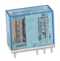
General Purpose Relay, 44 Series, Power, DPDT, 6 VDC, 10 A
⚠️ Reference pricing provided. In case of supply shortages, we will connect you with our trusted procurement partners to ensure your project's continuity.
- Manufacturer: FINDER
- Product type: Power Relays
- Contact Configuration:DPDT; Coil Voltage:6VDC; Contact Current:10A; Product Range:44 Series; Relay Mounting:Through Hole; Coil Type:-; Contact Voltage VAC:250VAC; Relay Terminals:Solder; Contact
- SVHC: No SVHC (25-Jun-2025)
- Coil Type: -
- Coil Voltage: 6VDC
- Product Range: 44 Series
- Relay Mounting: Through Hole
- Coil Resistance: 75ohm
- Contact Current: 10A
- Relay Terminals: Solder
- Contact Material: Silver Tin Oxide
- Contact Voltage VAC: 250VAC
- Contact Voltage VDC: -
- Contact Configuration: DPDT
| Delivery and price | |
|---|---|
| Units per pack | 50 |
| Price | 4.6 € |
| Current stock | 10+ |
| Lead time | 30 days |
Datasheet

**44 SERIES**

**A**

## **2 CO power relays with high separation between adjacent contacts Direct PCB or socket mount Type 44.52**

**==> picture [198 x 137] intentionally omitted <==**

**----- Start of picture text -----**<br>
44.52 44.62<br>a, t pd /<br>• 2 CO 6 A • 2 CO 10 A<br>• PCB or 95 series sockets • PCB or 95 series sockets<br>**----- End of picture text -----**<br>


**==> picture [162 x 104] intentionally omitted <==**

**----- Start of picture text -----**<br>
 - 2 CO 6 A (5 mm pin pitch)<br>Type 44.62<br> - 2 CO 10 A (5 mm pin pitch)<br>• DC coils (Standard or sensitive)<br>• Cadmium Free contact materials<br>• 8 mm, 6 kV (1.2/50 μs) isolation, coil-contacts<br>• UL Listing (certain relay/socket combinations)<br>• 95 series sockets for PCB or 35 mm rail<br>mounting (EN 60715) with Screw, Screwless or<br>Push-in terminals<br>**----- End of picture text -----**<br>


|**2 CO power relays with high separation**<br>**between adjacent contacts**<br>**Direct PCB or socket mount**<br>**Type 44.52**<br>- 2 CO 6 A (5 mm pin pitch)<br>**Type 44.62**<br>- 2 CO 10 A (5 mm pin pitch)<br>• DC coils (Standard or sensitive)DC coils (Standard or sensitive)<br>• Cadmium Free contact materialsCadmium Free contact materials<br>• 8 mm, 6 kV (1.2/50 μs) isolation, coil-contacts8 mm, 6 kV (1.2/50 μs) isolation, coil-contacts<br>• UL Listing (certain relay/socket combinations)UL Listing (certain relay/socket combinations)<br>• 95 series sockets for PCB or 35 mm rail95 series sockets for PCB or 35 mm rail<br>mounting (EN 60715) with Screw, Screwless or<br>Push-in terminals<br>•Coil Indication and EMC suppression modules<br>99 series and Timer module 86.30 options<br>•Environmental protection:<br>RT II - flux proof (Standard)<br>25<br>0.4<br>1<br>5<br>29<br>12.4<br>_For ULratings see:_<br>_“General technical information” page_V<br>**Contact specification**<br>Contact configuration|**44.52**<br>• 2 CO 6 A2 CO 6 A<br>• PCB or 95 series socketsPCB or 95 series sockets<br>a,<br>t|**44.52**<br>• 2 CO 6 A2 CO 6 A<br>• PCB or 95 series socketsPCB or 95 series sockets<br>a,<br>t|**44.62**<br>• 2 CO 10 A2 CO 10 A<br>• PCB or 95 series socketsPCB or 95 series sockets<br>pd<br>/|
|---|---|---|---|
||Copper side view<br>2 CO (DPDT)<br>Al<br>12 1114<br>r~~oy~~<br>a9 8<br>~~a~~es<br>A2<br>22 21 24<br>5.5<br>elie.<br>@2g<br>2.5<br>20<br>6"||Copper side view<br>2 CO (DPDT)<br>Al<br>12 1114<br>fey<br>89 F<br>~~ca~~ess<br>A2<br>22 21 24<br>55<br>Hie. eed<br>2.5<br>20<br>6,"|
|Rated current/Maximum peak current<br>A|6/10||10/20|
|Rated voltage/<br>Maximum switchingvoltage<br>V AC|250/400||250/400|
|Rated load AC1<br>VA|1500||2500|
|Rated load AC15 (230 V AC)<br>VA|250||500|
|Single phase motor rating (230 V AC)<br>kW|0.185||0.37|
|Breaking capacity DC1: 30/110/220 V<br>A|6/0.3/0.13||10/0.3/0.13|
|Minimum switching load<br>mW (V/mA)|300 (5/5)||300 (5/5)|
|Standard contact material<br>**Coil specification**<br>Nominal voltage (UN)<br>V AC (50/60 Hz)<br>V DC|AgNi<br>—||AgNi<br>—|
||6 - 9 - 12 - 14 - 24 - 28 - 48 - 60 - 110 - 125|||
|Rated power AC/DC/sens. DC<br>VA (50 Hz)/W/W|—/0.65/0.5||—/0.65/0.5|
|Operating range<br>AC<br>DC/sens. DC|—||—|
||(0.73…1.5)UN/ (0.73…1.7)UN||(0.73…1.5)UN/ (0.8…1.7)UN|
|Holding voltage<br>AC/DC|—/0.4 UN||—/0.4 UN|
|Must drop-out voltage<br>AC/DC<br>**Technical data**<br>Mechanical life AC/DC<br>cycles|—/0.1 UN<br>—/20 · 106||—/0.1 UN<br>—/20 · 106|
|Electrical life at rated load AC1<br>cycles|150 · 103||100 · 103|
|Operate/release time<br>ms|8/5 - (12/5 sensitive)||8/5 - (12/5 sensitive)|
|Insulation between coil<br>and contacts(1.2/50μs)<br>kV|6(8 mm)||6(8 mm)|
|Dielectric strength<br>between open contacts<br>V AC|1000||1000|
|Ambient temperature range<br>°C|–40…+85||–40…+85|
|Environmental protection|RT II||RT II|
|**Approvals**(according to type)|@EL|EL&®@RINAAis||


**1**

**44 SERIES**

## **Ordering information**

Example:  44 series PCB relay, 2 CO 10 A contacts, 24 V DC coil.

**A**

**A B C D**

## **4 4 . 6 2 . 9 . 0 2 4 . 0 0 0 0**

## **Series**

## **Type**

- 5 =  PCB - 5 mm pinning

6 =  PCB - 5 mm pinning

## **A: Contact material**

0 = Standard AgNi

4 =  AgSnO2 for 44.62 only

- 5 =  AgNi + Au for 44.52 only

## **D: Special versions**

0 =  Flux proof (RT II)

## **C: Options**

0 =  None

## **No. of poles**

2 =  2 pole for

44.52, 6 A

## **B: Contact circuit**

- 0 =  CO (DPDT)

44.62, 10 A

## **Coil version**

7 =  Sensitive DC

9 =  DC

## **Coil voltage**

See coil specifications

**Selecting features and options: only combinations in the same row are possible.** Preferred selections for best availability are shown in **bold** .

|**Type**|**Coil version**|**A**|**B**|**C**|**D**|
|---|---|---|---|---|---|
|44.52|DC - sens. DC|**0**- 5|**0**|**0**|**0**|
|44.62|DC - sens. DC|**0**- 4|**0**|**0**|**0**|


## **Technical data**

|**Insulation according to EN 61810-1**|**Insulation according to EN 61810-1**|**Insulation according to EN 61810-1**|**Insulation according to EN 61810-1**|
|---|---|---|---|
|Nominal voltage of supply system<br>V AC||230/400||
|Rated insulation voltage<br>V AC||250|400|
|Pollution degree||3|2|
|**Insulation between coil and contact set**||||
|Type of Insulation||Reinforced (8 mm)||
|Overvoltage category||III||
|Rated impulse voltage<br>kV (1.2/50 μs)||6||
|Dielectric strength<br>V AC||4000||
|**Insulation between adjacent contacts**||||
|Type of insulation||Basic||
|Overvoltage category||III||
|Rated impulse voltage<br>kV (1.2/50 μs)||4||
|Dielectric strength<br>V AC||2500||
|**Insulation between open contacts**||||
|Type of disconnection||Micro-disconnection||
|Dielectric strength<br>V AC/kV (1.2/50 μs)||1000/1.5||
|**Conducted disturbance immunity**||||
|Burst (5…50)ns, 5 kHz, on A1 - A2||EN 61000-4-4|level 4 (4 kV)|
|Surge (1.2/50 μs) on A1 - A2 (differential mode)||EN 61000-4-5|level 3 (2 kV)|
|**Other data**||||
|Bounce time: NO/NC<br>ms||4/4||
|Vibration resistance (5…55)Hz: NO/NC<br>g||15/12||
|Shock resistance|g|16||
|Power lost to the environment|without contact current<br>W|0.6||
||with rated current<br>W|1.2 (44.52)|2.7 (44.62)|
|Recommended distance between relays mounted on PCB<br>mm||≥5||


**2**

**44 SERIES**

**A**

## **Contact specification**

**==> picture [145 x 8] intentionally omitted <==**

**----- Start of picture text -----**<br>
F 44 - Electrical life (AC) v contact current<br>**----- End of picture text -----**<br>


**==> picture [215 x 108] intentionally omitted <==**

**----- Start of picture text -----**<br>
Resistive load - cosφ = 1<br>Inductive load - cosφ = 0.4<br>limit for 44.52<br>Cycles<br>**----- End of picture text -----**<br>


## **H 44 - Maximum DC1 breaking capacity**

**==> picture [206 x 120] intentionally omitted <==**

**----- Start of picture text -----**<br>
44.62 current limit<br>44.52 current limit<br>2 contacts in series<br>single contact<br>DC voltage (V)<br>DC breaking current (A)<br>**----- End of picture text -----**<br>


- When switching a resistive load (DC1) having voltage and current values under the curve, an electrical life of ≥ 100 · 10[3] can be expected.

- In the case of DC13 loads, the connection of a diode in parallel with the load will permit a similar electrical life as for a DC1 load.

Note: the release time for the load will be increased.

## **Coil specifications**

## **DC coil data - 0.65 W standard**

**==> picture [252 x 54] intentionally omitted <==**

**----- Start of picture text -----**<br>
Nominal  Coil code Operating range Resistance Rated coil<br>voltage consumption<br>UN Umin Umax R I at UN<br>V V V Ω mA<br>**----- End of picture text -----**<br>


|Nominal<br>voltage<br>UN<br>V|Coil code|Operating range<br>Umin<br>Umax<br>V<br>V|Operating range<br>Umin<br>Umax<br>V<br>V|Resistance<br>R<br>Ω|Rated coil<br>consumption<br>Iat UN<br>mA|
|---|---|---|---|---|---|
|6|**9**.006|4.4|9|55|109|
|9|**9**.009|6.6|13.5|125|72|
|12|**9**.012|8.8|18|220|55|
|14|**9**.014|10.2|21|300|47|
|24|**9**.024|17.5|36|900|27|
|28|**9**.028|20.5|42|1200|23|
|48|**9**.048|35|72|3500|14|
|60|**9**.060|43.8|90|5500|11|
|110|**9**.110|80.3|165|18000|6.2|
|125|**9**.125|91.2|188|23500|5.3|


## **DC coil data - 0.5 W sensitive**

**==> picture [252 x 54] intentionally omitted <==**

**----- Start of picture text -----**<br>
Nominal  Coil code Operating range Resistance Rated coil<br>voltage consumption<br>UN Umin Umax R I at UN<br>V V V Ω mA<br>**----- End of picture text -----**<br>


|Nominal<br>voltage<br>UN<br>V|Coil code|Operating range<br>Umin<br>Umax<br>V<br>V|Operating range<br>Umin<br>Umax<br>V<br>V|Resistance<br>R<br>Ω|Rated coil<br>consumption<br>Iat UN<br>mA|
|---|---|---|---|---|---|
|6|**7**.006|4.4|10.2|75|80|
|9|**7**.009|6.6|15.3|160|56|
|12|**7**.012|8.8|20.4|300|40|
|14|**7**.014|10.2|23.8|400|35|
|24|**7**.024|17.5|40.8|1200|20|
|28|**7**.028|20.5|47.6|1600|17.5|
|48|**7**.048|35|81.6|4800|10|
|60|**7**.060|43.8|102|7200|8.4|
|110|**7**.110|80.3|187|23500|4.7|
|125|**7**.125|100|219|32000|3.9|


- Umin = 0.8 UN for 44.62

## **R 44 - DC coil operating range v ambient temperature** Standard coil

**==> picture [189 x 102] intentionally omitted <==**

**----- Start of picture text -----**<br>
1<br>2<br>**----- End of picture text -----**<br>


**==> picture [105 x 8] intentionally omitted <==**

**----- Start of picture text -----**<br>
1 -   Max. permitted coil voltage.<br>**----- End of picture text -----**<br>


**2 -** Min. pick-up voltage with coil at ambient temperature.

**R 44 - DC coil operating range v ambient temperature**

Sensitive coil

**==> picture [189 x 103] intentionally omitted <==**

**----- Start of picture text -----**<br>
1<br>2<br>**----- End of picture text -----**<br>


**1 -** Max. permitted coil voltage.

**2 -** Min. pick-up voltage with coil at ambient temperature.

**3**

**44 SERIES**

**A**

**==> picture [498 x 612] intentionally omitted <==**

**----- Start of picture text -----**<br>
|||||||
|---|---|---|---|---|---|
|Module|Socket|Relay|Description|Mounting|Accessories|
|99.02|95.P5|44.52|Push-in terminal sockets|Panel or 35 mm rail|- Coil indication and EMC|
|PreSy|7|44.62|-For fast cable connection|(EN 60715) mount|suppression modules|
|3|: = a|“A|=|- Top terminals - Contacts|- Jumper link|
|95.P5|- Bottom terminals - Coil|- Timer modules|
|See page 5|- Plastic retaining and release|
|clip|
|Module|Socket|Relay|Description|Mounting|Accessories|
|99.02|95.05|44.52|Screw terminal (Box clamp) socket|Panel or 35 mm rail|- Coil indication and EMC|
|44.62|- Top terminals - Contacts|(EN 60715) mount|suppression modules|
|- Bottom terminals - Coil|- Jumper link|
|- Timer modules|
|95.05|
|- Plastic retaining and release|
|See page 7|
|“ee|clip|
|Module|Socket|Relay|Description|Mounting|Accessories|
|99.02|95.55|44.52|Screwless terminal socket|Panel or 35 mm rail|- Coil indication and EMC|
|ee|44.62|- For fast cable connections|(EN 60715) mount|suppression modules|
|- Top terminals - Contacts|- Timer modules|
|- Bottom terminals - Coil|- Plastic retaining and release|
|clip|
|95.55|
|See page 8|
|Module|Socket|Relay|Description|Mounting|Accessories|
|99.80|95.85.3|44.52|Screw terminal (Box clamp) socket|Panel or 35 mm rail|- Coil indication and EMC|
|44.62|(EN 60715) mount|suppression modules|
|- Plastic retaining and release|
|clip|
|95.85.3|
|See page 9|
|Module|Socket|Relay|Description|Mounting|Accessories|
|99.80|95.95.3|44.52|Screw terminal (Box clamp) socket|Panel or 35 mm rail|- Coil indication and EMC|
|44.62|- Top terminals - Contacts|(EN 60715) mount|suppression modules|
|- Bottom terminals - Coil|- Plastic retaining and release|
|clip|
|95.95.3|
|See page 10|
|Module|Socket|Relay|Description|Mounting|Accessories|
|—|95.65|44.52|Screw terminal (Box clamp) socket|Panel or 35 mm rail|- Metal retaining clip|
|44.62|(EN 60715) mount|
|95.65|
|See page 11|
|Module|Socket|Relay|Description|Mounting|Accessories|
|—|95.15.2|44.52|PCB socket|PCB mounting|- Metal retaining clip|
|95.15.2|44.62|
|See page 12|

**----- End of picture text -----**<br>


Top terminals

Bottom terminals

**4**

**44 SERIES**

|**Push-in terminal socket**panel or 35 mm rail mount<br>**95.P5**<br>For relay type<br>44.52, 44.62<br>**Accessories**<br>Metal retainingclip<br>095.71|**95.P5**<br>44.52, 44.62<br>095.71|**95.P5**<br>44.52, 44.62<br>095.71|
|---|---|---|
|Plastic retaining and release clip<br>(supplied with socket -packagingcode SPA)<br>095.91.3|095.91.3||
|8-way jumper link<br>097.58|097.58||
|2-way jumper link(12.5 mmpitch)<br>097.52|097.52||
|2-way jumper link(4.6 mmpitch)<br>097.42|097.42||
|Marker tagholder(for tags 060.48 and 060.72 types)<br>097.00|097.00||
|Identification tag<br>095.00.4|095.00.4||
|Modules(see table below)<br>99.02|99.02||
|Timer modules(see table below)<br>86.30|86.30||
|Sheet of marker tags for plastic retaining and release clip<br>095.91.3 and for marker tag holder 097.00, 48 tags,<br>6 x 12 mm,for CEMBRE's thermal transfertprinter<br>060.48|060.48||
|Sheet of marker tags for plastic retaining and release<br>clip 095.91.3 and for marker tag holder 097.00, 72 tags,<br>6 x 12 mm, for plotter printing<br>060.72<br>**Technical data**<br>Rated values<br>10 A - 250 V|060.72<br>10 A - 250 V||
|Dielectric strength<br>6 kV|6 kV(1.2/50µs)between coil and contacts||
|Protection category<br>IP 20|IP 20||
|Ambient temperature<br>°C –40…+70|–40…+70(see diagram L95)||
|Wire striplength<br>mm 8|8||
|Min. wire size for 95.P5 socket<br>solid wire<br>mm2 0.5<br>AWG 21|solid wire|stranded wire|
||0.5|0.5|
||21|21|
|Max. wire size for 95.P5 socket<br>solid wire<br>mm2 2 x 1.5 / 1 x 2.5<br>AWG 2 x 18 / 1 x 14<br>~~Po~~|solid wire|stranded wire|
||2 x 1.5 / 1 x 2.5<br>~~Po~~|2 x 1.5 / 1 x 2.5|
||2 x 18 / 1 x 14|2 x 18 / 1 x 14|


## **L 95 - Total socket current vs ambient temperature**

**==> picture [304 x 36] intentionally omitted <==**

**----- Start of picture text -----**<br>
95.P5 71 . 7<br>8-way jumper link  for 95.P5 socket 097.58<br>Rated values 10 A - 250 V<br>**----- End of picture text -----**<br>


**==> picture [25 x 7] intentionally omitted <==**

**----- Start of picture text -----**<br>
097.58<br>**----- End of picture text -----**<br>


**==> picture [304 x 19] intentionally omitted <==**

**----- Start of picture text -----**<br>
2-way jumper link  for 95.P5 socket 097.52<br>Rated values 10 A - 250 V<br>**----- End of picture text -----**<br>


**==> picture [25 x 6] intentionally omitted <==**

**----- Start of picture text -----**<br>
097.52<br>**----- End of picture text -----**<br>


**5**

**44 SERIES**

**==> picture [10 x 10] intentionally omitted <==**

**----- Start of picture text -----**<br>
A<br>**----- End of picture text -----**<br>


**==> picture [25 x 7] intentionally omitted <==**

**----- Start of picture text -----**<br>
097.42<br>**----- End of picture text -----**<br>


**2-way jumper link** for 95.P5 socket 097.42 Rated values 10 A - 250 V 2 fit for 95.P5 sockets 097.00

**Marker tag holder** for 95.P5 sockets

**097.00**

## **86 series timer modules**

**==> picture [20 x 6] intentionally omitted <==**

**----- Start of picture text -----**<br>
86.30<br>**----- End of picture text -----**<br>


‘PAL. **99.02** eA Approvals (according to type):

DC Modules with non-standard polarity (+A2) on request.

|(12…24)V AC/DC;Bi-function: AI,DI; (0.05 s…100 h)|86.30.0.024.0000|
|---|---|
|(110…125)V AC;Bi-function: AI,DI; (0.05 s…100 h)|86.30.8.120.0000|
|(230…240)V AC;Bi-function: AI,DI; (0.05 s…100 h)<br>Approvals (according to type):<br>CE FL & Wis|86.30.8.240.0000|
|**99.02 coil indication and EMC suppression modules**for 95.P5 socket<br>Diode(+A1,standardpolarity)<br>(6…220)V DC 99.02.3.000.00<br>LED<br>(6…24)V DC/AC 99.02.0.024.59<br>LED<br>(28…60)V DC/AC 99.02.0.060.59<br>LED<br>(110…240)V DC/AC 99.02.0.230.59||
|LED + Diode(+A1,standardpolarity)|(6…24)V DC 99.02.9.024.99|
|LED + Diode(+A1,standardpolarity)|(28…60)V DC 99.02.9.060.99|
|LED + Diode(+A1,standardpolarity)|(110…220)V DC 99.02.9.220.99|
|LED + Varistor|(6…24)V DC/AC 99.02.0.024.98|
|LED + Varistor|(28…60)V DC/AC 99.02.0.060.98|
|LED + Varistor|(110…240)V DC/AC 99.02.0.230.98|
|RC circuit|(6…24)V DC/AC 99.02.0.024.09|
|RC circuit|(28…60)V DC/AC 99.02.0.060.09|
|RC circuit|(110…240)V DC/AC 99.02.0.230.09|
|Residual current by-pass|(110…240)V AC 99.02.8.230.07|


**6**

**44 SERIES**

**==> picture [487 x 547] intentionally omitted <==**

**----- Start of picture text -----**<br>
Screw terminal (Box clamp) socket  panel or 35 mm rail mount 95.05 (blue) 95.05.0 (black)<br>For relay type 44.52, 44.62<br>Accessories<br>Metal retaining clip 095.71<br>Plastic retaining and release clip<br>(supplied with socket - packaging code SPA) 095.01 095.01.0<br>95.05<br>8-way jumper link 095.18 095.18.0<br>Approvals   Marker tag holder (for tags 060.48 and 060.72 types) 097.00<br>(according to type): Identification tag 095.00.4<br>CEC HIG Modules (see table below) 99.02<br>Timer modules (see table below) 86.30<br>® clus® Sheet of marker tags for plastic retaining and release clip<br>Certain relay/socket  095.01 and for marker tag holder 097.00, 48 tags, 6 x 12 mm, for<br>@s combinations CEMBRE’s thermal transfer printers 060.48<br>Sheet of marker tags for plastic retaining and release clip 095.01<br>and for marker tag holder 097.00, 72 tags, 6 x 12 mm, for plotter<br>printing 060.72<br>Technical data<br>Rated values 10 A - 250 V<br>Dielectric strength 6 kV (1.2/50 μs) between coil and contacts<br>095.01 Protection category IP 20<br>Ambient temperature  °C –40…+70 (see diagram L95)<br>|le ® Screw torque  Nm 0.5<br>RRR Wire strip length  mm 8<br>Max. wire size for 95.05 socket solid wire stranded wire<br>mm [2] 1 x 6 / 2 x 2.5 1 x 4 / 2 x 2.5<br>060.72 AWG 1 x 10 / 2 x 14 1 x 12 / 2 x 14<br>L 95 - Total socket current vs ambient temperature<br>Speers. 20 22.4 17.5, 17.5<br>Ha AB a — ,<br>HHS a a wm OO "I \<br>oe = a<br>060.48<br>oft FEET TINT | ies 2 c e ss fp<br>A Fleer 8 :<br>a cal i<br>i ele re}<br>a<br>ott] | [ | T | fT || com =r h<br>2 0 0 20 40 60 80 158,<br>(°C) 95 . 05<br>8-way jumper link  for 95.05 socket 095.18 (blue) 095.18.0 (black)<br>Rated values 10 A - 250 V<br>095.18<br>> + ——¢—_____¢—____¢—_____¢—_____¢—___ _— ise}<br>15 15.8 15 . 8 15 . 8 15 . 8 15.8 15 3<br>86 series timer modules<br>(12…24)V AC/DC; Bi-function: AI, DI; (0.05 s…100 h) 86.30.0.024.0000<br>eaeP20. ®<br>Approvals (according to type):<br>lea | CE FAL & Wis<br>P E A<br>P A T E N T<br>RO N<br>U<br>E<br>Total socket current (A)<br>E<br>U<br>NA E POR<br>**----- End of picture text -----**<br>


**==> picture [10 x 10] intentionally omitted <==**

**----- Start of picture text -----**<br>
A<br>**----- End of picture text -----**<br>


**==> picture [21 x 6] intentionally omitted <==**

**----- Start of picture text -----**<br>
86.30<br>**----- End of picture text -----**<br>


**==> picture [21 x 7] intentionally omitted <==**

**----- Start of picture text -----**<br>
99.02<br>**----- End of picture text -----**<br>


Approvals (according to type):

FAL & Adis® DC Modules with non-standard polarity (+A2) on request.

|Diode(+A1,standardpolarity)<br>(6…220)V DC|V DC 99.02.3.000.00|
|---|---|
|LED<br>(6…24)V DC/AC|V DC/AC 99.02.0.024.59|
|LED<br>(28…60)V DC/AC|V DC/AC 99.02.0.060.59|
|LED<br>(110…240)V DC/AC|V DC/AC 99.02.0.230.59|
|LED + Diode(+A1,standardpolarity)<br>(6…24)V DC|V DC 99.02.9.024.99|
|LED + Diode(+A1,standardpolarity)<br>(28…60)V DC|V DC 99.02.9.060.99|
|LED + Diode(+A1,standardpolarity)<br>(110…220)V DC|V DC 99.02.9.220.99|
|LED + Varistor<br>(6…24)V DC/AC|V DC/AC 99.02.0.024.98|
|LED + Varistor<br>(28…60)V DC/AC|V DC/AC 99.02.0.060.98|
|LED + Varistor<br>(110…240)V DC/AC|V DC/AC 99.02.0.230.98|
|RC circuit<br>(6…24)V DC/AC|V DC/AC 99.02.0.024.09|
|RC circuit<br>(28…60)V DC/AC|V DC/AC 99.02.0.060.09|
|RC circuit<br>(110…240)V DC/AC|V DC/AC 99.02.0.230.09|
|Residual current by-pass<br>(110…240)V AC|V AC 99.02.8.230.07|


**7**

**44 SERIES**

**A**

|**Screwless terminal socket**panel or 35 mm rail mount<br>For relay type<br>**Accessories**<br>Metal retainingclip|**95.55 (blue)**<br>**95.55.0 (black)**<br>44.52, 44.62<br>095.71|**95.55 (blue)**<br>**95.55.0 (black)**<br>44.52, 44.62<br>095.71|
|---|---|---|
|Plastic retaining and release clip<br>(supplied with socket -packagingcode SPA)|095.91.3||
|Modules(see table below)|99.02||
|Timer modules(see table below)|86.30||
|Sheet of marker tags for plastic retaining and release clip 095.91.3,<br>48 tags,6 x 12 mm,for CEMBRE’s thermal transferprinters|060.48||
|Sheet of marker tags for retaining and release clip 095.91.3<br>plastic, 72 tags, 6 x 12 mm<br>**Technical data**<br>Rated values|060.72<br>10 A - 250 V||
|Dielectric strength|6 kV(1.2/50μs)between coil and contacts||
|Protection category|IP 20||
|Ambient temperature<br>°C|–25…+70(see diagram L95)||
|Wire striplength<br>mm|8||
|Max. wire size for 95.55 socket<br>mm2 <br>AWG|solid wire|stranded wire|
||2 x(0.2…1.5)|2 x(0.2…1.5)|
||2 x(24…18)|2 x(24…18)|


**==> picture [25 x 6] intentionally omitted <==**

**----- Start of picture text -----**<br>
060.48<br>**----- End of picture text -----**<br>


**L 95 - Total socket current vs ambient temperature**

Rr NE 8) |22loa2 § oa a a OO ~~l~~ e ~~a~~ a ~~a~~ l } J a ~~a f~~ enet ? a **a a** ~~S|~~ . ~~a a~~ a son oe Lj tT | T | tT | tT ft a ~~-~~ 20 0 20 40 60 80 15.8 r 206 (°C) 32.5 ne ar **86 series timer modules** (12…24)V AC/DC; Bi-function: AI, DI; (0.05 s…100 h) 86.30.0.024.0000 Approvals Cen a4 ® Se (according to type): CE EAL & Ais Day **86.30**

**99.02**

Approvals (according to type):

DC Modules with non-standard polarity (+A2) on request.

|Diode(+A1,standardpolarity)<br>(6…220)V DC|99.02.3.000.00|
|---|---|
|LED<br>(6…24)V DC/AC|99.02.0.024.59|
|LED<br>(28…60)V DC/AC|99.02.0.060.59|
|LED<br>(110…240)V DC/AC|99.02.0.230.59|
|LED + Diode(+A1,standardpolarity)<br>(6…24)V DC|99.02.9.024.99|
|LED + Diode(+A1,standardpolarity)<br>(28…60)V DC|99.02.9.060.99|
|LED + Diode(+A1,standardpolarity)<br>(110…220)V DC|99.02.9.220.99|
|LED + Varistor<br>(6…24)V DC/AC|99.02.0.024.98|
|LED + Varistor<br>(28…60)V DC/AC|99.02.0.060.98|
|LED + Varistor<br>(110…240)V DC/AC|99.02.0.230.98|
|RC circuit<br>(6…24)V DC/AC|99.02.0.024.09|
|RC circuit<br>(28…60)V DC/AC|99.02.0.060.09|
|RC circuit<br>(110…240)V DC/AC|99.02.0.230.09|
|Residual current by-pass<br>(110…240)V AC|99.02.8.230.07|


**8**

**44 SERIES**

**==> picture [468 x 279] intentionally omitted <==**

**----- Start of picture text -----**<br>
|||||||||
|---|---|---|---|---|---|---|---|
|Screw terminal (Box clamp) socket|panel or 35 mm rail mount|95.85.3 (blue)|95.85.30 (black)|
|For relay type|44.52, 44.62|
|Accessories|
|Metal retaining clip|095.71|
|Plastic retaining and release clip|
|(supplied with socket - packaging code SPA)|095.91.3|095.91.30|
|8-way|jumper link|095.08|095.08.0|
|95.85.3|
|Identification tag|095.00.4|
|Approvals|Modules (see table below)|99.80|
|(according to type):|Sheet of marker tags for plastic retaining and release clip|
|CE|FAL|&|Aus®|095.91.3, 48 tags, 6|x|12|mm, for CEMBRE's thermal transfert|
|printer|060.48|
|Sheet of marker tags for retaining and release clip 095.91.3|
|plastic, 72 tags, 6 x 12 mm|060.72|
|Technical data|
|Rated values|10 A - 250 V|
|095.91.3|Dielectric strength|6 kV (1.2/50 μs) between coil and contacts|
|Protection category|IP 20|
|Ambient temperature|°C|–40…+70 (see diagram L95)|
|tHHoa—|t4|t|||©|Screw torque|Nm|0.5|
|tet|Dies|ies|ee|Wire strip length|mm|7|
|aa|||fai|—!|—!|
|Max. wire size for 95.85.3 socket|solid wire|stranded wire|
|io|[|
|060.48|mm|[2]|1 x 6 / 2 x 2.5|1 x 4 / 2 x 2.5|
|AWG|1 x 10 / 2 x 14|1 x 12 / 2 x 14|

**----- End of picture text -----**<br>


**A**

## **L 95 - Total socket current vs ambient temperature**

**==> picture [7 x 68] intentionally omitted <==**

**----- Start of picture text -----**<br>
Total socket current (A)<br>**----- End of picture text -----**<br>


**==> picture [490 x 258] intentionally omitted <==**

**----- Start of picture text -----**<br>
||||||||||||
|---|---|---|---|---|---|---|---|---|---|---|
|8-way jumper link|for 95.85.3 socket|095.08 (blue)|095.08.0 (black)|
|Rated values|10 A - 250 V|
|Bz|roy~f?t?ttdtbidtteiw#e(—|ES|ES|Se|113.1|ES|See|ee|r13.9|eeo|
|095.08|
|0.75|158|158|158|158|1|58|1|5|8|15.8|
|99.80 coil indication and EMC suppression modules|for 95.85.3 socket|
|Blue*|
|1.24|de|||Diode (+A1, standard polarity)|(6…220)V DC|99.80.3.000.00|
|ge|
|ie|y|LED|(6…24)V DC/AC|99.80.0.024.59|
|LED|(28…60)V DC/AC|99.80.0.060.59|
|LED|(110…240)V DC/AC|99.80.0.230.59|
|99.80|
|LED + Diode (+A1, standard polarity)|(6…24)V DC|99.80.9.024.99|
|Approvals|LED + Diode (+A1, standard polarity)|(28…60)V DC|99.80.9.060.99|
|(according to type):|LED + Diode (+A1, standard polarity)|(110…220)V DC|99.80.9.220.99|
|EAL|&|LED + Varistor|(6…24)V DC/AC|99.80.0.024.98|
|LED + Varistor|(28…60)V DC/AC|99.80.0.060.98|
|*  Modules in Black|LED + Varistor|(110…240)V DC/AC|99.80.0.230.98|
|housing are available on|RC circuit|(6…24)V DC/AC|99.80.0.024.09|
|request.|RC circuit|(28…60)V DC/AC|99.80.0.060.09|
|Green LED is standard.|RC circuit|(110…240)V DC/AC|99.80.0.230.09|
|Red LED available on|Residual current by-pass|(110…240)V AC|99.80.8.230.07|
|E|

**----- End of picture text -----**<br>


request.

**9**

**44 SERIES**

**A**

**==> picture [468 x 274] intentionally omitted <==**

**----- Start of picture text -----**<br>
||||||
|---|---|---|---|---|
|Screw terminal (Box clamp) socket|panel or 35 mm rail mount|95.95.3 (blue)|95.95.30 (black)|
|For relay type|44.52, 44.62|
|Accessories|
|Metal retaining clip|095.71|
|Plastic retaining and release clip|
|(supplied with socket - packaging code SPA)|095.91.3|095.91.30|
|95.95.3|8-way|jumper link|095.08|095.08.0|
|Identification tag|095.00.4|
|Approvals|
|Modules (see table below)|99.80|
|(according to type):|
|Sheet of marker tags for plastic retaining and release clip 095.91.3|
|CE|FAL|&|Adis®|and for marker tag holder 097.00, 48 tags,|
|6 x 12 mm, for CEMBRE's thermal transfer printers|060.48|
|Sheet of marker tags for retaining and release clip 095.91.3|
|plastic, 72 tags, 6 x 12 mm|060.72|
|Technical data|
|Rated values|10 A - 250 V|
|095.91.3|Dielectric strength|6 kV (1.2/50 μs) between coil and contacts|
|Protection category|IP 20|
|Ambient temperature|°C|–40…+70 (see diagram L95)|
|Screw torque|Nm|0.5|
|Wire strip length|mm|8|
|aoa|Max. wire size for 95.95.3 socket|po|solid wire|stranded wire|
|060.48|mm|[2]|1 x 6 / 2 x 2.5|1 x 4 / 2 x 2.5|
|AWG|1 x 10 / 2 x 14|1 x 12 / 2 x 14|

**----- End of picture text -----**<br>


## **L 95 - Total socket current vs ambient temperature**

**==> picture [498 x 388] intentionally omitted <==**

**----- Start of picture text -----**<br>
|||||||||||||
|---|---|---|---|---|---|---|---|---|---|---|---|
|a|a|Mc|_|
|a|a|l|g)||ecle|
|ai|a|=|8)|(||eale|{|ALM|
|i|a|“Ele|6|
|a|
|a|con|
|-|20|0|20|40|60|80|SS|=|
|(°C)|29.8|
|33.8|
|8-way jumper link|for 95.95.3 socket|095.08 (blue)|095.08.0 (black)|
|Rated values|10 A - 250 V|
|o|113|.|1|13|.|9|
|Frere???SSS|==|==|=|==|=tt|f|so|
|095.08|
|0.75|15.8|15.8|15.8|15.8|15|.|8|15|.|8|15.8|
|99.80 coil indication and EMC suppression modules|for 95.95.3 socket|
|Blue*|
|‘0.2aV|Ace|Diode (+A1, standard polarity)|(6…220)V DC|99.80.3.000.00|
|rea’Gt|LED|(6…24)V DC/AC|99.80.0.024.59|
|LED|(28…60)V DC/AC|99.80.0.060.59|
|LED|(110…240)V DC/AC|99.80.0.230.59|
|99.80|
|LED + Diode (+A1, standard polarity)|(6…24)V DC|99.80.9.024.99|
|Approvals|LED + Diode (+A1, standard polarity)|(28…60)V DC|99.80.9.060.99|
|(according to type):|LED + Diode (+A1, standard polarity)|(110…220)V DC|99.80.9.220.99|
|FAL|&|LED + Varistor|(6…24)V DC/AC|99.80.0.024.98|
|LED + Varistor|(28…60)V DC/AC|99.80.0.060.98|
|LED + Varistor|(110…240)V DC/AC|99.80.0.230.98|
|*  Modules in Black|
|housing are available on|RC circuit|(6…24)V DC/AC|99.80.0.024.09|
|request.|RC circuit|(28…60)V DC/AC|99.80.0.060.09|
|Green LED is standard.|RC circuit|(110…240)V DC/AC|99.80.0.230.09|
|Red LED available on|Residual current by-pass|(110…240)V AC|99.80.8.230.07|
|request.|
|E|

**----- End of picture text -----**<br>


**==> picture [6 x 70] intentionally omitted <==**

**----- Start of picture text -----**<br>
II-2016, www.findernet.com<br>**----- End of picture text -----**<br>


**10**

**44 SERIES**

**Screw terminal (Box clamp) socket** panel or 35 mm rail mount **95.65 (blue)** For relay type 44.52, 44.62 **Accessories** Metal retaining clip 095.71 8-way jumper link 095.08 **95.65** Modules — Approvals **Technical data** (according to type): Rated values 10 A - 250 V C€ @ FAL Adis® Dielectric strength 2 kV AC Protection category IP 20 Ambient temperature °C –40…+70 (see diagram L95) Screw torque Nm 0.5 Wire strip length mm 7 Max. wire size for 95.65 socket solid wire stranded wire mm[2] 1 x 6 / 2 x 2.5 1 x 4 / 2 x 2.5 AWG 1 x 10 / 2 x 14 1 x 12 / 2 x 14

**==> picture [10 x 10] intentionally omitted <==**

**----- Start of picture text -----**<br>
A<br>**----- End of picture text -----**<br>


**==> picture [408 x 238] intentionally omitted <==**

**----- Start of picture text -----**<br>
L 95 - Total socket current vs ambient temperature<br>21 .<br>20ze Ltt | | EK tT TT 155 6 8 n<br>wo ft | | | | |N | tt 8s<br>wt | | | | iINg | com<br>ott | | ft tte KY ©:© 2 |<br>ott | | ft | | IN No ©:O ai<br>gL | | | | | | tT tT ley[2] Y<br>sett | | | | | ft ft ft « elle<br>att, | | | | | | ft Tf 5 o u l 3<br>> ti | | | | | | | ft i : alle<br>oe Lt tT | tT tf tT ft ty cou oS<br>20 0 20 40 60 80 ne OO 3 |<br>0 5 ,<br>26<br>8-way jumper link  for 95.65 socket 095.08 (blue)<br>Rated values 10 A - 250 V<br>a 113 . 1 13 . 9<br>(— ES Ee ES ee ES ee See er] o<br>095.08<br>P E A<br>P A T E N T<br>RO N<br>U<br>E<br>Total socket current (A)<br>E<br>U<br>NA E POR<br>**----- End of picture text -----**<br>


**11**

**44 SERIES**

**A 95.15.2** Approvals (according to type):

|**PCB socket**<br>For relay type<br>**Accessories**<br>Metal retaining clip<br>(supplied with socket -packagingcode SMA)|**95.15.2 (blue)**<br>**95.15.20 (black)**<br>44.52, 44.62<br>095.51|
|---|---|
|Plastic retaining clip<br>**Technical data**<br>Rated values|095.52<br>10 A - 250 V|
|Dielectric strength|6 kV(1.2/50μs)between coil and contacts|
|Protection category|IP 20|
|Ambient temperature<br>°C|–40…+70|


**==> picture [58 x 9] intentionally omitted <==**

**----- Start of picture text -----**<br>
Copper  s ide view<br>**----- End of picture text -----**<br>


## **Packaging codes**

**How to code and identify retaining clip and packaging options for sockets.**

Example:

**9 5 . P 5 S P A**

**A** Standard packaging **SM** Metal retaining clip **SP** Plastic retaining clip

**12**
Updated at June 7, 2026
About Novapart
Novapart is a B2B electronic component broker specialising in stock shortages and cost reduction. We source hard-to-find parts and identify compliant alternatives across a catalogue of 410,000+ components from 500+ manufacturers.
Learn more →Stock Shortage Specialist
When a component is unavailable, discontinued or has an unacceptable lead time, we tap into our network of vetted European and Asian distributors to source what you need — without compromising on quality or traceability.
Request a quote →Compliant Alternatives
We identify pin-to-pin, electrically equivalent substitutes that meet the same certifications (RoHS, AEC-Q100, REACH) as your original specification — validated against datasheets, not just part numbers. Often at a lower cost.
BOM Analysis service →