
Image not available
Illustrative purposes only

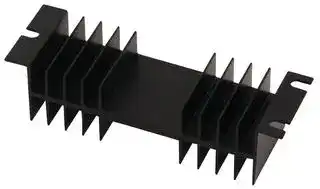
401K
HEAT SINK
⚠️ Reference pricing provided. In case of supply shortages, we will connect you with our trusted procurement partners to ensure your project's continuity.
- Manufacturer: WAKEFIELD THERMAL
- Product type: Natural Convection Heat Sinks
- Thermal Resistance:2.67°C/W; Packages Cooled:TO-3; External Width - Metric:120.7mm; External Height - Metric:31.8mm; External Length - Metric:38.1mm; External Diameter - Metric:-; Heat Sink 58F502
- Thermal Resistance: 2.67°C/W
| Delivery and price | |
|---|---|
| Units per pack | 250 |
| Price | 12.95 € |
| Current stock | 100+ |
| Lead time | 30 days |
Datasheet

**Extruded Heat Sinks**

## _**EXTRUDED HEAT SINKS FOR POWER SEMICONDUCTORS**_

|**621 AND 623 SERIES**|**621 AND 623 SERIES**<br>**_Low-Profile Heat Sinks for All Metal-Case Power Semiconductors_**|**_Low-Profile Heat Sinks for All Metal-Case Power Semiconductors_**|**_Low-Profile Heat Sinks for All Metal-Case Power Semiconductors_**|**_Low-Profile Heat Sinks for All Metal-Case Power Semiconductors_**||_TO-3_|
|---|---|---|---|---|---|---|
||**Footprint**|||**Thermal Performance at Typical Load**|**Thermal Performance at Typical Load**||
|**Standard**|**Dimensions**|**Height**|**Mounting**|**Natural**|**Forced**|**Weight**|
|**P/N**|**in.(mm)**|**in.(mm)**|**Hole Pattern**|**Convection**|**Convection**|**lbs.(grams)**|
|621A|4.750 (120.6) x 1.500 (38.1)|0.461 (11.7)|(1) TO-3|75°C @ 15W|2.0°C/W @ 250 LFM|0.1000 (45.36)|
|621K|4.750 (120.6) x 1.500 (38.1)|0.461 (11.7)|None|75°C @ 15W|2.0°C/W @ 250 LFM|0.1000 (45.36)|
|623A|4.750 (120.6) x 3.000 (76.2)|0.461 (11.7)|(1) TO-3|52°C @ 15W|1.5°C/W @ 250 LFM|0.2100 (95.26)|
|623K|4.750(120.6)x 3.000(76.2)|0.461(11.7)|None|52°C@15W|1.5°C/W@250 LFM|0.210O(95.26)|


A general purpose yet efficient heat dissipator for TO-3 and virtually all other styles of metal case power semiconductor package types, the 621 and 623 Series low-profile flat back heat sinks find a wide variety of applications. The central channel between fins measures 1.300 in. (33.0) (min.)

in width, accommodating many types of packages.  Mounting hole pattern "A" is predrilled for the standard TO-3 package. Material: Aluminum Alloy, Black Anodized.

|**MECHANICAL**<br>**DIMENSIONS**<br>**Dimensions: in. (mm)**<br>0.410<br>(10.4)<br>0.461<br>asmh)<br>a)yd<br>a<br>=<br>¢<br>0.125<br>g<br>(82)<br>|__|<br>1.395<br>—<br>is<br>SS <br>—<br>fet<br>“005s<br>0250|40.0058<br>(1.4)<br>(6.4)<br>(24)<br>TYP4|**MECHANICAL**<br>**DIMENSIONS**<br>**Dimensions: in. (mm)**<br>0.410<br>(10.4)<br>0.461<br>asmh)<br>a)yd<br>a<br>=<br>¢<br>0.125<br>g<br>(82)<br>|__|<br>1.395<br>—<br>is<br>SS <br>—<br>fet<br>“005s<br>0250|40.0058<br>(1.4)<br>(6.4)<br>(24)<br>TYP4|**MECHANICAL**<br>**DIMENSIONS**<br>**Dimensions: in. (mm)**<br>0.410<br>(10.4)<br>0.461<br>asmh)<br>a)yd<br>a<br>=<br>¢<br>0.125<br>g<br>(82)<br>|__|<br>1.395<br>—<br>is<br>SS <br>—<br>fet<br>“005s<br>0250|40.0058<br>(1.4)<br>(6.4)<br>(24)<br>TYP4|**MECHANICAL**<br>**DIMENSIONS**<br>**Dimensions: in. (mm)**<br>0.410<br>(10.4)<br>0.461<br>asmh)<br>a)yd<br>a<br>=<br>¢<br>0.125<br>g<br>(82)<br>|__|<br>1.395<br>—<br>is<br>SS <br>—<br>fet<br>“005s<br>0250|40.0058<br>(1.4)<br>(6.4)<br>(24)<br>TYP4|**621 AND 623 SERIES (EXTRUSION PROFILE 1327)**<br>**NATURAL AND FORCED**<br>**CONVECTION CHARACTERISTICS**<br>**SEMICONDUCTOR MOUNTING HOLES**<br>**A**<br>**K**<br>3.000<br>0.095<br>A<br>(ees TyP4<br>—<br>eoteee<br>i<br>ote0 A<br>settt eet eh at<br>~<br>(111.1)<br>ag OF G2) 1.180<br>#s gi |(7a CPTyl? oe<br>7<br>|02)<br>ssSYpe<br>i 85<br>SS<br>BLANK<br>eu<br>ao DOL<br>i; ee<br> =<br>oseeZ<br>wones<br>[BBSRG<br>———s<br>(108)<br>33%"<br>9<br>/a<br>en<br>ee a<br>fd<br>EO,<br>Pe Fs<br>250||_92s<br>io<br>0220aay<br>tsaree frre “a<br>(635)<br>(64)<br>POWERDISSIPATION(WATTS)|**621 AND 623 SERIES (EXTRUSION PROFILE 1327)**<br>**NATURAL AND FORCED**<br>**CONVECTION CHARACTERISTICS**<br>**SEMICONDUCTOR MOUNTING HOLES**<br>**A**<br>**K**<br>3.000<br>0.095<br>A<br>(ees TyP4<br>—<br>eoteee<br>i<br>ote0 A<br>settt eet eh at<br>~<br>(111.1)<br>ag OF G2) 1.180<br>#s gi |(7a CPTyl? oe<br>7<br>|02)<br>ssSYpe<br>i 85<br>SS<br>BLANK<br>eu<br>ao DOL<br>i; ee<br> =<br>oseeZ<br>wones<br>[BBSRG<br>———s<br>(108)<br>33%"<br>9<br>/a<br>en<br>ee a<br>fd<br>EO,<br>Pe Fs<br>250||_92s<br>io<br>0220aay<br>tsaree frre “a<br>(635)<br>(64)<br>POWERDISSIPATION(WATTS)|**621 AND 623 SERIES (EXTRUSION PROFILE 1327)**<br>**NATURAL AND FORCED**<br>**CONVECTION CHARACTERISTICS**<br>**SEMICONDUCTOR MOUNTING HOLES**<br>**A**<br>**K**<br>3.000<br>0.095<br>A<br>(ees TyP4<br>—<br>eoteee<br>i<br>ote0 A<br>settt eet eh at<br>~<br>(111.1)<br>ag OF G2) 1.180<br>#s gi |(7a CPTyl? oe<br>7<br>|02)<br>ssSYpe<br>i 85<br>SS<br>BLANK<br>eu<br>ao DOL<br>i; ee<br> =<br>oseeZ<br>wones<br>[BBSRG<br>———s<br>(108)<br>33%"<br>9<br>/a<br>en<br>ee a<br>fd<br>EO,<br>Pe Fs<br>250||_92s<br>io<br>0220aay<br>tsaree frre “a<br>(635)<br>(64)<br>POWERDISSIPATION(WATTS)|**621 AND 623 SERIES (EXTRUSION PROFILE 1327)**<br>**NATURAL AND FORCED**<br>**CONVECTION CHARACTERISTICS**<br>**SEMICONDUCTOR MOUNTING HOLES**<br>**A**<br>**K**<br>3.000<br>0.095<br>A<br>(ees TyP4<br>—<br>eoteee<br>i<br>ote0 A<br>settt eet eh at<br>~<br>(111.1)<br>ag OF G2) 1.180<br>#s gi |(7a CPTyl? oe<br>7<br>|02)<br>ssSYpe<br>i 85<br>SS<br>BLANK<br>eu<br>ao DOL<br>i; ee<br> =<br>oseeZ<br>wones<br>[BBSRG<br>———s<br>(108)<br>33%"<br>9<br>/a<br>en<br>ee a<br>fd<br>EO,<br>Pe Fs<br>250||_92s<br>io<br>0220aay<br>tsaree frre “a<br>(635)<br>(64)<br>POWERDISSIPATION(WATTS)|**621 AND 623 SERIES (EXTRUSION PROFILE 1327)**<br>**NATURAL AND FORCED**<br>**CONVECTION CHARACTERISTICS**<br>**SEMICONDUCTOR MOUNTING HOLES**<br>**A**<br>**K**<br>3.000<br>0.095<br>A<br>(ees TyP4<br>—<br>eoteee<br>i<br>ote0 A<br>settt eet eh at<br>~<br>(111.1)<br>ag OF G2) 1.180<br>#s gi |(7a CPTyl? oe<br>7<br>|02)<br>ssSYpe<br>i 85<br>SS<br>BLANK<br>eu<br>ao DOL<br>i; ee<br> =<br>oseeZ<br>wones<br>[BBSRG<br>———s<br>(108)<br>33%"<br>9<br>/a<br>en<br>ee a<br>fd<br>EO,<br>Pe Fs<br>250||_92s<br>io<br>0220aay<br>tsaree frre “a<br>(635)<br>(64)<br>POWERDISSIPATION(WATTS)|
|---|---|---|---|---|---|---|---|---|
||**301/302/303 SERIES**<br>**_Compact Heat Sinks for Dual Stud-Mounted Semiconductor Cases_**|||**_Compact Heat Sinks for Dual Stud-Mounted Semiconductor Cases_**||||_STUD-MOUNT_|
||||**Outline**|**Mounting**||**Thermal Performance at Typical Load**|||
||**Standard**||**Dimensions**|**Length “A”**<br>**Hole (s)**||**Natural**|**Forced**|**Weight**|
||**P/N**||**in. (mm)**|**in. (mm)**<br>**Pattern and Number**||**Convection**|**Convection**|**lbs. (grams)**|
||301K||2.000 (50.8) x 2.000 (50.8)|0.750 (19.1)<br>None||70°C @ 15W|2.5°C/W @ 250 LFM|0.0580 (26.31)|
||301M||2.000 (50.8) x 2.000 (50.8)|0.750 (19.1)<br>(1) 10-32UNF, 0.625 in. thread depth|(1) 10-32UNF, 0.625 in. thread depth|70°C @ 15W|2.5°C/W @ 250 LFM|0.0580 (26.31)|
||301N||2.000 (50.8) x 2.000 (50.8)|0.750 (19.1)<br>(1)1⁄4-28UNF, 0.625 in. thread depth|-28UNF, 0.625 in. thread depth|70°C @ 15W|2.5°C/W @ 250 LFM|0.0580 (26.31)|
||302M||2.000 (50.8) x 2.000 (50.8)|1.500 (38.1)<br>(1) 10-32UNF, 0.625 in. thread depth|(1) 10-32UNF, 0.625 in. thread depth|50°C @ 15W|1.8°C/W @ 250 LFM|0.1330 (60.33)|
||302MM||2.000 (50.8) x 2.000 (50.8)|1.500 (38.1)<br>(2) 10-32UNF, 0.625 in. thread depth|(2) 10-32UNF, 0.625 in. thread depth|50°C @ 15W|1.8°C/W @ 250 LFM|0.1330 (6033)|
||302N||2.000 (50.8) x 2.000 (50.8)|1.500 (38.1)<br>(1)1⁄4-28UNF, 0.625 in. thread depth|-28UNF, 0.625 in. thread depth|5O°C @ 15W|1.8°C/W @ 250 LFM|0.1330 (60.33)|
||302NN|2.000 (50.8) x 2.000 (50.8)<br>A||1.500 (38.1)<br>(2)1⁄4-28UNF, 0.625 in. thread depth|-28UNF, 0.625 in. thread depth|50°C @ 15W|1.8°C/W @ 250 LFM|0.1330 (60.33)|
||303M||2.000 (50.8) x 2.000 (50.8)|3.000 (76.2)<br>(1) 10-32UNF, 0.625 in. thread depth|(1) 10-32UNF, 0.625 in. thread depth|37°C @ 15W|1.3°C/W @ 250 LFM|0.2680 (121.56)|
||303MM||2.000 (50.8) x 2.000 (50.8)|3.000 (76.2)<br>(2) 10-32UNF, 0.625 in. thread depth|(2) 10-32UNF, 0.625 in. thread depth|37°C @ 15W|1.3°C/W @ 250 LFM|0.2680 (121.56)|
||303N<br>A||2.000 (50.8) x 2.000 (50.8)|3.000 (76.2)<br>(1)1⁄4-28UNF, 0.625 in. thread depth|-28UNF, 0.625 in. thread depth|37°C @ 15W|1.3°C/W @ 250 LFM|0.2680 (121.56)|
||303NN||2.000(50.8)x 2.000(50.8)|3.000(76.2)<br>(2)<br>1⁄4-28UNF,0.625 in. thread depth||37°C@15W|1.3°C/W@250 LFM|0.2680(121.56)|
|The large fin area in minimum total volume provided by the radial design of the 301/302/303|The large fin area in minimum total volume provided by the radial design of the 301/302/303<br>302 and 303 Series offer maximum cost savings with dual mounting locations (“MM” and||||302 and 303 Series offer maximum cost savings with dual mounting locations (“MM” and||||
|Series offers maximum heat transfer efficiency in natural convection. All types are available||Series offers maximum heat transfer efficiency in natural convection. All types are available<br>“NN” mounting hole patterns) for two stud-mount devices. Material: Aluminum Alloy, Black|||||||
|with one tapped mounting hole for rectifiers and other stud-mounting semiconductors; the||||with one tapped mounting hole for rectifiers and other stud-mounting semiconductors; the<br>Anodized.|||||


**==> picture [527 x 152] intentionally omitted <==**

**----- Start of picture text -----**<br>
DIMENSIONSMECHANICAL 0.625 NOTE: CROSS-HATCHED AREAS FREE OF ANODIZE. CONVECTION CHARACTERISTICSNATURAL AND FORCED<br>om oD. 2.000 an SEMICONDUCTOR MOUNTING HOLES<br>(19,1) [FREE] OF ANODIZEvooa > aa oso64 | fA[se || anesea F a ee unveoomyee a E<br>0.095i OE: 2 ee625 K oawe M wae N - | 5SEE 4 eerieFA 4033<br>Bea BLANK rn Be aGP<br>302 AND 303 SERIES<br>oars . | 0.05019) SERIES ” . t58)062s saoes || aeey oateget tree38ee<br>301<br>Dimensions: in. (mm) 301 SERIES 302303 Ey 2e00 ees DEPTH DerTH POWER DISSIPATION (WATTS)<br>641 SERIES Maximum Performance Natural Convection Heat Sink for all Metal-Case Semiconductors TO-3<br>Outline Mounting Thermal Performance at Typical Load<br>Standard Dimensions Height Hole Natural Forced Weight<br>P/N in. (mm) in. (mm) Pattern Convection Convection lbs. (grams)<br>641A  A 4.125 (104.8) x 3.000 (76.2) 1.000 (25.4) (1) TO-3 36°C @ 15W 0.9°C/W @ 250 LFM 0.2900 (131.54)<br>ee 641K  4.125 (104.8) x 3.000 (76.2) 1.000 (25.4) None 36°C @ 15W 0.9°C/W @ 250 LFM 0.2900 (131.54)<br>**----- End of picture text -----**<br>


Available with a standard TO-3 mounting hole pattern predrilled for cost-effective mounting in 1.300 in. (33.0) and no predrilled mounting holes can be adapted to meet mounting requirelimited-height applications, the 641 Series provides maximum performance in natural convecments for most metal case power semiconductor types. Material: Aluminum Alloy, Black tion with an optimized heat sink surface area. The 641K type with an open channel area of Anodized.

**==> picture [471 x 79] intentionally omitted <==**

**----- Start of picture text -----**<br>
MECHANICAL 641 SERIES NATURAL AND FORCED<br>DIMENSIONS (25.4)1.000 (EXTRUSION PROFILE 1371) (76.2)3.000 | SEMICONDUCTOR MOUNTING HOLES CONVECTION CHARACTERISTICS AIR VELOCITY (LFM)<br>red 1.335 — (95.3)3.750 0.190 of. A 100 K Sage oeSo<br>(939) 4.125 4g) A I Be BOeel<br>Le | tam ees BLANK ee<br>os pan om ee A, NOWOLES eee<br>“ we tame Bee ace eee<br>(35) (64) (18) 829 ona a2 ee<br>Dimensions: in. (mm) a POWER10 DISSIPATION20 3 (WATTS)0 3<br>**----- End of picture text -----**<br>


All other products, please contact factory for price, delivery, and minimums.

50

Normally stocked

**Extruded Heat Sinks**

|**_EXTRUDED HEAT SINKS FOR POWER SEMICONDUCTORS_**|**_EXTRUDED HEAT SINKS FOR POWER SEMICONDUCTORS_**|
|---|---|
||**401 AND 403 SERIES** **_Double-Surface Heat Sinks for TO-3 Case Styles_**<br>_TO-3; Stud-Mount_|
|Re|**Standard**<br>**Width**<br>**Overall Dimensions**<br>**Height**<br>**Semiconductor**<br>**Thermal Performance at Typical Load**<br>**Weight**<br>**P/N**<br>**in. (mm)**<br>**in. (mm)**<br>**in. (mm)**<br>**Mounting Hole Pattem**<br>**Natural Convection**<br>**Forced Convection**<br>**lbs. (grams)**<br>401A<br>4.750 (120.7)<br>1.500 (38.1)<br>1.250 (31.8)<br>(1) TO-3<br>80°C @ 30W<br>1.5°C/W @ 250 LFM<br>0.1500 (68.04)<br>401F<br>4.750 (120.7)<br>1.500 (38.1)<br>1.250 (31.8)<br>0.270 in. (6.9)-Dia Hole<br>80°C @ 30W<br>1.5°C/W @ 250 LFM<br>0.1500 (68.04)<br>401K<br>4.750 (120.7)<br>1.500 (38.1)<br>1.250 (31.8)<br>None<br>80°C @ 30W<br>1.5°C/W @ 250 LFM<br>0.1500 (68.04)<br>403A<br>4.750 (120.7)<br>3.000 (76.2)<br>1.250 (31.8)<br>(1) TO-3<br>55°C @ 30W<br>0.9°C/W @ 250 LFM<br>0.3500 (158.76)<br>~~AA~~|
||403F<br>4.750 (120.7)<br>3.000 (76.2)<br>1.250 (31.8)<br>0.270 in. (6.9)-Dia Hole<br>55°C @ 30W<br>0.9°C/W @ 250 LFM<br>0.3500 (158.76<br>~~A~~|
||403K<br>4.750(120.7)<br>3.000(76.2)<br>1.250(31.8)<br>None<br>55°C@30W<br>0.9°C/W@250 LFM<br>0.3500(158.76)<br>~~A~~|


With fins oriented vertically in cabinet sidewall applications, 401 and 403 Series heat sinks 0.270 in. (6.9)-diameter mounting hole (with a 0.750 in. (19.1)-diameter area free of anodize) are recommended for critical space applications where maximum heat dissipation is required for mounting stud-type diodes and rectifiers. Hole pattem “V" available upon request. for high-power TO-3 case styles. Forced convection performance is also exemplary with these Material: Aluminum Alloy, Black Anodized. double surface fin types. Semiconductor mounting hole style “F” offers a single centered

|1.250<br>0.095|1.250<br>0.095|1.250<br>0.095|1.250<br>0.095|1.250<br>0.095|1.250<br>0.095||1.500|||
|---|---|---|---|---|---|---|---|---|---|
|**MECHANICAL DIMENSIONS**<br>**SEMICONDUCTOR MOUNTING HOLES**<br>**403 SERIES**<br>**401 SERIES**<br>**Dimensions: in. (mm)**<br>1.250<br>0.095<br>3.000<br>0.055<br>| (31.8)<br>0.095<br>(2.4) R<br>62)<br>(1.4)<br>>}—<br>(24)<br>R—<br>—— 4<br>——<br>4,750<br>——<br>(120.7)<br>3.935<br>rer<br>0.190<br>(29.9)<br>(111.1)<br>(48)<br>———S<br>7335<br>—<br>:<br>—r<br>2500| |,0.250<br>0438<br>(635)<br>(64)<br>(it)|||||||1.500<br>(38.1)<br>{ta}<br>4375<br>(111.1)<br>a<br>of}<br>933<br>4)<br>1.000<br>(25.4)||**NATURAL AND FORCED**<br>**CONVECTION CHARACTERISTICS**<br>AIRVELOCITY(LFM)<br>1992100<br>200 300 400 500 600 700 800 900 1000<br>#o OI RTTALE<br>ee ao INar<br>as<br>eawt|SCg<br>Tt '835<br>an aot NIZA BQ<br>TT ise<br>oo<br>MY Ay<br>36<br>iVALS<br>8<br>Be ot AZbetel<br>08 20<br>reeF/BPS<br>wewT<br>TT TT Tt<br>|) Fe<br>0<br>10 20 9 45 50 60 70 80 90 10<br>©<br>POWER DISSIPATION (WATTS)|
|**A**<br>0.070<br>fooe<br>1)x<br>xs<br>0.430<br>7k<br>SK"<br>Ned<br>{10.8)<br>ot T<br>4.190<br>210<br>e002||**F**<br>0.750<br>0270<br>OI FREEOF<br>£2<br>@ _ANODIZE<br>BOTH SIDES<br>ok<br>J<br>S Ve<br>nN<br>“r||**K**<br>BLANK<br>NO HOLES|**V**<br>0.144og12)<br>iebesa<br>witi29<br>0378 ¥<br>Kr<br>Lox-<br>P. SING<br>A<br>a312,<br>x<br>aK”<br>128 onN's|||**401 AND 403 SERIES**<br>**(EXTRUSION**<br>**PROFILE 1024)**||
||**413/421/423 SERIES**<br>**_Low-Height Double-Surface Heat Sinks for TO-3 Case Styles and Diodes_**<br>_TO-3; DO-5; Stud-Mount_|||||||||
|||**Nominal Dimensions**||||||||
||**Standard**<br>**Width**|||**Length**|**Height “A”**||**Semiconductor**||**Thermal Performance at Typical Load**<br>**Weight**|
||**P/N**|**in. (mm)**||**in. (mm)**|**in. (mm)**||**Mounting Hole Pattern**||**Natural Convection**<br>**Forced Convection**<br>**lbs. (grams)**|
||413A|4.750 (120.7)||3.000 (76.2)|1.875 (47.6)||(1) TO-3||72°C @ 50W<br>0.85°C/W @ 250 LFM<br>0.6300 (285.77)|
||413F|4.750 (120.7)||3.000 (76.2)|1.875 (47.6)||0.270 in. (6.9)-Dia Hole|0.270 in. (6.9)-Dia Hole|72°C @ 50W<br>0.85°C/W @ 250 LFM<br>0.6300 (285.77)|
||413K|413K<br>4.750 (120.7)<br>A||3.000 (76.2)|1.875 (47.6)||None||72°C @ 50W<br>0.85°C/W @ 250 LFM<br>0.6300 (285.77)|
||421A|4.750 (120.7)||3.000 (76.2)|2.625 (66.7)||(1) TO-3||58°C @ 50W<br>0.7°C/W @ 250 LFM<br>0.6300 (285.77)|
||421F|4.750 (120.7)||3.000 (76.2)|2.625 (66.7)||0.270 in. (6.9)-Dia Hole|0.270 in. (6.9)-Dia Hole|58°C @ 50W<br>0.7°C/W @ 250 LFM<br>0.6300 (285.77)|
||421K|421K<br>4.750 (120.7)<br>A||3.000 (76.2)|2.625 (66.7)||None||58°C @ 50W<br>0.7°C/W @ 250 LFM<br>0.6300 (285.77)|
||423A|4.750 (120.7)||5.500 (140.2)|2.625 (66.7)||(1) TO-3||47°C @ 50W<br>0.5°C/W @ 250 LFM<br>1.1700 (530.71)|
||423K<br>~~——~~|423K<br>4.750(120.7)||5.500(140.2)|2.625(66.7)||None||47°C@50W<br>0.5°C/W@250 LFM<br>1.1700(530.71)|


Space-saving double surface 413, 421, and 423 Series utilize finned surface Wakefield Type 126 silicone-free thermal compound or Wakefield DeltaPad™ area on both sides of the power semiconductor mounting surface to provide interface materials for maximum performance. Material: Aluminum Alloy, Black maximum heat dissipation in a compact profile. Ready to install on popular Anodized. power components in natural and forced convection applications. Apply

## **MECHANICAL DIMENSIONS**

**==> picture [504 x 141] intentionally omitted <==**

**----- Start of picture text -----**<br>
NATURAL AND FORCED<br>a 4.750 CONVECTION CHARACTERISTICS<br>4.750 (639) REF 4.375 (ran) 4.375<br>(120.7) “B"<br>135 , | | (111.1) o00 L | (t11.1) AIR VELOCITY (LFM)<br>7 : }-——______]— (4.8) 1.335 ge‘= 'SE109100  TTT200 300 400 500TT Tl800 700 B00 900pe 1000<br>(122)mm (EXTRUSION413 SERIES (33.9) ——femdom oa (EXTRUSION PROFILE 1025)423 SERIES (93.8) i ge boceseesoft<br>PROFILE 2276421 SERIES (eas) 1 64) SEMICONDUCTOR MOUNTING HOLES (122) REF (1279) ey ge352. SeeSCReo SS<br>(EXTRUSION<br>PROFILE 1025) A F 0.750 K ) V a8 Are<br>0.070 oy OS oa cay a<br>DHA (2) 0270 pate or tit baal °  SOWER DISSIPATION WATTS). “<br>SERIES “gr Yeh] |Ee ca gor aT<br>413<br>421 2.625175476) o200“Br” 0.4308 STNy al ae _BOTH1A SIDES NOBLANK HOLES BEYicayl ae<br>(66.7) 0.190 (4.8) ene Ctpr t TIN<br>Dimensions: in. (mm) ay aay ° ep oN<br>**----- End of picture text -----**<br>


All other products, please contact factory for price, delivery, and minimums.

51

Normally stocked

**Extruded Heat Sinks**

## _**EXTRUDED HEAT SINKS FOR POWER SEMICONDUCTORS**_

> **431 AND 433 SERIES** _**High-Performance Heat Sinks for 30-100W Metal Power Semiconductors**_

|**431 AND 433 SERIES**<br>**_High-Performance Heat Sinks for 30-100W Metal Power Semiconductors_**|**_High-Performance Heat Sinks for 30-100W Metal Power Semiconductors_**|**_High-Performance Heat Sinks for 30-100W Metal Power Semiconductors_**|_TO-3; Stud-Mount_|
|---|---|---|---|
|**Nominal Dimensions**||||
|**Standard**<br>**Width**<br>**Length “A”**<br>**Height**|**Semiconductor**|**Thermal Performance at Typical Load**|**Weight**|
|**P/N**<br>**in.(mm)**<br>**in.(mm)**<br>**in.(mm)**<br>**Mounting Hole Pattern**||**Natural Convection**<br>**Forced Convection**|**lbs.(grams)**|
|431K<br>4.750 (120.7)<br>3.000 (76.2)<br>3.000 (76.2)|None|55°C @ 5OW<br>0.40°C/W @ 250 LFM|0.7800 (353.81)|
|433K<br>4.750(120.7)<br>5.500(139.7)<br>3.000(76.2)<br>:|None|42°C@5OW<br>0.28°C/W@250 LFM|1.4900(675.86)|
|Need maximum heat dissipation from a TO-3 rectifier heat sink in|100-watt operating range. Additional interface resistance reduction for maximized overall per-|||
|minimum space? The Wakefield 431 and 433 Series center chan-|formance can be achieved with proper application of Wakefield Type 126 silicone-free thermal|||
|nel double-surface heat sinks offer the highest performance-to-weight ratio for minimum vol-|compound. Material: Aluminum Alloy, Black Anodized.|compound. Material: Aluminum Alloy, Black Anodized.||
|ume occupied for TO-3, diode, and stud-mount metal power semiconductors in the 30- to||||


**MECHANICAL DIMENSIONS** 0.095 **SERIES** wan i” **CONVECTION CHARACTERISTICSNATURAL AND FORCED** . **431** i |io rea =“ ea **433** somo5.500 (139.7) 2) zoms4.500. (508)(114.3) w z= 1902100200 AIR300_400 VELOCITY500 600(LFM)700 800 9001000 = **SEMICONDUCTOR** a s© of TPA ts wie 4750 —L —— agrs **MOUNTING HOLE** ze6 ofmage[AAT TTPyTPPyyee ap 2s 1207) 0,924(82) (339)1.335 (lita) **431 AND 433 K** 22a gopa OA> a tt tT eas ——————_——— **(EXTRUSIONSERIES** <828 NEToASGEE Ets 38 4 p,= **PROFILE 2726)** BLANK eke F/Ree 032) 32 0.375 NO HOLES 4 ptt}t | TT fest; Ey (9.6) “B LL 0.500(12.7) IE 4 Pi0 50 ey100 150i 200tT 250tT 300TT350 400tT 450 500ty v2° **Dimensions: in. (mm)** POWER DISSIPATION (WATTS) **435 SERIES** _**Lightweight Quadruple Mount Heat Sink for TO-3 Case Styles** TO-3_ **Nominal Dimensions Standard Width Length Height Semiconductor Thermal Performance at Typical Load Weight P/N in. (mm) in. (mm) in. (mm) Mounting Hole Pattern Natural Convection Forced Convection lbs. (grams)** 435AAAA 4.250(108.0) 5.500(139.7) 4.300(109.2) (4) TO-3 37°C @ 50W 0.38°C/W @ 250 LFM 1.1500 (521.64) 54°C @ 80W 0.24°C/W @ 600 LFM This lightweight high-performance heat sink is designed to the proper selection and installation of a Wakefield Type 175 DeltaPad Kapton™ interface mount and cool efficiently one to four TO-3 style metal case material for each power semiconductor or, for maximum reduction of case-to-sink interface power semiconductors. The Type 435AAAA is the standard configuration available from stock, loss, the application of Wakefield Type 126 silicone-free thermal compound. Material: predrilled for mounting four TO-3 style devices. Increased performance can be achieved with Aluminum Alloy, Black Anodized.

## **MECHANICAL DIMENSIONS**

> **Dimensions: in. (mm)** MOUNTING SURFACE **NATURAL AND FORCED CONVECTION CHARACTERISTICS** 0,062(1.6) 0500 + DEVIC FOR 5.500 0.095 Rryp4 **SEMICONDUCTOR** - ni0.140 ph 027 490 asp)——————‘LXNT(139.7) (2.4)toy4250 **MOUNTING HOLESAAAA** wocP£6ee oeeermemesa 200300400AIR VELOCITYTTT500SG600 {LFM)700 TF}800 900 1000,elas ge38Fe i] KPC Be ie Be 2.150 Tv (ea) BBAous < one Be SRR oer ms ts 8Ww

> (648) a’ te‘10 a836 oyOoee a = ee03 =< 25 Ld oN $4 10ZA eT 01 FE |. 1.500, 0.750 typ ee **435 SERIES** oo | > z f) z 4.250 5 5,000 | 0.250 **(EXTRUSION** tare «38 =e 0020 30a 50 G0 708080100 (108.0) (38.1) (19.1) (12.7) (6.4) **PROFILE 4226)** rd 13 POWER DISSIPATION (WATTS)

> **441 SERIES** _**High-Performance Natural Convection Heat Sinks for Rectifiers and Diodes** Stud-Mount_ **Nominal Dimensions Standard Width Length Height Semiconductor Thermal Performance at Typical Load Weight P/N in. (mm) in. (mm) in. (mm) Mounting Hole Pattern Natural Convection Forced Convection lbs. (grams)** 441K 4.750 (120.7) 5.500 (139.7) 4.500 (114.3) None 34°C @ SOW 0.30°C/W @ 250 LFM 1.9700 (893.59) 47°C @ 80W 0.19°C/W @ 600 LFM

Designed for vertical mounting within a power supply enclosure convection environment, the 441K Type will achieve thermal resistance of 0.18°C/W (sink to or equipment cabinet without forced airflow available. This ambient) at 1000 LFM. Supplied with no predrilled device mounting hole pattern. Material: Wakefield 441 Series heat sink will dissipate up to 100 watts efficiently in natural convection Aluminum Alloy, Black Anodized. with a maximum 55°C heat sink temperature rise above ambient. When applied in a forced

**==> picture [457 x 59] intentionally omitted <==**

**----- Start of picture text -----**<br>
Dimensions: in. (mm) MECHANICAL DIMENSIONS NATURAL AND FORCED<br>CONVECTION CHARACTERISTICS<br>SEMICONDUCTOR<br>0,093 ti 4 r ‘07 a eas MOUNTING HOLE<br>(24) -k (1143) " (1387) enYe F soo? 100 200 AIR300 VELOCITY400 $00 600 (LFM)700 900 S00<br>J A K 29 of TTT TT<br>fd ; ag a TTT<br>441 SERIES<br>ae 2 i, { Poseeeeseeae<br>(EXTRUSION<br>eya es dey || any PROFILE 1273) au 7 aS<br>**----- End of picture text -----**<br>


All other products, please contact factory for price, delivery, and minimums.

52

Normally stocked

**Extruded Heat Sinks**

## _**EXTRUDED HEAT SINKS FOR POWER SEMICONDUCTORS**_

**==> picture [331 x 10] intentionally omitted <==**

**----- Start of picture text -----**<br>
465 AND 476 SERIES High-Power Heat Sinks for Medium Hex-Type Rectifiers and Diodes<br>**----- End of picture text -----**<br>


|**465 AND 476 SERIES**|**465 AND 476 SERIES**|**_High-Power Heat Sinks for Medium Hex-Type Rectifiers and Diodes_**|**_High-Power Heat Sinks for Medium Hex-Type Rectifiers and Diodes_**|**_High-Power Heat Sinks for Medium Hex-Type Rectifiers and Diodes_**|**_High-Power Heat Sinks for Medium Hex-Type Rectifiers and Diodes_**|**_High-Power Heat Sinks for Medium Hex-Type Rectifiers and Diodes_**||_Stud-Mount_|
|---|---|---|---|---|---|---|---|---|
|||**Nominal Dimensions**|||||||
|**Standard**|**Width**|**Length**|**Height**|**Hex Style**|**Mounting**|**Thermal Performance at Typical Load**||**Weight**|
|**P/N**|**in. (mm)**|**in. (mm)**|**in. (mm)**|**Type**|**Hole Pattern**|**Natural Convection**|**Forced Convection**|**lbs. (grams)**|
|465K|4.000 (101.6)|5.000 (127.0)|4.000 (101.6)|1.060 in. Hex|None|38°C @ 5OW|0.27°C/W @500 LFM|1.9300 (875.45)|
|476K|5.000 (127.0)|6.000 (152.4)|5.000 (127.0)|1.250 in. Hex|None|25°C @ 5OW|0.19°C/W @500 LFM|2.8200(1279.15)|
|476W|5.000 (127.0)|6.000 (152.4)|5.000 (127.0)|1.250 in. Hex|0.765 in.|25°C @ 5OW|0.19°C/W @500 LFM|2.8000(1270.08)|
||||||(19.4)Dia.||||
||||||Center Mount||||
|Wakefield Engineering has designed four standard heat sink types for ease of installation and||||designed for 1.060 in. Hex (465 Type) and 1.250 in. Hex (476 Type). The 476W Type is avail-|designed for 1.060 in. Hex (465 Type) and 1.250 in. Hex (476 Type). The 476W Type is avail-|designed for 1.060 in. Hex (465 Type) and 1.250 in. Hex (476 Type). The 476W Type is avail-||designed for 1.060 in. Hex (465 Type) and 1.250 in. Hex (476 Type). The 476W Type is avail-|
|efficient heat dissipation for industry standard hex-type rectifiers and similar stud-mount||||able predrilled for an 0.765 in. (19.4) dia, mounting hole, Material: Aluminum Alloy, Black||able predrilled for an 0.765 in. (19.4) dia, mounting hole, Material: Aluminum Alloy, Black|||
|power devices: 465, 476, 486, and 489 Series. The 465 and 476 Series shown here are|power devices: 465, 476, 486, and 489 Series. The 465 and 476 Series shown here are|||anodized.|||||


**==> picture [446 x 214] intentionally omitted <==**

**----- Start of picture text -----**<br>
5,000 6.000 MECHANICAL DIMENSIONS ces (101.6) _ ans (127.0)<br>0.093 - (127.0)1.250— 0.195yeaR | +*oa) t HEft @a TIPS<br>a ar ey 4.000 ‘ 2<br>: UE] _ AREA TOBE FREE (101.6) b fg —1'9'. | —_=——_|_<br>(i279) [| :<br>2,000(08) 1.562 1.312 1.250 LL WIT \X 770) |[||,<br>(92.7 23) 8) i 5S<br>a 0500 ad 500 +707<br>L ety r/o<br>0.500(7 .009__| Ci| ee 11.750ee Tery oe 465 SERIES (EXTRUSION  ; ATPS (7.8) NATURAL AND FORCED  (101.8)<br>0.380: (76.2) (45) 5.000 PROFILE 1244) CONVECTION CHARACTERISTICS<br>0.201 DIA 476 SERIES (EXTRUSION<br>Ry en PROFILE 1245) (1279) 0500 AIR VELOCITY (LFM)<br>TYP (127) san 100 200 $06 400 500 600 700 800 s00<br>K W 3a 2dee<3 mtst}otLAof A-—}<br>0.765 er<br>SEMICONDUCTOR (19.4) © DIAANODIZEFREE OF aeaz re)op a(771a fi {|tt[| Jtt| ttt 7<br>MOUNTING HOLES HOLEDIA<br>BLANK 4 “s0THSIDES a36 STa. Se<br>NO HOLES Vat oe LAAAPre<br>¢ ey POA<br>en Af we 2 Ptr rr tt<br>Dimensions: in. (mm) Q 50 100 150 200 250 300 350 400 450<br>**----- End of picture text -----**<br>


## **486 AND 489 SERIES**

## _**Heat Sinks for High-Power Hex-Type Rectifiers and Diodes**_

_Stud-Mount_

||||**Nominal Dimensions**|||||||
|---|---|---|---|---|---|---|---|---|---|
|**Standard**||**Width**|**Length**|**Height**|**Hex Style**|**Mounting**|**Thermal Performance at Typical Load**||**Weight**|
|**P/N**||**in. (mm)**|**in. (mm)**|**in. (mm)**|**Type**|**Hole Pattern**|**Natural Convection**|**Forced Convection**|**lbs. (grams)**|
|486K|486K<br>A|6.250 (158.8)|6.000 (152.4)|6.250 (158.8)|1.750 in. Hex|None|24°C @ 50W|0.20°C/W @250 LFM|4.2100 (1909.66)|
||||||||86°C @ 250W|0.13°C/W @500 LFM||
|489K|489K<br>A|6.250 (158.8)|9.000 (228.6)|6.250 (158.8)|1.750 in. Hex|None|19°C @ 50W|0.15°C/W @250 LFM|6.1400 (2785.10)|
||||||||75°C@250W|0.10°C/W@500 LFM||


These two heat sink types accept industry standard 1.750 in. (44.5) hex-type devices for mounting and efficient heat dissipation. Each type is provided with a 1.750 in. (44.5) x 2.000

in. (50.8) area on the semiconductor base mounting surface which is free of anodize. Material: Aluminum Alloy, Black Anodized.

**==> picture [471 x 189] intentionally omitted <==**

**----- Start of picture text -----**<br>
MECHANICAL DIMENSIONS SEMICONDUCTOR<br>6.250 - MOUNTING HOLE K<br>!<br>0.093 (158.8) 50 a<br>ea) BADATYPS (127) * SHAN<br>OS(2d AREA FREE OF ANODIZE<br>re<br>NATURAL AND FORCED<br>6.250 2.190 4.812 5 CONVECTION CHARACTERISTICS<br>(158.8) (54.1) (46.0) AIR VELOCITY (LFM)<br>| ose _ tan us "00 0TT100 200 300 400 500Ase600 700 800 900<br>4a ca) PS os<br>i Lf am gf tt<br>TT a2 pg [_|t47] Ae<br>Fu SD vATTT<br>L. J TTT<br>(270.500 3.500 0270 0280 Fe e/ayy<br>(689) (69) (4) 486 AND 489 SERIES 2 | ASE ET<br>SERIES age . (EXTRUSION  58 oA Ss<br>‘A 8 PROFILE 1541) Pe tT<br>Dimensions: in. (mm) 486489 6,000 (152.4) 5.000 (127.0) 0 50 100 150 200| 250| 300[eye350 400 450<br>**----- End of picture text -----**<br>


All other products, please contact factory for price, delivery, and minimums.

53

Normally stocked

**Extruded Heat Sinks**

## _**EXTRUDED HEAT SINKS FOR POWER SEMICONDUCTORS**_

**==> picture [452 x 70] intentionally omitted <==**

**----- Start of picture text -----**<br>
|||||||||||
|---|---|---|---|---|---|---|---|---|---|
|490 SERIES|King Size Heat Sinks for High-Power Rectifiers|GENERAL PURPOSE|
|Nominal Dimensions|
|Standard|Width|Length “A”|Height|Semiconductor|Thermal Performance at Typical Load|Weight|
|P/N|in. (mm)|in. (mm)|in. (mm)|Mounting Hole Pattern|Natural Convection|Forced Convection|lbs. (grams)|
|490-35K|9.250 (235.0)|3.500 (88.9)|6.750 (171.5)|None|84°C @ 20OW|0.18°C/W @ 600 LFM|3.2400(1469.66)|
|490-6K|A|9.250 (235.0)|6.000 (152.4)|6.750 (171.5)|None|60°C @ 20OW|0.13°C/W @ 600 LFM|5.4700(2481.19)|
|490-12K|A|9.250 (235.0)|12.000 (304.8)|6.750 (171.5)|None|45°C @ 20OW|0.09°C/W @ 600 LFM|10.62|(4817.23)|

**----- End of picture text -----**<br>


The 490 Series can be used to mount a single high-power rectifier or a grouping of smaller power devices. The semiconductor device mounting surface is free of anodize on the entire surface on one side only; finish overall is black anodize. Use Type 109 mounting brackets (see accessories section) for mounting to enclosure wall and for electrical isolation. The

anodize-free mounting surface is milled for maximum contact area. The 490 Series Can also be drilled for mounting and cooling IGBTs and other isolated power modules. Material: Aluminum Alloy, Black Anodized.

**MECHANICAL DIMENSIONS 490 SERIES (EXTRUSION PROFILE 2131) Dimensions: in. (mm)**

**==> picture [189 x 24] intentionally omitted <==**

**----- Start of picture text -----**<br>
|||
|---|---|
|SEMICONDUCTOR|NATURAL AND FORCED|
|MOUNTING HOLE|CONVECTION CHARACTERISTICS|
|AIR VELOCITY (LFW)|

**----- End of picture text -----**<br>


## _**PERFORMANCE, LOW PROFILE HEAT SINKS FOR POWER MODULES & IGBT’S**_

**394, 395, 396 SERIES**

**==> picture [454 x 79] intentionally omitted <==**

**----- Start of picture text -----**<br>
||||||||||
|---|---|---|---|---|---|---|---|---|
|Thermal Resistance at Typical Load|
|Overall Dimensions: in. (mm)|Device Base|Natural|Forced|
|Standard|Length|Height|Width|Mounting Area|Base Mounting|Convection (Øsa)|[(1)]|Convection (Øsa)|
|P/N|in. (mm)|in. (mm)|in. (mm)|(mm)|Holes|(°C/W)|(°C/W @ 500 LFM)|
|394-1AB|3.000 (76.2)|1.500 (38.1)|5.000 (127.0)|101 x 76|4|1.85|0.90|
|394-2AB|5.500 (139.7)|1.500 (38.1)|5.000 (127.0)|101 x 139|6|1.51|0.60|
|395-1AB|3.000 (76.2)|2.500 (63.5)|5.000 (127.0)|50 x 76|4|1.10|0.50|
|395-2AB|5.500 (139.7)|2.500 (63.5)|5.000 (127.0)|50 x 139|6|0.90|0.32|
|396-1AB|3.000 (76.2)|1.380 (35.1)|5.000 (127.0)|50 x 76|4|1.85|1.07|
|396-2AB|5.500 (139.7)|1.380 (35.1)|5.000 (127.0)|50 x 139|6|1.51|0.64|

**----- End of picture text -----**<br>


_**Note:** 1.Thermal resistance values shown are for black anodized finish at 50°C rise above ambient._

**==> picture [478 x 302] intentionally omitted <==**

**----- Start of picture text -----**<br>
MECHANICAL DIMENSIONS ?— NATURAL AND FORCED<br>o I CONVECTION CHARACTERISTICS<br>(A VELOCITY (LFM)<br>| 3 Dem APT.%<br>a | | | | | ai b= ae —| ott ttm 2<br>394 SERIES i | 3.000 - —- Prid 4s 2 [iato<br>(EXTRUSION PROFILE 7332) fas<br>2500 | rer te 33« ” _IlAas.hetfF jomow<br>1 | | — i = — Bea Sate<br>| Weight _ §* o ECE eee<br>“ a (iz)ia 171ibit ° aNEATDISSIPATED40 60(WATTS) 80 100<br>“ (4 PLA) (6PL-2) NATURAL AND FORCED<br>CONVECTION CHARACTERISTICS<br>AIR VELOCITY (LFM)<br>| |1 5500 PeraAB (50.8) y 100 a »<br>395 SERIES<br>(EXTRUSION PROFILE 7330) 1 3000 ForFaaETaB ge EN i al<br>2.500 | f (76.2) fa| FF Fe#8i23 40 POR-22ab~we SeZ e mana on<br>Sat<br>T ~ | i H a on<br>fara) PEF a 0 Aee<br>(4) a (112.8) 2.55 Ibvft wo # rrr,<br>8 ~fear REF fb asso ° ”HEAT DISSIPATEDsa  (WéeWATTS)<br>0.158ae44 pL.) (@PL2) NATURAL AND FORCED<br>| CONVECTION CHARACTERISTICS<br>2.500T | |I ‘ oO co anvewpory om 00 109,<br>(EXTRUSION PROFILE 7331)396 SERIES | t.S<®ad [octm4 3 71=1 dim0<br>| (76.2)— es nm ea e & HSE© TPee ta<br>2<br>(635)2.500 | | | 3000 196-755 ™ Genfi  FEF 1BEee S40 || || 4 2 2.ert we<br>= 5000 pep ___| 5 20a Se ow<br>0.280 per ryBp °ee<br>[ t a L L Je<br>Dimensions: in. (mm) 8 Garo= )REF its sown HEAT DISSIPATED (WATTS)<br>**----- End of picture text -----**<br>


All other products, please contact factory for price, delivery, and minimums.

54

Normally stocked

**Extruded Heat Sinks**

## _**EXTRUDED HEAT SINKS FOR POWER SEMICONDUCTORS**_

> **SERIES 517, 527, 518 AND 528** _**Heat Sinks for “Half Brick” DC/DC Converters**_

||||||**Thermal Performance**|**Thermal Performance**|
|---|---|---|---|---|---|---|
||**Footprint**||||**Natural Convection**|**Forced Convection**|
|**Standard**|**Dimensions**|**Height**|**Fin**|**Number**|**Power Dissipation (Watts)**|**Thermal Resistance**|
|**P/N**|**in.(mm)**|**in.(mm)**|**Orientation**|**of Fins**|**60°C Rise Heat Sink to Ambient**|**at 300 ft/min**|
|517-95AB|2.28 (57.9) x 2.40 (61.0)|0.95 (24.1)|Horizontal|8|11W|2.0 °C/W|
|527-45AB|2.28 (57.9) x 2.40 (61.0)|0.45 (11.4)|Horizontal|11|7W|3.2 °C/W|
|527-24AB|2.28 (57.9) x 2.40 (61.0)|0.24 (6.1)|Horizontal|11|5W|5.8 °C/W|
|518-95AB|2.40 (61.0) x 2.28 (57.9)|0.95 (24.1)|Vertical|8|11W|2.0 °C/W|
|528-45AB|2.40 (61.0) x 2.28 (57.9)|0.45 (11.4)|Vertical|11|7W|3.2 °C/W|
|528-24AB|2.40(61.0)x 2.28(57.9)|0.24(6.1)|Vertical|11|5W|5.8 °C/W|
|Material: Aluminum, Black Anodized.|||||||


Keep your "half brick" size AT&T and Computer Products power modules cool with these efficient black anodized aluminum heat sinks made for natural or forced convection applications. To include four M3 x 8mm Phillips head SEM attachment screws, add an “M” suffix to stan-

dard part number. To specify factory applied Deltalink IV thermal interface material, add an “S4” suffix to standard part number. Deltalink IV is a non-insulating graphite based material used as a clean, thermally efficient alternative to thermal grease.

**MECHANICAL DIMENSIONS 517, 527, 518 AND 528 SERIES**

**PRODUCT DESIGNATION** PEERED £10 -AB ~~-d~~ WiMiRER H Be i BH a ; H 3 Ii iF || 24 Le i H oaRa GhAninien **Dimensions: in. (mm)**

**==> picture [223 x 6] intentionally omitted <==**

**----- Start of picture text -----**<br>
517/527 SERIES DIMENSIONS 518/528 SERIES DIMENSIONS<br>**----- End of picture text -----**<br>


## _**MOUNTING HARDWARE FOR EXTRUDED HEAT SINKS**_

## 100 SERIES _**PTFE Mounting Insulators**_

|**Standard**|**Description**|**For Use with Series**|**Mounting**||**Hipot Rating**|**Weight**|
|---|---|---|---|---|---|---|
|**P/N**|||**Hardware**|**Material**|**(VAC)**|**lbs. (grams)**|
|L 103|Spool-shaped insulator|300, 400, 600, 111, 113|#6-32 screw|PTFE          1|PTFE          1500|0.00012(0.05)|
|107|Spool-shaped insulator|300, 400, 600, 111, 113|#6-32 screw, nutPTFE|PTFE<br>|5000|0.0034   (1.54)|


## **103 SERIES**

**==> picture [53 x 10] intentionally omitted <==**

**----- Start of picture text -----**<br>
107 SERIES<br>**----- End of picture text -----**<br>


All other products, please contact factory for price, delivery, and minimums.

55

Normally stocked

**Extruded Heat Sinks**

## _**HIGH FIN DENSITY HEAT SINKS FOR POWER MODULES, IGBTs, RELAYS**_

|**Height**<br>**Standard Catalog P/N (5)**<br>**Milled Base(1)**<br>**Nonmilled Base(2)**<br>**Milled**<br>**Nonmilled**<br>**Base Width**<br>**Length**<br>**(“M Series”)**<br>**(“U” Series)**<br>**Base(1)**<br>**Base(2)**<br>**in.(mm)**<br>**in.(mm)**<br>**in.(mm)**<br>**in.(mm)**<br>510-3M<br>510-3U<br>7.380 (187.452)<br>3.000 (76.2)<br>3.106 (78.9)<br>3.136 (79.7)<br>510-6M<br>510-6U<br>7.380 (187.452)<br>6.000 (152.4)<br>3.106 (78.9)<br>3.136 (79.7)<br>510-9M<br>510-9U<br>7.380 (187.452)<br>9.000 (228.6)<br>3.106 (78.9)<br>3.136 (79.7)<br>510-12M<br>510-12U<br>7.380 (187.452)<br>12.000 (304.8)<br>3.106 (78.9)<br>3.136 (79.7)<br>**510, 511 AND 512 SERIES**<br>~~&~~<br>A<br>A|**Height**<br>**Standard Catalog P/N (5)**<br>**Milled Base(1)**<br>**Nonmilled Base(2)**<br>**Milled**<br>**Nonmilled**<br>**Base Width**<br>**Length**<br>**(“M Series”)**<br>**(“U” Series)**<br>**Base(1)**<br>**Base(2)**<br>**in.(mm)**<br>**in.(mm)**<br>**in.(mm)**<br>**in.(mm)**<br>510-3M<br>510-3U<br>7.380 (187.452)<br>3.000 (76.2)<br>3.106 (78.9)<br>3.136 (79.7)<br>510-6M<br>510-6U<br>7.380 (187.452)<br>6.000 (152.4)<br>3.106 (78.9)<br>3.136 (79.7)<br>510-9M<br>510-9U<br>7.380 (187.452)<br>9.000 (228.6)<br>3.106 (78.9)<br>3.136 (79.7)<br>510-12M<br>510-12U<br>7.380 (187.452)<br>12.000 (304.8)<br>3.106 (78.9)<br>3.136 (79.7)<br>**510, 511 AND 512 SERIES**<br>~~&~~<br>A<br>A|**Height**<br>**Standard Catalog P/N (5)**<br>**Milled Base(1)**<br>**Nonmilled Base(2)**<br>**Milled**<br>**Nonmilled**<br>**Base Width**<br>**Length**<br>**(“M Series”)**<br>**(“U” Series)**<br>**Base(1)**<br>**Base(2)**<br>**in.(mm)**<br>**in.(mm)**<br>**in.(mm)**<br>**in.(mm)**<br>510-3M<br>510-3U<br>7.380 (187.452)<br>3.000 (76.2)<br>3.106 (78.9)<br>3.136 (79.7)<br>510-6M<br>510-6U<br>7.380 (187.452)<br>6.000 (152.4)<br>3.106 (78.9)<br>3.136 (79.7)<br>510-9M<br>510-9U<br>7.380 (187.452)<br>9.000 (228.6)<br>3.106 (78.9)<br>3.136 (79.7)<br>510-12M<br>510-12U<br>7.380 (187.452)<br>12.000 (304.8)<br>3.106 (78.9)<br>3.136 (79.7)<br>**510, 511 AND 512 SERIES**<br>~~&~~<br>A<br>A|**Height**<br>**Standard Catalog P/N (5)**<br>**Milled Base(1)**<br>**Nonmilled Base(2)**<br>**Milled**<br>**Nonmilled**<br>**Base Width**<br>**Length**<br>**(“M Series”)**<br>**(“U” Series)**<br>**Base(1)**<br>**Base(2)**<br>**in.(mm)**<br>**in.(mm)**<br>**in.(mm)**<br>**in.(mm)**<br>510-3M<br>510-3U<br>7.380 (187.452)<br>3.000 (76.2)<br>3.106 (78.9)<br>3.136 (79.7)<br>510-6M<br>510-6U<br>7.380 (187.452)<br>6.000 (152.4)<br>3.106 (78.9)<br>3.136 (79.7)<br>510-9M<br>510-9U<br>7.380 (187.452)<br>9.000 (228.6)<br>3.106 (78.9)<br>3.136 (79.7)<br>510-12M<br>510-12U<br>7.380 (187.452)<br>12.000 (304.8)<br>3.106 (78.9)<br>3.136 (79.7)<br>**510, 511 AND 512 SERIES**<br>~~&~~<br>A<br>A|**Height**<br>**Standard Catalog P/N (5)**<br>**Milled Base(1)**<br>**Nonmilled Base(2)**<br>**Milled**<br>**Nonmilled**<br>**Base Width**<br>**Length**<br>**(“M Series”)**<br>**(“U” Series)**<br>**Base(1)**<br>**Base(2)**<br>**in.(mm)**<br>**in.(mm)**<br>**in.(mm)**<br>**in.(mm)**<br>510-3M<br>510-3U<br>7.380 (187.452)<br>3.000 (76.2)<br>3.106 (78.9)<br>3.136 (79.7)<br>510-6M<br>510-6U<br>7.380 (187.452)<br>6.000 (152.4)<br>3.106 (78.9)<br>3.136 (79.7)<br>510-9M<br>510-9U<br>7.380 (187.452)<br>9.000 (228.6)<br>3.106 (78.9)<br>3.136 (79.7)<br>510-12M<br>510-12U<br>7.380 (187.452)<br>12.000 (304.8)<br>3.106 (78.9)<br>3.136 (79.7)<br>**510, 511 AND 512 SERIES**<br>~~&~~<br>A<br>A|**Height**<br>**Standard Catalog P/N (5)**<br>**Milled Base(1)**<br>**Nonmilled Base(2)**<br>**Milled**<br>**Nonmilled**<br>**Base Width**<br>**Length**<br>**(“M Series”)**<br>**(“U” Series)**<br>**Base(1)**<br>**Base(2)**<br>**in.(mm)**<br>**in.(mm)**<br>**in.(mm)**<br>**in.(mm)**<br>510-3M<br>510-3U<br>7.380 (187.452)<br>3.000 (76.2)<br>3.106 (78.9)<br>3.136 (79.7)<br>510-6M<br>510-6U<br>7.380 (187.452)<br>6.000 (152.4)<br>3.106 (78.9)<br>3.136 (79.7)<br>510-9M<br>510-9U<br>7.380 (187.452)<br>9.000 (228.6)<br>3.106 (78.9)<br>3.136 (79.7)<br>510-12M<br>510-12U<br>7.380 (187.452)<br>12.000 (304.8)<br>3.106 (78.9)<br>3.136 (79.7)<br>**510, 511 AND 512 SERIES**<br>~~&~~<br>A<br>A|**Thermal Resistance(5)**<br>**(Øsa) at Typical Load**<br>**Natural**<br>**Forced**<br>**Convection(3)**<br>**Convection(4)**<br>**(°C/W)**<br>**(°C/W @ 100 CFM)**<br>0.56<br>0.088<br>0.38<br>0.070<br>0.29<br>0.066<br>0.24<br>0.062|
|---|---|---|---|---|---|---|
|510-14M|510-14M<br>510-14U<br>7.380 (187.452)<br>14.000 (355.6)<br>A<br>A||3.106 (78.9)||3.136 (79.7)|0.21<br>0.059|
|511-3M|511-3U|5.210 (132.33)<br>3.000 (76.2)|2.350 (59.7)||2.410 (61.2)|0.90<br>0.120|
|511-6M|511-6U|5.210 (132.33)<br>6.000 (152.4)|2,350 (59.7)||2.410 (61.2)|0.65<br>0.068|
|511-9M|511-9U|5.210 (132.33)<br>9.000 (228.6)|2.350 (59.7)||2.410 (61.2)|0.56<br>0.060|
|511-12M|511-12U|5.210 (132.33)<br>12.000 (304.8)|2.350 (59.7)||2.410 (61.2)|0.45<br>0.045|
|512-3M|512-3U|7.200 (182.88)<br>3.000 (76.2)|2.350 (59.7)||2.410 (61.2)|0.90<br>0.120|
|512-6M|512-6U|7.200 (182.88)<br>6.000 (152.4)|2.350 (59.7)||2.410 (61.2)|0.65<br>0.068|
|512-9M|512-9U|7.200 (182.88)<br>9.000 (228.6)|2.350 (59.7)||2.410 (61.2)|0.56<br>0.060|
|512-12M|512-12U|7.200(182.88)<br>12.000(304.8)|2.350(59.7)||2.410(61.2)|0.45<br>0.045|
|**_N o t e s :_**||_2. Nonmilled base flatness: 0.006 in./in._||_4. F o rced convection heat dissipation for distributed heat_|_4. F o rced convection heat dissipation for distributed heat_||
|_1. Precision-milled base for maximum heat transfer_||_3. Natural convection heat dissipation for distributed heat_|_3. Natural convection heat dissipation for distributed heat_||_s o u rces at 100 cubic feet per minute, shrouded condition._||
|_p e rformance (flatness 0.002 in./in.)_||_s o u rces at 50°C rise._||_5. Standard models are provided without finish._|_5. Standard models are provided without finish._||


|**MECHANICAL DIMENSIONS**||
|---|---|
|**Series**<br>**A**<br>**B**<br>**C**<br>**Flatness**<br>511-U  512-U<br>0.250 (6.4)<br>2.410 (61.2)<br>0.372 (9.4)<br>0.006 in./in. (0.15 mm/mm)<br>511-M  512-M 0.220 (5.6)<br>2.350 (59.7<br>0.342 (8.7)<br>0.002 in./in. (0.05 mm/mm)<br>**Dimensions: in. (mm)**<br>**Series**<br>**A**<br>**B**<br>**Flatness**<br>510-U<br>0.216 (5.5)<br>3.136 (79.7)<br>0.006 in./in. (0.15 mm/mm)<br>510-M<br>0.165 (4.2)<br>3.106 (78.9)<br>0.002 in./in. (0.05 mm/mm)<br>**510 SERIES**<br>**510 Series (Extrusion Profile 5113)**<br>**511 Series (Extrusion Profile 6438-1)**<br>**511 AND 512 SERIES**<br>**512 Series (Extrusion Profile 6438-2)**||


**==> picture [95 x 14] intentionally omitted <==**

**----- Start of picture text -----**<br>
NATURAL AND FORCED<br>CONVECTION CHARACTERISTICS<br>**----- End of picture text -----**<br>


## _**392 SERIES HIGH PERFORMANCE HEAT SINKS FOR POWER MODULES, IGBTs AND SOLID STATE RELAYS**_

**==> picture [421 x 251] intentionally omitted <==**

**----- Start of picture text -----**<br>
Thermal Resistance at Typical Load<br>Standard P/N, Finish  Natural Forced<br>Black Gold Length Convection (Øsa) Convection (Øsa) Weight<br>Anodized Iridite in. (mm) (°CW) (°CW) lbs. (grams)<br>3 9 2 - 1 2 0 A B 3 9 2 - 1 2 0 A G 4.725 (120.0) 0 . 5 0 0.16 @ 100 CFM 4.452 (2019.43)<br>392-180AB  a 392-180AG  a 7.087 (180.0) 0 . 4 3 0.11 @ 100 CFM 6.636 (3010.09)<br>a 392-300AB  A 392-300AG  A 11.811 (300.0) 0 . 3 3 0.08 @ 100 CFM 1O.420 (4726.51)<br>NATURAL AND FORCED<br>MECHANICAL DIMENSIONS CONVECTION CHARACTERISTICS<br>4125 (125.0)4.921 AIR FLOW (CFM)<br>(104.8) ~a150 100° 50 100180 200,<br>(80.0) See N AT U R A L neeeerar any aner<br>0.3261 0.150 0.167 C O N V E C T I O N San 4p 4ny4Eere<br>(8.2).326 xx (3.8)0. + tr eo(42) 9= 392-120 (1 MOD)392-180 (1 MOD) Env.VAT400 YT 4Cc>".0R<br>392-300 (1 MOD)<br>0.084 — E eo 392-300 (3 MOD) SATA oe<br>(24) 7, “T! oFwd VIIAAte AATT °*<br>0.116 0.285 x 0.125 <= SEORG00 445.87 e000800<br>(2.9) pia (72)x (3.2) aYr= ett AyoTOTAALiia<br>F O R C E D<br>392 SERIES  C O N V E C T I O N<br>PROFILE 5658)(EXTRUSION  (11 .0)4. 5 28 i)ze PCOttyAIA VT 392-120 (1 MOD)392-120 (3 MOD)392-180 (1 MOD)<br>392-180 (3 MOD)<br>0.328(63) (1358)5.346 B=2a ao LOWHH 392-300 (3 MOD) 02<br>5Fd SOR).UN 48287MLA<br>sen oP TTHAOA SLES TIT<br>0.150150 heDog CLA A RSSORESEoee)<br>88)" FF 0.326 a Of 40882 =e<br>0.208. jie) BZ PBA /G00R000000Seesaee<br>(5.2) (110.0)4.331 oMLIEIT ) 4220ITTeeeIi Ti [Terri)] [96]<br>Dimensions: in. (mm) , i) 100 200 300 400<br>**----- End of picture text -----**<br>


All other products, please contact factory for price, delivery, and minimums.

56

Normally stocked
Updated at April 29, 2026
About Novapart
Novapart is a B2B electronic component broker specialising in stock shortages and cost reduction. We source hard-to-find parts and identify compliant alternatives across a catalogue of 410,000+ components from 500+ manufacturers.
Learn more →Stock Shortage Specialist
When a component is unavailable, discontinued or has an unacceptable lead time, we tap into our network of vetted European and Asian distributors to source what you need — without compromising on quality or traceability.
Request a quote →Compliant Alternatives
We identify pin-to-pin, electrically equivalent substitutes that meet the same certifications (RoHS, AEC-Q100, REACH) as your original specification — validated against datasheets, not just part numbers. Often at a lower cost.
BOM Analysis service →