
Image not available
Illustrative purposes only

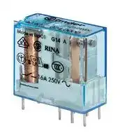
40.61.8.240.4000
Power Relay, Miniature, SPDT, 240 VAC, 16 A, 40 Series, Socket, AC
⚠️ Reference pricing provided. In case of supply shortages, we will connect you with our trusted procurement partners to ensure your project's continuity.
- Manufacturer: FINDER
- Product type: Power Relays
- SVHC: No SVHC (04-Feb-2026)
- Coil Type: AC
- Coil Voltage: 240VAC
- Product Range: 40 Series
- Relay Mounting: Socket
- Coil Resistance: 31.5kohm
- Contact Current: 16A
- Relay Terminals: Plug In
- Contact Material: Silver Tin Oxide
- Contact Voltage VAC: 250V
- Contact Voltage VDC: -
- Contact Configuration: SPDT
| Delivery and price | |
|---|---|
| Units per pack | 50 |
| Price | 9.01 € |
| Current stock | 25+ |
| Lead time | 30 days |
Datasheet

40 SЕRIES

Miniature PCB Relays 8 - 10 - 12 - 16 A

Medical and dentistry Control panels

Panels for electrical distribution Toys

Automation for blinds, grilles and shutters

Door and gate openers Electronic circuit boards Vending machines

Prices, features, specifications, capabilities, appearance and availability of our products and services are subject to change without notice. FINDER assumes no responsibility for the presence of possible errors or insufficient information in this document. In case of discrepancies between the printed and online versions, the latter prevails.

40 SERIES

A

**Power relays 1 and 2 pole for direct  PCB or socket mount**

## **40.31/51**

## **40.52**

## **40.61**

## **Type 40.31/51**

- 1 CO 12 A (3.5 mm pin pitch)

- 1 CO 12 A (5.0 mm pin pitch)

## **Type 40.52**

- 2 CO 8 A (5.0 mm pin pitch)

## **Type 40.61**

- 1 CO 16 A (5.0 mm pin pitch)

- Pin length 3.5 mm for PCB mount

- Pin length 5.3 mm for Plug-in mount

- DC coils (650 mW or 500 mW) and AC coils

- Cadmium-free contact material available

- 1 CO 12 A on PCB, 10 A with socket

- 3.5 mm pin pitch (40.31), 5.0 mm pin pitch (40.51)

- PCB or 95 Series socket mount

- 2 CO 8 A

   - 1 CO 16 A

- 5.0 mm pin pitch

      - 5.0 mm pin pitch

   - PCB or 95 Series socket mount • PCB or 95 Series socket mount

- 8 mm Creepage and Clearance, 6 kV (1.2/50µs) between coil and contact

- Meets EN 60335-1 glow wire requirements

- 95 series sockets for PCB or 35 mm rail mounting (EN 60715) with Screw, Screwless or Push-in terminals

- Coil Indication and EMC suppression modules 99 series and Timer module 86.30 options

- Environmental protection: RT II - flux proof (Standard) RT III - wash tight (Option)

2.5 40.31 6

- Mounted on sockets ≤ 10 A

- **  With the AgSnO2 material the maximum peak current on normally open contact, is 120 A - 5 ms (for 40.61) and 60 A - 5 ms (for 40.52)

40.51

**==> picture [513 x 405] intentionally omitted <==**

**----- Start of picture text -----**<br>
||||||||||
|---|---|---|---|---|---|---|---|---|
|Copper side view|Copper side view|Copper side view|
|F“General technical informationor UL ratings|see:|” page|V|Pin length 3.5 mm for PCB onlyPin length 5.3 mm for PCB or|Pin length 5.3 mm for PCB or sockets|Pin length 3.5 mm for PCB onlyPin length 5.3 mm for PCB or|
|sockets|sockets|
|For outline drawing see page 10|See ordering information|See ordering information|See ordering information|
|Contact specification|
|Contact configuration|1 CO (SPDT)|2 CO (DPDT)|1 CO (SPDT)|
|Rated current/Maximum peak current|A|12*/20|8/15**|16/30**|
|Rated voltage/|
|Maximum switching voltage|V AC|250/400|250/400|250/400|
|Rated load AC1|VA|3000|2000|4000|
|Rated load AC15 (230 V AC)|VA|1000|750|1000|
|Single phase motor rating|(230 V AC)|kW|0.55|0.37|0.55|
|Breaking capacity DC1: 24/110/220 V|A|12/0.6/0.25|8/0.6/0.25|16/0.6/0.25|
|Minimum switching load|mW (V/mA)|300 (5/5)|300 (5/5)|500 (10/5)|
|Standard contact material|AgNi|AgNi|AgCdO|
|Coil specification|
|Nominal voltage (UN)|V AC (50/60 Hz)|6 - 12 - 24 - 48 - 60 - 110 - 120 - 230 - 240|
|V DC|5 - 6 - 7 - 9 - 12 - 14 - 18 - 21 - 24 - 28 - 36 - 48 - 60 - 90 - 110 - 125|
|Rated power AC/DC/sensitive DC|VA (50 Hz)/W/W|1.2/0.65/0.5|1.2/0.65/0.5|1.2/0.65/0.5|
|Operating range|AC|(0.8…1.1)UN|(0.8…1.1)UN|(0.8…1.1)UN|
|DC/sensitive DC|(0.73…1.5)UN/(0.73…1.5)UN|(0.73…1.5)UN/(0.73…1.5)UN|(0.73…1.5)UN/(0.8…1.5)UN|
|Holding voltage|AC/DC|0.8 UN/0.4 UN|0.8 UN/0.4 UN|0.8 UN/0.4 UN|
|Must drop-out voltage|AC/DC|0.2 UN/0.1 UN|0.2 UN/0.1 UN|0.2 UN/0.1 UN|
|Technical data|
|Mechanical life|cycles|10 · 10|[6]|10 · 10|[6]|10 · 10|[6]|
|Electrical life at rated load AC1|cycles|200 · 10|[3]|100 · 10|[3]|100 · 10|[3]|
|Operate/release time|ms|7/3 (10/3 sensitive)|7/3 (12/4 sensitive)|7/3 (10/3 sensitive)|
|Insulation between coil|
|and contacts (1.2/50 µs)|kV|6 (8 mm)|6 (8 mm)|6 (8 mm)|
|Dielectric strength|
|between open contacts|V AC|1000|1000|1000|
|Ambient temperature range|°C|–40…+85|–40…+85|–40…+85|
|Environmental protection|RT II***|RT II***|RT II***|
|Approvals|(according to type)|EAL|@|&|B|RINA|©|Ws®|
|***  See general technical information “Guidelines for automatic flow solder processes” page|II..|

**----- End of picture text -----**<br>


***  See general technical information “Guidelines for automatic flow solder processes” page II..

**3**

40 SERIES

## **Power relays 1 and 2 pole for direct PCB or socket mount**

## **40.62**

## **40.xx.6**

## **Type 40.62**

- A - 2 CO  10A  (5.0 mm pin pitch)

   - DC coils (650 mW or 500 mW) and AC coils

   - Meets EN 60335-1 glow wire requirements

## **Type 40.xx.6**

- Bistable versions of the types 40.31, 40.51, 40.52 and 40.61

- Bistable (single coil)

- Cadmium-free contact material available

- 8 mm Creepage and Clearance, 6 kV (1.2/50µs) between coil and contact

- 95 series sockets for PCB or 35 mm rail mounting (EN 60715) with Screw, Screwless or Push-in terminals

- Environmental protection: RT II - flux proof (Standard) RT III - wash tight (Option)

- 2 CO 10 A

- 5.0 mm pin pitch

- PCB or 95 Series sockets mount

- Bistable (single coil)

- 3.5 or 5.0 mm pin pitch

- PCB or 95 Series socket mount

Bistable version (1 coil) types:

40.31.6… 40.51.6… 40.52.6… 40.61.6…

- With the AgSnO2 material the maximum peak current on normally open contact is 60 A - 5 ms (for 40.62)

|current on normally open contact is<br>60 A - 5 ms (for 40.62)|current on normally open contact is|||||
|---|---|---|---|---|---|
||||Copper side view|For wiring diagrams see  page 10||
|_For ULratings see: _||||||
|_“General technical information” page_V|||Pin length 5.3 mm for|Pin length 5.3 mm for||
||||PCB or sockets|PCB or sockets||
|For outline drawing see page 10||||||
|**Contact specification**<br>Contact configuration|||2 CO (DPDT)|||
|Rated current/Maximumpeak current<br>A|||10/20*|||
|Rated voltage/<br>Maximum switchingvoltage|V AC||250/400|See relays||
|Rated load AC1|VA||2500|40.31||
|Rated load AC15 (230 V AC)|VA||750|40.51||
|Singlephase motor rating(230 V AC)|(230 V AC)<br>kW||0.37|40.52||
|BreakingcapacityDC1: 24/110/220 V<br>A|||10/0.6/0.25|40.61||
|Minimum switchingload|mW (V/mA)||300 (5/5)|page 3||
|Standard contact material<br>**Coil specification**<br>Nominal voltage (UN)|V AC (50/60 Hz)||AgNi<br>110 - 120 - 230 - 240|||
||V DC|5 - 6 - 7 - 9 - 12 - 14 - 18 - 21 - 24 - 28 - 48 - 60 -|5 - 6 - 7 - 9 - 12 - 14 - 18 - 21 - 24 - 28 - 48 - 60 -<br>110 - 125|5 - 6 - 12 - 24 - 48 - 110||
|Ratedpower AC/DC/sens. DC|VA (50 Hz)/W/W||1.2/0.65/0.5|1.0/1.0/—||
|Operating range|AC||(0.8…1.1)UN|(0.8…1.1)UN||
||DC/sens. DC||(0.73…1.5)UN/ (0.73..1.5) UN|(0.8…1.1)UN/ —||
|Holdingvoltage|AC/DC||0.8/0.4 UN||—|
|Must drop-out voltage<br>**Technical data**|AC/DC||0.2/0.1 UN||—|
|Mechanical life|cycles||10 · 106|See relays||
|Electrical life at rated load AC1|cycles||100 · 103|40.31||
|Operate/release time|ms||7/3 (12/4 sensitive)|40.51||
|Insulation between coil||||||
|and contacts(1.2/50µs)|kV||6(8 mm)|40.52||
|Dielectric strength<br>between open contacts<br>Ambient temperature range<br>Environmentalprotection<br>**Approvals**(according to type)|V AC<br>°C|EAL|1000<br>–40…+85<br>RT II<br>@<KrinaAdis|40.61<br>Min. impulse duration<br>≥ 20 ms<br>HI@@KoKsBRINA@Miys||


**  See general technical information “Guidelines for automatic flow solder processes” page II.

**4**

40 SERIES

A

## **Ordering information**

Example:  40 series PCB relay, 2 CO, 230 V AC coil.

**A B C D 4 0 . 5 2 . 8 . 2 3 0 . 0 0 0 0 A: Contact material** See table below

## **D: Special versions**

**Series**

0 =  Standard

**Type**

1 =  Wash tight (RT III)

3 =  PCB/Plug-in - 3.5 mm pinning

**B: Contact circuit**

- 3 =  High temperature (+125 °C) wash tight

5 =  PCB/Plug-in - 5 mm pinning

0 =  CO (nPDT)

6 =  PCB/Plug-in - 5 mm pinning

3 =  NO (nPST)

**No. of poles**

**C: Options**

0 =  Pin length 5.3 mm (Plug-in relays)

1 =  1 pole

- 2 =  Pin length 3.5 mm (PCB relays)

2 =  2 pole

## **Coil version**

6 =  AC/DC bistable

7 =  Sensitive DC, 0.5 W

8 =  AC (50/60 Hz)

9 =  Standard DC, 0.65 W

## **Coil voltage**

See coil specifications

## **Selecting features and options: only combinations in the same row are possible.**

Preferred selections for best availability are shown in **bold.**

|**Terminal pin**|**Type**|**Coil version**|**A**|**B**|**C**|**D**|
|---|---|---|---|---|---|---|
|PCB relay,<br>pin length 3.5 mm|40.31/51|Standard DC/sensitive DC|**1**(AgNi)|**0**- 3|**2**|**0**- 1|
||40.61|Standard DC/sensitive DC|1 (AgNi) -**2**(AgCdO)|**0**- 3|**2**|**0**- 1|
|PCB/Plug-in relay<br>pin length 5.3 mm|40.31/51|AC/sensitive DC|**0**(AgNi) - 2 (AgCdO) - 5 (AgNi+Au)|**0**- 3|**0**|**0**- 1|
||40.31/51|Standard DC|**0**(AgNi) - 2 (AgCdO) - 5 (AgNi+Au)|**0**- 3|**0**|**0**- 1 - 3|
||40.52|AC/sensitive DC|**0**(AgNi) - 4 (AgSnO2) - 5 (AgNi+Au)|**0**- 3|**0**|**0**- 1|
||40.52|Standard DC|**0**(AgNi) - 4 (AgSnO2) - 5 (AgNi+Au)|**0**- 3|**0**|**0**- 1 - 3|
||40.61|AC/sensitive DC|**0**(AgCdO) - 4 (AgSnO2)|**0**- 3|**0**|**0**- 1|
||40.61|Standard DC|**0**(AgCdO) - 4 (AgSnO2)|**0**- 3|**0**|**0**- 1 - 3|
||40.62|AC/DC/sensitive DC|**0**(AgNi) - 4 (AgSnO2)|**0**|**0**|**0**- 1|
||40.31/51/52|Bistable|**0**(AgNi)|**0**|**0**|**0**|
||40.61|Bistable|**0**(AgCdO)|**0**|**0**|**0**|


**5**

40 SERIES

## **Technical data**

**==> picture [540 x 435] intentionally omitted <==**

**----- Start of picture text -----**<br>
Insulation according to EN 61810-1<br>A 1 pole 2 pole<br>Nominal voltage of supply system  V AC 230/400 230/400<br>Rated insulation voltage  V AC 250 400 250 400<br>Pollution degree 3 2 3 2<br>Insulation between coil and contact set<br>Type of insulation Reinforced (8 mm) Reinforced (8 mm)<br>Overvoltage category III III<br>Rated impulse voltage  kV (1.2/50 µs) 6 6<br>Dielectric strength  V AC 4000 4000<br>Insulation between adjacent contacts (40.52)<br>Type of insulation — Basic<br>Overvoltage category — II<br>Rated impulse voltage  kV (1.2/50 µs) — 2.5<br>Dielectric strength  V AC — 2000<br>Insulation between adjacent contacts (40.52 + 40.62)<br>Type of insulation — Basic<br>Overvoltage category — III<br>Rated impulse voltage  kV (1.2/50 µs) — 4<br>Dielectric strength  V AC — 2500<br>Insulation between open contacts<br>Type of disconnection Micro-disconnection Micro-disconnection<br>Dielectric strength  V AC/kV (1.2/50 µs) 1000/1.5 1000/1.5<br>Insulation between coil terminals<br>Rated impulse voltage (surge) differential mode<br>(according to EN 61000-4-5)  kV (1.2/50 µs) 2<br>Other data<br>Bounce time: NO/NC  ms 2/5<br>Vibration resistance (10…150)Hz: NO/NC  g 20/5 (1 changeover) 15/4 (2 changeover)<br>Shock resistance NO/NC  g 20/13 (1 changeover) 20/12 (2 changeover)<br>Power lost to the environment without contact current  W 0.65<br>with rated current  W 1.2 (40.31/51) 2 (40.61/52/62)<br>Recommended distance between relays mounted on PCB  mm ≥ 5<br>**----- End of picture text -----**<br>


**6**

40 SERIES

A

## **Contact specification**

**==> picture [252 x 194] intentionally omitted <==**

**----- Start of picture text -----**<br>
F 40.1 -   Electrical life (AC) v contact current<br>Types 40.31/51/61<br>Resistive load - cosφ = 1<br>Inductive load AC15<br>Cycles Limit for 40.31/51<br>**----- End of picture text -----**<br>


**==> picture [253 x 194] intentionally omitted <==**

**----- Start of picture text -----**<br>
F 40.2 -   Electrical life (AC) v contact current<br>Type 40.52<br>Resistive load - cosφ = 1<br>Inductive load AC15<br>Cycles<br>**----- End of picture text -----**<br>


**F 40.6 -  Electrical life (AC) v contact current** Type 40.62

**==> picture [223 x 121] intentionally omitted <==**

**----- Start of picture text -----**<br>
Resistive load - cosφ = 1<br>Inductive load AC15<br>8 12<br>Cycles<br>**----- End of picture text -----**<br>


**7**

40 SERIES

A

## **Contact specification**

**==> picture [513 x 194] intentionally omitted <==**

**----- Start of picture text -----**<br>
H 40.1 - Maximum DC1 breaking capacity  H 40.6 - Maximum DC1 breaking capacity<br>Types 40.31/51/52/61 Type 40.62<br>40.61 current limit<br>40.31/51 current limit<br>40.52 current limit<br>2 contacts in series<br>40.52 - 2 contacts in series<br>single contact<br>single contact<br>DC voltage (V)<br>DC voltage (V)<br>DC breaking current (A)<br>DC breaking current (A)<br>**----- End of picture text -----**<br>


- When switching a resistive load (DC1) having voltage and current values under the curve, an electrical life of ≥ 100 · 10[3] can be expected.

- In the case of DC13 loads, the connection of a diode in parallel with the load will permit a similar electrical life as for a DC1 load. Note: the release time for the load will be increased.

**8**

40 SERIES

## **Coil specifications**

**==> picture [540 x 68] intentionally omitted <==**

**----- Start of picture text -----**<br>
DC coil data - 0.65 W standard (types 40.31/51/52/61/62) DC coil data - 0.5 W sensitive (types 40.31/51/52/61/62)<br>Nominal  Coil   Operating range Resistance Rated coil  Nominal  Coil   Operating range Resistance Rated coil  A<br>voltage code consumption voltage code consumption<br>UN Umin Umax R I at UN UN Umin* Umax R I at UN<br>V V V Ω mA V V V Ω mA<br>**----- End of picture text -----**<br>


|Nominal<br>voltage<br>UN<br>V|Coil<br>code|Operating range<br>Umin<br>Umax<br>V<br>V|Operating range<br>Umin<br>Umax<br>V<br>V|Resistance<br>R<br>Ω|Rated coil<br>consumption<br>Iat UN<br>mA|Rated coil<br>consumption<br>Iat UN<br>mA|Nominal<br>voltage<br>UN<br>V|Coil<br>code|Operating range<br>Umin*<br>Umax<br>V<br>V|Operating range<br>Umin*<br>Umax<br>V<br>V|Resistance<br>R<br>Ω|Rated coil<br>consumption<br>Iat UN<br>mA|
|---|---|---|---|---|---|---|---|---|---|---|---|---|
|5|**9**.005|3.65|7.5|38|130||5|**7**.005|3.7|7.5|50|100|
|6|**9**.006|4.4|9|55|109||6|**7**.006|4.4|9|75|80|
|7|**9**.007|5.1|10.5|75|94||7|**7**.007|5.1|10.5|100|70|
|9|**9**.009|6.6|13.5|125|72||9|**7**.009|6.6|13.5|160|56|
|12|**9**.012|8.8|18|220|55||12|**7**.012|8.8|18|288|42|
|14|**9**.014|10.2|21|300|47||14|**7**.014|10.2|21|400|35|
|18|**9**.018|13.1|27|500|36||18|**7**.018|13.2|27|650|27.7|
|21|**9**.021|15.3|31.5|700|30||21|**7**.021|15.4|31.5|900|23.4|
|24|**9**.024|17.5|36|900|27||24|**7**.024|17.5|36|1150|21|
|28|**9**.028|20.5|42|1200|23||28|**7**.028|20.5|42|1600|17.5|
|36|**9**.036|26.3|54|2000|18||36|**7**.036|26.3|54|2600|13.8|
|48|**9**.048|35|72|3500|14||48|**7**.048|35|72|4800|10|
|60|**9**.060|43.8|90|5500|11||60|**7**.060|43.8|90|7200|8.4|
|90|**9**.090|65.7|135|12500|7.2||90|**7**.090|65.7|135|16200|5.6|
|110|**9**.110|80.3|165|18000|6.2||110|**7**.110|80.3|165|23500|4.7|
|125|**9**.125|91.2|188|23500|5.3||125|**7**.125|91.2|188|32000|3.9|


*  Umin = 0.8 UN for 40.61

## **AC coil data** (types 40.31/51/52/61/62)

|Nominal<br>voltage<br>UN|Coil<br>code|Operating range<br>Umin<br>Umax|Operating range<br>Umin<br>Umax|Resistance<br>R|Rated coil<br>consumption<br>Iat UN(50 Hz)|
|---|---|---|---|---|---|
|V||V|V|Ω|mA|
|6|**8**.006|4.8|6.6|21|168|
|12|**8**.012|9.6|13.2|80|90|
|24|**8**.024|19.2|26.4|320|45|
|48|**8**.048|38.4|52.8|1350|21|
|60|**8**.060|48|66|2100|16.8|
|110|**8**.110|88|121|6900|9.4|
|120|**8**.120|96|132|9000|8.4|
|230|**8**.230|184|253|28000|5|
|240|**8**.240|192|264|31500|4.1|


|**AC/DC coil data - bistable** (types 40.31/51/52/61)|**AC/DC coil data - bistable** (types 40.31/51/52/61)|**AC/DC coil data - bistable** (types 40.31/51/52/61)|**AC/DC coil data - bistable** (types 40.31/51/52/61)|**AC/DC coil data - bistable** (types 40.31/51/52/61)|**AC/DC coil data - bistable** (types 40.31/51/52/61)|**AC/DC coil data - bistable** (types 40.31/51/52/61)|
|---|---|---|---|---|---|---|
|Nominal<br>voltage<br>UN|Coil<br>code|Operating range <br>Umin<br>Umax||Resistance<br>R|Rated coil<br>consumption<br>Iat UN|DC: Release<br>resistance**<br>RDC|
|V||V|V|Ω|mA|Ω|
|5|**6**.005|4|5.5|23|215|37|
|6|**6**.006|4.8|6.6|33|165|62|
|12|**6**.012|9.6|13.2|130|83|220|
|24|**6**.024|19.2|26.4|520|40|910|
|48|**6**.048|38.4|52.8|2100|21|3600|
|110|**6**.110|88|121|11000|10|16500|


**  RDC = Resistance in DC, RAC = 1.3 x RDC 1 W

**9**

40 SERIES

## **Coil specifications**

A

## **R 40 - DC coil operating range v ambient temperature**

Standard coil

**==> picture [218 x 130] intentionally omitted <==**

## **R 40 - DC coil operating range v ambient temperature**

Sensitive coil, types 40.31/51/52/61/62

**==> picture [190 x 103] intentionally omitted <==**

**----- Start of picture text -----**<br>
40.61<br>40.31/51/52/62<br>**----- End of picture text -----**<br>


## **R 40 - AC coil operating range v ambient temperature**

**==> picture [216 x 118] intentionally omitted <==**

**1 -** Max. permitted coil voltage.

**2 -** Min. pick-up voltage with coil at ambient temperature.

**Wiring diagram for 40 series bistable coil version**

**AC Operation**

## **DC Operation**

**==> picture [197 x 76] intentionally omitted <==**

**==> picture [220 x 73] intentionally omitted <==**

On momentary closure of the SET switch the relay is magnetised through the diode and the relay contacts transfer to the set position and remain in this position.

On momentary closure of the RESET switch the relay is demagnetised through limiting resistor (RAC) and the contacts return to the reset position.

On momentary closure of the SET switch the relay is magnetised and the relay contacts transfer to the set position and remain in this position. On momentary closure of the RESET switch the relay is demagnetised through limiting resistor (RDC) and the contacts return to the reset position.

**Notes:** The minimum SET or RESET impulse time is 20 ms. The maximum time can be continuous. In practice, always ensure that the SET and RESET contacts cannot be operated simultaneously.

## **Outline drawings**

Types 40.31/51/52/61/62

**==> picture [82 x 38] intentionally omitted <==**

* (3.5 or 5.3 mm) see ordering code

**10**

40 SERIES

**==> picture [507 x 591] intentionally omitted <==**

**----- Start of picture text -----**<br>
|||||||||
|---|---|---|---|---|---|---|---|
|a|Module|Socket|a|Relay|Description|Mounting|Accessories|
|99.02|95.P3|40.31|Push-in terminal sockets|Panel or 35 mm rail|- Coil indication and EMC|
|95.P5|40.51|-For fast cable connection|(EN 60715) mount|suppression modules|
|40.52|- Top terminals - Contacts|- Jumper link|
|- Bottom terminals - Coil|- Timer modules|
|95.P5|40.61|
|See page 12|40.62|- Plastic retaining and release|
|clip|
|a.|
|Module|Socket|Relay|Description|Mounting|Accessories|
|ee|ee|ee|PF|
|99.02|95.03|40.31|Screw terminal (Box clamp) socket|Panel or 35 mm rail|- Coil indication and EMC|
|.|[a]|a|
|95.05|40.51|- Top terminals - Contacts|(EN 60715) mount|suppression modules|
|40.52|- Bottom terminals - Coil|- Jumper link|
|- Timer modules|
|ee|95.05|40.61|
|See page 14|40.62|- Plastic retaining and release|
|clip|
|1|
|Module|Socket|Relay|Description|Mounting|Accessories|
|egss|
|99.80|95.83.3|40.31|Screw terminal (Box clamp) socket|Panel or 35 mm rail|- Coil indication and EMC|
|95.85.3|40.51|- Top terminals - NO and COM|(EN 60715) mount|suppression modules|
|40.52|Contacts|- Jumper link|
|40.61|- Bottom terminals - Coil and NC|- Plastic retaining and release|
|40.62|Contacts|clip|
|95.85.3|
|5|Pf|
|See page 15|
|Module|Socket|Relay|Description|Mounting|Accessories|
|ee|ee|ee|Pe|
|99.80|95.93.3|40.31|Screw terminal (Box clamp) socket|Panel or 35 mm rail|- Coil indication and EMC|
|95.95.3|40.51|- Top terminals - Contacts|(EN 60715) mount|suppression modules|
|40.52|- Bottom terminals - Coil|- Jumper link|
|40.61|- Plastic retaining and release|
|40.62|clip|
|AL|95.95.3|a|rf|
|See page 16|
|Module|Socket|Relay|Description|Mounting|Accessories|
|99.01|95.63|40.31|Screw terminal (Box clamp) socket|Panel or 35 mm rail|- Metal retaining clip|
|95.65|40.51|- Top terminals - Contacts|(EN 60715) mount|
|40.52|- Bottom terminals - Coil|
|95.65|40.61|
|See page 17|40.62|
|Module|Socket|Relay|Description|Mounting|Accessories|
|—|95.13.2|40.31|PCB socket|PCB mounting|- Metal retaining clip|
|95.13.2|—|95.15.2|40.51|- Plastic retaining clip|
|See page 18|40.52|
|40.61|
|40.62|

**----- End of picture text -----**<br>


A

**11**

40 SERIES

**==> picture [8 x 10] intentionally omitted <==**

**----- Start of picture text -----**<br>
A<br>**----- End of picture text -----**<br>


|**Push-in terminals socket**panel or 35 mm rail mount<br>For relay type<br>**Accessories**<br>Metal retainingclip|**95.P3**<br>**95.P5**<br>40.31<br>40.51, 40.52, 40.61, 40.62<br>095.71|**95.P3**<br>**95.P5**<br>40.31<br>40.51, 40.52, 40.61, 40.62<br>095.71|
|---|---|---|
|Plastic retaining and release clip<br>(supplied with socket -packagingcode SPA)|095.91.3||
|8-way jumper link|097.58||
|2-way jumper link(12.5 mmpitch)|097.52||
|2-way jumper link(4.6 mmpitch)|097.42||
|Marker tagholder(for tags 060.48 type)|097.00||
|Identification tag|095.00.4||
|Modules(see table below)|99.02||
|Timer modules(see table below)|86.30||
|Sheet of marker tags for plastic retaining and release clip<br>095.91.3 and for marker tag holder 097.00, 48 tags,<br>6 x 12 mm, for CEMBRE thermal transfert printer<br>**Technical data**<br>Rated values|060.48<br>10 A - 250 V*||
|Dielectric strength between coil and contacts(1.2/50μs)|6 kV||
|Protection category|IP 20||
|Ambient temperature<br>°C|–40…+70(see diagram L95)||
|Wire striplength<br>mm|10||
|Min. wire size for 95.P3 and 95.P5 sockets<br>mm2 <br>AWG|solid wire|stranded wire|
||0.5<br>~~Po~~|0.5|
||21<br>~~Po~~|21|
|Max. wire size for 95.P3 and 95.P5 sockets<br>mm2 <br>AWG|solid wire|stranded wire|
||2 x 1.5 / 1 x 2.5|2 x 1.5 / 1 x 2.5|
||2 x 16 / 1 x 14|2 x 16 / 1 x 14|


- For currents > 10 A, contact terminals must be connected in parallel (21 with 11, 24 with 14, 22 with 12). With the relay 40.51 the change-over contact will be 21-12-14.

**L 95 - Total socket current v ambient temperature**

**==> picture [492 x 272] intentionally omitted <==**

**----- Start of picture text -----**<br>
11 COM<br>a i ee 14 NO wo :<br>aasS 12 NC<br>a~ le o le<br>a f et] : :<br>a ; Ae<br>a a A2 A1 COIL P| 3 pied s<br>oe Lt | | | | tt ff] sj<br>2 0 0 20 40 60 80 A con S S —<br>(°C) 30 . 4<br>95.P3 95.P5 71 . 7<br>8-way jumper link  for 95.P3 and 95.P5 sockets 097.58<br>Rated values 10 A - 250 V<br>© 15.8<br>ite<br>2> a p“L LL=) ea LL@2 ABLLBe (=) oO7 2<br>097.58<br>117.2 5.6<br>2-way jumper link  for 95.P3 and 95.P5 sockets 097.52<br>Rated values 10 A - 250 V<br>097.52<br>Total socket current (A)<br>**----- End of picture text -----**<br>


**12**

40 SERIES

**2-way jumper link** for 95.P3 and 95.P5 sockets 097.42 Rated values 10 A - 250 V

A

**097.42**

**==> picture [25 x 7] intentionally omitted <==**

**----- Start of picture text -----**<br>
097.00<br>**----- End of picture text -----**<br>


**86.30** C

**99.02** Approvals (according to type):

DC Modules with non-standard polarity (+A2) on request.

|**Marker tag holder**for 95.P3 and 95.P5 sockets<br>15~~.~~6<br>~~44~~|**Marker tag holder**for 95.P3 and 95.P5 sockets<br>15~~.~~6<br>~~44~~|||097.00<br>||
|---|---|---|---|
|||||||
|||||
|||||
|||||
|||||
|**86 series timer modules**<br>(12…24)V AC/DC;Bi-function: AI,DI; (0.05 s…100 h)<br>(110…125)V AC;Bi-function: AI,DI; (0.05 s…100 h)<br>(230…240)V AC;Bi-function: AI,DI; (0.05 s…100 h)<br>Approvals (according to type):<br>~~C€2S~~ EAL ~~SANs~~|||86.30.0.024.0000<br>86.30.8.120.0000<br>86.30.8.240.0000|
|**99.02 coil indication and EMC suppression modules**||**99.02 coil indication and EMC suppression modules**for 95.P3 and 95.P5 sockets||
|Diode(+A1,standardpolarity)||(6…220)V DC|99.02.3.000.00|
|LED||(6…24)V DC/AC|99.02.0.024.59|
|LED||(28…60)V DC/AC|99.02.0.060.59|
|LED||(110…240)V DC/AC|99.02.0.230.59|
|LED + Diode(+A1,standardpolarity)||(6…24)V DC|99.02.9.024.99|
|LED + Diode(+A1,standardpolarity)||(28…60)V DC|99.02.9.060.99|
|LED + Diode(+A1,standardpolarity)||(110…220)V DC|99.02.9.220.99|
|LED + Varistor||(6…24)V DC/AC|99.02.0.024.98|
|LED + Varistor||(28…60)V DC/AC|99.02.0.060.98|
|LED + Varistor||(110…240)V DC/AC|99.02.0.230.98|
|RC circuit||(6…24)V DC/AC|99.02.0.024.09|
|RC circuit||(28…60)V DC/AC|99.02.0.060.09|
|RC circuit||(110…240)V DC/AC|99.02.0.230.09|
|Residual current by-pass*||(110…240)V AC|99.02.8.230.07|


* Additional 0.9 W power dissipation

**13**

40 SERIES

A

**==> picture [18 x 6] intentionally omitted <==**

**----- Start of picture text -----**<br>
95.05<br>**----- End of picture text -----**<br>


Approvals

(according to type):

Certain relay/socket combinations

**==> picture [23 x 6] intentionally omitted <==**

**----- Start of picture text -----**<br>
095.01<br>**----- End of picture text -----**<br>


**==> picture [22 x 6] intentionally omitted <==**

**----- Start of picture text -----**<br>
060.48<br>**----- End of picture text -----**<br>


|**Screw terminal (Box clamp) socket**panel or 35 mm rail mount<br>For relay type<br>**Accessories**<br>Metal retainingclip|**95.03 (blue)**<br>**95.03.0 (black) 95.05 (blue)**<br>**95.05.0 (black)**<br>40.31<br>40.51, 40.52, 40.61, 40.62<br>095.71|**95.03 (blue)**<br>**95.03.0 (black) 95.05 (blue)**<br>**95.05.0 (black)**<br>40.31<br>40.51, 40.52, 40.61, 40.62<br>095.71|**95.03 (blue)**<br>**95.03.0 (black) 95.05 (blue)**<br>**95.05.0 (black)**<br>40.31<br>40.51, 40.52, 40.61, 40.62<br>095.71|**95.03 (blue)**<br>**95.03.0 (black) 95.05 (blue)**<br>**95.05.0 (black)**<br>40.31<br>40.51, 40.52, 40.61, 40.62<br>095.71|
|---|---|---|---|---|
|Plastic retaining and release clip<br>supplied with socket -packagingcode SPA)|095.01|095.01.0|095.01<br>095.01.0|095.01.0|
|8-way jumper link|095.18|095.18.0|095.18<br>095.18.0|095.18.0|
|Marker tagholder(for tags 060.48 type)|097.00||||
|Identification tag|095.00.4||||
|Modules(see table below)|99.02||||
|Timer modules(see table below)|86.30||||
|Sheet of marker tags for plastic retaining and release clip<br>095.01 and for marker tag holder 097.00, 48 tags, 6 x 12 mm,<br>for CEMBRE thermal transfer printers<br>**Technical data**<br>Rated values|060.48<br>10 A - 250 V*||||
|Dielectric strength between coil and contacts(1.2/50μs)|6 kV||||
|Protection category|IP 20||||
|Ambient temperature<br>°C|–40…+70(see diagram L95)||||
|Screw torque<br>Nm|0.5||||
|Wire striplength<br>mm|8||||
|Max. wire size for 95.03 and 95.05 sockets<br>mm2 <br>AWG <br>~~|~~|solid wire||stranded wire||
||1 x 6 / 2 x 2.5<br>~~|~~||1 x 4 / 2 x 2.5<br>||
||1 x 10 / 2 x 14<br>~~|~~tC“(‘CSC*é*C||1 x 12 / 2 x 14<br>tC“(‘CSC*é*C||


*  For currents > 10 A, contact terminals must be connected in parallel (21 with 11, 24 with 14, 22 with 12). With the relay 40.51 the change-over contact will be 21-12-14.

## **L 95 - Total socket current v ambient temperature**

**==> picture [7 x 68] intentionally omitted <==**

**----- Start of picture text -----**<br>
Total socket current (A)<br>**----- End of picture text -----**<br>


**==> picture [484 x 394] intentionally omitted <==**

**----- Start of picture text -----**<br>
i 11 COM com bio<br>oa a 14 NO . 2<br>PERPEEELLTINS asEEEELEPPrry ST 12 NC AG we | -<br>a ly 8 |> —Jes2 s(cl gs<br>os cianf aeSf ord<br>ope_L} | ptpet I z = | ©<br>2 0 0 20 40 60 80 A2 A1 COIL cot 8 |<br>co) 95.03 ~ 95.05 ~ a 32<br>8-way jumper link  for 95.03 and 95.05 sockets 095.18 (blue) 095.18.0 (black)<br>Rated values 10 A - 250 V<br>095.18<br>aa ot A a a oO<br>SO if —_——________—15 15.8 15.8 110.515.8 15.8 15.8 15 51S<br>86 series timer modules<br>(12…24)V AC/DC; Bi-function: AI, DI; (0.05 s…100 h) 86.30.0.024.0000<br>(110…125)V AC; Bi-function: AI, DI; (0.05 s…100 h) 86.30.8.120.0000<br>(230…240)V AC; Bi-function: AI, DI; (0.05 s…100 h) 86.30.8.240.0000<br>86.30 Ciy™ —— Approvals (according to type):  C E28UK EAL CAN®is<br>99.02 coil indication and EMC suppression modules  for 95.03 and 95.05 sockets<br>Diode (+A1, standard polarity) (6…220)V DC 99.02.3.000.00<br>LED  (6…24)V DC/AC 99.02.0.024.59<br>LED  (28…60)V DC/AC 99.02.0.060.59<br>ot LED  (110…240)V DC/AC 99.02.0.230.59<br>99.02 5: LED + Diode (+A1, standard polarity) (6…24)V DC 99.02.9.024.99<br>Approvals  LED + Diode (+A1, standard polarity) (28…60)V DC 99.02.9.060.99<br>(according to type): LED + Diode (+A1, standard polarity) (110…220)V DC 99.02.9.220.99<br>LED + Varistor  (6…24)V DC/AC 99.02.0.024.98<br>EAL SANs® LED + Varistor  (28…60)V DC/AC 99.02.0.060.98<br>LED + Varistor  (110…240)V DC/AC 99.02.0.230.98<br>DC Modules with   RC circuit  (6…24)V DC/AC 99.02.0.024.09<br>non-standard polarity  RC circuit  (28…60)V DC/AC 99.02.0.060.09<br>(+A2) on request. RC circuit  (110…240)V DC/AC 99.02.0.230.09<br>Residual current by-pass*  (110…240)V AC 99.02.8.230.07<br>P E A<br>P A T E N T<br>RO N<br>U<br>E<br>Total socket current (A)<br>E<br>U<br>NA E POR<br>**----- End of picture text -----**<br>


* Additional 0.9 W power dissipation

**14**

40 SERIES

|**Screw terminal (Box clamp) socket panel**or 35 mm rail mount<br>For relay type<br>**Accessories**<br>Metal retainingclip|or 35 mm rail mount<br>**95.83.3 (blue) 95.83.30 (black) 95.85.3 (blue) 95.85.30 (black)**<br>40.31<br>40.51, 40.52, 40.61, 40.62<br>095.71|or 35 mm rail mount<br>**95.83.3 (blue) 95.83.30 (black) 95.85.3 (blue) 95.85.30 (black)**<br>40.31<br>40.51, 40.52, 40.61, 40.62<br>095.71|or 35 mm rail mount<br>**95.83.3 (blue) 95.83.30 (black) 95.85.3 (blue) 95.85.30 (black)**<br>40.31<br>40.51, 40.52, 40.61, 40.62<br>095.71|or 35 mm rail mount<br>**95.83.3 (blue) 95.83.30 (black) 95.85.3 (blue) 95.85.30 (black)**<br>40.31<br>40.51, 40.52, 40.61, 40.62<br>095.71|
|---|---|---|---|---|
|Plastic retaining and release clip<br>(supplied with socket -packagingcode SPA)|095.91.3|095.91.30<br>095.91.3|095.91.3|095.91.30|
|8-way jumper link|095.08|095.08.0<br>095.08|095.08|095.08.0|
|Identification tag|095.00.4||||
|Modules(see table below)|99.80||||
|Marker tagholder|097.00||||
|Sheet of marker tags for plastic retaining and release clip<br>095.91.3, 48 tags, 6 x 12 mm, for CEMBRE thermal transfert<br>printer<br>**Technical data**<br>Rated values|mm, for CEMBRE thermal transfert<br>060.48<br>10 A - 250 V*||||
|Dielectric strength between coil and contacts(1.2/50μs)|6 kV<br>2 kV||2 kV||
|Protection category|IP 20||||
|Ambient temperature|°C –40…+70(see diagram L95)||||
|Screw torque<br>Nm|Nm 0.5||||
|Wire striplength<br>mm|mm 7<br>~~|~~||||
|Max. wire size for 95.83.3 and 95.85.3 sockets<br>mm<br>AWG|solid wire<br>stranded wire<br>mm2 1 x 6 / 2 x 2.5<br>1 x 4 / 2 x 2.5<br>~~|~~t—“‘CSC;*‘*C||stranded wire||
||||1 x 4 / 2 x 2.5||
||AWG 1 x 10 / 2 x 14<br>1 x 12 / 2 x 14||1 x 12 / 2 x 14||


*  For currents > 10 A, contact terminals must be connected in parallel (21 with 11, 24 with 14, 22 with 12). With the relay 40.51 the change-over contact will be 21-12-14.

## **L 95 - Total socket current v ambient temperature**

95.83.3 95.85.3 095.08 (blue) 095.08.0 (black) 10 A - 250 V

**==> picture [374 x 88] intentionally omitted <==**

**----- Start of picture text -----**<br>
8-way jumper link  for 95.83.3 and 95.85.3 sockets<br>Rated values<br>« EZ o 113.1 13.9<br>~—f?tt?dtdétet?edéei(Ee ES ES ES ES SS Ee fw ret#o<br>095.08<br>0 . 75 1 58 1 58 1 58 1 58 1 58 1 58 15 . 8<br>fs 99.80 coil indication and EMC suppression modules  for 95.83.3 and 95.85.3 sockets<br>P E A<br>P A T E N T<br>RO N<br>U<br>E E<br>U<br>NA E POR<br>**----- End of picture text -----**<br>


||**Blue***|
|---|---|
|Diode(+A1,standardpolarity)<br>(6…220)|)V DC 99.80.3.000.00|
|LED<br>(6…24)V DC/AC|V DC/AC 99.80.0.024.59|
|LED<br>(28…60)V DC/AC|V DC/AC 99.80.0.060.59|
|LED<br>(110…240)V DC/AC|V DC/AC 99.80.0.230.59|
|LED + Diode(+A1,standardpolarity)<br>(6…24)|)V DC 99.80.9.024.99|
|LED + Diode(+A1,standardpolarity)<br>(28…60)|)V DC 99.80.9.060.99|
|LED + Diode(+A1,standardpolarity)<br>(110…220)|)V DC 99.80.9.220.99|
|LED + Varistor<br>(6…24)V DC/AC|V DC/AC 99.80.0.024.98|
|LED + Varistor<br>(28…60)V DC/AC|V DC/AC 99.80.0.060.98|
|LED + Varistor<br>(110…240)V DC/AC|V DC/AC 99.80.0.230.98|
|RC circuit<br>(6…24)V DC/AC|V DC/AC 99.80.0.024.09|
|RC circuit<br>(28…60)V DC/AC|V DC/AC 99.80.0.060.09|
|RC circuit<br>(110…240)V DC/AC|V DC/AC 99.80.0.230.09|
|Residual current by-pass*<br>(110…240)|)V AC 99.80.8.230.07|


## **99.80**

Approvals (according to type):

*  Modules in Black housing are available on request.

Green LED is standard. Red LED available on request.

* Additional 0.9 W power dissipation

**15**

40 SERIES

A

**==> picture [65 x 29] intentionally omitted <==**

**----- Start of picture text -----**<br>
95.95.3<br>Approvals<br>(according to type):<br>**----- End of picture text -----**<br>


**==> picture [28 x 5] intentionally omitted <==**

**----- Start of picture text -----**<br>
095.91.3<br>**----- End of picture text -----**<br>


**060.48** —

|**Screw (Box clamp) terminal socket**panel or 35 mm rail mount<br>For relay type<br>**Accessories**<br>Metal retainingclip|panel or 35 mm rail mount<br>**95.93.3 (blue)**<br>**95.93.30 (black)**<br>**95.95.3 (blue)**<br>**95.95.30 (black)**<br>40.31<br>40.51, 40.52, 40.61, 40.62<br>095.71|panel or 35 mm rail mount<br>**95.93.3 (blue)**<br>**95.93.30 (black)**<br>**95.95.3 (blue)**<br>**95.95.30 (black)**<br>40.31<br>40.51, 40.52, 40.61, 40.62<br>095.71|panel or 35 mm rail mount<br>**95.93.3 (blue)**<br>**95.93.30 (black)**<br>**95.95.3 (blue)**<br>**95.95.30 (black)**<br>40.31<br>40.51, 40.52, 40.61, 40.62<br>095.71|panel or 35 mm rail mount<br>**95.93.3 (blue)**<br>**95.93.30 (black)**<br>**95.95.3 (blue)**<br>**95.95.30 (black)**<br>40.31<br>40.51, 40.52, 40.61, 40.62<br>095.71|
|---|---|---|---|---|
|Plastic retaining and release clip<br>(supplied with socket -packagingcode SPA)|095.91.3|095.91.30|095.91.3|095.91.30|
|8-way jumper link|095.08|095.08.0|095.08|095.08.0|
|Identification tag|095.00.4||||
|Modules(see table below)|99.80||||
|Sheet of marker tags for plastic retaining and release clip<br>095.91.3 and for marker tag holder 097.00, 48 tags,<br>6 x 12 mm, for CEMBRE thermal transfer printers<br>**Technical data**<br>Rated values|060.48<br>10 A - 250 V*||||
|Dielectric strength between coil and contacts(1.2/50μs)|6 kV||||
|Protection category|IP 20||||
|Ambient temperature<br>°C|°C –40…+70(see diagram L95)||||
|Screw torque<br>Nm|Nm 0.5||||
|Wire striplength<br>mm|mm 8||||
|Max. wire size for 95.93.3 and 95.95.3 sockets<br>mm<br>AWG|solid wire<br>mm2 1 x 6 / 2 x 2.5<br>~~|~~||stranded wire||
||||1 x 4 / 2 x 2.5||
||AWG 1 x 10 / 2 x 14<br>~~|~~||1 x 12 / 2 x 14||


*  For currents > 10 A, contact terminals must be connected in parallel (21 with 11, 24 with 14, 22 with 12). With the relay 40.51 the change-over contact will be 21-12-14.

## **L 95 - Total socket current v ambient temperature**

**==> picture [78 x 56] intentionally omitted <==**

**----- Start of picture text -----**<br>
ZF<br>095.08<br>P E A<br>P A T E N T<br>RO N<br>U<br>E E<br>U<br>NA E POR<br>**----- End of picture text -----**<br>


95.93.3 95.95.3 **8-way jumper link** for 95.93.3 and 95.95.3 sockets 095.08 (blue) 095.08.0 (black) Rated values 10 A - 250 V rey ~~113.1 13.9~~

## **99.80 coil indication and EMC suppression modules** for 95.93.3 and 95.95.3 sockets

**==> picture [18 x 6] intentionally omitted <==**

**----- Start of picture text -----**<br>
99.80<br>**----- End of picture text -----**<br>


Approvals

(according to type):

- Modules in Black housing are available on request.

Green LED is standard. Red LED available on request.

||**Blue***|
|---|---|
|Diode(+A1,standardpolarity)<br>(6…220)V DC|V DC 99.80.3.000.00|
|LED<br>(6…24)V DC/AC|V DC/AC 99.80.0.024.59|
|LED<br>(28…60)V DC/AC|V DC/AC 99.80.0.060.59|
|LED<br>(110…240)V DC/AC|V DC/AC 99.80.0.230.59|
|LED + Diode(+A1,standardpolarity)<br>(6…24)V DC|V DC 99.80.9.024.99|
|LED + Diode(+A1,standardpolarity)<br>(28…60)V DC|V DC 99.80.9.060.99|
|LED + Diode(+A1,standardpolarity)<br>(110…220)V DC|V DC 99.80.9.220.99|
|LED + Varistor<br>(6…24)V DC/AC|V DC/AC 99.80.0.024.98|
|LED + Varistor<br>(28…60)V DC/AC|V DC/AC 99.80.0.060.98|
|LED + Varistor<br>(110…240)V DC/AC|V DC/AC 99.80.0.230.98|
|RC circuit<br>(6…24)V DC/AC|V DC/AC 99.80.0.024.09|
|RC circuit<br>(28…60)V DC/AC|V DC/AC 99.80.0.060.09|
|RC circuit<br>(110…240)V DC/AC|V DC/AC 99.80.0.230.09|
|Residual current by-pass*<br>(110…240)V AC|V AC 99.80.8.230.07|


* Additional 0.9 W power dissipation

**16**

40 SERIES

|**Screw terminal (Box clamp) socket**panel or 35 mm rail mount<br>For relay type<br>**Accessories**<br>Metal retainingclip|**95.63**<br>**95.65**<br>40.31<br>40.51, 40.52, 40.61, 40.62<br>095.71|**95.63**<br>**95.65**<br>40.31<br>40.51, 40.52, 40.61, 40.62<br>095.71|
|---|---|---|
|8-way jumper link|095.08|095.08|
|Modules (see table below)<br>**Technical data**<br>Rated values|99.01<br>—<br>10 A - 250 V*<br>~~oo~~||
|Dielectric strength between coil and contacts(1.2/50μs)|6 kV<br>~~oo~~|2 kV|
|Protection category|IP 20||
|Ambient temperature<br>°C <br>Screw torque<br>Nm|–40…+70(see diagram L95)<br>0.5||
|Screw torque<br>Nm <br>Wire striplength<br>mm|0.5<br> 7||
|Max. wire size for 95.63 and 95.65 sockets<br>mm2 <br>AWG|solid wire|stranded wire|
||1 x 6 / 2 x 2.5|1 x 4 / 2 x 2.5|
||1 x 10 / 2 x 14|1 x 12 / 2 x 14|


**==> picture [69 x 29] intentionally omitted <==**

**----- Start of picture text -----**<br>
95.63<br>Approvals<br>(according to type):<br>**----- End of picture text -----**<br>


**95.65** Approvals *  For currents > 10 A, contact terminals must be connected in parallel (21 with 11, 24 with 14, 22 with 12). (according to type): With the relay 40.51 the change-over contact will be 21-12-14.

## **L 95 - Total socket current v ambient temperature**

**==> picture [160 x 7] intentionally omitted <==**

**----- Start of picture text -----**<br>
95.63 95 . 65 95.65<br>**----- End of picture text -----**<br>


**==> picture [392 x 58] intentionally omitted <==**

**----- Start of picture text -----**<br>
8-way jumper link  for 95.63 and 95.65 sockets 095.08 (blue)<br>Rated values 10 A - 250 V<br>ZF roo) 113.1 13.9<br>095.08 ~PrrrSS => >=rr=> — = ——ttas r eOo<br>P E A<br>P A T E N T<br>RO N<br>U<br>E E<br>U<br>NA E POR<br>**----- End of picture text -----**<br>


095.08 (blue)

## **99.01 coil indication and EMC suppression modules** for type 95.63 socket

||**Blue***|
|---|---|
|Diode (+A1, standardpolarity)<br>(6…220)V DC|99.01.3.000.00|
|Diode (+A2, non-standardpolarity)<br>(6…220)V DC|99.01.2.000.00|
|LED<br>(6…24)V DC/AC|99.01.0.024.59|
|LED<br>(28…60)V DC/AC|99.01.0.060.59|
|LED<br>(110…240)V DC/AC|99.01.0.230.59|
|LED + Diode (+A1, standardpolarity)<br>(6…24)V DC|99.01.9.024.99|
|LED + Diode (+A1, standardpolarity)<br>(28…60)V DC|99.01.9.060.99|
|LED + Diode (+A1, standardpolarity)<br>(110…220)V DC|99.01.9.220.99|
|LED + Diode (+A2, non-standardpolarity)<br>(6…24)V DC|99.01.9.024.79|
|LED + Diode (+A2, non-standardpolarity)<br>(28…60)V DC|99.01.9.060.79|
|LED + Diode (+A2, non-standardpolarity)<br>(110…220)V DC|99.01.9.220.79|
|LED + Varistor<br>(6…24)V DC/AC|99.01.0.024.98|
|LED + Varistor<br>(28…60)V DC/AC|99.01.0.060.98|
|LED + Varistor<br>(110…240)V DC/AC|99.01.0.230.98|
|RC circuit<br>(6…24)V DC/AC|99.01.0.024.09|
|RC circuit<br>(28…60)V DC/AC|99.01.0.060.09|
|RC circuit<br>(110…240)V DC/AC|99.01.0.230.09|
|Residual current by-pass*<br>(110…240)V AC|99.01.8.230.07|


* Additional 0.9 W power dissipation

**17**

40 SERIES

A

|**PCB socket**<br>For relay type<br>**Accessories**<br>Metal retaining clip (supplied with socket -<br>packagingcode SMA)|**95.13.2 (blue) 95.13.20 (black) 95.15.2 (blue) 95.15.20 (black)**<br>40.31<br>40.51, 40.52, 40.61, 40.62<br>095.51<br>——|
|---|---|
|Plastic retaining clip<br>**Technical data**<br>Rated values|095.52<br>12 A - 250 V<br>10 A - 250 V*|
|Dielectric strength between coil and contacts(1.2/50μs)|6 kV|
|Protection category|IP 20|
|Ambient temperature<br>°C|–40…+70|


**==> picture [341 x 160] intentionally omitted <==**

**----- Start of picture text -----**<br>
40.31 Ye 7 8, 40.51 Ss a 25<br>13 12 14 22 24 13<br>7.5 A1 12 11 14<br>11 21<br>tt A2 22 21 24 A1 re A2 Ny :<br>[F 40.52 ae e<br>fe )<br>95.13.2 95.15.2<br>Copper side view Copper side view<br>A 121114 wl<br>A2 22 2124 athe<br>40.61<br>3.5<br>30 20 3.5<br>1.5<br>**----- End of picture text -----**<br>


## **Packaging codes**

**How to code and identify retaining clip and packaging options for sockets.**

Example:

**9 5 . P 5 S P A A** Standard packaging **SM** Metal retaining clip **SP** Plastic retaining clip

Please see general technical information

**18**
Updated at June 7, 2026
About Novapart
Novapart is a B2B electronic component broker specialising in stock shortages and cost reduction. We source hard-to-find parts and identify compliant alternatives across a catalogue of 410,000+ components from 500+ manufacturers.
Learn more →Stock Shortage Specialist
When a component is unavailable, discontinued or has an unacceptable lead time, we tap into our network of vetted European and Asian distributors to source what you need — without compromising on quality or traceability.
Request a quote →Compliant Alternatives
We identify pin-to-pin, electrically equivalent substitutes that meet the same certifications (RoHS, AEC-Q100, REACH) as your original specification — validated against datasheets, not just part numbers. Often at a lower cost.
BOM Analysis service →